1
The
H
F-Transceiver
HF-Transceiver
Kenwood TS-830
Survival Guide
PART I
edited by
Olaf Rettkowski DL9AI
2
VERSION
Kenwood TS-830 Survival Guide, ed. Olaf Rettkowski, DL9AI, ver.1.2, 03 Dec 2002
REFERENCE
This is a collection of material found on the net. For reference and further information visit
the following sites and/or see the following papers:
http://myweb.tiscali.co.uk/martin.atwsm/TS830S.html , Martin, G1XGX
http://www.vcnet.com/measures/830.html , Richard L. Measures, AG6K
http://www.eham.net
http://www.mods.dk
http://groups.yahoo.com/group/Amateur-repairs
http://www.kenwood.net
Kenwood TS-830S Operating Manual
Kenwood TS-830S Service Manual
3
1
Preface .........................................................................................................................6
2
Read first ! ...................................................................................................................6
3
History of this document ............................................................................................7
4
To-Do list .....................................................................................................................7
5
General Description....................................................................................................7
6
Problems and known Fixes ........................................................................................8
6.1
6.21
6.22
Excessive delay in relay control signal to external amplifier--which causes hot
switching in the amplifier's RF relays ..........................................................................8
Frequency drift..............................................................................................................8
Frequency drift during warm-up...................................................................................9
TS-830S Frequency Drift - "FIX" switch .....................................................................9
Frequency jumping .......................................................................................................9
Intermittent shift in display and operating frequency.................................................10
Intermittent ALC on transmit .....................................................................................11
Problem 1: Intermittent ALC indication [TX] on only one band ...............................11
Problem 2: Intermittent ALC on transmit...................................................................11
Lack of crispness in receive audio..............................................................................11
Lack of crispness in transmit audio ............................................................................12
No power output on most bands .................................................................................12
Noisy or intermittent front panel control potentiometers [pots] .................................12
On the AF-AVR Unit, the 4-pole relay contacts which switch the bias to the finals
may fail after extensive use. .......................................................................................12
Peak-distortion in the RX audio .................................................................................13
Poor, transmit, SSB carrier-suppression after alignment............................................13
Power-output falls off when the key is held down .....................................................13
Premature 12V pilot lamp burnout .............................................................................13
Rapid jumps in VFO frequency..................................................................................14
Receive [RX] signals intermittently drop roughly 40 db............................................14
Receiver AGC-overshoot, causing receive audio-distortion on voice-peaks and
concurrent S-meter overshoot.....................................................................................14
Television interference with the radio transmitting into a 50 Ohm, shielded
termination..................................................................................................................14
Receive suffers or goes out after QRO modification..................................................15
Transmitter "talkback"................................................................................................15
7
Problems and Hints from Newsgroups ...................................................................16
7.1
7.2
7.3
7.4
7.5
7.5.1
Beware of high voltage!!!...........................................................................................16
No sidetone when keying CW, VOX doesn't work on CW........................................16
Resistor replacement after grid-to-cathode short of the 6146 tubes ...........................16
Difference between 6146B und 6146W tubes ............................................................16
Slow power drop-off...................................................................................................17
Slow power drop-off: Answer 1 .................................................................................17
6.2
6.3
6.4
6.5
6.6
6.7
6.7.1
6.7.2
6.8
6.9
6.10
6.11
6.12
6.13
6.14
6.15
6.16
6.17
6.18
6.19
6.20
4
7.5.2
7.5.3
7.5.4
7.6
7.6.1
7.6.2
7.6.3
7.7
7.8
7.9
7.10
7.11
7.12
7.13
7.14
7.15
7.16
7.17
7.18
7.19
7.20
7.21
7.22
7.23
7.24
7.25
Slow power drop-off: Answer 2 .................................................................................17
Slow power drop-off: Answer 3 .................................................................................17
Slow power drop-off: Answer 4 .................................................................................18
Low power output.......................................................................................................18
Low power output: Answer 1 .....................................................................................18
Low power output: Answer 2 .....................................................................................18
Low power output: Answer 3 .....................................................................................18
Intermittend drop of power output .............................................................................19
Problem peaking Drive control ..................................................................................19
Intermittent loss of drive to final ................................................................................19
No dip on the plate current and no or small output ....................................................20
Reducing power output to QRP-like levels, No.1 ......................................................20
Reducing power output to QRP-like levels, No.2 ......................................................20
Increasing power output / QRO-modification, No.1 ..................................................21
Increasing power output / QRO-modification, No.2 ..................................................21
Intermittent loss of audio............................................................................................22
Final tubes replacement and neutralization ................................................................22
Low power output on 160 m only ..............................................................................22
Crystals for FIX band selection ..................................................................................23
Changed DRIVE setting after final tubes replacement is normal ..............................23
Difference between TS-830 and TS-830 "gold label"................................................23
Microphone impedance matching ..............................................................................23
Problem with TS-830 TX relay ..................................................................................24
No operation on WARC bands...................................................................................24
Receiver signal attenuation when keying the microphone or rocking the bandswitch
....................................................................................................................................25
VOX trip problem.......................................................................................................25
8
Maintenance Procedures..........................................................................................25
8.1
8.2
8.3
8.4
VFO Lubrication ........................................................................................................25
Fan Lubrication ..........................................................................................................26
VBT [Variable {selectivity} Bandwidth Tuning] Oscillator Alignment [approx.
8375 KHz] ..................................................................................................................26
USB/LSB Carrier Oscillator Alignment.....................................................................27
9
Modifications.............................................................................................................27
9.1
9.2
9.3
9.4
9.5
9.6
9.7
9.8
AMTOR modification ................................................................................................27
WARC modification...................................................................................................28
RIT / XIT modifications .............................................................................................28
VFO-230 fine tune mod..............................................................................................28
TS-830S Low Voltage Supply Optional Improvements ............................................28
Kenwood TS-830 filter modification .........................................................................29
TS-830S Operation on 240 V AC ..............................................................................30
TS-830S Noise Blanker Optional Improvements.......................................................30
10
Product Reviews .......................................................................................................31
5
10.1
10.1.1
10.1.2
10.1.3
10.1.4
10.1.5
10.1.6
10.1.7
10.1.8
10.1.9
10.1.10
10.1.11
10.1.12
10.1.13
10.1.14
10.1.15
10.1.16
10.1.17
10.1.18
Opinions and Ratings of TS-830 owners....................................................................31
Great Radio, Rating: 5 of 5.........................................................................................31
I miss mine, Rating: 5 of 5..........................................................................................32
Good but aging, Rating: 5 of 5 ...................................................................................32
TS-830 The Best of the Best, Rating: 5 of 5...............................................................32
Brilliant audio from 830, Rating: 5 of 5 .....................................................................32
Excellent Radio on the used Market, Rating: 5 of 5...................................................32
Excellent Radio, Rating: 5 of 5...................................................................................32
A quality classic, Rating: 5 of 5..................................................................................33
Still Impressive after all these years, Rating: 5 of 5 ...................................................33
One of the very best, Rating: 5 of 5............................................................................33
Will never say 'goodbye', Rating: 5 of 5.....................................................................33
Nice, Rating: 4 of 5.....................................................................................................33
Nice transceiver, Rating: 5 of 5 ..................................................................................34
Great Rig. Rating: 5 of 5.............................................................................................34
Like putting down a friend; rating. 5 of 5...................................................................34
Going strong after 18 years, Rating: 5 of 5 ................................................................34
TS-830S Finals last forever, Rating: 5 of 5 ................................................................34
Good radio...with a question to other TS-830S owners, Rating: 4 of 5......................35
11
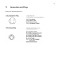
Connectors and Plugs ...............................................................................................36
12
Index...........................................................................................................................37
6
1
Preface
I purchased a Kenwood TS-830S on the used market after passing the ham exam in 2001.
Months before I was searching the internet extensively to get an idea of how an newcomers
shortwave transceiver must look like, especially what features it must have and which of them
are not essentially. The costs did play an important role: my personal limit was 500$ for the
transceiver (a few weeks later the MFJ-949 manual antenna tuner took me again 200$… and an
MC-50 mike from Kenwood again 70$). Regardless of the many (mostly technical) comments
about this decision, which are to be found on the net, my personal opinion is that a transceiver
must look like a transceiver – that means, there must be a minimum amount of metallic shining
knobs and switches and in generally a solid design.
First time using it I didn't really know what I was doing, but the TS-830 knew…and did what it
was expected to do… It didn't take a long time until I encountered the first problems: there was
no output in SSB-mode and I realized the low power output on the upper bands. And here the
story begins. I searched for technical descriptions and procedures to do these repairs and found
them wide dispersed on the Web. And so I started collecting them, in the beginning for personal
use only.
The problem of no SSB TX operation was quite easy to fix: a broken copper ground connection
on the back of the IF board caused the mike amplifier to fail. Soldering a simple insulated wire
to another ground point on this board and I was in business on SSB. Changing the tubes and
re-neutralizing in generally is a simple procedure, but if one had never done this before, even
simple things can be difficult or at least take a long time. This may be a waste of time – on the
other hand its is only the intensive dealing with a problem that makes us learn and achieve
experience and skill.
Many hams do know how to handle and repair older equipment, but a growing number doesn't
anymore since they grew up with solid state technology only or are not interested in the older
rigs. Many newbees are taught to avoid boatanchors, they hear that dipping the plate and
peaking the load of a tube final is much too tricky and time wasting (takes 5 seconds or less…)
to make dealing with these rigs worthwhile.
If You are the proud owner of one of these 20-year old TS-830's made by Trio-Kenwood You
are probably interested in old equipment – if not for liking so for necessity. This collection of
articles and information about the TS-830 should serve as a reference for those who need it. If
You find this file useful, You are invited to propagate it over the net. If You add Your
experience or improve it's content, please email a copy to me. Feel free to remove my name
from the cover page if You want – I'm not the author but only the collector of this stuff. Please
excuse my poor English…
Halle, Germany, June 25th 2002
VY 73's
Olaf Rettkowski DL9AI
Email: [email protected]
2
Read first !
All information provided here is not verified. Use the modifications and procedures at Your own
risk. Please keep in mind, that malfunction or damage of Your equipment may occur, even if
You follow the instructions of these document carefully.
7
Please make sure You have the latest version of this document. Check
http://www.geocities.com/om6523.
3
History of this document
•
First version (1.0) 25th June 2002 by Olaf Rettkowski DL9AI
•
Latest revised version: (1.1) 13th Nov 2002
4
5
To-Do list
•
For part II "Manuals": Rescanning of the layout and the board schemes to make them
READABLE; the additional red lines indicating power supply lines are to be regarded.
•
Adding of general information how to repair a rig: measurement equipment, procedure;
where to start for locating errors – the information provided with the service manual
seems to be not sufficient, especially for those of us not so familiar with sophisticated
electronic repairs.
•
Adding of personal experience in using a TS-830: maybe someone has developed new
procedures or can give hints helpful in operation.
•
Adding of detailed descriptions of the function of certain parts – which resistor or
transistor has what function. This will help not only in fixing problems of this rig but
provide some kind of teaching material to learn electronics…
•
Adding of test reports of older ham radio magazines, (if allowed to publish…)
General Description
(Author: Richard L. Measures, AG6K)
The ancient TS830S is a still a remarkable radio.
Processing: The processor is clean and effective. When an 830 processor is turned on, the Smeter at the receiving end noticeably increases and the perceived volume increases - yet the
audio is clean and understandable. I have never observed a modern transistor-output radio that
could perform this feat. There are several factors at work here. First-off, RF, instead of AF,
clipping was used to maximize the effectiveness of the processor. Naturally, RF clipping
generates IMD products. Trio-Kenwood engineers minimized this problem by utilizing a postRF clipping 455 kHz IF ceramic filter to clean up the IMD products. After the processed
transmit IF signal is filtered and converted to the operating frequency, it is amplified by an
extremely low-distortion tube-type RF amplifier that utilizes [Collins Radio, Co.] RF-negativefeedback. The net result is a clean, effective RF processor that is not objectionable to listen to provided the indicated processing level is kept under roughly 8db.
Strong signal overload: The 830 has extremely low VFO phase noise. When listening to a weak
signal that is 5 kHz away from a strong local signal, the 830 outperforms many modern radios.
However, at signal spacings of 50–100 kHz, modern radios are better at tolerating strong local
signals. On transmit, the 830 generates a remarkably clean transmit signal with a minimum of
adjacent-frequency phase noise.
S-meter accuracy: The 830's S-meter is fairly accurate. Above approximately S-5, one S-unit
equals pretty close to the required 6 db. Above S-9, the db scale is reasonably accurate.
Naturally, calibrating the S-meter helps. Some modern radios indicate 3 db per S-unit--a 50 %
error, and 20 microvolts = S-9. Whatever happened to the Collins standard of 100 microvolts =
8
S9?
Drawbacks:
Slight frequency drift during warmup. This problem can be ameliorated by one of the fixes
described below.
2. Inability to work split frequency at typical frequency differentials.
3. As with any ancient machine, maintenance requires an extra effort. However, newer radios
appear to be far from trouble free. I have spoken with owners who had to return their highlycomplex new radios to factory service five times during the first year.
6
Problems and known Fixes
6.1
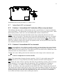
Excessive delay in relay control signal to external amplifier--which
causes hot switching in the amplifier's RF relays
Cause: The RF relay in the TS-830S also switches the external amplifier relay control line.
Thus, the amplifier relays can not begin to close until the RF-relay in the TS-830S has closed.
Fix: Install a NPN >200V switch transistor [MPS-A42 or=] in the TS-830S to take over the job
of relay control line switching. The input [base] of the switch transistor is driven by the +12V on
transmit signal ["RL"] that drives the coil of the TS-830S' RF-relay, RL1. The base-current is
limited to approx. 11 mA with a 1 KOhm series resistor. Connect another 1 KOhm resistor
between the emitter and the base to drain off the stored charge in the base. The emitter connects
to chassis-ground. The collector connects to the wire from pin 4 on the Remote socket. Pin 2 of
the remote socket should be connected to chassis-ground or to the emitter of the transistor. The
NPN transistor can only switch a positive relay-control line voltage, so this circuit will not work
on negative relay-control voltage amplifiers like the SB-200 and the 30L-1. The fix is to convert
these amplifiers to [standard] positive V relay control line polarity. A solid-state electronic
cathode bias switch [ECBS] is useful in this application. Such a circuit is shown in QST
magazine, January 1994, "The Nearly Perfect Amplifier."
6.2
Frequency drift
(Author: Tommy Hayes)
Before making any internal modifications for the frequency drift please try this:
Take both the top and bottom covers of the rig off the transceiver. Find each and every philips
screw that you can get to with a philips screw driver and loosen it about 1/4 of the way. After
doing that, retighten the screws.
9
This includes but is not limited to each and every PC board that you can get to. Done this with
my 830 that had severe drifting problems and so far (4 months) have not had a problem with the
drift yet on any band.
6.3
Frequency drift during warm-up
Cause: Change in humidity and temperature inside the VFO Unit.
Semi-Fix: The amount of frequency-drift during warm-up can be reduced if the radio is
equipped with a "damp-chaser" resistor that will keep the VFO slightly warm when the radio is
switched off. This is accomplished by placing a 7.5 KOhm nominal, 2 W metal-oxide-film
[MOF] resistor in parallel with the contacts of the power-switch, S9. When the radio is off,
roughly 115 VAC appears across the switch contacts, which causes the resistor to dissipate heat
underneath the VFO. The full lead-length resistor is mounted on two, standoff insulators which
are fastened to the shield partition that is between the VFO and the PLL Unit. The resistor is
positioned under the VFO shield-can. A strip of insulating tape is placed on the bottom of the
VFO shield-can and on the inside of the bottom of the 830 cabinet to provide extra electrical
insulation in the event that the insulating coating on the MOF resistor fails. Each resistor lead
should be placed inside approx. 28 mm of heat-resistant insulating-tubing, such as Teflon, so
that the wires can not touch chassis ground.
6.4
TS-830S Frequency Drift - "FIX" switch
(Author: Alan N5LF)
If your TS-830S drifts or jumps frequency up & down 100 to 200 Hz, the problem may be a
dirty FIX switch. The FIX switch disables the VFO and is used for crystal control. The switch
conducts voltage in both the on (crystal) and off (VFO) positions. Dirt, corrosion, or wear makes
the switch provide uneven voltage to the VFO and therefore causes the drift/jumping.
To test for this problem, wiggle the FIX switch or press it in & out a few times and see if the
drift/jumping stops for a few minutes.
Temporary cure: Spray the switch with contact cleaner. This works for me for 1 to 3 months,
then it starts acting up again.
Permanent cure: Use a jumper to bypass the switch, so it is permanently in VFO position.
If someone knows a solution that doesn't disable the FIX switch's function, please let us all
know.
(These and other hints mentioned also in section 6.5, page 6)
6.5
Frequency jumping
Alan Wormser had the problem caused by the FIX switch (see section 6.4, page 9) and also
supplied some other answers to his question:
1. Grounding the AF/AVR board: Connecting a wire from TPG post to ground screw, and
inserting star washers between board and heat sink, in accordance with Kenwood bulletin appeared in QST Hints & Kinks in the mid-1980s. (Ian G3SEK, Art N2AH, Paul K0PW, Frank
Kb0ZFN, and many others)
2. The grounding screws on the PC boards may not make good contact. (Bill W7US)
3. Although I have not seen this problem in a Kenwood, I have seen it in Icom and Yaesu- both
with the same cause- small single turn variable caps. In case of the Yaesu it was a frequency
netting cap on a heterodyne oscillator- drove me nuts. It occurred randomly and never when I
10
had the rig open. A hint from another ham sent me looking in that direction. Replaced 2 or 3 and
that was the end of it. (Dale W4OP)
4. Check the external VFO DIN jack in the rear. Actually you will need to check it from the
inside. If you have one, put the matching DIN plug into the jack and pull it in and out several
times. This is a common problem with the 830. This jack has a contact which is shorted
WITHOUT an external VFO. If the contacts get dirty, it will do exactly as you described. You
might also want to spray a small amount of contact/electronic solvent on the jack and do the
plug in and out. (Brian KJ5AG)
5. I had what sounds like the same problem with a TS-830S. Turned out the FIX switch labeled
was intermittent. It is in the path of the voltage to the VFO and if it has some extra resistance,
the frequency would change. I tried "Deoxit" and that worked for a while but finally I jumpered
around the switch contact since I never used crystals for operating. Try operating the switch
many times and see if goes away for a while. (Dennis NT0V)
6. Maybe one of the xtal trimmer caps is going bad. The center pivot point is getting rusty.
Contact cleaner will fix this for a month or so but you need a new one.
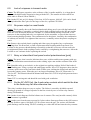
6.6
Intermittent shift in display and operating frequency
(Author: Trio-Kenwood Communication, Inc.: “TS-830 frequency shift”)
Some users may report an intermittent shift in the display and operating frequency. This may
typically be a 1 to 4 KHz random shift. Cause will be a loose grounding screw on the AF/AVR
unit heat sink.
On the AF/AVR unit X49-1140-00, there are three self-tapping screws holding the aluminum
heat sink to the PCB. These also supply the ground connection to that section of the board.
Between the heat sink and PCB foil, add a tooth-lock washer N17-1030-41 at the two selftapping screws on the side of the heatsink that has the two transistors attached. (The remaining
screw already has a lock washer.)
When replacing the board to the chassis, add a solder lug E23-0420-05 to the heat sink
mounting screw as shown, and tighten all screws for this board. Solder an insulated lead
between the TPG (Test Point Ground) wrap post adjacent to C81, and the added solder lug.
Procedure:
1. Remove the top cover (8 screws) and unplug the speaker.
2. Remove the bottom cover (8 screws).
3. Remove 5 screws holding the AF/AVR unit and swing the board over. Leads do not have to
be unplugged.
4. Add two tooth-lock washer as shown.
5. Replace the circuit board and heat sink to the chassis, adding the solder lug as shown.
6. Solder a jumper between the TPG wrap post and the added solder lug.
7. Replace the top and bottom covers.
11
Installation time for this procedure is 1/2 hour or less.
6.7
Intermittent ALC on transmit
6.7.1
Problem 1: Intermittent ALC indication [TX] on only one band
This indicates that the trouble is different than was the case in Problem 2 {which would be the
same on all bands}. The bandswitch is usually the culprit. This occurs most often on the 7 MHz
band-switch position, on the two, rear-most bandswitch sections in the RF Unit.
Cause: The bandswitch (also) has dissimilar-metal crimp-connections that turn into semiinsulators due to electrolysis. This takes place between the bandswitch's riveted-on,, tin-plated,
stationary contacts and the copper-foil on the printed circuit board [PCB]. Fix: Apply a small
amount of conductive-paint where the stationary switch contact touches the copper-foil on the
PCB. The conductive-paint will be drawn, by capillary-action, into the problem area where the
two, dissimilar-metals touch each other.
6.7.2
Problem 2: Intermittent ALC on transmit
Cause: As in problem 1, this problem is usually caused by an intermittent crimp-connection on
the pins at the ends of the coax cable that brings the transmitter intermediate-frequency ["TIF"]
signal from the IF Unit to the RF Unit. The ends of the TIF coax cable can be found in the same
connectors that were discussed above, in Problem 1.
The fix is the same: Make good electrical connections at the crimps on the connectors' pins.
6.8
Lack of crispness in receive audio
Cause: The intermediate-frequency bypass capacitors, C62/C63, at the audio output of the
product-detector, are so large that they noticeably attenuate the treble audio frequencies.
Fix: Reduce the value of these capacitors and reduce the terminating resistance, R78, across the
output capacitor, C63, to reduce the treble attenuation. R78 is changed from 47 KOhm to
approx. 3.3 KOhm - 4.7 KOhm. C62 and C63 are changed from 0.022 µF to 0.0075 µF 0.01 µF. {the factory value varies depends on the radio's S/N} These components are on the IF
Unit, about 4cm in front of the left-rear corner. Note: After this change is made, the full range of
audio frequencies will be present in the background/"sky" noise. It is beneficial to compensate
for this by turning down the RF Gain control until the sky noise decreases to a comfortable
level. [This is the main reason to have an RF gain control.]
12
6.9
Lack of crispness in transmit audio
Cause: The RF-bypass capacitor, at the collector of the 1st audio amplifier, is so large that it
bypasses the higher audio frequencies along with the RF. {The amount of treble-rolloff in a
stock radio is about 4.5db at 2800Hz.}
Fix: On the IF Unit, at Q19, change C106 from .015µF to approx. 0.001µF. Q19 can be found
directly behind the filter space for the larger of the two, optional CW-filters.
6.10
No power output on most bands
Cause: This is usually due to the final unit bandswitch being out-of-sync with the bandswitch
shaft. This problem is caused by a cracked, plastic shaft-coupling between the RF unit and the
final unit. Trio-Kenwood did not use Locktite, or a similar thread-locking compound, so the
setscrews in the coupling had to be over-tightened, by the assembler, to prevent the setscrews
from loosening during operation. The constant stress on the plastic, caused by the combination
of ordinary use and the over-tightened the setscrews, eventually causes the plastic couplings to
crack.
Fix: Remove the cracked plastic coupling and either epoxy it together, buy a replacement
coupling from Trio-Kenwood, or find a replacement shaft coupling made from metal. Use
Locktite in the setscrew threads during re-assembly so that the set-screws will not need to be
overtightened. Plastic shaft couplings can be cracked by overtightening the setscrews. Allow the
Locktite to set 2 minutes before operating the switch.
6.11
Noisy or intermittent front panel control potentiometers [pots]
Cause: The grease, that is used to lubricate these pots, oxidizes and becomes gummy with age,
causes an intermittent connection between the rotating wiper-arm and the resistance-film in the
pot.
Fix: Stand the radio up on its back, on the original rear packing cushion. Pull-off the knobs of
the offending pots. Using a syringe and small-gauge needle, inject TCE degreaser down into the
clearance spaces next to the concentric shafts of these pots, rotating the shafts back and forth to
loosen the gummy grease. When the pot is no longer intermittent, inject GC Electronics Co.
"De-Ox-Id" . This material should be thinned with about 50% TCE to help fluid penetrate down
into the pot.
Note: TCE is carcinogenic and should be used with good ventilation.
6.12
On the AF-AVR Unit, the 4-pole relay contacts which switch the bias
to the finals may fail after extensive use.
This relay is neither cheap nor easy to replace. The failure is caused by th.00000 repeated
shorting to ground of a charged capacitor in the bias circuit by one set of the relay contacts
during T/R transition.
Fix: On the circuit diagram, find the leftmost set of contacts. The arm [movable contact] of this
set of contacts is grounded.
Fix: cut the trace from the arm to ground in 2 places about 5mm apart. Remove the foil between
the cuts. Solder a approx.100 Ohm, 0.25 W resistor across the gap. The resistor will limit the
peak discharge current during T/R-R/T switching to a value that will not burn the relay contacts.
13
6.13
Peak-distortion in the RX audio
Cause: This is usually caused by one or more problems in the product-detector [PD] on the IF
Unit. These problems are: 1. Unmatched PD mixer-diodes, and/or 2. Too-much 455 KHz
injection-voltage at the local-oscillator {LO} port of the PD. 3. No terminating-resistor is used
at the LO-port of the PD. This allow the IF-signal to modulate the LO, which adds distortion.
Fixes: Replace the PD diodes, D20, 21, 22, and 23, with 1N6263, Hewlett-Packard HSCH1001, or similar Schottky-diodes. {D20-24 are on the IF Unit, about 4 cm in front of the left-rear
corner}. Add a approx. 100 Ohm, approx. ¼ W resistor from the junction of R75 and R76 (470
Ohms each) to circuit common. If you have an oscilloscope or an RF-voltmeter, the correct LOvoltage, measured across the added 100 Ohm terminating-resistor, should be approx. 600 mV
peak to peak on both USB and LSB. This voltage can be set by alternately adjusting L19 and
L20, which are about 3 cm northeast of connector-11.
Note: This test point is also available, from the component side of the board, on pin 4 of
connector-11, to circuit common.
6.14
Poor, transmit, SSB carrier-suppression after alignment
Cause: Unmatched balanced-modulator diodes.
Fix: Replace the original, Germanium diodes, D29 thru D32 with 1N6263, Hewlett-Packard
HSCH-1001, or similar Schottky diodes and re-null the carrier with TC3 and VR4 on the IF
Unit.
Note: HSCH-1001 diodes are hybrid-type Schottky diodes, which have a lower noise-figure at
audio frequencies than ordinary Schottky diodes. Ordinary Schottky diodes will also do the job.
6.15
Power-output falls off when the key is held down
Cause: This is usually the result of electron emission from the screen-grids in the 6146Bs.
Screen-emission is caused by operating the filaments of the tubes with excessive filamentvoltage for many hours. The excessive filament-voltage overheats the cathode, which causes the
cathode's electron-emitting barium coating to slowly evaporate and stick to the screen-grid.
When the contaminated screen gets hot during key-down operation, the barium particles on the
screen emit electrons in the wrong direction, toward the cathode, which causes the anode
[plate]-current, and power-output, to fall-off.
Fix: Replace the 6146B’s with new tubes and insert, for 120 VAC or 240 VAC operation, a
0.51 Ohm nominal, 2 W, Metalfilm [MF] resistor in series with the Final Unit PCB-end of the
violet-colored wire, that connects the heater switch to the PCB {that the 6146B sockets are
mounted on}. The added voltage-drop in this resistor will decrease the filament-voltage, at the
tube-sockets, to approx. 6.1V and will greatly prolong the life of healthy tubes without altering
their power-output or IMD.
6.16
Premature 12V pilot lamp burnout
Fix: Reduce the pilot lamp operating voltage. Put a suitable resistor in series with the wire that
supplies power to the pilot lamp terminal strip on the bottom of the radio, near the VFO. Start
with approx. 20 Ohms, 0.5W. For optimum life, the pilot lamps should be operated at roughly
8-9 V. Reducing the voltage to the meter pilot lamp requires a separate resistor of roughly
68 Ohms.
Note: inexpensive replacement lamps are available at hobby shops that sell miniature trains.
14
6.17
Rapid jumps in VFO frequency
Cause(s): [1] This can be caused by fluctuation in the 9V regulated power-supply voltage,
which is the result of an intermittent connection between the AF-AVR [automatic voltageregulator] Unit's circuit-common and chassis ground. [2] The problem can also be caused by a
dirty ground-connection wiper on the rotor of the VFO tuning-capacitor.
Fix(s): [1] Solder a wire to the "TPG" terminal, next to C81, on the AF-AVR Unit. On the other
end of this wire, solder a #6 ground-lug with locking teeth. The ground-lug is placed under one
of the nearby sheet-metal-screws that fastens the AF-AVR Unit to the chassis. [2] Remove the
VFO from the radio using a 3 mm Allen-wrench. Pull the pilot-lamps from their grommets and
pull the electrical plug from the rear of the VFO assembly. Remove the VFO shield-can {5,
Phillips-head screws} and clean the gummy grease from the wiper on the tuning-capacitor's
rotor shaft with solvent. Lubricate the wiper with contact cleaner.
6.18
Receive [RX] signals intermittently drop roughly 40 db
Cause: This is usually due to a poor electrical connection at the crimps on the contact-pins at
the ends of the "RIF" [receiver intermediate-frequency] coax cable, which is above the chassis.
This cable carries the 8830 KHz RX signal between the RF Unit, Connector-5, pin 2, {to right
of VFO} and the IF Unit, Connector-6, pin 6, {to left of VFO}. The crimped-on pins in these
connectors have a tin-plating. The coax has copper conductors which, along with moisture from
the air, creates a dissimilar-metal electrolytic action that eventually turns the crimp-connection
into a semi-insulator.
Fix: Make a good electrical connection between the copper and the tin-plating, where the
center-conductor wire protrudes beyond the crimp, by applying solder or a conductive-paint
{neater than soldering and easier to use} such as GC Electronics Co. Silver-Print. This paint can
be applied to the target area with the end of a partially straightened paper-clip. To remove the
female pins from the connectors, using a jeweler's screwdriver, depress the pin's ratchet-tab,
which is accessible through the slot in the side of the connector and simultaneously pull the
contact and wire out through the back of the connector. To avoid mixups, remove one pin, repair
and replace it before removing the next pin.
Note: It is easier to gain access to Connector-5, on the RF Unit, if the Counter Unit is moved
slightly {4, Phillips-head screws}.
6.19
Receiver AGC-overshoot, causing receive audio-distortion on voicepeaks and concurrent S-meter overshoot
Cause: Too-much R/C delay in the AGC-bus at the second-gate of Q1 on the RF Unit.
Fix: Replace R12 [1M Ohm] with a 10k Ohm to 51k Ohm unit. Q1 and R12 are located at the
front, left of the RF Unit. It is possible to clip the leads of R12 from the top of the circuit board
and install the lower-R unit without removing the RF Unit from the radio. An alternate method
is to remove the AF-AVR-Unit and remove the cover plate that is underneath it. This allows
easier access to the trace side of the RF-Unit circuit board.
6.20
Television interference with the radio transmitting into a 50 Ohm,
shielded termination
Cause: This is usually caused by VHF harmonic energy leaking out through the line-cord.
Fix: Add one or two, µ=850, VHF-attenuator ferrite beads in series with each of the two wires
in the line-cord. It is also helpful to add a approx. 470 pF, 1 KV, disc-ceramic, bypass-to-ground
15
capacitor, on each wire, on the line-cord side of the ferrite beads. If the bypass capacitors are
added, it is advisable to replace the 2-wire line-cord with a 3-wire, grounding line-cord and
plug. The green ground-wire should be connected to the chassis of the radio. This provides a
ground-return for the small 60 Hz AC-current that flows through the bypass-capacitors.
6.21
Receive suffers or goes out after QRO modification
(Author: Frank J. Lukas, Jr., North Ridgeville, OH)
I would like to pass on the problem I had encountered in connection with the QRO modification
to the Kenwood radios TS830S, TS-530S and the TS-530SP. The problem occurs after many
hours of long winded QSO's. It seems that with the increase in the screen voltage from 210 to
300 volts, R37 on the RF unit (#X44-1360-00) heats up tremendously and will change it's value
so greatly that even the receive either suffers or goes out totally. R37 originally is Metalfilm
resistor at 3.3 KOhm and is 1/2 watt. I have changed mine to a Metalfilm as original same value
but have used a one watt resistor. The brand I was able to get was RCA and I suppose there are
better on the market. This is a 2 % tolerance. Three units that I know of have had this problem
that I took care of in this area alone. Two units were TS-830S and one a TS-530SP. Just thought
I would pass that information along for what it is worth.
6.22
Transmitter "talkback"
(Author: Trio-Kenwood Communication, Inc.)
Transmitter "talkback", either with or without a linear amplifier, may be eliminated by adding a
filter at the receiver audio power amplifier.
On the AF unit X49-1140-00 at Q4, cut the 12 V DC B+ line between R47 and C28, and add a
1 µH choke (L40-1092-02) in-line. Add a 0.01 µF cap (C52-1710-36) from the IC pin 1 to
ground, as shown using a 3 mm lug (E23-0015-04) under the IC mounting screw on the heat
Sink.
Installation time for this procedure is ½ hour or less.
16
7
Problems and Hints from Newsgroups
7.1
Beware of high voltage!!!
Speaking of smoke…
Years ago I laid my forearm across the plate connectors of a TS-830 that was in transmit mode
(don't ask why...), 800 V DC plus RF, about 30 watts worth.
Next thing I knew I was sitting on the floor, looking at my arm... the flesh was crawling around
on it's own, quivering. My wife came running down and said "What's wrong, I heard you yell!".
I told her I didn't yell. She said I did!
Assessing the damage, I felt thankful that it was just the right arm, and that it apparently didn't
go through my heart...much. Then I spotted 'em... two little white burn marks on my left index
finger.
73, and be careful, especially around 120/240 V AC, and tube rigs. And, it's antenna season, that
means take special care to know where your power lines are. The typical high-line behind our
homes (4-8 KV) can jump to metal on a dry day so watch it when putting up antennas. Plasma
burns hurt.
7.2
No sidetone when keying CW, VOX doesn't work on CW
(The VOX works on SSB, so the VOX GAIN control is not left in the 'Off' position…)
The sidetone generator is used to key the VOX in CW. On the audio unit board, there is a Q1
that is the sidetone oscillator. Look at TP1 on that board when keying the key, you should see an
audio waveform of several hundred millivolt peak-to-peak there. Or us a digital voltmeter on
AC volts, should see a low-level AC voltage that corresponds to the CW key action. If it's not
there, you either have bad Q1 (2SC945, which every ham should have a couple of at all times!)
or some other component bad. Q1 is a run of the mill audio oscillator.
According to a Transistor data book, the 2SC945 is equivalent to either the BC548, or 2N3094.
Both being NPN capable of handling 100 mA at up to 50 V.
(ATTENTION: success of the procedure is not reported)
7.3
Resistor replacement after grid-to-cathode short of the 6146 tubes
(For TS-520,TS-820,TS-530,TS-830)
On these rigs, if the 6146 tube(s) develop a grid-to-cathode short (the usual mode of failure), the
1 W 10 Ohm cathode resistor will blow, makes noise and smoke. The line fuse resistor may or
may not blow. This resistor acts as a fuse; DON'T oversize it when replacing. Replace both
tubes, and replace the resistor with same size, such as Radio Shack 271-0080.
Hint: Metal film resistors "blow" more cleanly than carbon comp, and break the circuit more
quickly.
7.4
Difference between 6146B und 6146W tubes
The highly touted and easily available so-called "heavy" 6146W actually has less plate
dissipation than the 6146B (25 W for the W-type versus 35 W for B-type). That is why the B
version is so much more expensive. It's not really necessary unless you have done the highpower screen voltage mod on these rigs, but that's another story...
17
7.5
Slow power drop-off
Question: I've been tuning my 830S through a good 50 Ohm dummy in the tune mode and pretuning the antenna tuner in this mode also so I would not damage the finals. The last two days I
have noticed that after warmup, tune and pre-tune of the tuner the power will slowly drop of
from 110 W to nearly 50 W. Another interesting thing, during the tune-up stage, as I max the
drive I noted it would max.. then slowly increase at about 1/4 more than the max. I would then
continue with dipping the plate etc. with 100 to 110 W out. If I held the key on tune or CW I
would peak at 100 then the power would slowly drop to 50 W over 10 seconds. I have not held
the key longer than that… (Glen KD5NVC)
7.5.1
Slow power drop-off: Answer 1
The 830S is now officially an "old" rig, since it was on the market in 1980, some 21 years ago.
If it has the original tubes, it's very likely they're very worn out! Even if it's on its second or
third set of tubes, this is quite likely, especially if the tuning process is ever prolonged.
There's no reason to spend a lot of time tuning up a TS830S. Adjust the external antenna tuner,
if you must use one, with the 830S running very low power in the CW or RTTY mode, where
the power can be turned down to almost nothing. Once the tuner is all adjusted for the best
possible match, run the drive back up and spend the next five seconds optimizing the PA tuning.
If it takes longer than that, you're really doing something wrong. There's no reason to dip the
plate current, etc, that's a guideline.
I used to tune my 830S "on the fly," by simply dialing up a frequency where I wanted to make a
call, pressing the mike button and making the call while quickly adjusting the TUNE and LOAD
controls for maximum output on either the 830's relative output meter or an external wattmeter,
using my voice as the signal. That gets it tuned fine in just a few seconds.
The leading cause of 6146 and 12BY7 failure in the Kenwoods has always been "tuning up."
Keep it brief, and do your adjustments at low power, then a very short touch-up of only the PA
TUNE and LOAD controls (no reason to go back and re-peak the driver stage, it won't change),
and you're done. I'd surely change the 12BY7 and the 6146's, follow the neutralization
instructions in the manual for re-neutralizing the 6146's, put it back together and keep tune-ups
short! They'll all last about ten years if you follow that rule. (Steve WB2WIK/6)
7.5.2
Slow power drop-off: Answer 2
Hi Glenn: If the plate voltage on the finals is not dropping, I would definitely suspect the finals.
Most power tubes begin dying the same way - by losing emission after they have been working
a few minutes. I suspect I have changed a thousand or more of various types from 45's and
6K6's up with that same problem. (Pete AC5E)
7.5.3
Slow power drop-off: Answer 3
My TS830 is in its 20th year with me.... a year and a half ago, I replaced the 12BY7 after
experiencing the same symptom. Touch wood, I'm still on the original finals. Having used tube
finals in my HF rigs since I got licensed 36 years ago (yikes!), I have found the power drop-off
symptom to have always been a dying tube.
By the way, I don't think you have to be overly careful about tune-up - just don't keep the key
down too long, and it can be done fairly quickly. I adjust the load for maximum output, dip the
plate current, then go again with the load for maximum output in my outboard power/swr meter,
and back again to dip the plate current. Each time the dip is less deep, and output power
increases. Hey -- after all these years I still love this rig, which is as comfortable as an old
18
shoe - great audio, a good receiver, and very reliable and rugged. This radio has given me its
money's worth and more so - it's been a worthwhile investment, and I still don't see retiring it -I'm still enjoying it too much!!! (4X1MK)
7.5.4
Slow power drop-off: Answer 4
If I remember correctly, you aren't risking anything by installing your new 12BY7. The last time
a 12BY7 went bad while I was using it, in a Tempo ONE, the current increased (while output
went down?). I didn't live near any place I could get a driver tube, so I tried short transmissions
-- blew the fuse (the fuse protected my rig from ME!) (AE7G)
7.6
Low power output
Question: I recently purchased a TS-830S used, the unit is clean with no evidence of abuse.
After proper tune-up using a Heathkit dummy-load and a good swr/watt meter for HF can get
80 W PEP max. on CW. Specs show that I should get 100 to 180 max on CW. Can this be the
6146B or the driver tube? bias is 60 to 65 mV, I have double checked ALL tuning as per
Kenwood instructions. SSB voice peaks near 60 W PEP max. (Glen KD5NVC)
7.6.1
Low power output: Answer 1
Hi, Glen: It is really hard to make a reasonable guess at this distance. My first suspect would be
the output tubes, since I have had several 6146's "die slowly." The 12BY7 usually goes out
pretty quickly. (Pete AC5E)
7.6.2
Low power output: Answer 2
The TS830S runs 100 W-120 W output power, depending on the band (~120 W on the "lower"
bands, fading to about 100 W on 10 m). So, you're not far off.
You say the "bias is 60 to 65 mV," which makes no sense at all. Do you mean the idling plate
current, created by the bias, reads 60 to 65 mA? That would make sense. And if so, that's a bit
low. It's normally about 90 mA, and is adjustable with the bias control on the rear panel. If you
crank that control and cannot get the idling plate current to increase above 65 mA, then I would
definitely suspect "soft" 6146's, either one, or both. You can tell if the 12BY7A driver tube is
good by looking at the ALC meter. When in TUNE, you peak the driver tuning control (which is
grid tuning on xmit, and receiver preselect peaking on receive) for a peak in ALC reading, and
then you can adjust the drive up and down with the drive level control (potentiometer), which
only works on TUNE and CW and does nothing in the SSB mode. When in TUNE and after the
driver stage tuning is peaked, see if you can turn the drive level control up so high that the ALC
meter "pegs" (goes offscale to the right). If so, the 12BY7 is probably okay. When they go soft,
it's hard to get the ALC meter to read very high. (Steve WB2WIK/6)
7.6.3
Low power output: Answer 3
Look at the specs again. I suspect, and I may be wrong, but it may say 100 W to 180 W "input
power" on CW..... The radio transmitter being 60% to 70% efficient would come out to 60 W to
120 W output. All of the old radios measured power in the terms of input power, not output
power because that is the way the FCC power regulations of the time read....75 W input power
for a novice, and 1000 W input power for general and above. Even my Kenwood TL-922
amplifier says 2000 W input power. (Kenneth AB5CC)
19
7.7
Intermittend drop of power output
Question: …I seem to have intermittent problems with the power output. I typically would peak
the RF output in CW mode, at approximately 265 mA plate current, and see roughly 130 W
output on my less than state of the art MFJ-949E tuner. One day after a successful QSO and
excellent 59 +20 signal report from Turks and Caicos Island on 14.203 MHZ (I'm located in
Cincinnati, OH), I moved up to about 14.310 and when I tried to retune, found that I read only
about 30 W on my meter…
…After installation and neutralization of new final and driver tubes, I'm not sure if it is working
properly or not. In CW mode, at 265 mA plate current, I show about 35 W on the average
reading MFJ meter. In USB mode, if I whistle into the mike with mic level conservatively set at
about 12 o'clock (into a dummy load of course) I seem to get up to about 80 W... (Rick
W8RDH)
Answer: I had the same problem with my TS-830S. The power started dropping to 75 W, then
finally got down to 30 W. I also assumed that the final tubes were going bad, so I bought a new
pair, along with a driver and re-neutralized. Everything worked good for about a day before, I
dropped back down to 30 W. After doing some hunting around, I found that a wire that
originated by the 12BY7A tube area and ran to a pin that was insulated on the tube cage
shielding area, had a bad soldering joint. After resoldering the wire to the pin, the problem has
not come back.
Another thing you might want to look into, is that your coax jumper cable between the rig and
tuner does not have any shorts. Just recently, we were setting up a club station, and we were
only showing 30 W output from a Ten Tec Corsair II at the tuner/dummy load. Turned out to be
a bad jumper, because when it was replaced we were getting 100 W out. (Mark K9MQ)
7.8
Problem peaking Drive control
Question: The tune-up procedure for this rig begins, after setting Bias for 60 mA, with setting
the mode switch to Tune, meter switch to ALC and using the Drive control to peak. I have done
this hundreds (thousands?) of times in the past, but now when rig is switched to send, the meter
initially rises as expected, and then quickly drops to zero, with about a 30% drop in output
power as indicated on my power meter on 20 meters. Subsequent tries result in progressively
lower initial ALC readings. On 15 meters, I get no ALC indication at all, but seem to be able to
tune the Load, Plate and Drive controls for max power out. (Rick W8RDH)
Answer: Replace the 12BY7 driver tube and that should fix it. A weak driver tube will cause
low ALC action. (KF4DHE)
7.9
Intermittent loss of drive to final
Question: The rig has been out of service for a couple of years. Usually I get 1 W or less power
out. New Finals and drive tube. Occasionally works fine for hours then power goes back very
low. Meter shows NOTHING in tune position. I tried contact cleaner on switches, relays, etc.
(Jess KR4OJ)
Answer 1: I've had my used TS830 for about a year, and just encountered this symptom for the
first time. When in Tune mode and the meter switch is set to ALC, I got NOTHING on the
meter, whatever the CARRIER level setting. Then, after wiggling the DRIVE control, I saw the
ALC reading jump around. I took the cover off and sprayed contact cleaner on the variable cap's
rotor wipers. I then saw the correct ALC, but changing to CW & Ip on the meter produced
jumpy readings. I repeated the contact cleaner, which worked the second time. So check the cap
in the driver plate circuit. (John W0GMJ)
20
Answer 2: Check the driver valve base soldering under the RF board, I had the same problem
and found hair line cracks in the soldering of the base connections, also there are a couple of
resistors and a two pin plug to check right next to the base of the driver valve well if that doesn't
work check the last wafer switch, for bad contacts.
Answer 3: I found on mind this happens on the 18 MHz band along with a loss of receive on
that band. Cleaning the band-switch -- I think the last or second last wafer before the final cage
temporarily fixed the problem, and a longer lasting fix was obtained with lightly applying "RailZip" to the slider, which overcomes oxidation improving contact. This is available in model
railroading shops for improving contact on electric train tracks to the engine. (Ron 4X1MK)
7.10
No dip on the plate current and no or small output
Question: Alas... my venerable 830 serving me for the past 19 years got sick...
No dip on the plate current on any band, and just on 40 m I could get some output, but without a
dip. Changes tubes, cleaned the contacts on the bandswitch wafers (this helps for an intermittent
problem on 18 MHz, where there must be some stubborn dirt which reappears from time to
time), to no avail. (Ron 4X1MK)
Answer: With the cover off the 6146's compartment, I turn the plate tuning knob and see that
the final tune capacitor goes pretty slowly for how much I'm turning the knob... hmmmm.. that
vernier drive certainly has geared things down a lot... then... EUREKA !!!!..... I see that for a
full half revolution of the scale on the front panel, the plates only have moved maybe 20
degrees... so I tightened the two Phillips screws on the shaft coupler, which had become quite
loose over the years, aligning the plate tuning scale with the capacitor meshing, and everything
works again as it should. Very simple mechanical problem. (Ron 4X1MK)
7.11
Reducing power output to QRP-like levels, No.1
On SSB, turning down the mike gain is a very poor way to reduce output power because doing
so defeats the transmitter's ALC system. Thus, when you turn down the mike gain, you cannot
assure any particular peak output level, and you're also turning down only the voice modulation
content of your signal; the original carrier suppression, unwanted sideband suppression,
miscellaneous transmitted noise, spurious and so forth are not adjusted "down," at all, but
remain as they were. As such, signal quality overall suffers. The best way to "turn down" the
power of a TS830S - and many other rigs of that vintage that have no power level control on
SSB - is via the external ALC port on the rig's rear panel. Providing an adjustable bias level to
that port, ranging from 0 V DC to –10 V DC, will allow full-range power adjustment, down to
zero output. This is easily accomplished with a 9 V transistor radio battery (be sure to wire the
"+" battery terminal to chassis ground - the ALC voltage supplied must be negative) and a
1000 Ohm potentiometer wired as a voltage divider.
Tune up normally with the pot adjusted for zero voltage at the ALC terminal, and you should
have about 100 W output. With the key down, now turn the pot until the power falls off to
whatever power output you desire. Then, switch to SSB and your output will be that reduced
level. DO NOT RETUNE anything on the rig, its tuning will be just fine. This is the way I
adjusted to output power of my TS830S for many years, it works perfectly and still provides all
the normal audio punch and clarity, but at reduced output power. (WB2WIK/6)
7.12
Reducing power output to QRP-like levels, No.2
The MIC and CAR controls are used for adjusting power output. The meter circuit is not
especially helpful in measuring SSB power, so an outboard PEP reading wattmeter comes in
21
handy. It is okay to tune up in the normal manner and then reduce power. Yes, you always want
the plate current dipped.
Running reduced power on CW has no effect on the quality of the signal. On SSB, turning down
the MIC gain to reduce power can sometimes make the transmitted audio sound thin or wimpy,
as a result of under-driving the audio stage. This is common in older rigs where no other
provision was made for reducing SSB power output. I find that the speech processor can
compensate for that and help fill the signal out nicely, even at lower power outputs. It's been
said the TS-830 was one of Kenwood's finest achievements. I gotta agree, it's truly a pleasure to
operate and has the looks of a serious piece of gear. Mine has been in operation since 1981 and
is still going strong! (Mike W8MW)
7.13
Increasing power output / QRO-modification, No.1
I don't think you'd want to do that... !
Reasons (having owned two TS-830S's over the years, and liking them a great deal):
-
Power supply can't handle it. Transformer is rated 200 mA ICAS on the HV winding. To
yield 190 W output, Ip (plate current) would need to be 365 mA (at 800 V, to create 292 W
PEP input power, required with 65% efficiency to yield 190 W PEP output).
-
Replacement power transformer = big bucks and not readily available.
-
6146 anode dissipation rating will be greatly exceeded. The ICAS PEP output rating of a
6146B in ICAS service with highest Ep (plate voltage) (800V) is 50 W in class AB2.
-
Transmitted IMD products will suffer greatly. In order to provide 292 W PEP input power, a
Ig needs to be >10mA, rendering a non-linear amplifier, per the dynamic curves on the RCA
data sheet.
In all, not worth having a dirty, distorted signal that is rapidly aging the power transformer for a
ca. 3 dB increase in signal strength.
Yaesu used three (3) 6146B's in the FT102 and created one of the lowest IMD transmitters ever
measured (ARRL test lab results), but by doing so they did not increase output power. They
improved linearity, and it sure worked. (WB2WIK/6)
7.14
Increasing power output / QRO-modification, No.2
You would have to raise the plate voltage by 150 V or more. The stock power transformer could
be tapped to do that, but there is no easy way to add iron to the core to support more flux density
for the resulting increase in current, so a new xformer is in order. Also, higher voltage ratings on
the filter caps now would be necessary, and higher than 450 V is difficult to come by, and would
be expensive. Then you need a higher audio level input to take advantage of your new "clout",
so count on spending some time and money there. You may well need a new cabinet to hold
these additional "beefed-up" components. There are other components that may have to be
"beefed-up" as well - e.g., what is the safe power rating on your changeover relay? Of course,
you will need access to a good o'scope so that you can insure that your output waveforms
remain linear and harmonic content has not increased.
When you have put in all this extra time, money, and effort, consider that the payoff is less than
3 db, (at best) or about half a standard "S" unit. Now you can see why you have not run across
an "easy" way of doing this. On the bright side, a brand-spankin' new AL-811 will net you 600
honest W PEP for about a dollar a watt, for a 1 and 1/2 "S" unit increase, and I have seen a
number on the used market for little more than half that amount. A "full gallon" (plus at least a
reasonably efficient antenna) would pretty much guarantee that you could work whatever you
could hear, but if you want that kind of communications certainty, why not use the telephone? (I
22
expect some razz on that last comment by die-hard DXers and contest fanatics, but in truth I
have had just as much fun operating 20 m CW with a 5W OHR 400, although DXCC takes
longer than a weekend!) Best bet for a cheap and easy 2-3 Db boost is to improve your antenna.
Check out the "double-extended zepp" type dipole, or consider one of the new mini-beams if the
$ is there. (NZ5L)
7.15
Intermittent loss of audio
Problem: Unit transmits, and tunes up. I can tell from the meter that it is receiving a signal. I
just loose the audio. Sometimes when I turn it on it works for a while. Sometimes if I smack it
with my fist it works. Sometimes if I rock the On-Off switch it comes on. And yes I have tried
the headphone jack and external speaker jack…(Lance KC0KBL)
Answer: Before you send it off - take the covers off and snug down all the pc board mounting
screws. Don't put the hurt on them, just a tenth of a turn more than finger tight is about right.
Unless you have extra strong fingers, in which case finger tight will do. Several of my friends
with Kenwoods have fixed baffling intermittent problems that way. (Pete AC5E)
7.16
Final tubes replacement and neutralization
Question: My manual is a little vague on the topic of replacing finals and neutralization. Does
this unit accept 6146A's as well as 6146B final tubes? Can anyone give me detailed steps in
neutralization without an RF voltmeter? The manual suggests that when tuned up to 28.5 MHz
"if an RF voltmeter is not available, tune for minimum S-meter reading." I am unclear about
MODE and METER setting when this is attempted. (Michael KN6JQ)
Answer: 6146A's or 6146B's (as well as 6146W's and S2001's) will all work, but tube changing
does require re-neutralizing. The "tune for minimum S meter reading" requires a second
receiver, it's not referring to the S meter in the TS-830S. MODE should be TUNE or CW (key
closed), filaments must be ON, but screen voltage should be OFF (rear panel selection). I've
never found the "S meter" thing to work very well, the signal can be way too strong on any kind
of reasonably sensitive receiver in the same room.
In lieu of an RF voltmeter, any VTVM or FETVM with an RF detector probe will work, and an
RF probe can be home brewed for a couple of dollars (diode, resistor, capacitor). Also an
oscilloscope having response in the HF region (30 MHz) works fine in lieu of the RF voltmeter.
Lacking any of the above, I'd find a local Elmer who has such instrumentation and get help. It's
an adjustment that only needs to be made when changing tubes, which with any luck is maybe
once every ten years, and it's worth the effort to get it right. (Steve WB2WIK/6)
7.17
Low power output on 160 m only
Question: I have a Kenwood TS-830S which puts out 100 W plus on all bands except 160, this
is into a dummy load. Does any one have an answer to my problem? I haven't check out the
tubes yet thought I would see if there was a reason out there, other then the tubes on this band
with the TS-830S?
Answer 1: Do a calibration as outlined in the TS-830S manual. This should peak the power up
on 160 m. (VE3NYZ)
Answer 2: It wouldn't be the "tubes" causing this problem, ever. It's likely someone has diddled
with the alignment and loused it up, or possibly (less likely) a component failure. You didn't say
how much "less" output you have on 160 m. Is it 90 W? 50 W? 10 W? Normally, with factory
alignment and all good parts, the TS-830S actually has its "most" output on 160 m. I used to get
23
~120 W on 160 m, and closer to 100 W on the other bands, trickling down to about 90 W on
10 m. (Steve WB2WIK/6)
7.18
Crystals for FIX band selection
Question: I have a Kenwood 830S with a "fix" selection on the banc switch. This I am told is a
fixed freq determined by a crystal that I can add to the unit. I think it is a 25/U type but no sure.
My question is...where can I find a distributor of these types of crystals. (Glen KD5NVC)
Answer: You only need to provide them with the frequency you'd like to operate on (not the
crystal frequency), and the make and model of the equipment, e.g., Kenwood TS-830S, and they
do the rest. They know how to cut the crystal based only on that information. Such crystals are
not "stocked," they are made to order, but only take about one week. (Steve WB2WIK/6)
7.19
Changed DRIVE setting after final tubes replacement is normal
Question: I have a Kenwood 830S that had "soft" tubes, their output was down to nearly 40
watts at best on all bands. I replaced the driver and both final tubes then as per instructions
neutralized the 6146B's. I now have full power output on all bands but one interesting thing was
noted. Before the replacement, the "drive" control was normally set from 10 o'clock to 2 o'clock
for max. output. Now the range of max output has shifted to 12 o'clock to full clockwise
rotation. My question: Is this normal? I left the unit on for 12 hours, tuned up again and the
driver control is still at the 12 o'clock to full clockwise rotation for max. output during tuning.
(Glen KD5NVC)
Answer 1: I think you are referring to the amount of drive you are applying (the actual drive
control as opposed to the tuned circuit of the driver), and if so it is perfectly normal. The old
tubes would not respond as well and the tendency is to keep pushing the RF into the tubes to get
as much as possible out. Had you have looked closely at the RF envelope, you probably would
have seen some major flattening of the envelope at the 2 pm drive level. By the way,
congratulations on neutralizing the new tubes, a very important step. Many of the 6146 users
never do that - a BIG MISTAKE! (KL7HF)
Answer 2: I don't have a TS830S to look at, although I owned one nearly 20 years ago. I seem
to recall that "DRIVE" control (upper right corner of front panel) doesn't actually increase or
decrease drive per se, but tunes the driver stage to the PA tube grids, and is, in effect, a driver
tuning control. Thus, its position (2 o'clock, or 12 o'clock, or whatever) is based on tuning the
driver to resonance, and has nothing whatever to do with increasing or decreasing any bias level.
Its position would naturally change every time the tubes are changed, and neutralization is
readjusted. (Steve WB2WIK/6)
7.20
Difference between TS-830 and TS-830 "gold label"
Question: What is the difference between them and the plain ol' 830s? (WK0F)
Answer: I have had an 830 since 1981 and in all those years I have never seen any thing (ads,
reviews, etc.) that indicates any difference between them. An 830 is an 830 as far as I know! It's
a great radio and mine still has the original finals and it's been used a lot. good luck on your
purchase. (W8CAR)
7.21
Microphone impedance matching
Question: How can I match a microphone that measures 200 Ohms to my TS-830S that wants
50 K input? (K2EL)
24
Answer 1: Have you tried it as is yet? Generally the problem is with a hi-z microphone when
driving a low-z input. You have the opposite condition so it will probably be fine. You'll just
want to check that your frequency response, modulation and fidelity is ok on the air. (K5DVW)
Answer 2: As noted, the combination of a high impedance mike and a low impedance input
often causes problems. The mike thinks its output is shorted, and does not work well. (A well
shielded audio transformer, or any of the cheap kit preamps around will do a fine job of
matching everything so it works.)
USUALLY any problems caused by a low impedance mike and a high impedance input can be
solved with a resistor across the mike terminals in the plug. The mike sees an acceptable load,
the amp doesn't care as long as it has some voltage to amplify. If you have problems try
something on the order of 470 Ohms to 1 kOhm - it should work fine. Although you may have
to turn the mike gain up a tad. (Pete AC5E)
7.22
Problem with TS-830 TX relay
Question: the TX relay "chatters" on all modes including tune. The relay chatters during
transmit only. The receive seems fine. (Terry N8CDN)
Answer: The relay is in a socket that is in the inverted position and after many years of use it
can work it's way out of the socket. I used to work a lot of AMTOR and my relay fell out of the
socket one day! The relay might be loose in the socket with a poor connection on the transmit
side. Simply open the TS-830S up, find the relay and go ahead and completely remove it.
Inspect the terminals for the dreaded green stuff and if it's there clean it off. Replace the relay
and check operation. (N4ZOU)
7.23
No operation on WARC bands
Question: Transmits fine on all bands, except 18 MHz and 24 MHz, where I get absolutely 0
power out. Does anyone know if this radio needs to be modified or have something special done
to work in those bands, or know where I should go from here? (Jeff WO5D)
Answer 1: The earlier TS-830's had to be modified for WARC (30 m, 17 m, 12 m) TX. (Mark
K9MQ)
Answer 2: I have a TS-830S and had a similar problem. My radio had no output on 30 meters.
It was because the band selector switch was out of adjustment. (Dave W8DEP)
Answer 3: There is a wire under the chassis that you have to clip, then the WARC bands will be
activated. I have a copy of the manual, if you'd like I could scan that page from the manual and
e-mail it to you. I think you're going to like your '830. I've had one since 1987 and I still think it
has the best receiver I've ever heard.(Steve K0SR)
Answer 4: The wire probably needs to be cut. These rigs were manufactured before the WARC
bands were officially opened. This way Kenwood could still manufacture them without
violating FCC regulations. By the way, you are very very lucky to find a rig that hasn't yet been
modified. Probably, it doesn't have a lot of operating hours on it. I also agree it has one of the
best receivers ever built. I often think about getting a newer rig, but that would mean I would
probably put the 830S on the shelf and forget about it. I like it too much to do that, so the new
rig will just have to wait. (Bob N2WSO)
25
7.24
Receiver signal attenuation when keying the microphone or rocking
the bandswitch
Question: I have a problem with my Kenwood TS-830S. After tuning up, when I key the
microphone, the receiver signals are sometimes greatly attenuated. When I rock the bandswitch
slightly, the signals come back at normal reception / sensitivity levels. I think I recall there was
a somewhat common problem with the bandswitches in these rigs. Or is this just a matter of
getting a cleaner on the bandswitch contacts. Any suggestions on what might be causing this,
and how to fix this? Also, any recommendations on a specific brand of contact cleaner to use for
switch contacts / potentiometers in general? (George N0GH)
Answer 1: Tech Spray and GC make some good contact cleaners that seem quite nondestructive in general, and I've had good luck with them. They are available at many
TV/electronics repair/parts shops. Be careful when using any kind of contact cleaner with these
bandswitches, though. It's easy to do more harm than good, and some "horror stories" have been
reported. Might be best to try to isolate the particular section of the switch that's causing the
problem, using a small insulated stick (like a thin wooden "Q-tip," using the non-cotton end) to
gently press suspect contacts on the switch against the rotor of that switch section. If you can
find the specific wafer, or side of a wafer, that has the problem, possibly the bad contact can
simply be pressed back into proper position, or very gently cleaned using a Q-tip and isopropyl
alcohol, which seems pretty benign. (Steve WB2WIK/6)
Answer 2: Another likely candidate in the 830 for the type of problem you describe is the
transmit/receive relay. Pop off the clear plastic cover after unplugging it and gently clean the
contacts. Be very careful not to bend the reeds. A high resistance from a dirty contact here can
really attenuate received signals. A business card soaked with contact cleaner or alcohol works
nicely. Don't use anything abrasive. (K0RS)
7.25
VOX trip problem
Question: I recently acquired a TS-830S. I have made a few "enhancement" mods for CW but
have one problem that still needs a fix. When moving the mode switch between CW-W and
CW-N, the VOX frequently trips, even with the VOX gain in the minimum position. I know of
two other 830 owners that have this problem and live with it. I work 95% CW and the problem
is annoying so I would rather fix it. My initial inclination is to reduce overall gain of VOX amp,
regardless of impact on SSB VOX operation, but this might be taking the wrong approach. I do
not own a scope, so I am flying blind re transients. (N4EX)
Answer: I used to have the same problem with my TS-830S and was able to cure it by cleaning
the mode switch several times. This is easier said than done. The switch is pretty tightly sealed
and cleaning requires locating an opening into the case and injecting cleaner into the switch.
Operate the switch gently through all of the positions - 20 to 50 times is not too many, and let
the rig sit overnight to dry out. I apologize if this response seems overly simplistic, but time
takes it's toll and I've seen a lot of strange symptoms fixed by elimination of dirt, oxidation, and
poor connector contacts. (W8RDH)
8
Maintenance Procedures
8.1
VFO Lubrication
The factory does NOT lubricate the VFO tuning-shaft's concentric bushing-bearings or the
VFO-gearbox. In time, this will cause premature wear and play in the drive system. After
26
removing the VFO from the radio, {see section 6.17, page 14, Fix 2} the VFO drive system's
gears and bearing surfaces should be lubricated with Tri-Flow, Break-Free or a similar, nongumming lubricant, applied with a small watercolor brush. This procedure should be done once
when the radio is new and once every approx. 5 years thereafter.
Note 1: WD-40 and LPS are not non-gumming products.
Note 2: It is easier to lubricate the bushing-bearings on the main tuning shaft if the VFO is
stood-up, face down, on its tuning-knob, so that the lubricant will run down into the concentric
bushing-bearings. Put one of the original foam packing cushions between the front of the radio
and the table so that the knob can not touch the table.
8.2
Fan Lubrication
The fan should be lubricated yearly with a few drops of 10W or 20W oil, placed on each of the
two, felt oil-wicks which are accessible through the oil-holes on the fan-motor. Mobil-1
synthetic, engine oil or Hoppe's #1003 oil works well for this purpose. Ordinary, SF / SG-grade
engine oil will also do the job. The fan is accessed by removing the 4, round-head sheet metal
screws. The dust that accumulates inside the Final Unit should be blown-out with an air-hose
while the fan is removed. When replacing the fan, tuck-in the fan-motor wires so that they will
not touch the hot, rear-most 6146B.
8.3
VBT [Variable {selectivity} Bandwidth Tuning] Oscillator Alignment
[approx. 8375 KHz]
The reason for performing this alignment is that the VBT-oscillator aligns the cascaded SSBfilters so that the 455 KHz, 2nd-IF filter's passband-"window" will align perfectly with the
8830 KHz filter's passband-"window". Correct alignment makes the radio sound good on
receive and transmit, like it was designed to. It also allows the VBT-control to function
properly.
Someone may ask: Why not set the VBT oscillator to 8375.0 KHz and forget it?. If the two,
filters' center-frequencies were exactly on-frequency, setting the VBT oscillator to 8375.0 KHz
would work well in all cases. However, since the combined, center-frequency error-difference of
the two filters can be as much as 300 Hz off, the VBT oscillator's frequency should be customset to match the particular filters that are in each radio. The potentially excellent selectivity
performance of the 830 hinges on this alignment. It requires an external frequency-counter, a
10:1 probe and some patience.
Alignment Procedure Theory: When the VBT-oscillator adjustment [TC2 in the left-rear
corner of IF Unit] is set correctly, the combined filter-bandwidth of the two, SSB-filters will be
maximum when measured at the approx. minus 4S-unit rolloff-points. In other words, the filters
are working in perfect concert and they are optimally reinforcing each other's selectivity skirts.
The minus 4S-unit points are found by tuning the receiver to the high and low edges of the
passband-window. If a spectrum-analyzer and a sweep-oscillator are available, the alignment is
easy and fast. Since most of us do not have access to such costly test equipment, the alignment
procedure described uses the trial and error method of setting the VBT-oscillator. The end-result
is the same with either method: The VBT front-panel control will function perfectly.
Alignment Procedure: Set the TS-830S to LSB, Calibrator to on, RF-gain to maximum, AGC
to fast, VBT to normal , Audio Gain to 2, and IF-Shift to "0". Plug the external-counter into the
headphone jack. Tune the TS-830S to a 25 KHz calibrator frequency plus 1 KHz, until the
external-counter shows approx. 1000 Hz. The S-meter should indicate S8 to S9. Tune the
receiver higher in frequency until the S-meter indicates S4. This is the upper-frequency, approx.
4S-unit rolloff-point. Write down the frequency reading on the external-counter. This frequency
27
should be roughly 3100 Hz. Tune the receiver lower in frequency until the S-meter indicates S4.
This frequency should be roughly 150 Hz. Write down the reading on the external-counter. This
is the lower-frequency rolloff-point. Subtract the lower-frequency from the upper-frequency.
This is the total, minus 4S-unit bandwidth of the receiver, for the particular frequency that the
VBT-oscillator is set to.
The next step is to measure the VBT-oscillator frequency. Connect the external-counter to test
point 1 [TP1] and circuit-common at the rear of the IF Unit, using a 10:1 probe. Write this
frequency [8375 KHz ±300 Hz] down next to the total bandwidth that you just finished
calculating from your two, previous, frequency measurements at the minus 4S-unit rolloffpoints. This particular setting of the VBT-oscillator may or may not be the best one. The only
way to find out if it is correct is to experimentally adjust the internal, VBT-oscillator
adjustment, TC2, either higher or lower, by 50 Hz, and re-measure the total bandwidth at the
minus 4S-unit rolloff-points. If the bandwidth gets wider with the new VBT-frequency, you are
headed in the right direction. If the bandwidth gets narrower, go in the other direction. If it gets
narrower in each adjustment direction, the original setting was the correct one. Each time the
VBT-oscillator is re-adjusted, you must connect the counter to the headphone jack. and remeasure the bandwidth at the rolloff-points. It usually takes about 4 or 5 measurements to homein on the optimum frequency setting for the VBT-oscillator.
When you get close to the optimum setting, it may be best to go in 25 Hz increments so that you
don't overshoot the optimum frequency. In most cases, the best frequency setting is within
±150 Hz of 8,375,000 Hz. Once you have found this frequency, it is useful to write it down on a
self-stick paper label and place it on the inside of the rear panel of the radio, near the VBToscillator adjustment, so that you can quickly re-align the VBT oscillator in the future without
having to go through the trial and error procedure.
Note: Early production 830s, with serial numbers below approx. 3…, used a muRata CFJ455K5
for the 2nd-IF filter. This filter was upgraded to the CFJ455K12 sometime around the beginning
of the approx. 3… serial number production. This superb filter is the same filter that is used in
all TS-940s and all late serial number TS-930s. The muRata …K12 filter was recently replaced
by the …V12 filter.
Before going through a VBT alignment, you may wish to check your filter number. If your radio
has a K5 filter, you can upgrade to the K12 filter. The Trio-Kenwood part number is L72-033305. Kenwood dealers do not normally stock this filter. However, it can be ordered from the TrioKenwood Service Department.
8.4
USB/LSB Carrier Oscillator Alignment
Stand the radio on its left side. Set the AGC to fast, Calibrator to on, RF-gain to maximum, IFShift to zero, VBT to normal and tune the radio to zero-beat the Calibrator on one of the 25 KHz
check points. The S-meter should quiver slightly as the radio is tuned through zero-beat. This is
very close to the point where the 100 Hz {right-most} digit blinks between a "0" and a "9". The
S-meter should indicate about S2 to S3 at zerobeat. If it does not, adjust the appropriate carrieroscillator adjustment through one of the access holes on the bottom of the radio. Switch to the
opposite sideband and repeat the procedure.
9
Modifications
9.1
AMTOR modification
1. Remove C500 (4.7 µF) on the signal board (located top center near connector 30).
2. Ground the junction of R-476/Q-100.
28
3. This will provide a very noticeable decrease in switching time.
9.2
WARC modification
In early TS-830's, the WARC transmit was not enabled. Solder a jumper wire from Pin 12 of IC23 to ground on the DIGITAL UNIT PCB. Ground can be obtained at Pin 8 of IC-4. (KF2TZ)
9.3
RIT / XIT modifications
(from Ed Sanders W4XC, QST Jun 1982)
To extend the RIT/XIT control tuning range to +/- 8 kHz, two ¼-W carbon-composition
resistors are needed. A 160 Ohm resistor is placed in parallel with R17 (6.8 kOhm), which is
located at the rear of the RIT/XIT control potentiometer. R87 (10 kOhm) is paralleled with a
2.7 kOhm resistor. This can be done without remove the AF board by connecting the resistor
between the right side of VR2 and the terminal marked TPG.
Recalibration RIT control is accomplished by centering the control knob and noting the
frequency displayed on the readout. Turn RIT on and adjust VR2 until the frequency noted
previously is displayed.
9.4
VFO-230 fine tune mod
A note published in your t/k newsletter of January 1983, issue no. 30, concerning a fine tuning
mod for the VFO-230, impelled me to purchase a new VFO-230 for the sole purpose of
obtaining a slower dial tuning rate for my TS-830S. then the combination of a defective new
VFO-230 and some bad information in your newsletter note triggered many, many hours of
frustration and irritation over a period of several months starting in June 1986. I believe you
should know about it when information in your newsletter causes frustration and irritation.
I decided to try the diode cutting bit again. It did not work. The optical dial encoder went crazy.
I was ready to explode and did. Fortunately there was nobody around to hear me. Back to the
drawing board. Now I know practically nothing about optical encoders but I do have an
engineering background so I spent some time staring at the VFO-230 schematic in the TS-830S
service manual. Suddenly the light came on. KA0NNF gave you the wrong information about
which diodes to cut. (His call is not WA0NNF as given in your newsletter note. I tracked him
down by telephone. He told me he had sold the VFO-230 and couldn't remember.)
The proper diodes to cut for 6-1/4 KHz per dial revolution are D19, D20, D22, D23, D24, and
D26. I presume cutting diodes D19, D21, D22, D23, D25, and D26 would also work but I will
leave that for someone else to try. In other words, of the eight diodes, cut all but D21 and D25
or D20 and D24 for 6/14 KHz per dial revolution.
That’s the end of the story. My VFO-230 now works perfectly at 6-1/4 KHz per dial revolution.
This permits me to use the excellent TS-830S receiver on 160 m CW with very extreme IF
(250 Hz) and external audio (50 Hz) selectivity. Incidentally, I wonder how many repair
facilities (including yours) are equipped to motor drive the VFO-230 dial shaft at 300 rpm while
observing the optical encoder waveform? this alignment procedure is necessary, and is
prescribed in the service manual, before you should expect the encoder to work at slower than
the "stock" rate. (I think this was part of the problem).
9.5
TS-830S Low Voltage Supply Optional Improvements
(Author: Trio-Kenwood Communication, Inc.)
29
Power supply drift and stability may be improved by these optional component changes and
additions.
On the AF AVR unit X49-1140-00 (Vicinity of Q27-Q30) change:
R124 from 1K to 1.5K (RD14CB2E152J)*
R127 from 470 to 390 (RD14CB2E391J)*
R130 from 47K to 33K (RD14CB2E333J)#
D25 from WZ-061 to XZ-053 (V11-4101-60)*
(*This will improve temperature drift from a maximum of about 100 mV to a maximum of
1 mV, and may be applied to any unit before serial # 201xxxx.)
Add two 22 KOhm ½ W resistors (RD14CB2E223J0, one each across Q30, and Q34, collector
to emitter.#
(#This will improve overall stability and may be applied to any unit before serial #105xxxx.)
Note: These changes are at the owners option and may not be performed in-warranty.
9.6
Kenwood TS-830 filter modification
Here is an easy filter modification for the Kenwood TS-830S. First to use this mod, your rig
need the YK-88C and to make it even better, the YG-455C installed. In short what we are going
to do, is move around a 9 volt switching voltage. This voltage comes from the AF board,
connector no. 7, pin no. 5. Its marked RLR on the schematic. This voltage ends up at the PLL
assembly, connector no. 8, pin no. 2. Please do try this modification by cutting in this circuit at
he source, because this same switching voltage feeds the IF SHIFT circuit, and the VBT circuit,
and the PLL. So cutting the wire at the AF board will make the PLL unlock when the mode
switch is anywhere but in the CW positions.
Now to the procedures:
1. Remove the top and bottom covers, and turn the radio upside down with front facing you.
2. Locate the mode switch, and on the middle wafer set of contacts, cut the white wire with the
blue stripe. It is located next to the terminal with no connection, on the middle wafer set of
contacts9)3-;3 about 1/4 inch ox wire on t switch contact, so you can make a connection there
later.
3. You will need another switch, one with at least three terminals, with the center terminal
always in contact with one or the other of the outside contacts. Its best to use a toggle type so
you can mount it in one of the spare holes on the back of the radio.
4. Splice into the wire removed from the mode switch, and connect this wire to the center of
your new switch.
5. From one (you select) of the side terminals of the new switch, connect a wire and run it back
to the mode switch. Connect this wire to the terminal on the mode switch from which you
removed the white wire with the blue stripe. You did leave that 1/4 inch of wire didn't you?
Take care here, the gray wire next to the one you are working on carries 110 volts, so don't
make any solder shorts!
6. Now from the remaining terminal of your new switch, connect and run a wire to the if board
to pins cw1-cw4. connect this wire to the green wire, that is connected to one of these pins. You
will then have two wires connected to one of these terminals.
30
7. Make sure You have no solder shorts or bridges, make sure You have taped or insulated any
bare wire connections. Mount the new switch in one of the spare holes on the back of the radio.
Install the top and bottom covers.
The modification works great, one position on the new switch and everything is normal, in the
other position the CW filter is placed in-line regardless of the position of the mode switch. To
use the CW filters on RTTY/AMTOR I found I had to turn the IF SHIFT control CW to about
the 9:30 position to center the tones in the passband. If you need an even narrower passband,
just tighten it up a little with the VBT.
9.7
TS-830S Operation on 240 V AC
(Author: Trio-Kenwood Communication, Inc.)
To operate the TS-830S on 240 V AC, the power transformer split primaries must be rewired
from parallel to series connection.
Procedure:
1. Unplug the AC power cable.
2. Remove the bottom cover.
3. Remove the jumper wires between the two ø terminals and two 120 terminals on the bottom
of the power transformer.
4. Connect the adjacent 120 and ø terminals at the middle of the transformer. This will provide
240 V AC operation.
For 220 V AC operation, connect the adjacent 100 to ø winding.
5. Change the AC fuse from 6 A to 4 A. Tag the power cord at the back of the radio to indicate
that the transformer is strapped for 240 V AC, and the power fuse should be 4 A, and not 6 A.
6. Replace the bottom cover and reconnect power to verify your work.
9.8
TS-830S Noise Blanker Optional Improvements
(Author: Trio-Kenwood Communication, Inc.)
Receiver Cross-modulation while using the noise blanker may be improved by these optional
component changes and additions. Realignment is not required.
31
At the Noise Blanker level control VR8, change R19 from 22 Ohm to 15 Ohm
(RD14BB2E150J)*
On the AF AVR unit X49-1140-00 (vicinity of Q20) change: D22 from an MV-13 to an MV203 (VII-3379-16)*
R96 from 2.2 KOhm to 820 Ohm (RD14CB2E821J)* (vicinity of Q24)
R112 from 47 KOhm to 56 KOhm (RD14CB2E563J)*
Across T2, (Fig. 1) add a 12 KOhm (RD14CB2E123J)*
At Q21 (Fig. 2,3) add 2 pcs. 680 Ohm (RD14CB2E681J) *
Note:
1. Applies to any unit before serial: 2010000*, 1120950*, 1132058*.
2. These changes may be performed in-warranty.
10
Product Reviews
10.1
Opinions and Ratings of TS-830 owners
(mainly from www.eham.net)
10.1.1 Great Radio, Rating: 5 of 5
(from KD6CCP, 2002)
I have a TS-850s as my main base station. A Yaesu 100D mounted in the car but needed a good
tube rig. I used to have a TS-520 and still don't know why I sold it. After reading the reviews, I
located one on Ebay and got it for $300.00. Running it side by side with the 850, this tube rig
has a feel and a sound solid state just can't match. Smooth receive and strong output. Nothing
like tuning a radio to bring you back a few years. I would sell the 850 and 100D someday, but
I'm keeping the 830 until am in a rest home. Then they can just place it on the food table next
too me...
32
10.1.2 I miss mine, Rating: 5 of 5
(from Steve N4SL, 2002)
I had a TS-830S Gold for 14 years as my only rig. I won the 2000 CW SS for WWA and NW
Division with it. I bought an FT-847 and FT-1000MP Mark V and realized I'd never use the
TS830 again, so I sold it for $400. What a mistake. I miss it. I want it back. Don't sell yours,
you'll regret it. If you are looking to buy a $400 rig, THIS is the one. You can take it to Field
Day and the RX won't crap-out because of the other nearby transmitters unlike the middle/low
end radios for $1000. It glows in the dark some and will warm your shack.
It will love you.
10.1.3 Good but aging, Rating: 5 of 5
(from NO9E, 2002)
I bought a used TS-830 with 2 500 Hz filters and an Astatic mike. I compared it to TS-850. The
TS-850 had slightly better TX signal due to high boost, more sensitive receiver, and slower dial.
Also switches of TS-830 seemed going out. The noise blanker in TS-830 was marginally better
in my local noise. While TS-830 is a very good choice for $400, easily beating many new
transceivers especially on TX, there are better used radios nowadays.
10.1.4 TS-830 The Best of the Best, Rating: 5 of 5
(from KD5GUQ, 2002)
Recently purchased a TS-830. This is my third radio, and I must say it is the best one in quality
and performance characteristics. I have a Yaesu 757 solid state and actually prefer using the
Kenwood 830.
10.1.5 Brilliant audio from 830, Rating: 5 of 5
(2002)
I don't own a 830S but I would just like to say how nice, mellow and natural sounding audio
they give, I've heard many 830S around the bands and I think for there age and what there up
against today they sound awesome, the 830 is in the top 5 for me when it comes to listening to a
radio with top quality audio...just wish I could find a nice one that's for sale someday myself.
10.1.6 Excellent Radio on the used Market, Rating: 5 of 5
(from VE3NYZ, 2001)
One of the best radios on the used market. It is durable, reliable and easy to use. Probably
outperforms many of the new rigs on the market today.
10.1.7 Excellent Radio, Rating: 5 of 5
(from PY2EMC, 2001)
I was lucky to find one in very good condition, like new. This radio is a classic one and will be
my backup radio. I owned an IC-781 and IC-756 and the noise blank of this radio really works.
AMAZING !! I live on a noise area and only this radio let me work 40 mts decently. Thinking to
get one ? Do not hesitate. Enjoy!
33
10.1.8 A quality classic, Rating: 5 of 5
(from K4PDM, 2001)
This is one of those rigs that I really wanted when they made them, but never managed to own
one. I was lucky enough to pick one up at a hamfest about 3 weeks ago, and I'm extremely
happy. It would be difficult to really recommend it to the new ham (they generally wouldn't like
the tube finals,) so maybe that should decrease the rating. But I saw so many for sale at Dayton,
in such good shape for such good prices, that I think the 5 rating makes sense. Excellent
transmit audio (just about any mike will sound good) that you will have no trouble tailoring to
your likes, good receiver (not great, but no dog,) and smooth sounding receive audio. Well built,
and most of the parts are still available. If you value good transmit audio and dependability,
don't mind tuning the final, and aren't too picky about receiver intercept point and the like, you'll
love this classic.
10.1.9 Still Impressive after all these years, Rating: 5 of 5
(from VE7ACZ, 2001)
My first transceiver was the 830 that I still have. Got it used in very good condition,
($425CDN). Replaced the finals and it drives the TL-922 better than my 940! Very strong
output, good speech processing. I use it with a Turner HL6 microphone. When the other radio's
have needed repair, the 830 ALWAYS WORKS. Great receive, good transmit audio. Can't beat
hollow state technology. It's a keeper!
10.1.10
One of the very best, Rating: 5 of 5
(from W0PPK, 2001)
They don't make them like they use to anymore! Old reliable. Excellent quality both RX & TX.
Once you use it you fall in love... Recently got it from a lifetime friend who bought it new back
in 1982 and use it for a few months only. Looks and works just like came out of the factory box
with the original finals. Will be in my shack for a long time.
10.1.11
Will never say 'goodbye', Rating: 5 of 5
(from WA7RCT, 2001)
I bought my 830 in 1985 brand new and have never had one minute of trouble with it. I did
replace the driver tube after about 10 years, but consider this to be normal maintenance. I just
bought a used TS-950SDX, mainly for some conveniences and newer technology, but the 830
still sits by ready and waiting whenever I need to feel loved! I love this radio and will never put
it back in the box or sell it. I rate it a 10 on a scale of 5.
10.1.12
Nice, Rating: 4 of 5
(from KA4KOE, 2001)
Well, I always wanted a top of the line rig... and after a ten year hiatus, I finally have one now
(even if top of the line was 17 years ago). The rig looks brand new. Initial impressions? Well,
the rig is built like a tank, with just enough controls on the RX end to make it a good one. My
one and ONLY complaint is that the tone control does not seem to have a lot of effect on
received audio. Friends have told me that this is a common situation. I look forward to many
contacts on the bands with this nice rig. I don't need all the bells and whistles available today....
dipping the plate at least gives me something to do besides spin the knob and turn the thing on.
34
10.1.13
Nice transceiver, Rating: 5 of 5
(from K9MNQ, 2000)
I've enjoyed using my Kenwood TS-830 on HF and haved owned over 3 years. It covers all
amateur bands from 160-10 meters and does not have a lot of buttons that have to be pressed to
get the radio operational. Plus the tubes take more abuse with mismatched SWR (being new to
HF, I did have SWR problems with my tuner, till I figured out what I was doing) One, minor
drawback is that the radio has no frequency lock, so you need to be careful not to bump the VFO
knob. Excellent value on the used market.
10.1.14
Great Rig. Rating: 5 of 5
(from K6TPJ, 2000)
Bought new in May of '81. Still own it, still use it. Installed narrow CW filters, stock other than
that. This rig is bullet proof. I'm still running the original finals, and it still puts out 140 Watts.
Clean audio, good CW, easy to use, dependable. Lack of QSK is a minor irritant. Paid $831 in
1981. Third order, IMD, and DR still comparable with "entry level" rigs today. If you don't need
500 memory channels, consider an 830S. The digital outboard VFO is nice too.
10.1.15
Like putting down a friend; rating. 5 of 5
(from K5LAD, 2000)
I've used my 830S since buying it new in the early 80s. It always performed well for me and I
once said I'd never replace it. Perhaps, if it had been equipped with a computer interface, I
would not have considered moving past it but..... ah...... progress. It has just been replaced with a
new 756PRO, and although it is no longer on the operating table, I still have not brought myself
to offer it for sale. That eventually will happen but I'm just not ready yet. I have spoken to many
folks who had wonderful things to say about the transmit audio they hear. For a beginner or an
old timer, the TS-830S is a great rig. It served me well for many years. Goodby friend 830. Still
worth a 5.
10.1.16
Going strong after 18 years, Rating: 5 of 5
(from 4X1MK, 2000)
I'm still on the original finals that came with the radio when I bought it in 1982. I changed the
driver (12BY7) this past summer after it finally got soft. Owners of the TS-830 know the
reliability of this radio, superior transmitted audio with a real RF speech processor. My main
beef with the radio is that when the out-of-band megawatt broadcasters near the 15 and 17 meter
bands start booming in, then cross-mod products start QRMing the RX, and with the RF
attenuator in to remedy this, many signals got lost. But we're talking about an early 1980's from
end, which was pretty good for its day. But all in all still a great radio! To the chap who asked
when to change the finals ... if you're getting 100 W output, then leave them alone! If output
stops dropping off, then it could be either the finals or the driver tube.
10.1.17
TS-830S Finals last forever, Rating: 5 of 5
(from K0SR, 2000)
I bought my TS-830S used after it had been to the Carribean several times, and was used
extensively at the W0AIH contest site. Still with the original 6146B's! Those tubes lasted
several more years until I made a tragic mistake. The T/R relay is under the chassis, inside a
metal can. I took it apart to clean the relay contacts and inadvertently pinched a wire between
35
the metal can and the chassis, shorting the grid bias to ground. When I fired the rig up, the tubes
"ran away" and started to melt down, then the fuses blew. Fortunately the person that designed
the grid bias supply had a 10 KOhm resistor in series with the output, so I didn't smoke the
power supply as well. Two new tubes, and I was back in business. That was 6 or 8 years ago,
and the "new" finals are still putting out in excess of 100 watts on all bands, including 10
meters. I bought replacement tubes from AES. They say "Made in China" on them, and when I
first put them to work I was getting over 120 Watts out. Over the course of a month or so, the
output fell off to a more normal level, and I had to re-neutralize the finals. After this one month
burn in, they have been stable and reliable. Now if I could get the shaft coupling inside the final
cage to stay tightened up ! My band switch gets pretty sloppy with use. I'd be happy to hear
from anybody who has found a solution to that problem.
10.1.18
Good radio...with a question to other TS-830S owners, Rating:
4 of 5
(KA4AQM, 2000)
I have enjoyed using the radio off and on since 1985. But I have never changed the 6146B
finals. As far as I know, they are still fine but I would never know it! This appeal goes to all
other TS-830S owners...when is a good time to change out the finals? Having asked that
question, a follow-up would be, where do you get replacements at a reasonable price? I will
hang on to this radio b/c the finals can probably take more use/abuse than solid state. Mine is in
MINT condition and I wouldn't sell or trade it for anything!
36
11
Connectors and Plugs
(Kenwood Communications Inc.)
37
12
Index
12BY7 16, 17, 18, 33
Microphone 23
6146 15, 16, 17, 18, 20, 23
mode switch 25, 29
6146B 12, 16, 17, 20, 21, 22, 25, 34
neutralization 16, 21, 23
6146W 16, 22
Noise Blanker 30
AF AVR unit 28, 30
output power 17, 18, 20, 21
AF-AVR Unit 12, 13
plate current 16, 17, 19, 20
AGC 13, 14, 26, 27
PLL 8, 29
ALC 18, 19
Plugs 35
alignment 22, 25, 26, 27, 28
power-supply 13
AMTOR 23, 27, 29
processor 7, 20, 33
bandswitch 10, 11, 24
QRO 14, 20, 21
bias 8, 12, 17, 20, 23, 34
QRP 19, 20
calibration 22
RF Unit 10, 11, 13, 14
clipping 7
RF-gain 26, 27
Collins 7
RF-voltmeter 12
Connectors 35
RIT 27
CW 11, 15, 16, 17, 18, 20, 21, 22, 28, 29,
31, 33
Schottky-diodes 12
drive 16, 18, 19, 22, 23, 25, 28
split frequency 7
DRIVE 22, 23
SSB 6, 12, 15, 17, 18, 20, 25, 26
dummy-load 17
T/R relay 34
Fan 25
TUNE 16, 18, 22
filter 7, 11, 14, 21, 25, 26, 27, 28, 29
TX relay 23
FIX switch 9
VBT 25, 26, 27, 29
Frequency drift 8
VBT-oscillator 25, 26, 27
Germanium diodes 12
VFO 7, 8, 9, 13, 25, 27, 28, 33
IF SHIFT 29
VFO-230 28
IF Unit 11, 12, 13, 26
VHF 14
IF-signal 12
VOX 15, 25
IMD 7, 13, 21, 33
XIT 27
intermediate-frequency 11, 13
Yaesu 9, 21, 31
lamp 13
YG-455C 29
LOAD 16
YK-88C 29
Lubrication 25
sidetone 15
38