1
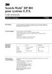
Gathering of the Green
2008 Winter Convention
March 12 - 15
Moline, IL
Magnetos: History, Application and Servicing
Splitdorf
Fairbanks Morse
Wico
Edison Splitdorf
Duane Larson
Knoxville, TN
1
Introduction
• Magnetos require periodic servicing and
repair to properly perform their function
– Provide an adequate spark at the proper time
to the spark plug
• Several knowledgeable people have led
this workshop in the past
– Covered mainly Wico C and X series
• I have researched and rebuilt magnetos
for over 25 years
– Expand workshop to cover magnetos which
came on Deere tractors from the factory
2
Acknowledgements and References
• Several folks have provided me information
– Mark Maikshilo – Mark’s Magneto Service
– Steve Ridenour and Jack Kreeger – Y and 62
– John Nikodym – early D magnetos
• References
–
–
–
–
Magneto manuals
Deere parts books and SM-2029 Electrical Manual
Field Service Bulletins
Public libraries – Flint, MI and Indianapolis, IN
• Handout available – Application Chart plus other
information
Handouts from the Gathering of the Green
workshops are among the information included
on the CD available through this web site.
3
EXTRA Slides
• Magneto talk was long, several slides not
used for time consideration
• Noted by EXTRA in Title box at top of slide
• Included here because often contain
useful information
– However, in the presentation summary slides
were sometimes used
– May affect flow of information, if confusing just
skip slides with EXTRA in title
4
Outline of Talk
• Magneto theory and operation
• Edge gap and point setting
• Engine and magneto timing
– Impulse and running
• Specific magnetos used by Deere
–
–
–
–
Splitdorf
Fairbanks Morse
Edison-Splitdorf
Wico
• Repair suggestions included for each magneto
5
Outline of Talk
EXTRA
• Magneto theory
– How a spark is produced
• Magneto operation and timing
– Getting a spark at the correct time
• Impulse and running
• Apply these principles to magnetos found on
Deere tractors from the factory
–
–
–
–
Splitdorf Dixie, Aero, 246C, 246T – Waterloo Boy, D
Fairbanks Morse DRV2A, B – A, B
Edison Splitdorf CD, (RM) – A, D, G, (L, LA)
Wico AP, C, X – A, B, D, G, H, L, LA
• History and Servicing information
6
Magneto Theory
• Magneto – converts mechanical energy
into electrical energy
– Magnetos DO NOT use batteries
• Wico XB distributor looks like a magneto
• Faraday’s Law – any relative motion
between magnet and wire induces current
flow in wire
• Magneto Classification
– “Low tension” provide spark for ignitors
– “High tension” provide spark for spark plugs
7
Magneto Theory cont’d
• High Tension magneto classification
– Shuttle wound – stationary magnet, rotating coil
• Fairbanks Morse R2 on GP series
– Rotating inductor – stationary magnet and coil, rotating
“flux reverser” armature
• Splitdorf Dixie, Aero
– Rotating magnet – stationary coil
• Fairbanks Morse DRV2A,B, all Edison Splitdorf, Wico
• Common after AlNiCo magnet became available
• Base or Flange mount
– All Deere tractors use flange mount, except
• Waterloo Boy
• D 30401 – 130700
• All GP series (including C)
8
Magneto Theory cont’d
• Magnets
– Prior to 1917 magnet steels were used, most
commonly alloyed with tungsten or chromium
– Cobalt steel was introduced in 1917, with
improved retentivity
– Cobalt chromium steel came in 1921
• Typical horseshoe magnet on magnetos
– In 1935 aluminum-nickel-cobalt (AlNiCo) steel
was introduced
• Huge improvement in magnetic retentivity
• Allowed practical use of rotating magnet magneto
• Still used today
9
Magneto Operation
N
S
10
Purpose of the Condenser
• Purpose is twofold
– Reduce sparking at points
• As points open, condenser absorbs energy from
collapsing magnetic field, lessens sparking
– Increase rate of collapse of magnetic field
• As condenser discharges back through coil primary, it
increases high voltage available from coil secondary
• Choice of condenser
– Based on choice of coil and cam properties
during magneto design
• Coil, cam, and condenser choices are a
significant engineering design issue
11
Magneto Operation – Overview
A
EXTRA
B
C
D
E
F
12
Magneto Operation – A EXTRA
• Magnetic lines of force flow out of left end
(N pole) of magnet, through coil, back to
right end (S pole)
13
Magneto Operation – B
EXTRA
• Less of rotor covered by core, so magnetic
field through coil also decreases
• Changing flux causes current to flow in coil
primary – points closed
14
Magneto Operation – C
EXTRA
• Prior to points opening, primary current in coil
resists flux decrease
• When points open, effect is gone, resulting in
extremely rapid change in flux
• Here, primary current has reached maximum
value and points are opening (edge gap)
15
Magneto Operation – C cont’d
EXTRA
• Primary resistance increases from 0.5 ohms
to infinite as points open
– Current drops to zero
– Voltage spikes
– Arc at points as they open
• Condenser absorbs arc energy, reduces arc
16
Magneto Operation – D
EXTRA
• Points open, arc stops
– Flux reverse through coil complete
– Condenser discharges back into coil primary
• Aids flux reversal
• Flux reversal induces high voltage in coil
secondary
• Edge gap
– Points open
– Maximum HV
17
Magneto Operation – E
EXTRA
• Secondary voltage overcomes plug gap
resistance – get spark
– Current flow across plug gap, resistance
decreases, secondary continues to discharge
– Flux change inhibited, extends time of spark
18
Magneto Operation
• Magnetic rotor has moved 180°, flux
reestablished in opposite direction
• Cycle repeats to produce two sparks per
rotor revolution
S
N
19
Magneto Operation - Summary
• There is a critical position during rotation
of the magnetic rotor
– Magnetic field collapsing and reversing in coil
– Maximum current is flowing in the primary,
and opening the points at that point in the
rotation produces the “best” spark
• Critical rotor position is the distance
between the edge of the magnet and the
trailing pole face and is called the Edge
Gap
20
Edge Gap Distance in Wico X Magneto
0.095” wire gives correct Edge Gap
21
Edge Gap
• Edge gap distance
– Distance between magnet
edge and trailing pole face
– Determined during magneto
design
• The cam, which opens the
points, is part of the
magnetic rotor shaft
• Set points to open when
rotor position is at edge gap
EDGE GAP
DISTANCE
– Ensures hottest spark
possible
• Setting the point gap
approximates the edge gap
22
Setting Point Gap vs Setting Edge Gap EXTRA
• What does “Setting the Points” mean?
– Rotate magnetic rotor (and cam) until point rubbing
block is on highest part of cam
– Adjust stationary point to proper gap
• Rotate magnetic rotor back until points JUST
start to open
– The trailing edge of the rotor should be at the edge
gap distance from the pole face
• So, setting the points approximates setting the
edge gap
– Not as accurate due to cam wear, worn bushings, or
worn rubbing block
23
Point Gap and Edge Gap Distances
• Splitdorf Dixie, Aero, 246C,T
– Point gap 0.020”, edge gap 0.020”
• Fairbanks Morse DRV2A,B
– Point gap 0.012”, edge gap 0.203”
• Edison Splitdorf
– CD
– RM
Point gap 0.015”, edge gap 0.042”
Point gap 0.015”, edge gap <0.125”
• Wico AP, C, X
– Point gap 0.015”, edge gap 0.095”
24
Magneto and Tractor Start and Run Timing
• Basics
– Drive cup slot in end of governor shaft
• Drives magneto
• Rotates in same direction and rate as flywheel
• Horizontal when piston at TDC (1937 SAE Standard)
– Magneto impulse spark occurs
– “LH Impulse” flywheel mark
• Lines up with mark at 3:00 on transmission housing
– One piston is at TDC
• 30° below transmission mark – piston 30° BTDC
– Flywheel side plug fires, 180° later pulley side
25
Magneto and Tractor Start and Run Timing
• First discuss running timing
– Example
• John Deere A
• Wico C or X magneto
• Choose 30° BTDC for spark to occur
– Magneto produces spark when magnetic rotor
is at Edge Gap distance
• Fixes position of magnetic rotor
– Key element is the magneto drive cup
• Connects the magnetic rotor to drive slot
26
Magneto Timing – Wico C or X
• Driven Flange Group
– Fixed to rotor by mated flat on shaft
• Drive cup
– Edge held against driven flange by
impulse spring inside cup
– Drive cup free to turn on rotor shaft
• Running timing is determined by
drive cup
– Cup shown is 25° drive cup
• Blue edge is for 30°, orange for 35°
• Wear points
– Driven flange on rotor shaft
– Drive cup on driven flange
27
Magneto and Tractor Start and Run Timing
• Back to example – want spark with pistons at
30° BTDC
– Flywheel is 30° BTDC
– Drive slot at 30° BTDC
– Magneto has 30° drive cup
• When rotor at edge gap distance magneto drive cup
fits into slot
– Sparks occur at 30° BTDC with tractor running
• How do we get the starting timing at TDC with
30° drive cup?
28
Timing Considerations
EXTRA
• Determine when engine requires spark
– Starting – at Top Dead Center (TDC)
– Running – choose 30° BTDC for our example
• Distillate burners - 35°, gasoline burners - 25°
• Determine when magneto produces spark
• Couple magneto to tractor to get spark at
right time
– Accommodate both starting and running timing
• For example, choose simple case
– John Deere A
– Wico C (or X) magneto
29
Engine Timing – Spark on Compression Stroke EXTRA
• Flywheel (left, #1) side spark plug fires first, followed
180° later by pulley (right, #2) side spark plug
• Want starting spark on flywheel side, at TDC
– Remove spark plugs, put thumb over hole, rotate flywheel
slowly until air pushes on thumb (compression stroke)
– Continue to rotate until LH Impulse line on flywheel lines up
with mark on transmission case
• Late A, punch mark on flywheel hub lines with V on cover
– Confirm TDC
• Wire in spark plug hole
• Remove crankcase cover, visual inspection
– When all is correct, magneto drive flange will be horizontal
• S.A.E. Standard, adopted January 1937, revised 1941
30
Magneto Timing – Wico C or X
EXTRA
• Magneto produces spark when
magnetic rotor is at edge gap
distance
– Fixes position of magnetic rotor
• Driven Flange Group is positioned
on rotor by machined flat on shaft
• Drive cup lip is held against driven
flange by impulse spring inside cup
– Drive cup is free to turn on rotor shaft
• Running timing is determined by
relative position of cup and flange
– Cup shown is for 25° drive cup
• Blue edge is for 30°, orange for 35°
31
Running Timing
EXTRA
• Running timing is determined by the choice
of drive cup
– Only variable in the whole system
•
•
•
•
•
•
•
3744
4702
3565
2061B
7596
6274
2040
35 deg
35 deg
35 deg
30 deg
25 deg
25 deg
20 deg
long lug
long lug
short lug
short lug
long lug
short lug
short lug
¼” lugs
hard to find
gear driven
32
Running Timing
EXTRA
• The governor drive cup slot and flywheel rotate in
the same direction at same rate
• When the flywheel (and crank and pistons) is 30°
before TDC
– The magneto drive slot is 30° BTDC
• 8:00 – 2:00 position
– The 30° drive cup on the magneto is also in the 8:002:00 position when the rotor is at the edge gap distance
– A spark is produced and the engine fires at 30° BTDC
• But how do we get the starting timing to be at
TDC with a 30° drive cup?
33
Impulse Unit Aids in Starting
EXTRA
• Achieves two goals
– Provides mechanism to delay spark
– Increases spark intensity for easier starting
• Operation
– Magnetic rotor shaft rotates slowly during starting process
• Pawls on driven flange group rotate out, catch stop
• When pawl strikes stop, magnetic rotor stops but drive cup
continues to rotate and winds up impulse spring about 70°
• When the drive cup lugs are nearing horizontal, an edge of the drive
cup strikes the pawl and pushes it off the stop
– Energy stored in impulse spring is released, the rotor snaps
forward, rapidly passes through the edge gap, and stops
against the drive cup
• As the rotor passes the edge gap distance the points open and a
spark is produced at TDC
• Difference between running and impulse timing is the
“lag angle”
34
Impulse Unit Aids in Starting
• Achieves two goals
– Provides mechanism to delay spark
– Increases spark intensity for easier starting
• Operation
– Magnetic rotor shaft rotates slowly
– Pawl on driven flange rotates out, catches stop
• Magnetic rotor stops
• Drive cup continues to rotate
– Winds up impulse spring about 70°
• As drive cup lugs approach horizontal, edge of drive cup
strikes pawl, pushes it off stop
35
Impulse Unit Operation
Pawl striking trip arm, spring windup starting
36
Impulse Unit Operation
Drive cup pushing pawl off impulse stop
37
Impulse Unit Aids in Starting
• Operation cont’d
– Energy stored in impulse spring is released
• Rotor snaps forward
– Rapidly passes through the edge gap, stops against the
drive cup
• As rotor passes the edge gap distance, points
open and spark is produced at TDC
– Rotor speed ~800 rpm
– Pawls drop out at ~220 rpm
• Difference between running and impulse
timing is the “lag angle”
38
Impulse and Running Timing
• Wico has an adjustable impulse stop
– Other brands used on Deere use fixed stops
– Accomodates
• Impulse timing changes when magneto is rotated
to fine tune running timing
• Accumulated wear in magneto and gears that drive
the magneto
• Running timing determined by drive cup
• Impulse timing determined by position of
impulse stop
39
Impulse Stop and Running Timing
EXTRA
• Can use impulse stop to approximate
running timing
– Assuming no wear in magneto or drive gears
• Set points at 0.015 (approximates E-gap)
• Set impulse stop at degrees of running
timing of drive cup
Handouts from the Gathering
– Use marks cast in housing
– Details in Handout
of the Green workshops are
among the information
included on the CD available
through this web site.
• Mount magneto, rotate backward until
impulse trips, lock down
40
Mounting (any) Magneto on Tractor
• Rotate flywheel so #1 piston is at TDC on
compression stroke (air rushes from plug hole)
– Magneto drive slot horizontal
• Hold magneto in a vise in the same position as on
tractor
– Connect plug wires from magneto to spark plugs –
ground spark plug case to vise
– Rotate drive cup with wrench until spark occurs at plugs
• Drive cup lugs will be ~ horizontal
– Not all magnetos provide a spark every impulse
• Rotate enough times until you know which plug fires first,
followed by spark at second plug 1/2 turn later
– Rotate until spark occurs at first plug, and stop
• Put magneto on tractor without rotating drive cup
• Install spark plugs and plug wires – first to #1,
second to #2
41
Setting Running and Starting Timing
• Measure circumference of flywheel
– About 66” for Model A
• Calculate distances for different timings
– Distance = circumference x deg adv/360
•
•
•
•
D(25°) = 66 x 25/360 = 4.583” ~ 4 19/32”
D(30°) = 66 x 30/360 = 5.500” = 5 1/2”
D(35°) = 66 x 35/360 = 6.417” ~ 6 13/32”
D(40°) = 66 x 40/360 = 7.333” ~ 7 11/32”
• Measure off and chalk these distances
CCW starting at the LH Impulse mark
42
Setting Running and Starting Timing
• Locate a timing light and battery to run it
– Hook spark sensor to #1 plug wire
• Start tractor, being careful to leave marks
• With the timing light in the plane of the
flywheel center and mark on transmission
case, see which mark lines up with case
– RPM does not matter
• Get about ±10° change by rotating magneto
– If the 35° mark lines up and you want 30° timing,
rotate magneto forward
• Forward retards spark, back advances spark
43
Setting Running and Starting Timing
• After running time is correct, set start timing
– Stop engine, remove timing light, mark position
of magneto so it can be replaced accurately
– Rotate flywheel, note where impulse occurs
relative to LH Impulse mark
• Adjust Impulse Stop Ring for spark at TDC (or 1°-3°
ATDC)
• If magneto impulses after LH Impulse has passed
mark, impulse stop ring will be rotated CW
– Remove magneto, loosen four screws holding
impulse stop ring, rotate stop ring, tighten screws
• Each cast-in mark in case near top of stop ring is 5°
– Replace magneto, lining up with mark, check
impulse time, if not correct, redo last steps
44
Setting Running and Starting Timing
• Now both running and starting timing are set to
proper values.
• If rotation of magneto does not provide desired
run timing
– Change drive cup
– Lift governor box, rotate governor drive gear 1 tooth
• Backward – spark occurs 12°-15° later (most common)
• Forward – spark occurs earlier
• If timing light shows spark jumping in time
– Loose distributor rotor
– Worn bushings
– Loose point pivot pin
45
Look at Specific Magnetos used by Deere
• Up to now information has been general, applying
(mostly) to all magnetos
• Look at specifics of magnetos
– Splitdorf Dixie, Aero, 246C, 246T – Waterloo Boy, D
– Fairbanks Morse DRV2A, B – A, B
• Fairbanks Morse R2 used on GP series – Cork Groth seminar
– Edison Splitdorf CD, (RM) – A, D, G, (L, LA)
– Wico AP, C, X – A, B, D, G, H, L, LA
• History, Application and Servicing information
46
General Servicing Information
• NEVER charge magnets with the impulse unit on
– Impulse dogs get magnetized, slow to drop out
•
•
•
•
•
Always remove magneto for governor work
Disconnect coil and condenser before testing
Always use a flange gasket
Ensure ventilation holes open in caps
If impulse unit doesn’t “snap”, broken spring
– Really messes up timing – tractor runs poorly
• Changing point gap changes timing
• 2 “points of resistance” when turning drive cup
• Get a parts book which shows exploded view of
magneto (n/a for Splitdorf magnetos)
47
Splitdorf Magnetos
• Splitdorf Company began in 1858
– Spark plugs by 1903
– Magnetos by 1908 (shuttle wound)
• Sumter Magneto Co. (Sumter, SC)
– Charles Mason patented new type magneto
• Based on Mason Principle – rotary inductor design
• “Revolutionary” – named magneto line DIXIE
• Splitdorf bought all patents, manufacturing
capabilities for $1 million in August 1915
– Sumter Division in Chicago built DIXIE magnetos
• Mostly for 1-cylinder engines prior to Splitdorf purchase
– Splitdorf developed the Model 46 (and 246)
48
Splitdorf Magnetos
• Neither Sumter or Splitdorf names appear
– Only DIXIE, inside Splitdorf Trademark
• Splitdorf AERO announced between March
and August 1920
– Change to rotor, pole faces, cam and condenser
provided all sparks with the same polarity
• All spark plugs want a negative center terminal
– Added suffix “C” to model
• Now 46C, 246C
– “Splitdorf Electrical Company” and “AERO”
replaced DIXIE on the brass cover
• “DIXIE AERO” doesn’t exist
49
Waterloo Boy Magnetos
EXTRA
• Summary in J.R. Hobbs Unstyled Deere book
• KW, Kingston, Sevison, Swiss and DIXIE on R
– Instruction Book, price list No. 3 for “R”
– Instruction Book, price list No. 5 dated 8-1-1917
• CW rotation
• Model N Instruction Manual No. 7 April 1, 1920
– DIXIE only used on N through end of production
– Models 46, 246 listed
• Same except for 4 (46) or 2 (246) terminal distributors
• Parts Catalog No. 26 (1926)
– Lists 46,246, 46C, 246C
– Assume went from 246 to 246C by late ’20 or ‘21
50
Waterloo Boy Magnetos
• Summary in J.R. Hobbs Unstyled Deere
book
• KW, Kingston, Sevison, Swiss and DIXIE
on R
– Instruction Book, price list No. 5 8-1-1917
• CW rotation
• DIXIE used until late ’20 or ’21
• Replaced by AERO
– Used until end of production
51
Splitdorf Magnetos on Model D
• CCW rotation base mount
• 30400 – 35308
AD116R
– Aero 246C magneto with Sumter Model B impulse
using a top switch to set trip
• Spec 136115
• 35309 – 81069
AD295R
– Aero 246C magneto with Splitdorf Model EM
enclosed impulse unit with side switch for trip
• Spec 136116
• 81070 – 130699
AD597R
– Aero 246T magneto with EM impulse
• Spec 136540
• 246C had brass sides and cover
• 246T had zinc alloy cast sides and cover
52
Splitdorf Aero 246C with B2 Impulse Unit
53
Splitdorf 246T Magneto with EM Impulse Unit
Splitdorf 246T with EM Impulse Unit
54
Splitdorf Service Information
• Disassembly straightforward
– Remove covers, impulse unit, magnets
– Remove condenser, coil
– Pot metal base and end plates
• Check for looseness of rotor and bearings
– Bearing cups become loose in end plates – problem
• Check coil
– Primary 0.5 ohms, secondary 7000 ohms
– Replacement coils available
• Check condenser
– 0.09 – 0.11 mfd
– Often leaky, use a modern replacement with a
working voltage >500 volts
55
Splitdorf Service Information
• Be careful to line up timing dots on pinion
and distributor gear
• Point setting 0.022”
– Make sure they fit together squarely
• Splitdorf service information
– IH Magneto Manual
56
Fairbanks Morse Magnetos
• Magneto development started in 1921
• R series introduced in 1924
– Shuttle wound armature
– R2 use began on the C at 200111
• Used on all GP series tractors until GPWT 405109
• RV series introduced ~July 1933
– First “rotating magnet” design
• Chrome steel magnets
–
–
–
–
–
Furnished to Deere, have “D” prefix
Base mount DRV2 used on GPWT 405110-end
Flange mount DRV2A used on A series
Flange mount DRV2B used on A and B series
Spark at uneven intervals –(180° - 540°)
• Click (spark) – click (spark) – click (no spark) – click (no spark)
57
Fairbanks Morse R2 “John Deere” Magneto
58
Fairbanks Morse Magnetos
• Deere unhappy with FM service - documented
– Letter to FM Dec 20, 1934 lists complaints
• FM needs to provide same high level of service obtained
from other manufacturers
– Magnetos not efficiently serviced
– Require re-servicing too quickly
– Service costs too much
– FM letter (Jan 15, 1935) to their Service Stations
• Read enclosed JD letter
• Get supply of parts
• Need to “render real service”
• Deere starts experimenting with Wico
– June 17, 1936 - first use of AP477 on B
• Last use of FM magneto by Deere Oct 1937
59
Fairbanks Morse Magnetos
EXTRA
• Impulse units on DRV2A, DRV2B
– Lag angle determined by key position in drive
member, not drive cup
• Drive cups same, drive members labeled
– Wico – drive member fixed to rotor shaft, lag angle
determined by drive cup
– Lag angle NOT adjustable as on Wico
magnetos – pawl stop is a fixed pin
– Running timing cannot be adjusted separately
from impulse timing, as can be done on Wico
60
Fairbanks Morse DRV2A Magneto
61
Fairbanks Morse Magnetos
EXTRA
• DRV2A
– A 410000 – 424024
– AR, AO 250000 – 251485
– Two different impulse units used
• YB – pressed steel drive cup, welded lugs
– Replaced at magneto s/n 136200 by
• XD – machined drive cup
• UB3 – modern replacement unit - forged drive cup
– “short lug” drive cup used
62
Fairbanks Morse DRV2B Magneto
63
Fairbanks Morse Magnetos
• DRV2B
– Model B has gas tank flange ½” closer to
governor box – not room for DRV2A
– Goal was to use same magneto on A and B,
rotated magneto body 90°, leave flange same
• Provided adequate clearance for plug wires
– Problem with B flywheel casting, used p/n
AB210R until B14038, after which AB706R
was used on both A and B
• Interesting story here!
– Long lug drive cup, 35° lag angle
– YB and XD impulse units used as for DRV2A
64
Fairbanks Morse Magnetos Service
• Deere provided a DRV2A, B Service Manual
• Remove top cover
– New gaskets available
– Check coil (correct replacements available)
• Primary 0.5 ohms, secondary 5000 ohms
• Remove end cap
– New gaskets not available
– To replace condenser, must remove points and
distributor assembly – clean both
– Check condenser, 0.19 – 0.21 mfd
• Unsolder can, remove stuffing, solder in modern capacitor
• Remove impulse unit, magnetic rotor, bearings
• Reassemble, set points 0.012”, check gear
timing
65
Fairbanks Morse Magneto Timing EXTRA
• Time magneto to tractor
– Remove spark plugs
– Rotate flywheel until #1 on compression stroke
– Not every magneto impulse generates spark
• Click (spark) – click (spark) – click (no) – click (no)
– RH (bottom) terminal provides 1st spark, then LH (top)
– Lay plug on magneto, connect to RH terminal
• Turn impulse with wrench, observing sparks
• When plug fires, stop turning, mate horizontal magneto drive
cup to horizontal slot on governor
– Attach magneto
• RH (bottom) plug wire to #1, LH (top) wire to #2
– Time magneto with timing light
66
Edison Splitdorf Magnetos
• History
– Edison company wanted to make radios
• No licenses being sold, bought Splitdorf for license
• Formed Edison-Splitdorf subsidiary of Edison Co
– October 1932
– Made spark plugs and magnetos
– Edison Splitdorf Model CD announced Jan ’36
• First use by Deere on Model D November 1936
– Followed by use on Model G in May 1937
– Model A in Fall 1937
– Edison Splitdorf Model RM announced Feb ’37
• First magneto with AlNiCo magnetic rotor
• First use on Model 62 (March – July 1937)
67
Edison Splitdorf CD Magneto
68
Edison Splitdorf CD Magneto
• Rotary Inductor design
– Stationary coil and magnet
– Rotate legs of magnetic circuit to reverse field in coil
– Carry over from AERO design
• Model AA impulse unit
– Check to hear/feel impulse “clunk”
• Disassembly – remove
– Distributor block, rotor, safety gap
• Rotor pin offset so goes on only one way
– 6 screws holding front plate, remove plate
• Leave 2 dowel pins which locate plate
• Remove primary lead wire
• Can now check coil, points, condenser
69
Edison Splitdorf CD Magneto
• Coil
– Primary 0.5 ohms, secondary 6000 ohms
– New coils are available
• Condenser
– Capacity 0.132 – 0.168 mfd
– Tecumseh 30548-B 0.172 mfd, physically fits
• Points
– Rework existing points
– Set opening to 0.015”
• Additional work requires magnet charger
– Remove rotor, clean & repack bearings, etc.
• Typical problems
– Coil insulation drips into rotor causing it to stick
– Thumb nuts holding spark plug wires missing
70
Edison Splitdorf CD Magneto
• Reassemble magneto
– Reconnect primary wire
– Install new gasket, line up dowel pins, install
cover
• Mate “L” on distributor gear with pinion gear mark
• CD Service Information available includes
– Edison Splitdorf CD Service Manual
– JD Field Service Bulletin 125
– JD Electrical Systems SM-2029
71
Edison Splitdorf RM Magneto
72
Edison Splitdorf RM Magneto
• Rotating magnet design
• AlNiCo magnet
• Model AA impulse unit, different from CD
• Types used:
– Spec 03509
• L621000 – L622580 62 and unstyled L
• 10° 6702 drive cup and 62953 gear
– Spec 03757
• L625000 – (5/39 - 2/42) styled L
• 20° 6734 drive cup and 62953 gear
• Used short magnetic rotor shaft
– Spec 03761
•
•
•
•
L (?) – L639999 styled L
LA1000 – LA4532
20° 6733 drive cup and 62961 gear
Used long magnetic rotor shaft
73
Edison Splitdorf RM Magneto
• Remove the distributor cap and rotor
– Clean rotor disk with eraser
• Remove points and condenser for inspection
and servicing
– Neither are readily available, no longer made
– Condenser has value 0.19 mfd
• Point spring attaches to condenser can
• Modify condenser for diesel pony motor
– Too much capacitance – 0.33 mfd
• Remove coil cover to check coil
– Primary 0.4 ohms, secondary 5000 ohms
– New coils are available
– May have to remove coil to clean up “tar” from coil
74
Edison Splitdorf RM Magneto
•
•
•
•
Replace coil cover using new gasket
Check brushes in distributor cap
Set points to 0.015”
Time magneto to tractor
– Verify correct gear 10° thru unstyled L, 20° rest
– Move timing hole cover on bell housing
• Turn motor until “SPARK” on flywheel in hole center
– Turn rotor CW until center of copper is next to
grounding button, then turn until points open
– Rotate magneto top to the right, mesh magneto gear
with driving gear
– Rotate magneto left to keep rotor from moving, push in
place, adjust so points just opening, fasten in place 75
Wico magnetos
• Started as Witherbee Igniter Company 1897
• Developed EK magneto 1919-22
– Over 1 million sold for 1 cylinder farm engines
• 1920 changed name to Wico
• Developed good rotating magnet designs
– Implemented in models A and AP
• June 17, 1936 - first use of Wico magneto by Deere
– AP477B on B 24050
– Deere flip-flopped between AP477 & DRV2B
• Used AP477B only from B49200 - 89999
– Used on A from 478500 – 488000
76
Wico magnetos
• Wico introduced model C January 1939
– Used immediately on Deere H (Jan 1939)
• Nebraska test on H1000, Oct ’38, used E-S RM
– Then exclusively on the
•
•
•
•
•
•
B at 90000 (~Feb 1940)
A at 488000 (~July 1940)
L at 640000 (7/17/41)
LA at 4533 (~July 1941)
G at 11981 (10-1-41)
Tried on D at 152708 (1942)
– But the D continued mostly with the E-S CD-0010
– The C was used until introduction of the X
77
Wico magnetos
• Wico introduced the model X Aug 1946
– Available as X(H)orizontal and X(V)ertical
– Featured better magnetic rotor design
• AlNiCo replaced the Nipermag rotor
• Improved bearing design
• Replaced the model C on the
– A at 598519 (~Dec 1947) to 659289 (XB)
– B at 217799 (~Dec 1947) to 268819 (XB)
– G at 29248 (~Jan 1948) to 46500 (D-R)
• And the E-S CD spec 0010 on the D at
187103 (~Oct 1949) to end
78
Wico AP Magneto
79
Wico AP Service Information
• Well built magneto – rotor spins on needle
bearings (available)
• Coils available, not points and condensers
– NOS points around, rebuild condenser
• Condenser value 0.16 – 0.20 mfd
• Impulse drive cup spring not available
– 5/16” wide, C & X springs ¼” wide
• Overhaul instructions in SM-2029
– FSB 126
80
Wico C Magneto
81
Wico C Service Information
• Replacement for AP series
– Needle bearings to bushings
– Cheaper
• AP – Aug 1939 list price $37.20
• C – March 1941 list price $24.50
• FSB 131 (March 1942) – C furnished as AP replacement
• Points, condenser, coil, most parts available
• Model C issues
– Early versions had Zimac castings
• Stalk holding magnetic rotor came loose
– Damaged rotor and pole faces, point opening varies
• Wico improved design, noted by “3” cast in frame
• Always ensure magnetos have the 3 cast in!
– Later versions had aluminum castings
82
Wico C Service Information
• Remove distributor cap, make sure rotor
button is not loose on magnetic rotor shaft
– If loose, replace it
– Try to wiggle end of rotor shaft
• Problems if it moves
– Loose stalk – replace case
– Worn bushings – replace
– Allows timing to vary as point opening varies in time
– Rotate shaft to open/close points
• Check if movable point loose on pivot pin
• Remove points and condenser
– Be careful to note locations of point spacers
83
Wico C Service Information
• Check condenser
– 0.16 – 0.20 mfd, no leakage
– Replace if bad
• Check points, clean and hone smooth
– Check rubbing block – if worn replace
• Check coil
– Primary 0.42 ohms, secondary 5000 ohms
– If secondary open, replace
84
Impulse Servicing for C and X
• Inspect impulse end for wear
– Check where drive cup edge meets driven flange – if
worn increases running timing
•
•
•
•
Remove drive cup nut, and drive cup
Pry out impulse spring, clean, re-grease
Remove spacers, washers, spring retainer
Inspect where driven flange/rotor shaft meet
– Should not be able to rotate flange on shaft
• May be stuck so tap to see if loosens on shaft
– Often worn, also increases running timing
• If magneto shaft worn, replace shaft (expensive)
• If driven flange worn, replace
• Replace parts in order, keep last spacer
85
Replace Impulse Spring in Wico C, X Units
86
Impulse Servicing for C and X
• Replace spring in impulse cup
– Picture shows procedure
– Using pliers to wind can damage spring
• Replace spacer on shaft, place cup over
shaft, line up inner spring loop in both
spacer holes
• Carefully lift cup, rotate CCW 1 full turn
• Replace nut and tighten
• Smaller spacer washers available, allows
additional windup for hotter starting spark
87
Wico C Service Information
88
Wico C Service Information
• Install cover, condenser, points
– If new, check carefully where the point spring
attaches to the condenser bracket
• Common for edge of spring bracket to touch
condenser bracket – grounds out points
• Problem worse with aftermarket kits
– Set points via edge gap distance
• Install rotor button and cap
89
Wico C Service Information
EXTRA
• Check point opening – should be ~0.015”
– If “close”, leave as is, as points set for max spark
– If not, something else wrong, have checked
• Install condenser and coil wires under point
spring screw
• Install rotor, distributor cap
• Check for spark
– Do final timing when on tractor
• Service information for C, X in SM-2029
– FSB 127 (C), FSB 159 (X)
90
Wico X Magneto
91
Wico X Service Information
• Replacement for Wico C (and E-S CD)
• Better magneto
– AlNiCo magnetic rotor – hotter spark
– Bearing on outboard end of magnetic rotor
• No stalk to come loose
• Common troubles
– Rotor button comes loose
• Can replace just spring
– Coil clamps crack and break, get into
magnetic rotor
– Bearing goes bad (rust, dirt, …), sticks
92
Wico X Service Information
• Remove cover, check rotor button
• Remove condenser, points
– Check condenser, value depends on coil used
• X5700C (stamped), capacitance 0.30 – 0.34 mfd
– Or “hot” coil
• Taped coil, 0.16 – 0.20 mfd
• Remove coil clamps, check for cracking
– If cracked, replace
• Check coil resistance
– Primary 0.50 ohms, secondary 7500 ohms
93
Wico X Service Information
• Check ease of rotation
– If rotates freely, except for two points of
resistance per revolution, bearing ok
– If not, must disassemble impulse unit
completely, replace bearing (6201)
• Install points
– Set points via edge gap distance
• Install rotor button, cover
94
Set Edge Gap on Wico X Magneto
95
Wico X Service Information
EXTRA
• Check point opening – should be ~0.015”
– If “close”, leave as is, as points set for max
spark
– If not, something else wrong, have checked
• Install rotor, cover
• Check for spark
– Do final timing when on tractor
96
Summary
•
•
•
•
•
•
•
•
Discussed OEM magnetos for all Deeres
Seen improvements in magnetos
How to time magneto to tractor
Importance of correct drive cup
Advantage of adjustable impulse on Wicos
Highlights of service for magnetos
Handouts contain application details
Service information available
Handouts from the Gathering of the Green
workshops are among the information included
on the CD available through this web site.
97