1
'$I;-~fS:L~
.
-'!w""'t"
'~,~"r):;ty;
'.-
..
Manhattan House
Bridge Road
Maidenhead
Berkshire SL6 8DB
Telephone:
Maidenhead
(0628) 75851
Telex:
847898 MANSKY
Facsimile:
(0628) 782812
•
ST425 WINCHESTER DISC DRIVE
SERVICE MANUAL
June 28, 1984
Manhatt.n ~
Bridge Road
Maidenhead
Berkshire SL6 808
-
J
•
Seagate. 920 Disc Drive. Scotts Valley, CA95066 • (408) 438-6550
•
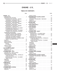
TABLE OF CONTENTS
SECTION
PAGE
l.e INTRODUCTION •• ..............
1.1 Specification
·.
~
.
Summary ••••••••••••••••••••••••••
1.1.1 Physical
2
Specifications •••••••••••••••••• 2
1.1.2 Reliability
Specifications ••••••••••••••• 3
1.1.3 Performance
Specifications ••••••••••••••• 4
1.1.4 Functional
Specifications •••••••••••••••• 4
2.e THEORY OF OPERATIONS •••••••••••••••••••••••••••••••
2.1 General
Description • .............
Interface
2.1.1 Recording
2.1.2 Track
•
•1
Format ••
For ma
2.1.3 Read/Write
t ...
5
• •5-6
·
. •7
7
0 •••••••••••••••••••••••••
Heads •.•••••••••••••••••••••••
iBe s ••••••••••..•••••••••••••••••••••••••
2 •1 •4 D
2.1.5 Air Filtration
2.2 Mechanical
8
8
System ••••••••••••••••••••
8
Theory •.••••••••••••••.•••••••••••••
9
0 Sensor .....•.•...•..........•••..
9
2.2.2 Index Sensor ••...•..•..••••.....•..•.....
9
2.2.1 Track
2.2.3 Ground
2.3 Electrical
Spring •••••
Theory ••••••••••••••••••••••
2.3.1 Main Control
PC Board 2e321-eel •
2.3.2 Microprocessor
2.3.3 Drive
·
.• • • 9
•le-18
.... le
Operation ••••••••••••• 11-12
Select ••••••••••••••••••••••••••••
2.3.4 Read Operation ••••
2.3.5 Write Operation •••
I
·
·
13
. •14-15
. •16-17
2.3.6 Fault Detection •••••••••••••••••
.....
18
2.4 Test Point Data - PC Board 20321-001 •••••.• 19-21
3.0 FIELD SERVICE
3.1 Removals
AND ADJUSTMENTS
and Adjustments ••••••••••••••••••••••
3.1.1 Main Control
3.1.2
...... ........••••• 22
• ....... .........•25-32
- Index •••••••••
2.5 Schematics
PCB ••••••••••.•.•••••••••••
Index Sensor •••
3.1.3 Ground
Spring ••
·
·
3.1.5 Front Cover LED •••
3.1.6 Frame ...•.••••••
4.0 ILLUSTRATED
.• 27
4.1 Interface
4.2 Exploded
4.3 Component
•28
•• 29
- INDEX.
Connectors •• .....................
View •••.••••
·
• 27
.....................• 27
.....................•28
o Sensor •••
PARTS CATALOG
26
. .26
3.1.4 Front Cover •••••• ......................
3.1.7 Track
26
••• 30
. •••
31
Locations •••••••••••••• .......... •••32
4.4 Parts List - PC Board 20321-001 •••••••••••• 33-34
5.0 FIELD SALES OFFICES •.•••••••••••••••••••••••••••••
35
J
II
ILLUSTRATIONS
FIGURE
PAGE
1.0 Test Point Layout - PC Board
20321-001 •••••••••••• 20
2.0 Test Point Timing - PC Board 20321-001 •••••••••••• 21
3.0 Interface
4.~ Exploded
5.0 Component
Connectors ••••••••••••••••••••••••••••••
View ......•..............•..•.•........•.
Locations
30
31
PC Board 20321-001 •••••••••••• 34
III
1.8 INTRODUCTION
The ST425
is Seagate's
25.52 Megabyte,
Winchester
disc drive.
The ST425
has
capacity of 20.0 Megabytes.
a
5 1/4 inch
formatted
The ST425 is the newest addition to the ST400 family of
disc drives, and has the same interface, power supply
and controller
requirements
as the industry standard
Seagate ST406/412/419 series.
Minislider
heads and an advanced
stepper motor design
enable higher track density. The new head design allows
increased
bit packing which utilizes
more of the disc
surface. High reliability
is assured through the use of
Seagate's proven metal band-actuator, stepper motor head
positioner
and a direct-drive
brushless
DC spindle
motor.
The spindle
motor
assembly
is aynamically
balanced
and the Head Disc Assembly
(HDA) is shockmounted to reduce vibration.
The low mass/load force of the MiniWinchester
heads and
the lubricated
oxide coated
media provide
reliable
start/stop
operation.
Each disc surface is read by two
read/write heads. The HDA, which includes the read/write
heads, discs and band-actuator
assembly, is completely
sealed
and
protected
by a captured-air-space
recirculation
system employing
a 0.3 micron absolute
filter. A filtered
port permits ambient
air pressure
equalization.
Thermal
stabilization
delays are unnecessary
with the
ST425. The spindle pump assures adequate air flow and
uniform
temperature
distribution
throughout
the HDA.
This allows significantly
greater off-track margin and
immediate read/write ability after power-up.
Only DC voltages
(+5 and +12 V DC) are required. All
electronics
are packaged a single printed circuit board.
The board is mounted
outside
the sealed
media area
allowing
easy field
access
without
risking
media
integrity. Simplification
of mechanical
and electrical
design provides
a projected
service
life of more than
11,000 hours Mean Time Between Failures (MTBF).
1
1.1 SPECIFICATION
1.1.1 Physical
Environmental
•
SUMMARY
Specifications
Limits
Ambient Temperature Limits
Operating:
5~o to 1130F
-4eo to 14~oF
Non-Operating:
(l~O to 450C)
(-4eo to 6eoC)
Maximum Temperature Gradient
Operating:
18oF/hour (l~oC/hour)
Non-Operating:
Below Condensation
Relative
Maximum
Humidity:
8 to 8e% non-condensing
Wet Bulb:
78.8oF
Maximum Elevation
Operating:
Non-Operating:
(260C)
-l,~ee feet to le,e~e feet
-l,~~~ feet to 3~,~~0 feet
Maximum
Shock Without Incurring Physical Damage
[11 msec shock pulse, half sine wave]
Operating:
3 GiS
Longitudinal:
5 GiS
Lateral:
7 GiS
Vertical:
35 GiS
Non-Operating:
will
occur within
the
No mechanical
damage
specified limits.
Maximum Vibration
Operating:
Frequency
2--22 Hz
22-5ee Hz
5~e--22 Hz
22---2 Hz
Without
Maximum Vibration Without
Non-operating:
Frequency
2--22 Hz
22-5~~ Hz
5~~--22 Hz
22--2
Hz
DC Power Requirements
+12 Volts +5%
+5 Volts
±5
Maximum Ripple:
Incurring
•
above
Soft Errors:
.~10" double amplitude
~.25 G (peak)
0.25
G (peak)
.01~" double amplitude
Incurring
Physical
Damage.
.~4~" double amplitude
l.~
G (peak)
G (peak)
.e40" double amplitude
1.0
1.6 A Typ., 3.5 A (at power-on)
1.1 A Typ., 1.7 A (Max.)
5e mV peak to peak (12 V, 5 V)
2
Heat Dissipation
Typical:
Maximum:
25 Watts
29 Watts
Mechanical Dimensions
Height:
Width:
Depth:
Weight:
Shipping Weight:
3.26
5.75
8.00
4.6
7.0
1.1.2 Reliability
MTBF:
MTTR:
PM:
The component
Specifications
design
Read error Rates
inches Maximum
inches
inches
pounds [2.1 Kg]
pounds [3.2 Kg]
@250C Typ. usagt
11,000 POH
30 minutes
Not required
life is 5 years.
(Based on bit-jitter
Soft Read Errors
Hard Read Errors
Seek Errors:
*:
** :
reduction)
1 per 1010 bits read
1 per 1012 bits read
1 per 106 seeks
Bit-jitter reduction determines the relationship between
the leading edge of read data and the center of the data
window. The data separator must provide at least -40 dB
of bit-jitter
reduction
at 2F with an offset error of
1.5 nsec shift from the center of the data window.
:*Recoverable within 16 retries
Not recoverable within 16 retries
~/
\
3
1.1.3 Performance
Specifications
CAPACITY
FORMATTED
Per Drive:
Per Surface:
Per Track:
20.0 MB
5.0 MB
8,192 Bytes
Access
UNFORMATTED
25.52 MB
6.38 MB
10,416 Bytes
Time:
Seek Times Including
Single Track:
Buffered Seek
Average Seek:
Full Seek:
Settling
19.67 msec
(from last Step pulse to SEEK COMPLETE)
65 msec
140 msec
Transfer Rate:
Average Latency:
1.1.4 Functional
5.0 MBits/sec
8.33 msec
Specifications
Rotational Speed:
Recording Density:
Flux Density:
Track Density:
Cylinders:
Tracks:
Read/Write Heads:
Discs:
3,600 RPM ±l%
10,568 Bits per inch (Maximum)
10,568 Flux changes per inch (Maximum)
550 Tracks per inch
306
2,448
8
2
4
2.0
THEORY OF OPERATIONS
2.1 General
The ST425
Interface.
Interface
Description
Winchester
supports
the
Seagate
ST506/412
The interface consists of a 34 pin control connector, a
20 pin read/write
connector
and a 4 pin DC connector.
The 34 pin connector provides 10 control signals to the
drive and returns 5 status signals to the controller.
The 20 pin connector
handles
the Modified
Frequency
Modulation
(MFM) data to/from the drive and supplies the
drive-selected
status to the controller.
The 4 pin
connector provides +5 and +12 Volts DC.
In general,
the control
connector
is "daisy-chain"
terminated
throughout
the user system,
while
the
read/write
connector
is terminated
radially.
The
following
tables
indicate
the
ST425
interface
requir'ements.
5
..
32
28
24
SELECT
34-DIRECTION
PIN
2
DESCRIPTION
18-HEAD
10*
8*
30
26-DRIVE
-STEP
SELECT
1
23-HEAD SELECT 22
22*
IN 2
20*
16
SELECT
RESERVED
SIGNAL
6-WRITE
GATE
14
-DRIVE
4
12*
-READY
20
-INDEX
-TRACK
"
-HEAD
Jl/Pl
- CONNECTOR
-SEEK
~lRITE
COMPLETE
FAULT
RESERVED
(ToPIN
~2 ASSIGNMENTS
Pin 7)
PINGROUND RTN.
*Status
enabled with DRIVE SELECT or Radial Option
J2/P2
GROUND RTN.
- CONNECTOR
PIN ASSIGNMENTS
5 9NOT
11
PIN
7
3
RESERVED
19
15
+MFH
-HFH
+MFr-l
-fvlFH
GROUND
CONNEC£ED
HRITE
Write
READ
DATA
DATA
Data
1-DRIVE
SIGNAL
DESCRIPTION
SELECTED
(To
J1 Pin 16)
PIN
J3/P3 - CONNECTOR
PIN
PIN
PIN
PIN
1
2
3
4
PIN ASSIGNMENTS
+ 12 VOLTS
+ 12 VOLTS RETURN
+ 5 VOLTS RETURN
+ 5 VOLTS
6
2.1.1 Recording
Format
The ST425 uses Modified Frequency Modulation
(MFM) as
the encoding method to record data. This double-density
encoding
scheme increases
disc capacity
by replacing
clock bits with data bits. Clock bits are written only
when data bits are not present in both the preceding and
current
bit cell.
Clock
bits
are written
at the
beginning
of the bit cell, while data bits are written
in the midd Ie.
Due to predictable
bit-shift
phenomena,
the ST425
requires pre-compensation
of write data on cylinders 128
through
305. This function
must be provided
by the
controller
to ensure data integrity
at the specified
error rate. The data pattern determines which bits must
be pre-compensated.
The recommended
amount
of precompensation is 12 nsec for both early and late written
bits. All other data patterns are written on time.
2.1.2 Track
I
P
Format
The ST425 uses a slightly
modified version of the IBN
System-34 double-density
format. This format is common
to many industry standard floppy-disc drives.
When formatted,
each sector is identified
by a unique
identification
field,
containing
cylinder,
head and
sector
information,
address mark and error checking
polynomials.
The Seagate format uses Cyclic Redundancy
Checking
(CRC) for error correction.
This format also
allows
for
a plus
or minus
speed
variation
of
aproximately
3%. The specification
for spindle
speed
variation
is 1% over the specified
environmental
and
power limits.
7
2.1.3 Read/Write
Heads
When operational,
the
read/write
heads fly on an air
bearing
created
by the rotating
disc.
There
is no
dedicated landing zone. The head and flexure (supporting
arm) are designed for contact start/stop operation •
..
The Winchester heads are loaded toward the disc surface
at 9.5 ~l grams. This is a typical
value to allow the
required
stability
in all operating
conditions.
A
typical flying height measured at an inner radius is 15
±2 microinches.
At an outer radius the height is 25 ~3
microinches.
The head/flexure
assembly
incorporates
a
design that is resistive to head and/or media
low mass
damage.
2.1.4 Discs
The ST425 employs two non-removable
double-sided
5 1/4
inch discs. These discs are designed using current iron
oxide
technology.
Disc
dimensions
are 40mm inside
diameter by l30mm,outside diameter. The thickness of the
magnetic
coating
is 20 microinches
at the ID and
increases linearly to 40 microinches at the ODe
The disc surface is coated with a flourocarbon lubricant
25 to 55 Angstroms
in thickness.
The lubricant
has
sufficient abrasion resistance to withstand a minimum of
10,000 start/stop cycles.
2.1.5 Air Filtration
System
The
ST425
incorporates
a captured-air-space
air
filtration system. The 0.3 micron filter maintains Class
100 standards within the sealed Head Disc Assembly (HDA)
and requires
no maintenance
during
the life of the
drive.
A filtered
port
allows
ambient
pressure
equalization.
During
normal
operation
there
is no
measurable
air flow between
the HDA and the outside
environment.
2.2 Mechanical
2.2.1 Track
Theory
0 Sensor
The Track 0 optical
interrupter
provides
an output
whenever
the Winchester
heads
are positioned
over
Cylinder Zero. This signal is used by the internal drive
control electronics during the power-on/auto-recalibrate
routine. The Track 0 signal is also output to the drive
interface
for use by the controller.
Note that the
signal at the interface is really Track 0/Phase
A. The
8
I-
/-
..:.
2.2 Mechanical
2.2.1 Track
Theory
~ Sensor
The Track 0 optical
interrupter
provides
an output
whenever
the Winchester
heads
are positioned
over
Cylinder Zero. This signal is used by the internal drive
control electronics during the power-on/auto-recalibrate
routine. The Track 0 signal is also output to the drive
interface
for use by the controller.
Note that the
signal at the interface is really Track 0/Phase
A. The
Track 0 optical interrupter incorporates an infrared LED
and an infrared
sensitive
photo-transistor.
When the
heads are positioned
at Track 0, an interrupter
arm
attached
to the stepper motor shaft breaks the light
beam between
the two components
of the sensor.
The
sensor will output a valid Track 0 signal as long as the
beam remains broken.
2.2.2 Index Sensor
Once each revolution the Index Sensor provides an index
pulse to the microprocessor
for recalibration. The ST425
Index Sensor is of the reluctance
transducer
type. The
sensor incorprates a built-in preamplifier.
The case of
the sensor is grounded, which ties the drive DC returns
to the drive casting.
The hub of the spindle
motor
has two metal
tabs
attached. One is ferrous and the other, which is mounted
1800 is non-magnetic.
Each revolution
of the spindle
motor causes the ferrous tab to rotate past the sensor,
thereby inducing a pulse.
Note: Please do not attempt to set the Index Sensor gap
without
referring
to the appropriate
section
in the
field service section of this manual.
2.2.3 Ground
Spring
The ST425 incorporates a grounding contact between
spindle motor hub and the PC Board ground plane.
9
the
TEGRATOR
2.3 Electrical
2.3.1
Motor
-"
SPINDLE
VOLTAGE
- Main Control" PC Board 20321-001
Speed Control
Block Diagram
-
Theory
MOTOR
SPEED
DYNAMIC
SENSOR
LSIBRAKE
\lCSB)
HALL
CURRENT LIMITER
MOTOR
DRIVERS
MOTOR
SPINDLE MOTOR CONTROL
Refer to schematic on page 23.
The sequence of normal operations. is as follows:
Hall Effect Transducer
Located inside the spindle hub, This magnetic transducer
senses spindle position and provides
dynamic feedback
proportional
to the speed of the motor. Two complete
square waves are generated each motor revolution.
This
positional
information is supplied to the spindle motor
control LSI (IC 5B,pin 3). To prevent both phases of the
motor from being selected
simultaneously,
the motor
control LSI inverts the Hall input to coil A.
Spindle Motor Control LSI
When current is applied, the spindle motor control
sets the motor speed to 3,600 RPM nominal.
This
integrates
and transforms
the error messages
from
Hall
effect
transducer.
Using this information,
outputs the correct
current flow each revolution
corrects the motor phase driver at output pins 6 and
LSI
LSI
the
it
and
7.
When power is interrupted, the Motor Control LSI shorts
both phases of the motor to ground, allowing
the motor
generated back-EMF to bring the spindle to a stop.
10
2.3.2 Microprocessor Operation
Block Diagram - ..
CONTROLLER
CONTROLLER
STEP DIRECTION
HEAD SELECT 0, 1,2
SEEK COMPLETE
READY
TRACK 0
CONTROLLER
DRIVE
SELECT
INDEX
CIRCUIT
WRITE CIRCUIT
MICROPROCESSOR
\6500/
IWR
MOTOR VOLTAGE
TRACK 0
CIRCUIT
SPINDLE
MOTOR
Functional Description The ST425 uses a microprocessor to monitor and control
internal drive functions and host interface lines. The
MPU has only three active modes: Initializing, Seeking
or Waiting.
At power-on, the MPU initializes the stepper circuit to
phase A and resets all interface
lines under its
control. Power is then applied to the Spindle Motor
Control LSI and the index line is monitored for spindle
rotation. If rotation is not sensed within 15 seconds,
the MPU assumes a problem and removes power.
As the drive spins-up, 66~ revolutions
are counted
before the MPU assumes that the drive is "at speed," and
initiates recalibration. If the heads are not over Track
~, the drive will step at 3 msec per track. When both
mechanical Track ~ and electrical phase A are present,
the drive is at true Track ~ and stepping will cease.
Within 2~ msec both SEEK COMPLETE, TRACK ~ and READY
will go true, and the drive is then ready to accept
inputs from the controller.
When in the idle mode, the MPU loops, waiting for step
pulses. The MPU also monitors its RESET line (pin 39)
for a low to high signal,from IC 4F, which causes the
MPU to reinitialize (see above).
11
~;f:~j'~-~~~"··'-"·'·~'·-·'~""">~·-····~~h""
Upon receiving a Step pulse, the MPU pauses for 599
usec, to allow for additional pulses, before executing
the seek operation. Every incoming pulse resets the 599
usec timer. The seek operation will not begin until the
last pulse is received.
When seeking, the MPU evaluates the number of track~ to
be covered and searches the PROM for the most efficient
path. Seeks longer than seven tracks involve a complex
acceleration/deceleration
routine to optimize
the
motor
and carriage
characteristics.
Steps
are
accomplished by setting IC 2B to sequential phases. It
provides both a current source and sink with the motor
winding. Near the end of a seek, 2D and 2E are set to
provide
additional
current
to offset
expected
hysteresis.
Upon completion of a seek operation, settling time is
calculated
based upon the length of seek, and the
interface line is activated
in the specified time
period. With SEEK COMPLETE, the MPU returns to the idle
mode.
Whenever a seek ~peration crosses the write current
switch boundary at Track 126, the microprocessor reduces
the write current to the heads during write operations.
:'
,
;
.
12
.;.'
I~
2.3.3 Drive
Selection
Block Diagram
ACTIVITY LED
STEP
DIRECTION
PULSES
LINE
RECEIVER
INTERNAL
DRIVE
SELECT 42
ELECT
1
TO INTERFACE
-
READY
DRIVE SELECTED
SEEK COMPLETE
INDEX
WRITE FAULT
TRACK\!
LINE DRIVER
Functional Desciiption
DRIVE SELECT serves only tb gate other signals to or
from the drive
interface.
Without
DRIVE SELECT,
the
drive cannot Read, Write or Seek.
13
~"J.[lT~~WJiIIf,;.~1I:~~.,"i!J_'liJt.~~t'~liI4f~~t>;:f"""'.i:""';"""';,'
".".:'."'-" ••:.,"
,'<
,"
"
Jit'..
.,
•
,
:: •••. :
:.
' .••
.-
".·····!{;th~~;\ill;~)i.,·".,t~iJi.s;i·
..'.'
' ..,,,
,.",.".",.,':i ..~._.~:,;,,,,,.,,
,· ~,,,."•.~..:·,." ,." .,
;.'..
2.3.4 Read Operation
Block Diagram
- .
HEAD SELECT
tlnlerfacel
READIWRITE
HEADS
LSI
PREAMP
LOW PASS
FILTER
READ DAiA CONVERSION
READ/WRITE
LSI tiC 6HI
MFM READ DATA
(Inlerfacel
,
Functional
Description
-
Head Select
The binary decoder,
IC 2F, selects
the desired
head
based on the status of the 3 head select lines. If the
DC voltages are too low (possibly causing an inaccurate
write operation),
pin 12 will
force the decoder
to
choose a nonexistent
head. During read operations
the
head center tap is set at approximately
5 Volts by the
e to
Read/Write
LSI, IC 6H, pin 27. By referencing
+5 Volts,
actual
ground appears
as -5 Volts,which
eliminates
the necessity
of a negative
power source
normally required by the LSI preamp, IC 4G.
LSI Preamp
With the head center tap active, data from the selected
head will flow into the preamp. This preamp amplifies
the read signal and also acts as a high pass filter.
Low Pass Filter
This filter network
attenuates
high frequency
which is outside the normal data signal range.
14
~.;~'.'.~~~'
.... ,.~',
noise,
Read Data Conversion
Amplified data enters
the Read/Write LSI (IC 6H) at
pins 1 and 2 and exits as high speed MFM (differential)
read data at pins 17 and 18. The Read/write
LSI
functions are:
1. Read data shifted 900'
2. Analog to digital conversion
3. Erroneous data bits removed
4. Conversion of digital data to MFM (differential) data
providing
immunity to common mode noise during
transmission
.)
L·
15
~..~
...•.
,.,.. "
----------------~~~~.
~•• ".~-_"_- ••_"' •• - -. __ •••
u
_
2.3.5 Write Operation
Block Diagram
~,;'..' .:",t . ~
FROM INTERFACE
lSIREADIWRITE
(IC6Hj
MFM
HEADS
READIWRITE
WRITE DATA
GATE
DIFFERENTIAL
SELECT
WRITE DATA PROCESSING
WRITE
HEAD
Functional
DescriptionI~
In order
true:
to WRITE,
the
1. Write
Fault
inactive
2. Drive
Select
active
3. Drive
Ready active
4. Seek Complete
5. Write
following
conditions
must
be
active
Gate active
Write Gate
A write
sequence
is initiated
when Write
Gate
is
activated
which causes the Read/Write
LSI (IC 6H, pin
26) to apply +12 Volts to the selected
head's center
tap. At the same time, data is sent to the Read/Write
LSI, pins 15 and 16.
16
-.-.' .. -:--:.;::(:;:-:-":"""''''·'''~\':'~':''\'':~~~~~~.)!f4Iii'-~'n_,IiJLlfllI!lUllU.aJIJUll.I.IIIJJLJI.JII..•
;
:
.'
"'-~;-.'-',
.
L~'&~
Write Data Processing
Differential write data, which is precompensated
MFM, is
received from the host controller
by the Read/Write LSI
and changed to single line pulse data. Depending whether
plus or minus data is to be written, the Read/Write LSI
activates
either pin 7 or 8 of the pre-amp LSI (IC 4G).
The amount of current to be written
is established
by
the Read/Write
LSI. When writing to the inner heads (2
and 3), write current is reduced to lessen the problems
of pulse crowding.
'!, ~~
-,'
17
..:-::
.
2.3.6 Fault Detection
~lock Diagram - :~.'
I
.
'
..
COMPLETE
SEEKtlnlerface
READY
.'
..
,
DC POWER
tinier/ace
HEAD
SELECT
tiC 6HJ COMPARATOR
Iinierfacel
OMPARATOR
I
t
.
•
tinier/ace
WRITE
I FAULT
MICROPROCESSOR
RESET
'"_J.
..
READ/WRITE
I
LSI
. ..
Functional Description •
Any combination'of the following events will cause a
Write Fault condition and will prevent the drive from
writing:
1. Multiple heads selected
2. DC voltages greater than 29% low
3. Seek Complete
active
or Ready inactive
when Write Gate is
Voltage and Bead Comparator Select
The Read/Write LSI (IC 6H) constantly monitors both the
+5 and +12 Volt lines to detect a low-voltage condition.
If +5 Volts is >15% low or +12 Volts is >20% low, the
DC-unsafe signal is activated (IC 6H,pin 25) causing
write current to be disabled, the microprocessor reset,
the fault line activated (IC 6H, pin 24) and the heads
deselected.
If multiple heads are selected the Read/Write LSI will
disable the write circuitry and send a write fault to
the interface (IC 6H, pin 24)•
. "'-.
18
...
...··)::·~:~if~A'~/i··:
:.j·~ti~{j~¥~fdi:~::·:
..
:.-;"
2.4 Test Points
~
2.4.1 Test Point Data
Test Points
PC Board 2e321-eel
1 and 2 (Differential
Read Filter):
Test Points 1 and 2 may be used to observe
the
Differential Read Data. The typical amplitude of the
signal resulting from adding the two channels is l6e
mVolts. The signal is observed at Cylinder Zero, head
e or 1.
A full track record of high frequency data (eeee or
1111) should resemble the diagram in Figure 2.e.
Test Point
4 (Track 9 Sensor):
Test Point 4 may be used to monitor the Track e Sensor.
A high logic level indicates valid Track e. The Track e
signal is valid for Cylinders 1 and 2.
Test Point
5 (Index Sensor):
Test Po int 5 may be u·~edto monitor the Index Sensor. A
high logic level is a valid Index indication. Only the
leading edge of the pulse may be considered valid. The
typical signal at TP 5 should resemble the diagram in
Figure 2.e.
Test Points
11, 12, 13, 14 and 15 are ground.
,
.:;:\:):~
19
FIGURE 1.9
TEST POINT LAYOUT
PC BOARD 29321-991
. ..
®
CD CD
®
@i
CD
®
®.
.TEST POINT
DESCRIPTION
1&2
Differential Read Filter
Track 8 Sensor
Index Sensor
Ground
4
5
11,12,13,14,15.
29
.... - .
.-::'::'
,.;;:,.,...~W""".;,
..".•..•
4+,••"""-"~~f'~')~.'~Jfil1I~l]
i. ··.··~;tl~~\~;iiil1~!jf:.
,
.
::.
.
,","."
,
..
1.tJJ~[~d'IIHRlltWil
FIGURE
2.8
TEST POINT TIMING
DIFFERENTIAL
PC BOARD 28321-881
READ FILTER
f
160mVoits
Typ.
TEST POINTS
\-
200 no••
-\
INDEX SENSOR
mTPOINTS
n_
Jl.''.
16.67 msec
±1%
=jL
1.3 msec
21
Typ.
1&2
-
2.5 ST425 SCHEMATICS
INDEX
. ..
SECTION
2.5.1
PAGE
Main
Control
PC Board
2~32l-~~1
•••••••••••• 23-24
22
.. 'i"
"<:;"'-
•
(6
7
'«.->'
4
5
(
3
2
3G
D
+sv
n
l.L
~
22
I
.
:9C.3~1
~
eo
'6
c51O¥
O~
~\~~~~.\
17
1e-2,1" 22 •."
to••..•
IT
18
19
J5
10
- -
Z70fF ~ '3~.
39
+5V
1134
~
,.
'1211
(
R38
1>111:.
1>.73
51
,
l~
..,.
'0
'7
RI2
IV\,
Slo
R40
·2
2.w
+WRI'TE
..:17
t)A.TA
-=-
_E!
•
-WRIT<
1»0.1"
CRI
•• 12'1
~
R\7
33"
"
-=-
:!IF
-'¥IRI'T!
c:. •.
Co
T<
Ii!.'
+RQ.Oy
-+SEEk.
i'5
- DC UN!>••FE
COMP
+ WR.\"fE.
.om
~
~9
:!>~(
+R/WR
~
5E
~+12V"
1>2K
~9
O~J
f
~
I
100
"'2,390'"
'V'-R2.4
CI9
;-~WE
W
"fYPE
I='AUI..'
~
EN' !icE
35
SEl.EC.T
-ACTIVITY
~
747
14,5
~
14
LEO
L.M
~
.SV
DtoOE AR
ZIlKI~.
+5'
t \2v/\
"-'>0
""'
J..I
-
..
11 •••... ~
A
\0
~t
~+,,:;rI"'TY
LEO
.51
'E !oM"
"'''II
+5"
~3K
5E
••
R2?
IIUIT
131r..\%
C:OWOlUl
TO ~
•••
c. .,...,
"........
--
..-""""
5E
..
DATI.
I
JI
11IO
1.»&uI.!.:2
.....
~
•
C\
1"~5111 W
7
....
....
6
5
4
D
2
I
\
•
(
6
7
5
~, .sv
J
••
2
--
~.~-:-:
~v
.m tR
., ~
I R50
.;;~.
o
to
~-
9
) II<.
J-
-tw-""
~
1~~h"2
I
~~v
-to",.
20~
f)j~
._ :
'tOlUC.T\QH
IN
3F
7
~
~ ,i~'
~
t#fr
.sF
A'\3 "t5~
I:
,It
=2
~'.
~
f
i
~
I
ZN
-t}\.~7~~
A1I
.---
RA9
IZ
I
~I~
oe
0\ QI
P2QZ
~~~~
RIob
~V"'¥f.
-oc.u~
~.5V
-t~F,tW.T
:!LCZS .1. C2B
"1""100 T
'"
-IIZV
I
I
Q
"1,~
Q<j15
- 03 Q3
Q!>
~~
If
CZlo
c!>z
A
P
~
.3 CAPACITANC.E
~
!5 ---\i'-iNOICATE5
CDNN£C.T~"J2·
'" !t,NOICATE5
Tf:5T
-*
7F
V'A\..u[5
IN MIC.",oFAl<A~.8<>
°
------------------
t~j;~
.."--IS"
...;8"'-..:)(10'________________________________
-=2"'Z'-~"-1
..-
~Io8
I
1-
.••••
RE
·20'-.
-s..E'-():>o\~
-R,£"'OY
'0)(
-"TfVoO,<;Irtti
12. X
- WR,I'Tt.
'F~T
,"-•...
(.)Ft"
INDICATES CONN£C-roIt. ~
~IO-
~~"
POINT PIN5·
I
II I
J,
I-
-
0_ L-. -~~~.
~=
:~;' ~~~E",r_vr"';.<;;."''':''~
2~X
......
LMIIII~..•..
;;;;:;;0
D
I
~
:ma;;
VI
~
+R./wR.
=....1I(f -M",,"Oll.OH
-----------.
7
NCTr~
"'ID
CR.'
_
~
:!>K
•
I
u;;-
GNP
1'1.15.'1
N01'~:
UNLE.SS C7Tt1t;!tWYSE
sPECIFIEO.
I· RESI5TANCf: VAl.\JFS AI.( IN
OHM5.l<qw.:>%
2. A"L "A, RESlsTo~ •••••.• Va w·
4
u
REF. t.f.S--iAST-U'S
'C271C~1'"!I"'\I2..".
47 Jc~.~41
'-~
W'
X OOOP'ltJ~I·~
~~1(..CiJ.:~~i2.1
fr
---j--- -.___
wD
~
Q;
Q
:~1
5>1
~
I
QI P.
I~~
D3
C.Z9
~•
:~."
I
I
.
I
.IZ,"••• I
c&
10 ••••
~
~~
4""
.314
-@
~
,"r,..r
w
--
"T?9
S~.",
~
~
"'"
~
~
J.'.
~:
~
~
.-
:!\",'0_J
~
,.
Rio'
VV~
""~
~5fi7 PC:>
1-,
i,
5
-
~~
':i
-
\-"':.J
<1~ZK
t-
.
.".
"1'1>1
'/\"---\5V
G!>JO
B
;
:r~'
1
• ~
1 ••••
~
~
...f01
•..
'RI>IO'
TA.ISTA'TEt..Ilt.
1001(..
.!:IF
.q KY
R44' ~R45
t:...1~ '" ~IO
~
I
5
__ u_.
-j.
.
1
4C.
" ~.~.•C
{
I
"""
I 'f\A;:'Z
I
.:5V
wJl
.•. :,..
,~
rf:7
IRP7a
1..3
~
I
-J.!
I I
I
(.
"""'"
11r"V'\l'_
I
••
I
I
~I<~'
ry!>
+i5"
I II
•
6
5
4
,
2
~~~
~f'QfI."-"T
~
.2032\:-'00\
1
3.9 FIELD SERVICE AND ADJUSTMENTS
SEAGATE disc drives do not require preventative
maintenance. All units shipped are covered by a one year
factory warranty. Should field service or adjustment
become necessary, certain restrictions apply. Primarily,
the sealed Head Disc Assembly (HDA) must not be opened.
Seagate considers a drive to be out of warranty if the
the HDA has been tampered with. Any special tools or
additional
cautions
will
be treated
under
the
appropriate sections.
This section of the ST425 Service
Manual
covers
adjustments and procedures concerning field-accessible
components. Any questions not treated in this document
should be referred to your regional Seagate Technical
Support office. Field Support offices, and their phone
numbers, are listed at the back of this handbook.
Should it become necessary to return a drive to Seagate,
please ensure that the drive is shipped in the original
container. If that is not possible, your Technical
Support office wiJI assist you in.obtaining an approved
container.
Please Note: Shipping a drive in an unapproved container
could cause damage and will void your warranty!
: 1
..,:~'
.,,'
;
:',t
-, .....
-
~_0
I' ,
,
",
'-,
,,'
~
I
25
N
:j
~+f~1II!1I1III.
11',...
r-r "
!
~'~~~'>¢I'"
'",
','.
"
----<--
~{;:-~'~~:~:cr"~I",;':,;~;~'~'
,'.
.!
3.1 Removals and Adjustments
Note: Removal of any assembly not covered in this
section is not possible without special tools and cleanroom facilities.
BEFORE PERFORMING ANY OPERATION LISTED BELOW, PLEASE
PROVIDE A CUSHIONED WORK SURFACE.
3.1.1 PC Board
Tools Required: T-10 Torx Driver
1. Place the drive on a padded surface, PC Board up and
with the front cover to your left.'
2. Remove the front cover by removing (4) mounting
screws.
3. Disconnect the Front panel LED by removing the twowire connector.
4. Disconnect P6, P7 and PB, located at the left edge of
the PC Board, noting their position.
5. Disconnect the Printed Cricuit Cable, J5, located at
the upper edge of the PC Board (12:00 o'clock).
6. Disconnect the spindle motor cable, P4, located on
the lower edge of the PC Board. (6:00 o'clock).
7. Slide the PC Board out to the right.
Note: It is recommmended that the replacement PC Board
be powered-up with the head cable, P5, disconnected.
This will ensure that a damaged replacement does not
alter data on the disc. To determine if the Board is
good, the Write Fault signal can be monitored at the
junction of the inverter and Rl13. If a high logic level
exists at junction Rl13, then a No-Write-Fault condition
exists and the PCB can be powered down and P5 connected.
Avoid creasing the Printed Circuit Cable when removing
P5. Inspect the cable after this operation.
3.1.2 Index Sensor
Tools Required: T-10 Torx Driver,
Loctite #242, .030" shim
Note: This procedure
data.
may result in a loss of recorded
1. Remove the PC Board (see above).
2. The Index Sensor is mounted to the casting directly
to the left of the spindle motor and may be removed
by first freeing the LED connector from the front
cover (noting its orientation) and then remove the
Index Sensor clamp.
26
,',
.'
.~
3. To
reinstall,
apply
Loctite
to the first three
threads
of the
mounting
screw.
Replace
the
Sensor, clamp and screw, but do not tighten.
Rotate the spindle motor until the silver index tab
aligns with the Index Sensor.
Using the .030" shim, adjust
the gap between
the
Index Sensor and the index tab.
Tighten the mounting clamp screw and verify that
the gap is .030 inch.
Route the Index Sensor wires through the retaining
clip and reconnect the LED connector.
Replace the PC Board.
5.
6.
7.
8.
4.
3.1.3 Ground
Tools
Spring
Required:
T-10 Torx Driver
Loctite #242
1. Remove PC Board (see above).
2. With the front cover to your left, the Ground Spring
is at "12:00 o'clock" to the spindle motor and may be
removed using the T-10 Torx Driver.
3. When reinstalling,
apply
Loctite
to the first 3
threads of the mounting screw.
4. Verify that the Ground Spring contact button and the
spindle
motor ball are clean and making positive
contact.
3.1.4 Front Cover
Tools
1.
2.
3.
4.
Required:
Remove the
Remove the
Disconnect
Remove the
T10 Torx Driver
.
PC Board (see above).
four front cover mounting
the LED connector, noting
cover.
screws.
its orientation.
3.1.5 Front Cover LED
Tools
Required:
T-10 Torx Driver
Note: A water base hot-melt
the LED/grommet assembly.
glue
may be used
to secure
1. Remove the PC Board (see above).
2. Remove the connector from the Front Cover LED, noting
the orientation of the connector.
3. Remove
the LED and grommet
from the Front Cover,
noting the orientation of the LED •
..<;)
27
-
'
-
..
,
-
.
,
3.1.6 Frame
Tools
Required:T-10
Torx Driver
1. Orient the drive PC Board up and front cover to your
left •
2. Remove the PC Board (see above) •
3. Remove the Front Cover (see above).
4. Free the ground strap jumper (located on your right)
from the frame.
5. Remove the three shock mounting screws and lift the
frame up, leaving the Head Disc Assembly (HDA) on the
padded surface. If it is necessary
to transport
the
HDA, please keep it strapped down to the drive pallet
to avoid excessive shocks.
3.1.7 Track
Tools
8 Sensor
Required:
T-10 Torx Driver
Proper
positioning
adjusting set screw
be tampered with.
of the Sensor
is essential.
is set at the factory and should
1.
2.
3.
4.
The
not
Remove the Front Cover (see above).
Disconnect P8.
Position the drive on edge with the stepper motor up.
Remove the Track 0 Sensor mounting screw, using the
T-10 Torx driver.
5. Remove Sensor.
6. When reinstall ing, apply Loctite to the first three
threads of the mounting screw.
28
. ..
\ ,
@'/'
.
,
4."
ILLUSTRATED
PARTS CATALOG
INDEX
SECTION
4.1 Interface
r
PAGE
Connectors ••••••••••••••••••••••••••••
30
4.2 Explode~ View .•••••.••••••.•....•..•••••••.••..•.
31
4.3 Component
32
Locations •••••••••••••••••••••••••••••
4.4 Parts List •••••••••••••••.•••.•.••••••••••
·•••33-34
29
.•..
~.~
,
"
4.1
FIGURE 3.1
INTERFACE CONNEC'l'ORS
J3
30
/"
~
~~!"f.;::;"
(
SCREW. '6-32
x
rI
1I
1/4
NYLOX TORX DR.
~
~'
SCREW •• 6-32 x 1/4
FLAT HD. TORX DR.
d
SCREW.
x 3/8 DR.
PAN.
HD.'6-32
SLT TORX
FRAGILV'
LABEL~~
I,
~
~
,
I
0-I
CLAMP. DISC
WASHER.
SNUBBING
i
PANEL MOU~
SPACER. V.I.---OGROMMET.~;
ISOLATOR,
VIBRATION
-::
;::
c·
••
-'-;-:.
~
,~
;;~~~::~~~{
::)~-:~:~,
. ,"
·'.t
,/'
SEAL. TOP COVER
:r
w~
'11
~
",
, '-/
SCREW 16-32
,
':.
-l
i
:,-
./
SCREW. '2-56
x
1/8
SCREW •• 6-32
~BUT.
I..wASHER.
HD._ TOR X DR.
SPRING. PRELOAD,i
PCC
.,
V
~':
SCREW •• 6-32
"
;t"
:~,_
ASSY. FILTER
BUT. HD. TORX
x
'I
~
&
iV!
•
C
~CREW
BRACKET
CARRIAGE
•• 6-32 x 1/81..
BUT. HD TORX DR '-
x
THERMAL
1
'~ONT
ROD,
RETAINER.!
3/16
e':
.
,
• DISC
v-1'IN.
TENSIONER
I
6SSY,
CARRIAGE
'(~
SPACER
.
SCREW•• 6-32 x 3/16
~
I
~
I
.
i
BUT. HD. TORX DR. --......",
V
TAG.
ASSY.SERIAL~)
GRD. STRAP~I
CLIP. CORD----9
I
/1'~
I
~
CLIP. PCC
WASHER. FLAT PT.'2-56 x 1/
CARRIA,GE SCREW. OVAL
SCREW
.• 4-40
3/16 DR.
PAN.
HD.
SLT. xTORX
WELDMENT. FRAME
~
RETAINER. REAR ROD
Q,~- I
I~~'
-0,
"'0--
. DISC
,/
1......
BREATHER ~
.
IJ'
~
?
1/4
I .•••.
~
•
FLAT.6
(FLATPLATE.
HD. TORX DR. " ~ CRASH STOP. CARRIAGE
I'
1/41
,
~
;~REW. '2·56
<I§i1"
I
o
'!;
x
·BUT. HD. TORX DR
Gf--.. WASHER
.
--
~:
.t
7/8
nm,
~J~j.
~
x
x 1/8
~PAN.SCREW.
HD.'6-32
SLT. TORX
J
'
ql ~
CLIP. IND~ , ....-y"\
'"
I
SCREW. '6-32 x 3/16
l
~g~Et-+.II I
I ~~~Yi
.....•..
I "
BUT. HD. TORX DR.
SCREW. '6-32 x 5/16
BUT. HD, TORX DR.
~
'",,-, I,
MOTOR. BRUSHLESS D.C.
PAN. HD. SLT. TORX DR.
WASHER.
16
SCREW
•• 6-32
VEXTERNAL
I
~
3/16
I
\~Y'
GASKET. SPINDLE
x
GROUND SPRING
~
BAR. FIXED
E;<..Pw:>DE.t> VI'S...
W
~
~
RELEAIED FOR AIIEM.LY
IHEET
A~~D
ICALE
OF
HJtT NO.
I
IC LRYIL
(
(
.c:.
/J3JMOUNTED ON FAR SIDE
•
w
..
~
_~~
~.
ID
'~j
~
ti;
~•
~j
-IF!
•
.jj:1
w
••
••••
2.61
T""
•••@
RL
.Ro
••••••••••••••••••••
.J9
h_
•
~<::••••••
r-.>
I
~6
R/I
r. -.
~.J II ~6
:GE}.lO
LI
.•
--..r-=-l_J5
~:~.
~.
~
R62.
•
•
_F
: ••••
",,4~6.5
E.~
•••••••••••••
rk 4D
~.
:~;
Rd
R25
R26
·
••
,
• •••••••••
-~f'
.
;;"
.,'
.
R52
I
•
I.
•
, •••••
-.
• •
@
TP3
••
~~
5F'
•••••••••••••••
~
~-e
~
·k
-!~
I~
R·
•
~
11
I
~
•
•••••••••••••••
1----1111
II t;s
•
• • ••••••••••
l~. • 0 .,e
,L Ie
•••••••••••••••••
..•~:•••...
<:(6
I
7F
•
l
l
I
t
....
• •••
-..:.
8d
.~
.~i:-
r
56
•.
•
.:-.
_f
~~~
C.<l1
R39
P,40
'2"
~ ~
70
o2:
tn
I
1.••
.-~.
-1
.,
:.
•
I ••
..
I.
.:JmJ ..• ~----,
'T_~
~~ c2S
j-ll
.-1 CeO F- .-{£l2j.
•
I•
I
•
. 13: •
I •
.-QD-o'I •
MOUNTED
MOUNTED ON FAR SIDE~
.-
1-1
,
•
~
RQ4 ••
~ _~~o'-e
~~
> lID
~
••
r· • •6C.
• • • • I P• • • •7i• • •• I·
•~R7~~.
:
I:I:I~
~O
~
I
-::-.•
::;.,:
'
2:1-1
•
~
~.
<SO
7E
O~
@
~
t •
••••••••••••••
tI-1 C3f, f-.
~
jP/S
• .t-.-.-.-.-.-.-. '
•••
_~:~_I .:tfuJ::
~===~~===~
~
-p'4
•.. ; ~:::
t;;;\~:
I!.JL!
'-~~~~
,".- .
n
I h
6F
U••••••••
-cM!}--e
..•...
•• ~
~~
~,•
•••••••••••••
•.
••
:oo::~
_~_
•
~
I.
••
~~
e5
~
R16
R24
••••••••
.@
•
~
I
••••••••••••••
T
rA- •.•.•..••.
I
4F
t'"'
• ••••••••••
.l
••
4"
T.
-,.-.
RI7
RI5
~t;]
~:;
~~
R8
RI'
TPS
;:
m7
••
(,H
TPI~~ •••
TPI.
I
4G
,el"
•.
~f-.~.-CI1
(:1
~
R9
••••••••••
~
~
e7
'
~
R45
·kr·
• •
:
~I~
P••••••••~6·
m'
p•••••••
·J8
=D
--
01.';
--~j
··
I • •
•••••••••••••
•
:37
.!1
·ti
k
r•••••••
en
ill
. ¥:;
.~~
'1'":i
~6
-
:=§'8:,~
~
u_-=- _~ @
2..T
;1 ••
:i..
;;.·
•
•
•
RP2
I::..•.•----------.••
•••••••••
I~•
•
:~~j
1:
'ii
'<PI
~
••
4.4
PRINTED
ITEM
QUANTITY
1.
2.
3.
4.
5.
6.
7.
8.
9.
[2]
[2]
[3]
H~•
11.
12.
13.
14.
15.
16.
17.
18.
19.
2e.
21.
22.
[3]
[1]
[1]
[2]
[1]
[1]
[1]
[1]
[1]
[1]
[1]
[1]
[1]
[1]
[2]
[1]
[1]
[1]
24.
25.
[1]
[1]
[1]
[1]
26.
[1]
27 •
28 •
[1]
[1]
29.
[26]
3e.
[2]
31.
32.
33.
34.
35.
[5]
23.
36.
37.
38.
39.
4e.
41.
42.
43.
44.
45 •
46.
47.
[1]
[1]
[1]
[1]
[2]
[3]
[1]
[2]
[1]
[2]
[1]
[1]
[2]
[1]
[1]
[1]
CIRCUIT
BOARD - PART NUMBER
28321-881
DESCRIPTION
LOCATION
IC 74e6)
74LS14
7438
7445
7474
74123
74LS273
LM393
65ee/1
Diode Array
Pre-Amp
Motor Spin Control LSI
Read/Write LSI
MM2716 (2K x 8E PROM)
Stepper Motor Drive Ckt.
IC 74e8
Shunt, 7 Position
Trans. A~ray TPQ2ge7
Resistor pack,14 Pin DIP, 22e/33e
Resistor pack,14 Pin DIP,68e/1.2K
CAP,Ceramic lee pf, 5%, NPO
33e pf
27e pf
39 pf
5E,6F
6D,3F
6C,7C,7F
2D,2E,2F
5F
4F
4A,4D
1B
4C
3G
4G
5B
6H
4B
2B
6E
7E
2H,2J
Ohm 7D
Ohm 2G
47 pf
22
•e12
•e68
CAP,Ceramic
.1
uf,5%, NPO
uf,le% X7R
uf,le%,X7R
uf +8e-2e%
CAP,Electro1ytic,
22 uf,16V
CAP,TANT, 4.7 uf, 35V, 1e%
CAP,Ceramic
.e1 uf
CAP,Ceramic
.33 uf, 5eV, Z5U
Crystal, 2MHz, ±1%
Diode, IN4ee5
Inductor, 2.2 uh
Inductor, Ie uh
Inductor, 3.3 uh
Transistor, 2N3ge6
Transistor, 2N3ge4
Transistor, TIP12e
Resistor Pack, Ie Pin SIP,1/4W,56e Ohm
Resistor Pack, Ie Pin SIP,1/4W,82 Ohm
Resistor pack,8 Pin SIP,1/2W,82e Ohm
•I
Resistor
Pack,8
Pin SIP,1/2W
18e Ohm
68
Ohm
33e Ohm
C5
C6
C12
C13
C14
C17
C16
C18
C4,7,8,15,19,21-23
28-41,43-46
C2e ,'25
C9,11,24,26
C1
C47
Y1
CR1
Ll,2
L3,4,6
L5
Q2,3
Q1,4
Q5,6
RP1
RP2
RP5,le
RP6
RP7
RP8
33
......
.;...•..•,.•.,. ,..
48.
..
.
3~~
R6
R21
R65
14
R64
19.1
R27
R24
R59
Rl~
R12
51~
R16
R58
R28
R29
R35
R44
R57
R33
R52
33~
51
1~
3
2
15~
10~
12
39
47~
8.2
Ohm
1~~
3.3
2.4
68~
5.1
R15
R66
1.37
162
R36
R43
R18
47
4.7
1
6.2
22~
Ohm
KOhm
4.32
R7~Ohm
2.8~
K Ohm
Ohm Ohm
R9
•2R39,4~
Ohm
R5
RP9
R2,4
~5%,
Ohm
R47,49
R7,8
[4]
R37,38
R41,67,68,69
R42,46,61
R55,62,63
[3]
[9]
RI4,32,71
Rll,48
RI3,17,18,2~,22,
22K K
R23,26
[1]
[6]
R5~,53-56,6~
Resistor
[2]
Pin,SIP,IW,I~
RP3,4
1/4W,
5%.
1.2
Rl,3
54.9
1~
KOhm
1/8W,
1%, 30.1
357
Resistor,
1/2W,
2W,
5%,
33~
Pack,8
Pin
SIP,I/2W,47~
3~,31,34
34
:.11
5.8
FIELD SALES OFFICES
CORPORATE HEADQUARTERS
920 Disc Drive'
Scotts Valley, CA 95066
408/438-6550
TELEX:176455
SEAGATE
SCVL
Seagate
UD
NORTHWESTERN REGIONAL SALES
1150 North First Street, #130
San Jose, CA 95112
408/286-7580
SOUTHWEST REGIONAL SALES
5850 Canoga Avenue, Suite 400
Woodland Hills, CA 91367
213/884-2699
CENTRAL REGION SALES
9451 LBJ Freeway, Suite 220
Dallas, TX 75243
•
214/783-6711
TWX:758760
,EASTERN REGIONAL SALES
435 King Street
Littleton, MA 01460
617/486-9711
SOUTHWEST REGIONAL SALES
9700 Koger Blvd., Suite 310
St. Petersburg, FL 33702
813/577-1199
Telex:709049
EUROPEAN HEADQUARTERS
Gassnerstrasse
5
8000 Munich
West Germany
49 89 177017
TELEX:524275
35
. ,\'. ,.,•.••.".~:'_'r ~.~'.
'.