1
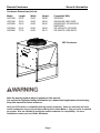
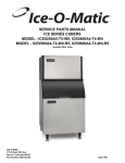
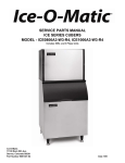
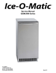
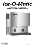
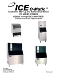
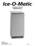
INSTALLATION AND PARTS MANUAL REMOTE CONDENSERS MODELS: VRC Ice-O-Matic 11100 East 45th Ave Denver, Colorado 80239 Part Number 9081245-01 Date 4/11 * Remote Condenser Introduction How To Use This Manual Ice-O-Matic provides this manual as an aid to the service technician in installation and maintenance of remote condensers. Do not attempt to perform installation, start-up or maintenance unless you have read and fully understand this manual. If, at any time, you encounter conditions that are not addressed in this manual, call, E-mail or write the Ice-O-Matic Service Department: Ice-O-Matic 11100 E. 45th Ave. Denver, Co. 80239 Attn: Technical Service Department E-Mail: [email protected] Telephone Numbers 800-423-3367 All Departments 888-349-4423 Technical Assistance Only (After Hours Only) Any Service communication must include: Model Number Serial Number A detailed explanation of the problem Keep this manual for future reference. Ice-O-Matic icemakers and dispensers are not approved for outdoor installation. WARNING: Always disconnect electrical power and shut off water supply whenever maintenance or repairs are performed on the ice machine and related equipment. CAUTION: Always wear protective eyewear whenever maintenance or repairs are performed on the ice machine and related equipment. Ice‐O‐Matic is devoted to sustainability in every aspect of our business. So to help offset our carbon footprint, we work with American Forests to plant a tree for every ice machine we sell. Our ultimate goal is to plant 150,000 trees over the next several years. Page i Remote Condenser Table of Contents Introduction Page i Table of Contents Page ii Freight Claim Procedure Page iii Warranty Page iv General Information Page 1 Installation Guidelines Page 2 Remote Refrigeration System Page 4 Component Description Page 5 Installation Page 6 Service Parts VRC Page 10 Page ii Remote Condenser Freight Claim Procedure Freight Claims Important! Inspect Promptly This merchandise has been carefully inspected and packed in accordance with the carrier’s packing specifications. Responsibility for safe delivery has been assumed by the carrier. If loss or damage occurs, you as the consignee must file a claim with the carrier and hold the container for carrier’s inspection. Visible Loss or Damage Any external evidence of loss or damage must be fully described and noted on your freight bill or express receipt and signed by the carrier’s agent. The claim should be filed on a form available from the carrier. Concealed Loss or Damage If loss or damage does not appear until merchandise has been unpacked, make a written request for inspection by the carrier within 15 days of the delivery date. Then file a claim on a form from the carrier. File Claim Without Delay Do Not Return Damaged Merchandise to Ice-O-Matic Page iii Remote Condenser Warranty Ice-O-Matic Parts and Labor Domestic & International Limited Warranty Mile High Equipment LLC (the “Company”) warrants Ice-O-Matic brand ice machines, ice dispensers, remote condensers, water filters, and ice storage bins to the end customer against defects in material and factory workmanship for the following: Cube ice machines,”GEM” model compressed ice machines , “MFI” model flake ice machines and remote condensers. Thirty-six (36) months parts and labor “EF” model flake ice machines and GEMD maker dispensersTwenty-four (24) months parts and labor CD model dispensers - Thirty-six (36) months parts and labor Ice storage bins -Twenty-four (24) month parts and labor IOD model dispensers - Twenty-four (24) months parts, Twelve (12) months labor Water filter systems - Twelve (12) months parts and labor (not including filter cartridges) An additional twenty-four (24) month warranty on parts (excluding labor) will be extended to all cube ice machine evaporator plates and compressors, “GEM” model compressed ice machine compressors, and “MFI” model flake ice machine compressors from the date of original installation. An additional thirty-six (36) month warranty on parts (excluding labor) will be extended to all “EF” model flake ice machine and “GEMD” maker dispenser compressors from the date of original installation. The company will replace EXW (Incoterms 2000) the Company plant or, EXW (Incoterms 2000) the Company-authorized distributor, without cost to the Customer, that part of any such machine that becomes defective. In the event that the Warranty Registration Card indicating the installation date has not been returned to Ice-O-Matic, the warranty period will begin on the date of shipment from the Company. Irrespective of the actual installation date, the product will be warranted for a maximum of seventy-two (72) months from date of shipment from the Company. ICE-model cube ice machines which are registered in the Water Filter Extended Warranty Program will receive a total of eighty-four (84) months parts and labor coverage on the evaporator plate from the date of original installation. Water filters must be installed at the time of installation and registered with the Company at that time. Water filter cartridges must be changed every six (6) months and that change reported to the Company to maintain the extended evaporator warranty. No replacement will be made for any part or assembly which (I) has been subject to an alteration or accident; (II) was used in any way which, in the Company’s opinion, adversely affects the machine’s performance; (III) is from a machine on which the serial number has been altered or removed; or, (IV) uses any replacement part not authorized by the Company. This warranty does not apply to destruction or damage caused by unauthorized service, using other than Ice-O-Matic authorized replacements, risks of transportation, damage resulting from adverse environmental or water conditions, accidents, misuse, abuse, improper drainage, interruption in the electrical or water supply, charges related to the replacement of nondefective parts or components, damage by fire, flood, or acts of God. This warranty is valid only when installation, service, and preventive maintenance are performed by a Company-authorized distributor, a Companyauthorized service agency, or a Company Regional Manager. The Company reserves the right to refuse claims made for ice machines or bins used in more than one location. This Limited Warranty does not cover ice bills, normal maintenance, after-install adjustments, and cleaning. Limitation of Warranty This warranty is valid only for products produced and shipped from the Company after March 2011. A product produced or installed before that date shall be covered by the Limited Warranty in effect at the date of its shipment. The liability of the Company for breach of this warranty shall, in any case, be limited to the cost of a new part to replace any part, which proves to be defective. The Company makes no representations or warranties of any character as to accessories or auxiliary equipment not manufactured by the Company. REPAIR OR REPLACEMENT AS PROVIDED UNDER THIS WARRANTY IS THE EXCLUSIVE REMEDY OF THE CUSTOMER. MILE HIGH EQUIPMENT SHALL NOT BE LIABLE FOR ANY INCIDENTAL OR CONSEQUENTIAL DAMAGES FOR BREACH OF ANY EXPRESS OR IMPLIED WARRANTY ON THIS PRODUCT. EXCEPT TO THE EXTENT PROHIBITED BY APPLICABLE LAW, ANY IMPLIED WARRANTY OR MERCHANTABILITY OR FITNESS FOR A PARTICULAR PURPOSE ON THIS PRODUCT IS LIMITED IN DURATION TO THE LENGTH OF THIS WARRANTY. Filing a Claim All claims for reimbursement must be received at the factory within 90 days from date of service to be eligible for credit. All claims outside this time period will be void. The model, the serial number and, if necessary, proof of installation, must be included in the claim. Claims for labor to replace defective parts must be included with the part claim to receive consideration. Payment on claims for labor will be limited to the published labor time allowance hours in effect at the time of repair. The Company may elect to require the return of components to validate a claim. Any defective part returned must be shipped to the Company or the Company-authorized distributor, transportation charges pre-paid, and properly sealed and tagged. The Company does not assume any responsibility for any expenses incurred in the field incidental to the repair of equipment covered by this warranty. The decision of the Company with respect to repair or replacement of a part shall be final. No person is authorized to give any other warranties or to assume any other liability on the Company’s behalf unless done in writing by an officer of the Company. GOVERNING LAW This Limited Warranty shall be governed by the laws of the state of Delaware, U.S.A., excluding their conflicts of law principles. The United Nations Convention on Contracts for the International Sale of Goods is hereby excluded in its entirety from application to this Limited Warranty. Mile High Equipment LLC, 11100 East 45th Avenue, Denver, Colorado 80239 (303) 371-3737 March 2011 Page iv Remote Condenser General Information Condenser Dimensions (Inches) Model VRC1001 VRC1061 VRC2061 Length 29.18 29.18 29.18 Width 29.50 29.50 29.50 Height 38.90 38.90 38.90 VRC2661 VRC5061 29.18 37.78 29.50 29.50 38.90 38.76 Compatible With: ICE0500R ICE0605/6R, EMF1106R ICE0805/6/R, ICE1005/6/7R, EMF2306R ICE1405/6/7R, ICE1506R ICE1806/7R, ICE2106/7R VRC Condenser Note the warning symbol where it appears in this manual. It is an alert for important safety information on a hazard that might cause serious injury. Keep this manual for future reference. Verify the ICE machine is compatible with the remote condenser. Some ice machines and some remote condensers may or may not have a Mixing Valve (Head Master). Only one valve is required per system. Kits are available to modify the remote condenser for compatibility. For more information contact your Ice-O-Matic Distributor. Page 1 Remote Condenser General Information Introduction Ice-O-Matic Remote Condenser Systems are comprised of three components. The pre-charged remote condenser, the pre-charged ice maker and the pre-charged line set. The pre-charged line sets are available in 25, 40, 45, 60 or 75 foot line set lengths. The 60 foot line set will require adding an additional 16 ounces of refrigerant to the system. The 75 foot line set will require adding an additional 28 ounces of refrigerant to the system. Normal installation of the ice maker should be followed. Reference the installation instructions included with the ice maker. In any installation, the pre-charged line sets, consisting of a liquid line (3/8” dia.) and a discharge line (1/2” dia.) are used as a one time initial charge type installation. Once the sealed couplings are connected and the internal seal is broken, the lines cannot be disconnected without losing the refrigerant charge. They are, however, reusable and when the couplers are removed and reconnected, the complete refrigeration system must be evacuated and re-charged with the proper amount of refrigerant. Reference the ice maker data plate or ice maker service manual for proper refrigerant charge. General Description The remote condenser should not be used in areas where sufficient airflow is not available in the area the ice maker is being installed or the heat being rejected by the condenser coil will be undesirable. The condenser coil should not be exposed to temperatures below -20°F (-29°C) or above 120°F (49°C). The remote condenser functions as a normal refrigeration system until the temperature at the condenser coil drops below 70°F. At this time the mixing valve will begin to bypass enough hot gas from the discharge line directly into the receiver to keep the liquid line feeding the expansion valve at a steady pressure. The amount of gas bypassed will depend on the temperature at the condenser coil (the colder the temperature at the condenser coil, the more gas will bypass and the tubing between the mixing valve and receiver will become warmer). For the complete explanation of this valve, refer to the schematic on page 6 of this manual. VRC Condenser Condenser Location When choosing a location for the remote condenser, reference the following guidelines: 1. Choose a location that is protected from extremes of dirt, dust, rain, sun and prevailing winds. 2. Vertical air discharge mounting of the condenser is required. 3. Condenser should be mounted higher than the ice machine. 4. Condenser must be level. 5. Condenser should not be exposed to temperatures below -20°F or above 120°F. 6. Installation must meet all local and national building, plumbing and electrical codes. Airflow Page 2 Remote Condenser General Information The VRC remote condensers incorporate the mixing valve in the condenser. This configuration allows up to a 100 foot calculated remote line set run. Reference the diagram below to calculate the maximum 100 foot line set run. Limitations for new remote machines that have the mixing valve mounted in the condenser. Maximum Rise is 35 feet. Maximum Drop is 15 feet. Maximum equivalent run is 100 feet. Formula for figuring maximum equivalent run is as follows: Rise x 1.7 + Drop x 6.6 + horizontal run = equivalent run. Examples: 35 ft. rise x 1.7 + 40 ft. horizontal = 99.5 equivalent feet line run 35 ft. rise 40 ft. horizontal Verify the ICE machine is compatible with the remote condenser. Some ice machines and some remote condensers may or may not have a Mixing Valve (Head Master). Only one valve is required per system. Kits are available to modify the remote condenser for compatibility. For more information contact your Ice-O-Matic Distributor. 34 ft. horizontal 10 ft. drop 10 ft. drop x 6.6 + 34 ft horizontal = 100 equivalent feet line run Page 3 Remote Condenser Remote Refrigeration System The Remote Refrigeration System is shown in the above diagram. During the freezing cycle, high temperature and high pressure liquid refrigerant is directed from the condenser through a mixing valve, receiver, liquid line solenoid heat exchanger and a filter drier. The expansion valve meters refrigerant to the coils on the back of the evaporator. In low ambient conditions (below 70°F air temperature at the condenser) the mixing valve opens to mix discharge gas with liquid returning from the condenser, in the receiver, to maintain discharge and liquid line pressures. The low temperature and pressure refrigerant leaving the evaporator is directed through the suction line heat exchanger and is returned to the compressor. There it is compressed to a high temperature and high pressure gas. It is then directed to a condenser to be converted again to a high pressure and high pressure liquid. During the harvest cycle, the hot gas solenoid valve (normally closed during the freeze cycle), opens and directs the high temperature gas leaving the compressor into the evaporator. Once the evaporator has reached approximately 40°F, the harvest motor overcomes the capillary attraction of the ice and the evaporator releases the ice. At the end of the harvest cycle, the hot gas solenoid valve closes and another freeze cycle begins. During the off cycle, the liquid line solenoid valve closes and the system will pump down to 10-20 psi to prevent refrigerant migration to the low side of the system. Page 4 Remote Condenser Component Description Mixing Valve (Headmaster, Low Ambient Control Valve) This valve serves as the head pressure regulating valve. It contains a pre-determined charge of nitrogen in the valve bellows. When the temperature at the condenser is above 70°F (21°C), the refrigerant flow from the compressor is directed by the mixing valve through the condenser and into the receiver. When the temperature at the condenser drops below 70°F (21°C), the pressure in the bellows of the mixing valve becomes greater than the pressure of the liquid refrigerant coming from the condenser. This change allows the valve to partially restrict the flow of refrigerant leaving the condenser and allows discharge gas to by-pass the condenser and flow directly into the receiver, mixing with the liquid refrigerant from the condenser. The amount of discharge gas that bypasses the condenser increases as the ambient temperature decreases. This action of the mixing valve allows the discharge pressure to be maintained at approximately 217 psi during low ambient conditions. If the refrigerant system is undercharged and the ambient temperature is below 70°F (21°C), the mixing valve will not work properly. The mixing valve will allow too much refrigerant to bypass the condenser. Receiver The quantity of liquid refrigerant in the receiver will vary with the temperature at the condenser coil. Liquid Line Solenoid and Pump Down Low Pressure Control When the bin is full or the ON-OFF switch is turned to the OFF position, the liquid line solenoid valve closes and the system begins to pump down. When the low pressure reaches 10-20 psi, the pump down low pressure control opens and the contactor shuts the machine off. As the ice is removed from the bin or the ON-OFF switch is turned to the ON position, the liquid line solenoid valve opens and the high side and low side pressures begin to equalize. When the low side pressure reaches 50-75 psi, the pump down low pressure control closes and the machine begins a freeze cycle. When the machine is off for extended periods of time (either a full bin or the ON-OFF switch in the OFF position), it will pump down approximately once every hour. This is due to the equalization of pressures during the off cycle resetting the pump down low pressure control. It is a normal function of the refrigeration system. Condenser Fan Motor The condenser fan motor is a single speed, permanent split capacitor motor and should be wired according to the wiring diagram. The motor is permanently lubricated for long service life. Page 5 Remote Condenser Installation Electrical Connections 1. The icemaker and the remote condenser both require a solid earth ground that meets National, State and Local Codes. 2. Reference the ice machine and condenser date plate for current requirements to determine wire size for electrical hook up. 3. Make sure the supply voltage is the same as the rated voltage shown on the nameplate. 4. Reference wiring diagram below for proper connections. INSTALLATION NOTICE: THE “VRC” SERIES REMOTE CONDENSER MAY ONLY BE USED WITH COMPATIBLE ICE-O-MATIC ICE MAKERS Electrical shock and/or injury from moving parts inside this machine can cause serious injury. Disconnect electrical supply voltage to the machine and condenser prior to performing any adjustments or repairs. Page 6 Remote Condenser Installation Support Leg Installation-VRC 1. After removal of the packaging and fasteners, lift the condenser assembly off of the skid. 2. Locate the legs and leg braces attached to the condenser assembly. Cut the wire ties and separate the legs from the condenser. 3. Locate the fasteners that are in a bag attached to the condenser top panel. 4. Assemble the legs and braces to the condenser as shown below. Page 7 Remote Condenser Installation Vertical Air Flow Page 8 Remote Condenser Installation Proper Tubing Routing When installing the discharge and liquid lines from the remote condenser to the icemaker, please use the following guidelines: 1. The remote condenser (#2) should always be installed above the icemaker (#4) as shown with a vertical air flow on page 8. 2. All excess tubing (#1) should be routed inside the building and coiled in a vertical spiral as shown (3#) on page 8, to prevent oil trapping in the lines. Any tubing run outside should be insulated to protect it from surrounding ambient conditions. Tubing should follow straight line routing whenever possible. The lowest spot in the tubing run should be the connection at the rear of the icemaker. Both the discharge line and liquid line quick connect couplers are supplied with a Schrader Valve on one end of the line set. The Schrader Valve end should be connected to the remote condenser on both the discharge and liquid line for access to pressure readings at the condenser as shown (#5) above. When attaching the quick connect couplers (#6), always lubricate the couplers with refrigerant oil. The couplers should be tightened until snug, then tightened another quarter (1/4) of a turn. Always leak check the quick connect couplers after installation has been made. Page 9 Remote Condenser Item Description Service Parts VRC1001 VRC1061 VRC2061 VRC2661 VRC5061 1 Fan Guard 9131452-01 9131452-01 9131452-01 9131452-01 9131460-01 2 Top Panel 3013222-01 3013222-01 3013222-01 3013222-01 3013303-01 3 ¼-20 x 1/2 Screw 9031019-04 9031019-04 9031019-04 9031019-04 9031019-04 4 Fan Blade 9131451-01 9131451-01 9131451-01 9131451-01 9131461-01 5 Fan Motor 9161117-02 9161117-01 9161117-01 9161117-01 9161118-01 6 ¼-20 x ¾ Cap Screw 9031001-02 9031001-02 9031001-02 9031001-02 9031001-02 7 Flat Washer 9031003-01 9031003-01 9031003-01 9031003-01 9031003-01 8 Flanged Lock Nut 9031118-02 9031118-02 9031118-02 9031118-02 9031118-02 9 ¼-20 x 1/2 Screw 9031019-04 9031019-04 9031019-04 9031019-04 9031019-04 10 Rear Panel 3013224-01 3013224-01 3013224-01 3013224-01 3013224-01 11 Brace 3013226-01 3013226-01 3013226-01 3013226-01 3013305-01 12 Leg 3013227-01 3013227-01 3013227-01 3013227-01 3013227-01 13 Leg Brace 3013228-01 3013228-01 3013228-01 3013228-01 3013306-01 14 T-Nut-Shipping Only N/A N/A N/A N/A N/A 15 Brace 3013226-01 3013226-01 3013226-01 3013226-01 3013305-01 16 Cover Panel 3013232-01 3013232-01 N/A N/A N/A 17 Center Panel 3013225-01 3013225-01 3013225-01 3013225-01 3013304-01 18 Front Panel 3013223-01 3013223-01 3013223-01 3013223-01 3013223-01 19 Motor Brace 3013234-01 3013234-01 3013234-01 3013234-01 3013307-01 20 Motor Brace Support 3013233-01 3013233-01 3013233-01 3013233-01 3013233-01 21 Junction Box Cover 3013229-01 3013229-01 3013229-01 3013229-01 3013229-01 22 Mixing Valve 9151027-07 9151027-06 9151027-07 9151027-07 9151027-07 23 Condenser 9141135-01 9141135-01 9141135-01 9141136-01 9141137-01 24 Filter 9151143-01 9151143-01 9151143-01 9151143-01 9151143-01 25 1/2 Coupling 9091001-12 9091001-12 9091001-12 9091001-12 9091001-12 26 3/8 Coupling 9091001-11 9091001-11 9091001-11 9091001-11 9091001-11 27 Filter 9151143-02 9151143-02 9151143-02 9151143-02 9151143-02 Page 10 Remote Condenser Service Parts Page 11