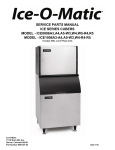
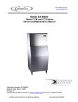
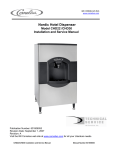
1
IMI CORNELIUS INC.
www.cornelius.com
Nordic Remote Condenser
Model: RC
Installation and Service Parts Manual
Publication Number: 631806050
Revision Date: January 1, 2008
Revision: B
Visit the IMI Cornelius web site at www.cornelius.com for all your Literature needs.
RC Installation and Service Parts Manual
Manual Number 631806050
Remote Condenser
Forward
How To Use This Manual
Cornelius provides this manual as an aid to the service technician in installation and maintenance of
remote condensers. Do not attempt to perform installation, start-up or maintenance unless you have
read and fully understand this manual.
If, at any time, you encounter conditions that are not addressed in this manual, call or E-mail the
Cornelius Service Department:
E-Mail: [email protected]
Telephone Number
800-238-3600 All Departments
Any Service communication must include:
• Model Number
• Serial Number
• A detailed explanation of the problem
Keep this manual for future reference.
Cornelius icemakers and dispensers are not approved for outdoor installation.
WARNING: Always disconnect electrical power and shut off water supply whenever maintenance
or repairs are performed on the ice machine and related equipment.
CAUTION: Always wear protective eyewear whenever maintenance or repairs are performed on
the ice machine and related equipment.
Page i
Remote Condenser
Table of Contents
Forward
Page i
Table of Contents
Page ii
Freight Claim Procedure
Page iii
General Information
Page 1
Installation Guidelines
Page 2
Remote Refrigeration System
Page 4
Component Description
Page 5
Installation
Page 6
Service Parts
Page 10
Page ii
Remote Condenser
Freight Claim Procedure
Freight Claims Important!
Inspect Promptly
This merchandise has been carefully inspected and packed in accordance with the carrier’s packing
specifications. Responsibility for safe delivery has been assumed by the carrier. If loss or damage occurs,
you as the consignee must file a claim with the carrier and hold the container for carrier’s inspection.
Visible Loss or Damage
Any external evidence of loss or damage must be fully described and noted on your freight bill or express
receipt and signed by the carrier’s agent. The claim should be filed on a form available from the carrier.
Concealed Loss or Damage
If loss or damage does not appear until merchandise has been unpacked, make a written request for
inspection by the carrier within 15 days of the delivery date. Then file a claim on a form from the carrier.
File Claim Without Delay
Do Not Return Damaged Merchandise to Cornelius.
Page iii
Remote Condenser
General Information
Condenser Dimensions (Inches)
Model
Length
Width
Height
Compatible With:
RC05001
29.18
29.50
38.90
CCM0500R
RC06002
29.18
29.50
38.90
CCM0630R
RC08002
29.18
29.50
38.90
CCM0830R
RC08002
29.18
29.50
38.90
CCM1030R
RC14002C 29.18
29.50
38.90
CCM1448R*1
RC14002C 29.18
29.50
38.90
CCM1530R*1
RC21002C 37.78
29.50
38.76
CCM1848R*1
RC21002C 37.78
29.50
38.76
CCM2148R*1
Note: *Includes 60 Hz. Single Phase, Three Phase and 50 Hz.
Note the warning symbol where it appears in this manual.
It is an alert for important safety information on a hazard that might cause serious injury.
Keep this manual for future reference.
Verify the ice machine is compatible with the remote condenser. Some ice machines and some
remote condensers may or may not have a Mixing Valve (Head Master). Only one valve is required
per system. Kits are available to modify the remote condenser for compatibility. For more
information contact your Cornelius Distributor.
Page 1
Remote Condenser
General Information
Introduction
Cornelius Remote Condenser Systems are comprised of three components. The pre-charged remote
condenser, the pre-charged ice maker and the pre-charged line set. The pre-charged line sets are available
in 25, 40, 45, 60 or 75 foot line set lengths. The 60 foot line set will require adding an additional 16 ounces
of refrigerant to the system. The 75 foot line set will require adding an additional 28 ounces of refrigerant to
the system.
Normal installation of the ice maker should be followed. Reference the installation instructions included with
the ice maker.
In any installation, the pre-charged line sets, consisting of a liquid line (3/8” dia.) and a discharge line
(1/2” dia.) are used as a one time initial charge type installation.
Once the sealed couplings are connected and the internal seal is broken, the lines cannot be disconnected
without losing the refrigerant charge. They are, however, reusable and when the couplers are removed and
reconnected, the complete refrigeration system must be evacuated and re-charged with the proper amount
of refrigerant. Reference the ice maker data plate or ice maker service manual for proper refrigerant
charge.
General Description
The remote condenser should not be used in areas where sufficient airflow is not available in the area the
ice maker is being installed or the heat being rejected by the condenser coil will be undesirable.
The condenser coil should not be exposed to temperatures below -20°F (-29°C) or above 120°F (49°C).
The remote condenser functions as a normal refrigeration system until the temperature at the condenser
coil drops below 70°F. At this time the mixing valve will begin to bypass enough hot gas from the discharge
line directly into the receiver to keep the liquid line feeding the expansion valve at a steady pressure. The
amount of gas bypassed will depend on the temperature at the condenser coil (the colder the temperature
at the condenser coil, the more gas will bypass and the tubing between the mixing valve and receiver will
become warmer). For the complete explanation of this valve, refer to the schematic on page 6 of this
manual.
VRC Condenser
Condenser Location
When choosing a location for the remote condenser,
reference the following guidelines:
1. Choose a location that is protected from extremes of
dirt, dust, rain, sun and prevailing winds.
2. Vertical air discharge mounting of the condenser is
required.
3. Condenser should be mounted higher than the ice
machine.
4. Condenser must be level.
5. Condenser should not be exposed to temperatures
below -20°F or above 120°F.
6. Installation must meet all local and national building,
plumbing and electrical codes.
Airflow
Page 2
Remote Condenser
General Information
The remote condensers incorporate the mixing valve in the condenser. This configuration allows up to a
100 foot calculated remote line set run. Reference the diagram below to calculate the maximum 100 foot
line set run.
Limitations for new remote machines that have the mixing valve mounted in the condenser.
Maximum Rise is 35 feet.
Maximum Drop is 15 feet.
Maximum equivalent run is 100 feet.
Formula for figuring maximum equivalent run is as follows:
Rise x 1.7 + Drop x 6.6 + horizontal run = equivalent run.
Examples:
35 ft. rise x 1.7 + 40 ft. horizontal = 99.5 equivalent feet line run
35 ft. rise
40 ft. horizontal
Verify the ice machine is compatible with the remote
condenser. Some ice machines and some remote condensers
may or may not have a Mixing Valve (Head Master). Only one
valve is required per system. Kits are available to modify the
remote condenser for compatibility. For more information
contact your Cornelius Distributor.
34 ft. horizontal
10 ft. drop
10 ft. drop x 6.6 + 34 ft horizontal = 100 equivalent feet line run
Page 3
Remote Condenser
Remote Refrigeration System
The Remote Refrigeration System is shown in the above diagram. During the freezing cycle, high
temperature and high pressure liquid refrigerant is directed from the condenser through a mixing valve,
receiver, liquid line solenoid heat exchanger and a filter drier. The expansion valve meters refrigerant to the
coils on the back of the evaporator.
In low ambient conditions (below 70°F air temperature at the condenser) the mixing valve opens to mix
discharge gas with liquid returning from the condenser, in the receiver, to maintain discharge and liquid line
pressures.
The low temperature and pressure refrigerant leaving the evaporator is directed through the suction line
heat exchanger and is returned to the compressor. There it is compressed to a high temperature and high
pressure gas. It is then directed to a condenser to be converted again to a high pressure and high
pressure liquid.
During the harvest cycle, the hot gas solenoid valve (normally closed during the freeze cycle), opens and
directs the high temperature gas leaving the compressor into the evaporator. Once the evaporator has
reached approximately 40°F, the harvest motor overcomes the capillary attraction of the ice and the
evaporator releases the ice. At the end of the harvest cycle, the hot gas solenoid valve closes and another
freeze cycle begins.
During the off cycle, the liquid line solenoid valve closes and the system will pump down to 10-20 psi to
prevent refrigerant migration to the roof top condenser.
Page 4
Remote Condenser
Component Description
Mixing Valve (Headmaster, Low Ambient Control Valve)
This valve serves as the head pressure regulating valve. It contains a pre-determined charge of nitrogen in
the valve bellows. When the temperature at the condenser is above 70°F (21°C), the refrigerant flow from
the compressor is directed by the mixing valve through the condenser and into the receiver. When the
temperature at the condenser drops below 70°F (21°C), the pressure in the bellows of the mixing valve
becomes greater than the pressure of the liquid refrigerant
coming from the condenser.
This change allows the valve to partially restrict the flow of
refrigerant leaving the condenser and allows discharge gas
to by-pass the condenser and flow directly into the receiver,
mixing with the liquid refrigerant from the condenser. The
amount of discharge gas that bypasses the condenser
increases as the ambient temperature decreases.
This action of the mixing valve allows the discharge
pressure to be maintained at approximately 240 psi (16.5
bar) during low ambient conditions. If the refrigerant system
is undercharged and the ambient temperature is below 70°F
(21°C), the mixing valve will not work properly. The mixing
valve will allow too much refrigerant to bypass the
condenser.
Receiver
The quantity of liquid refrigerant in the receiver will vary with the temperature at the condenser
coil.
Liquid Line Solenoid and Pump Down Low Pressure Control
When the bin is full or the ON-OFF switch is turned to the OFF position, the liquid line
solenoid valve closes and the system begins to pump down. When the low pressure
reaches 10-20 psi, the pump down low pressure control opens and the contactor shuts
the machine off.
As the ice is removed from the bin or the ON-OFF switch is turned to the ON position, the
liquid line solenoid valve opens and the high side and low side pressures begin to equalize.
When the low side pressure reaches 50-75 psi, the pump down low pressure control closes and
the machine begins a freeze cycle.
When the machine is off for extended periods of time (either a full bin or the ON-OFF switch in
the OFF position), it will pump down approximately once every hour. This is due to the
equalization of pressures during the off cycle resetting the pump down low pressure control. It is
a normal function of the refrigeration system.
Condenser Fan Motor
The condenser fan motor is a single speed, permanent split capacitor motor and should be wired
according to the wiring diagram. The motor is permanently lubricated for long service life.
Page 5
Remote Condenser
Installation
Electrical Connections
1. The icemaker and the remote condenser both require a solid earth ground that meets National,
State and Local Codes.
2. Reference the ice machine and condenser date plate for current requirements to determine wire size
for electrical hook up.
3. Make sure the supply voltage is the same as the rated voltage shown on the nameplate.
4. Reference wiring diagram below for proper connections.
INSTALLATION NOTICE:
THESE REMOTE CONDENSERS MAY ONLY BE USED WITH
COMPATIBLE CORNELIUS ICE MAKERS
Electrical shock and/or injury from moving parts inside this machine can cause serious injury.
Disconnect electrical supply voltage to the machine and condenser prior to performing any
adjustments or repairs.
Page 6
Remote Condenser
Installation
Support Leg Installation
1. After removal of the packaging and fasteners, lift the condenser assembly off of the skid.
2. Locate the legs and leg braces attached to the condenser assembly. Cut the wire ties and separate
the legs from the condenser.
3. Locate the fasteners that are in a bag attached to the condenser top panel.
4. Assemble the legs and braces to the condenser as shown below.
Page 7
Remote Condenser
Installation
Page 8
Remote Condenser
Installation
Proper Tubing Routing
When installing the discharge and liquid lines from the remote condenser to the icemaker, please use the
following guidelines:
1. The remote condenser (#2) should always be installed above the icemaker (#4) as shown with a
vertical air flow on page 10.
2. All excess tubing (#1) should be routed inside the building and coiled in a vertical spiral as shown
(3#) on page 10, to prevent oil trapping in the lines. Any tubing run outside should be insulated to
protect it from surrounding ambient conditions. Tubing should follow straight line routing whenever
possible. The lowest spot in the tubing run should be the connection at the rear of the icemaker.
Both the discharge line and liquid line quick connect couplers are supplied with a Schrader Valve on one
end of the line set. The Schrader Valve end should be connected to the remote condenser on both the
discharge and liquid line for access to pressure readings at the condenser as shown (#5) above.
When attaching the quick connect couplers (#6), always lubricate the couplers with refrigerant oil. The
couplers should be tightened until snug, then tightened another quarter (1/4) of a turn.
Always leak check the quick connect couplers after installation has been made.
Page 9
Remote Condenser
Item
Description
Service Parts
CCM0530
CCM0630
CCM0830
CCM1030
CCM1448R1
CCM1530R1
CCM1848R1
CCM2148R1
RC05001
RC06002
RC08002
VRC2661
VRC5061
1
Fan Guard
620204581
620204581
620204581
620204581
620204843
2
Top Panel
620204369
620204369
620204369
620204369
620204838
3
¼-20 x 1/2 Screw
620204436
620204436
620204436
620204436
620204436
4
Fan Blade
620204580
620204580
620204580
620204580
620204844
5
Fan Motor
620204647
620204646
620204646
620204646
620204846
6
¼-20 x ¾ Cap Screw
620204425
620204425
620204425
620204425
620204425
7
Flat Washer
620204426
620204426
620204426
620204426
620204426
8
Flanged Lock Nut
620204448
620204448
620204448
620204448
620204448
9
¼-20 x 1/2 Screw
620204436
620204436
620204436
620204436
620204436
10
Rear Panel
620204371
620204371
620204371
620204371
620204371
11
Brace
620204373
620204373
620204373
620204373
620204840
12
Leg
620204374
620204374
620204374
620204374
620204374
13
Leg Brace
620204375
620204375
620204375
620204375
620204841
14
T-Nut-Shipping Only
N/A
N/A
N/A
N/A
N/A
15
Brace
620204373
620204373
620204373
620204373
620204840
16
Cover Panel
620204377
620204377
N/A
N/A
N/A
17
Center Panel
620204372
620204372
620204372
620204372
620204839
18
Front Panel
620204370
620204370
620204370
620204370
620204370
19
Motor Brace
620204379
620204379
620204379
620204379
620204842
20
Motor Brace Support
620204378
620204378
620204378
620204378
620204378
21
Junction Box Cover
620204376
620204376
620204376
620204376
620204376
22
Mixing Valve
620204625
620204625
620204625
620204625
620204625
23
Condenser
620204600
620204600
620204600
620204837
620204845
24
Filter
620204626
620204626
620204626
620204626
620204626
25
1/2 Coupling
620204527
620204527
620204527
620204527
620204527
26
3/8 Coupling
620204526
620204526
620204526
620204526
620204526
27
Filter
620204627
620204627
620204627
620204627
620204627
Page 10
Remote Condenser
Service Parts
Page 11