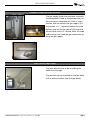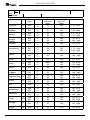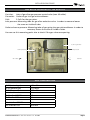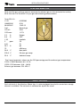
1
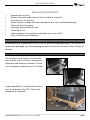
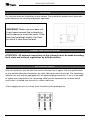
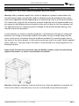
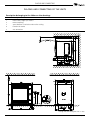
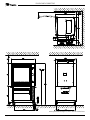
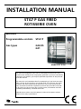
INSTALLATION MANUAL
STG7 P GAS FIRED
ROTISSERIE OVEN
MODELS
Programmable controls
Gas types
STG7 P
G20/25
G31
Model STG7 P Gas
- NOTICE This manual is prepared for the use of trained Service Technicians and
should not be used by those not properly qualified. If you have attended a
training for this product, you may be qualified to perform all the procedures in this manual.
This manual is not intended to be all encompassing. If you have not attended a training for this product, you should read, in its entirety, the repair
procedure you wish to perform to determine if you have the necessary
tools, instruments and skills required to perform the procedure. Procedures for which you do not have the necessary tools, instruments and skills
should be performed by a trained technician.
Reproduction or other use of this Manual, without the express written
consent of Fri-Jado, is prohibited.
WWW.FRIJADO.COM
Installation Manual STG7 P Gas form 9123771 rev. 02/2009
TABLE OF CONTENTS
Page 2
Installation Manual STG7 P GAS form 9123771 rev. 02/2009
TABLE OF CONTENTS
General technical data................................................................................................................. 4
Technical data ........................................................................................................................................ 4
................................................................................................................................................. 4
Installation procedures................................................................................................................ 5
Unpacking the unit................................................................................................................................. 5
Removal of pallet.................................................................................................................................... 5
Location................................................................................................................................................... 6
Electrical supply...................................................................................................................................... 6
Connection for gas supply...................................................................................................................... 7
Gas inlet pressure................................................................................................................................... 7
Gas block Honeywell type VK4115V...................................................................................................... 9
Gas consumption.................................................................................................................................... 9
Flue gas analyser................................................................................................................................... 10
Legs / Castors......................................................................................................................................... 10
Tethering of the unit............................................................................................................................ 11
Test run.................................................................................................................................................. 12
Extraction of the rotisserie................................................................................................................... 12
Instructions for operators..................................................................................................................... 12
Maintenance......................................................................................................................................... 12
Placing and connecting of the units......................................................................................... 13
Installation Manual STG7 P GAS form 9123771 rev. 02/2009
Page 3
GENERAL TECHNICAL DATA
General technical data
This manual covers the STG 7 P gas fired rotisserie ovens suitable for G 20/25 (natural gas)
and G 31 (Propane).
• STG 7 – Oven with seven spits ( 28 to 35 chickens ).
All of the information, illustrations and specifications contained in this manual are based
on the latest product information available at the time of printing.
Technical data
Type
STG 7
Power (W)
345
Fuses needed with power connection 230 V, 1N ~50…60 Hz (1 phase with zero)
1x 10 A
Standard plug from factory single pole
16A
Net weight (kg)
204
Gross weight (kg)
230
Height (mm)
1025
Width (mm)
985
Depth (mm)
850
Tools
• Standard set of tools.
• Metric wrenches, sockets and hex socket key wrenches.
• Multi-meter and AC current clamp tester.
• Temperature tester.
• Insulation value tester (Megger).
• Toxicity meter.
• Gas pressure meter.
• Field Service Grounding Kit.
Page 4
Installation Manual STG7-P gas form 9123771 rev. 02/2009
INSTALLATION PROCEDURES
Installation procedures
•
•
•
•
•
•
•
•
•
Unpacking of the unit.
Remove the pallet under the unit with the help of a fork lift.
Put the unit on his location.
Check if there is enough free space around the unit (see installation drawing).
Check the electrical supply.
Check gas pressure control valve.
Tethering of unit.
Load a program in the memory and make a test run on 250°C.
Give instructions to the operator. Unpacking the unit
Immediately after unpacking the oven, check for possible shipping damage. If the rotisserie is
found to be damaged, save the packaging material and contact the carrier within 15 days of
delivery.
Removal of pallet
The standard way to remove the rotisserie
from a pallet is with a fork lift. See pictures.
Open door and remove the drawer. Lift the
unit from pallet and put the unit in its place.
Another possibility is to disassemble the pallet. For the pallet of the STG 7 follow the
procedure on the photo.
Installation Manual STG7 P GAS form 9173771 rev. 02/2009
Page 5
INSTALLATION PROCEDURES
Location
The rotisserie must be installed on a level surface. The installation location must allow adequate clearances for servicing and proper operation.
IMPORTANT: Make sure you leave sufficient space around the rotisserie to
easily remove or insert the rotor. If the
base has (rotating) wheels, the floor
on which it rests must be level.
CONNECTING THE ROTISSERIE
ATTENTION: All external connections to the rotisserie must be made according
local, state and national regulations by skilled installers.
Electrical supply
Prior to installation, test the electrical service to assure that it agrees with the specifications
on the machine data plate located on the right side panel near the controls. The connecting
cable for the unit must be equipped with an approved plug connection. If use is to be made
of a permanent connection, the connecting cable must be connected to a manual on/off
switch that is installed near the unit in a clear visible way.
After plugging the unit in, always check the polarity for good ignition.
Page 6
Installation Manual STG7 P GAS form 9123771 rev. 02/2009
INSTALLATION PROCEDURES
Connection for gas supply
The gas supply inside the rotisserie is already
connected and is lead to the bottom side, under the electric compartment. Here is a connection tube to connect the gas supply. This
connection is ½”. Separate packed with the
delivery you will find a tube of 130 mm and
a knee, both with 1/2” thread. With this tube
and knee you can lead the gas connection to
the main gas supply.
Gas inlet pressure
The inlet pressure has to be according the
table on next page.
The pressure can be checked on the gas block
with a pressure meter (see also gas block).
Installation Manual STG7 P GAS form 9173771 rev. 02/2009
Page 7
INSTALLATION PROCEDURES
Gas-techniCAL DATA STG 7-gas
Rev.
2
PAGE 1 / 1
Date
01-02-2009
Gas
type
G20
I2H
Inlet
pressure
mbar
20
G20
G31
G20
G31
20/25
37
20
50
14.5
14.5
14.5
14.5
1.51
1.05
1.51
1.05
Czech Republic
Slovakia
CZ
Republic
I2E+
I3P
I2H
I3P
G20
G31
I2H
I3P
20
50
14.5
14.5
1.51 m3/h
1.05 kg/h
Danmark
DK
G20
I2H
20
14.5
1.51 m3/h
Deutschland
DE
G20
G25
G31
I2E
I2LL
I3P
20
20
50
14.5
14.5
14.5
1.51 m3/h
1.71 m3/h
1.05 kg/h
España
ES
G20
G31
I2H
I3P
20
50
14.5
14.5
1.51 m3/h
1.05 kg/h
Suomi
FI
G20
I2H
20
14.5
1.51 m3/h
France
FR
G20
G31
I2E
I3P
20/25
50
14.5
14.5
1.51 m3/h
1.05 kg/h
Greece
GR
G20
I2H
20
14.5
1.51 m3/h
United
Kingdom
GB
G20
G31
I2H
I3P
20
50
14.5
14.5
1.51 m3/h
1.05 kg/h
Magyarország
HU
G20
G31
I2H
I3P
20
50
14.5
14.5
1.51 m3/h
1.05 kg/h
Ireland
IE
G20
G31
I2H
I3P
20
50
14.5
14.5
1.51 m3/h
1.05 kg/h
Italia
IT
G20
I2H
20
14.5
1.51 m3/h
Luxembourg
LU
G20
G31
I2E
I3P
20
50
14.5
14.5
1.51 m3/h
1.05 kg/h
Nederland
NL
Norge
NO
G25
G31
G20
G31
I2L
I3P
I2H
I3P
25
50
20
30
14.5
14.5
14.5
14.5
1.71
1.05
1.51
1.05
Portugal
PT
G20
G31
I2H
I3P
20
37
14.5
14.5
1.51 m3/h
1.05 kg/h
Svirige
SE
G20
I2H
20
14.5
1.51 m3/h
Österreich
AT
België
Belgique
BE
Schweitz
CH
Page 8
min pressure
(Qn -Hi)
mbar
14.5
Consumption
1.51 m3/h
m3/h
kg/h
m3/h
kg/h
m3/h
kg/h
m3/h
kg/h
Installation Manual STG7 P GAS form 9123771 rev. 02/2009
INSTALLATION PROCEDURES
Gas block Honeywell type VK4115V
Gas inlet: Inlet of gas after gas pressure control valve (max. 60 mBar).
Gas outlet: Outlet of gas into gas mixture blower.
Coils: 2 Coils for the gas valves.
Inlet pressure: Measuring tube for gas after reduction valve. In order to measure loosen
the screw on inside of tube.
Outlet or burner pressure: Measuring tube of gas going into gas mixture blower. In order to measure, loosen the screw on inside of tube.
You can use this measuring point also to check if the gas valves are opening.
Coils for gas valves
Inlet pressure
Burner pressure
Gas inlet
Gas outlet
Gas consumption
G 20 (natural gas)
G 25 (natural gas)
G 31 (Propane)
1.51 m3/h
1.71 m3/h
0.55 m3/h
Orifice for G 20/25
Orifice for G 31
4.2 mm
3.4 mm
Air inlet for G 20/25
Air inlet for G 31
18.1 mm
16.5 mm
Installation Manual STG7 P GAS form 9173771 rev. 02/2009
Page 9
INSTALLATION PROCEDURES
Flue gas analyser
With the flue gas analyser you can measure the exhaust gas on the rotisserie for toxicity.
With the use of a Testo 330-1LL you get the following measurements:
Testo 330-1LL
V1.21 100035026
06.04.2007
Fuel:
O2 ref.:
CO2 max:
5.2 %
8.8 %
1.33
5
ppm
0.01
26.7 %
73
54.4 °C
378.6 °C
23.4 °C
01297080
G 20
12:42:13
Natural gas
3.0%
11.7%
Oxigen
CO2
Lambda
CO
GI
qR
efficiency
dew point
Exhaust gas temp.
Ambient temp.
The 2 most important values are the CO2 percentage and the exhaust gas temperature.
CO2% G 20/25 between 8.8 - 9.2%
CO2% G 31 between 10.4 – 10.8%
Exhaust gas between 370 - 420 °C
Legs / Castors
Each rotisserie is furnished on 50mm legs. A caster-equipped stand with convenient storage
drawer is available. The rotisserie is mounted on top of the stand.
Page 10
Installation Manual STG7 P GAS form 9123771 rev. 02/2009
INSTALLATION PROCEDURES
Tethering of the unit
(For model STG 7 units when stacked or placed on base with castors)
Warning: Safety standards require that, when this appliance is properly connected to the
electrical power supply using flexible conduit, adequate means be provided to limit movement of the appliance without depending on or transmitting stress to the electrical conduit.
This means that, as part of the installation, the base or bottom unit of stacked models must
be secured to the building structure (typically either wall or floor) to limit the movement of
the appliance and, thus, helping to prevent damage to the conduit during cleaning, maintenance and service operations.
A tether bracket, as shown on the drawing below, is provided with the base or stacking kit.
Based on the routing of the flexible conduit, the bracket must be installed along with the
caster to one corner of the base using the hardware provided. The remaining open hole in
the center of the tether bracket is to be used to secure one end of the tether (locally supplied
chain, cable, etc.). The other end of the tether is to be secured to an anchoring point in the
building structure.
Note: Length of tether must be shorter than the flexible conduit to make sure that during
appliance movement, no stress is transmitted to the conduit.
Warning: Following installation, check to confirm that, when the appliance is moved to the
limits of the tether in each direction, no stress is transmitted to the electrical conduit.
Installation Manual STG7 P GAS form 9173771 rev. 02/2009
Page 11
INSTALLATION PROCEDURES
Test run
The rotisserie must be burned in to release any odours that might result from heating the
new rotisserie surfaces.
Operate the rotisserie at maximum temperature setting of 250°C for 30 minutes. Smoke with
an unpleasant odour will normally be given off during this burn-in period.
Extraction of the rotisserie
The rotisserie must be placed in a ventilated space. The placing of an extraction hood can be
prescribed in local rules. The STG 7 produces about 10m3 water vapour per cycle.
When placing the rotisserie under an extraction hood you have to consider the following
guide lines:
- The minimum capacity of the extraction hood has to be 1000m3/h.
- The extraction hood has to extend minimum by 20 cm on all sides of the rotisserie.
- The extraction hood has to have a free height, above the rotisserie, of minimum 40 cm.
- The rotisserie has to be accessible for service purposes.
Instructions for operators
After installation of the rotisserie the operator of the unit has to be instructed.
The instruction has to cover the following subjects:
•
•
•
•
•
•
Programming and options.
Working of the unit.
Free space of unit for cooling of drive motor and blowers.
Run through the user manual.
Periodical maintenance:
o
Cleaning of fan plate every month.
o
Cleaning of fans on blower every month.
How to react for information or service calls.
Maintenance
The customer should have the gas rotisserie periodically checked by a skilled technician according local, state or national regulations.
First remove the right side panel according the service manual.
• Check for gas leaks and/or bad connections of the gas supply inside and outside.
• Check the gas burner.
• Check the inlet pressure and re-adjust if necessary. For the correct value, see table page 8.
• Measure the exhaust gas with a flue gas analyzer, see page 10.
• Check the electrical supply.
Page 12
Installation Manual STG7 P GAS form 9123771 rev. 02/2009
PLACING AND CONNECTING
Placing and connecting of the units
Description belonging to the lables on the drawings
Label
Description
1
Power cable, length 2,2 meters *
2
Exhaust opening
3
Space between a rotisserie and a wall or ceiling
4
Location for socket
5
Gas connection
*) length is measured from the point where the cable comes out of the unit
Placing and connecting the STG 7 P Gas
Installation Manual STG7 P GAS form 9123771 rev. 02/2009
Page 13
PLACING AND CONNECTING
Placing and connecting the STG7 P Gas on underframe
Page 14
Installation Manual STG7 P GAS form 9123771 rev. 02/2009
GENERAL TECHNICAL DATA
Installation Manual STG7 P GAS form 9123771 rev. 02/2009
Page 15
Fri-Jado B.V. • P.O. Box 560 • 4870 AN • Etten-Leur • The Netherlands • tel +31 76 50 85 400 • fax +31 76 50 85 444 • [email protected] • www.frijado.com
Page 16
Installation Manual STG7 P GAS form 9123771 rev. 02/2009