1
{ServiceManual}{Production}{Health Group}{Confidential}
Publication No. 8H8442
4AUG2010
CARESTREAM DIRECTVIEW VITA CR System
Service Guide
14
14 x17
x1
4
11
x1
4
8x
10 10
24 x12
x3
0
8x
10 10
24 x12
x3
0
11
x1
4
14
14 x17
x1
4
Important
• Qualified service personnel must install this modification.
• See the Service Portal for possible updates before doing this modification.
• When doing the procedures in this document, you must use safe work practices and wear the correct personal
protective equipment (for example, safety eyewear) according to your company’s standard operating
procedures.
Confidential
© CARESTREAM HEALTH, INC. 2010
SERVICE MANUAL
CARESTREAM DIRECTVIEW VITA CR System Service Guide
Document No.: 8H8442
Copyright Carestream Health, Inc. 2010
All rights reserved. No part of this manual may be reproduced or copied in any form by any means–graphic, electronic
or mechanical, including photocopying, typing, or information retrieval systems–without written permission of
Carestream Health.
Use of Manual
CARESTREAM CR Systems are designed to meet international safety and performance standards. Personnel
operating the unit must have a thorough understanding of the proper operation of the system. This manual has been
prepared to aid medical and technical personnel to understand and operate the system. Do not operate the system
before reading this manual and gaining a clear understanding of the operation of the system. If any part of this manual
is not clear, please contact your Carestream Health representative for clarification.
Authorized Representatives
LES MERCURIALES
40, rue Jean Jaures
93176 BAGNOLET CEDEX
France
Carestream Health, Inc.
Rochester, NY 14608
CARESTREAM is a trademark of Carestream Health.
© Carestream Health, Inc., 2010
ii
4AUG2010 – 8H8442
Table of Contents
Description
Safety and Regulatory Information . . . . . . . . . . . . . . . . . . . . . . . . . . . . . . . . . . . . . . . . . . .
Introduction . . . . . . . . . . . . . . . . . . . . . . . . . . . . . . . . . . . . . . . . . . . . . . . . . . . . . . . . .
Document Conventions . . . . . . . . . . . . . . . . . . . . . . . . . . . . . . . . . . . . . . . . . . . . . . .
General Safety Guidelines . . . . . . . . . . . . . . . . . . . . . . . . . . . . . . . . . . . . . . . . . . . . .
Electrical Hazards. . . . . . . . . . . . . . . . . . . . . . . . . . . . . . . . . . . . . . . . . . . . . . . . . . . .
Explosion and Implosion Hazards . . . . . . . . . . . . . . . . . . . . . . . . . . . . . . . . . . . . . . .
Overheating . . . . . . . . . . . . . . . . . . . . . . . . . . . . . . . . . . . . . . . . . . . . . . . . . . . . . . . .
Vita CR Laser Safety Instructions. . . . . . . . . . . . . . . . . . . . . . . . . . . . . . . . . . . . . . . .
Device-Specific Safety Information. . . . . . . . . . . . . . . . . . . . . . . . . . . . . . . . . . . . . . .
Health and Safety Compliance . . . . . . . . . . . . . . . . . . . . . . . . . . . . . . . . . . . . . . . . . .
CE Conformity . . . . . . . . . . . . . . . . . . . . . . . . . . . . . . . . . . . . . . . . . . . . . . . . . . . . . .
IEC Symbols Used . . . . . . . . . . . . . . . . . . . . . . . . . . . . . . . . . . . . . . . . . . . . . . . . . . .
Labelling Summary . . . . . . . . . . . . . . . . . . . . . . . . . . . . . . . . . . . . . . . . . . . . . . . . . . .
Recycling the Scanner . . . . . . . . . . . . . . . . . . . . . . . . . . . . . . . . . . . . . . . . . . . . . . . .
Vita CR System Introduction . . . . . . . . . . . . . . . . . . . . . . . . . . . . . . . . . . . . . . . . . . . . . . .
Introduction . . . . . . . . . . . . . . . . . . . . . . . . . . . . . . . . . . . . . . . . . . . . . . . . . . . . . . . . .
Operational Principles. . . . . . . . . . . . . . . . . . . . . . . . . . . . . . . . . . . . . . . . . . . . . . . . .
Vita CR System Overview and Component Descriptions . . . . . . . . . . . . . . . . . . . . . . . . . .
System Overview . . . . . . . . . . . . . . . . . . . . . . . . . . . . . . . . . . . . . . . . . . . . . . . . . . . .
Part and System Descriptions . . . . . . . . . . . . . . . . . . . . . . . . . . . . . . . . . . . . . . . . . .
Block Diagram of the Vita CR System . . . . . . . . . . . . . . . . . . . . . . . . . . . . . . . . . . . .
Vita CR Service Procedures. . . . . . . . . . . . . . . . . . . . . . . . . . . . . . . . . . . . . . . . . . . . . . . .
Service Tools and Preparation . . . . . . . . . . . . . . . . . . . . . . . . . . . . . . . . . . . . . . . . . .
Replacing the Scanner Cover. . . . . . . . . . . . . . . . . . . . . . . . . . . . . . . . . . . . . . . . . . .
Activating the Scanner without the Cover. . . . . . . . . . . . . . . . . . . . . . . . . . . . . . . . . .
Replacing the Scanner Base . . . . . . . . . . . . . . . . . . . . . . . . . . . . . . . . . . . . . . . . . . .
Replacing the Power Line Filter Module . . . . . . . . . . . . . . . . . . . . . . . . . . . . . . . . . . .
Replacing the Fuse. . . . . . . . . . . . . . . . . . . . . . . . . . . . . . . . . . . . . . . . . . . . . . . . . . .
Replacing the Controller Board. . . . . . . . . . . . . . . . . . . . . . . . . . . . . . . . . . . . . . . . . .
Replacing the Controller Board Bracket . . . . . . . . . . . . . . . . . . . . . . . . . . . . . . . . . . .
Replacing the Photo Multiplier Board . . . . . . . . . . . . . . . . . . . . . . . . . . . . . . . . . . . . .
Replacing the Photo Multiplier Assembly . . . . . . . . . . . . . . . . . . . . . . . . . . . . . . . . . .
Replacing the Optical Assembly . . . . . . . . . . . . . . . . . . . . . . . . . . . . . . . . . . . . . . . .
Replacing the Linear Screw Assembly . . . . . . . . . . . . . . . . . . . . . . . . . . . . . . . . . . . .
Replacing the Linear Motor. . . . . . . . . . . . . . . . . . . . . . . . . . . . . . . . . . . . . . . . . . . . .
Replacing the Roller Motor Assembly. . . . . . . . . . . . . . . . . . . . . . . . . . . . . . . . . . . . .
Replacing the Loader Assembly . . . . . . . . . . . . . . . . . . . . . . . . . . . . . . . . . . . . . . . . .
Replacing the Laser Driver Board. . . . . . . . . . . . . . . . . . . . . . . . . . . . . . . . . . . . . . . .
Replacing the Power Supply. . . . . . . . . . . . . . . . . . . . . . . . . . . . . . . . . . . . . . . . . . . .
Replacing the 24V Power Supply Unit . . . . . . . . . . . . . . . . . . . . . . . . . . . . . . . . . . . .
Replacing the Erase LED Assembly. . . . . . . . . . . . . . . . . . . . . . . . . . . . . . . . . . . . . .
Replacing the Roof Assembly. . . . . . . . . . . . . . . . . . . . . . . . . . . . . . . . . . . . . . . . . . .
Replacing the Barcode Reader. . . . . . . . . . . . . . . . . . . . . . . . . . . . . . . . . . . . . . . . . .
Replacing the Sensor Z4 . . . . . . . . . . . . . . . . . . . . . . . . . . . . . . . . . . . . . . . . . . . . . .
Replacing the Sensor Z0 . . . . . . . . . . . . . . . . . . . . . . . . . . . . . . . . . . . . . . . . . . . . . .
Installing the Sensor Z0 . . . . . . . . . . . . . . . . . . . . . . . . . . . . . . . . . . . . . . . . . . . . . . .
Replacing the Right and Left Limit Switch Sensors . . . . . . . . . . . . . . . . . . . . . . . . . .
Replacing the Screen Carriage. . . . . . . . . . . . . . . . . . . . . . . . . . . . . . . . . . . . . . . . . .
Rollers Replacement . . . . . . . . . . . . . . . . . . . . . . . . . . . . . . . . . . . . . . . . . . . . . . . . .
Vita CR Adjustments . . . . . . . . . . . . . . . . . . . . . . . . . . . . . . . . . . . . . . . . . . . . . . . . . . . . .
Loader Pusher Adjustment . . . . . . . . . . . . . . . . . . . . . . . . . . . . . . . . . . . . . . . . . . . . .
Maintaining and Cleaning the System . . . . . . . . . . . . . . . . . . . . . . . . . . . . . . . . . . . . . . . .
Cleaning the VITA CR Rollers . . . . . . . . . . . . . . . . . . . . . . . . . . . . . . . . . . . . . . . . . .
8H8442 – 4AUG2010
Page
1
1
1
1
2
6
6
6
6
7
7
8
9
9
11
11
11
13
13
15
17
19
19
20
21
23
24
26
27
30
31
33
36
39
44
46
50
53
55
57
59
62
67
69
71
72
73
76
79
89
89
91
91
iii
SERVICE MANUAL
Cleaning the VITA CR . . . . . . . . . . . . . . . . . . . . . . . . . . . . . . . . . . . . . . . . . . . . . . . .
93
Key Operator Settings . . . . . . . . . . . . . . . . . . . . . . . . . . . . . . . . . . . . . . . . . . . . . . . . . . . .
95
Accessing Advanced Settings . . . . . . . . . . . . . . . . . . . . . . . . . . . . . . . . . . . . . . . . . .
95
User Tab . . . . . . . . . . . . . . . . . . . . . . . . . . . . . . . . . . . . . . . . . . . . . . . . . . . . . . . . . .
96
Setup Tab. . . . . . . . . . . . . . . . . . . . . . . . . . . . . . . . . . . . . . . . . . . . . . . . . . . . . . . . . .
98
Anatomical Tab . . . . . . . . . . . . . . . . . . . . . . . . . . . . . . . . . . . . . . . . . . . . . . . . . . . . . 100
Diagnostics Tab . . . . . . . . . . . . . . . . . . . . . . . . . . . . . . . . . . . . . . . . . . . . . . . . . . . . . 102
SW Update & Backup Tab . . . . . . . . . . . . . . . . . . . . . . . . . . . . . . . . . . . . . . . . . . . . . 106
Calibration Tab. . . . . . . . . . . . . . . . . . . . . . . . . . . . . . . . . . . . . . . . . . . . . . . . . . . . . . 109
Admin Tab . . . . . . . . . . . . . . . . . . . . . . . . . . . . . . . . . . . . . . . . . . . . . . . . . . . . . . . . . 110
About Tab. . . . . . . . . . . . . . . . . . . . . . . . . . . . . . . . . . . . . . . . . . . . . . . . . . . . . . . . . . 111
Configuring DICOM . . . . . . . . . . . . . . . . . . . . . . . . . . . . . . . . . . . . . . . . . . . . . . . . . . . . . . 113
Configuring DICOM Settings for Modality Work List (MWL) . . . . . . . . . . . . . . . . . . . 113
DICOM and PACS Workstation Destinations. . . . . . . . . . . . . . . . . . . . . . . . . . . . . . . 115
Calibrations . . . . . . . . . . . . . . . . . . . . . . . . . . . . . . . . . . . . . . . . . . . . . . . . . . . . . . . . . . . . 117
Introduction . . . . . . . . . . . . . . . . . . . . . . . . . . . . . . . . . . . . . . . . . . . . . . . . . . . . . . . . 117
Origin Calibration . . . . . . . . . . . . . . . . . . . . . . . . . . . . . . . . . . . . . . . . . . . . . . . . . . . . 118
Offset Calibration . . . . . . . . . . . . . . . . . . . . . . . . . . . . . . . . . . . . . . . . . . . . . . . . . . . . 120
System Gain Tuning. . . . . . . . . . . . . . . . . . . . . . . . . . . . . . . . . . . . . . . . . . . . . . . . . . 122
System Performance Acceptance Testing Procedure (ATP) . . . . . . . . . . . . . . . . . . . . . . . 123
Scope of the Acceptance Testing Procedure (ATP) . . . . . . . . . . . . . . . . . . . . . . . . . 123
Gather Tools and Materials Required to Perform the ATP . . . . . . . . . . . . . . . . . . . . 123
Prepare the CR System for ATP Testing . . . . . . . . . . . . . . . . . . . . . . . . . . . . . . . . . . 124
Perform the “Dark Noise” Test . . . . . . . . . . . . . . . . . . . . . . . . . . . . . . . . . . . . . . . . . . 125
Basic X-Ray Exposure Procedure . . . . . . . . . . . . . . . . . . . . . . . . . . . . . . . . . . . . . . . 125
Spatial Frequency Resolution, Exposure Response, and Contrast Resolution Testing:
Prepare the Cassette . . . . . . . . . . . . . . . . . . . . . . . . . . . . . . . . . . . . . . . . . . . . . . . 126
ATP Testing: General Examination of the Scanned Image . . . . . . . . . . . . . . . . . . . . 127
ATP Testing: Inspect the Spatial Resolution of the Scanned Image . . . . . . . . . . . . . 128
ATP Testing: Inspect the Low Contrast Resolution of the Scanned Image . . . . . . . . 129
ATP Testing: Inspect the Exposure Response of the Scanned Image . . . . . . . . . . . 130
Test the Erasure Efficiency of the System . . . . . . . . . . . . . . . . . . . . . . . . . . . . . . . . . 131
Performing an ROI Analysis. . . . . . . . . . . . . . . . . . . . . . . . . . . . . . . . . . . . . . . . . . . . 132
Using the WIISE Diagnostics Tool . . . . . . . . . . . . . . . . . . . . . . . . . . . . . . . . . . . . . . . . . . . 133
Using WIISE to Verify Correct System Performance and Calibration . . . . . . . . . . . . 133
Launching the WIISE Viewer Application . . . . . . . . . . . . . . . . . . . . . . . . . . . . . . . . . 133
Opening an Image in the WIISE Viewer Application . . . . . . . . . . . . . . . . . . . . . . . . . 133
Using the Region of Interest (ROI) Tool in the WIISE Viewer Application . . . . . . . . 134
Adjusting the Window Size/Scaling in the WIISE Viewer Application . . . . . . . . . . . . 135
Adjusting the Window Width and Leveling in the WIISE Viewer Application . . . . . . 135
Using the Line Profiles Tool in the WIISE Viewer Application. . . . . . . . . . . . . . . . . . 135
Spare Parts . . . . . . . . . . . . . . . . . . . . . . . . . . . . . . . . . . . . . . . . . . . . . . . . . . . . . . . . . . . . 137
Electronics Board . . . . . . . . . . . . . . . . . . . . . . . . . . . . . . . . . . . . . . . . . . . . . . . . . . . . 137
Optics . . . . . . . . . . . . . . . . . . . . . . . . . . . . . . . . . . . . . . . . . . . . . . . . . . . . . . . . . . . . . 137
Power Supply . . . . . . . . . . . . . . . . . . . . . . . . . . . . . . . . . . . . . . . . . . . . . . . . . . . . . . . 137
Sensors . . . . . . . . . . . . . . . . . . . . . . . . . . . . . . . . . . . . . . . . . . . . . . . . . . . . . . . . . . . 138
Motors . . . . . . . . . . . . . . . . . . . . . . . . . . . . . . . . . . . . . . . . . . . . . . . . . . . . . . . . . . . . 138
Covers . . . . . . . . . . . . . . . . . . . . . . . . . . . . . . . . . . . . . . . . . . . . . . . . . . . . . . . . . . . . 139
Mechanic Accessories . . . . . . . . . . . . . . . . . . . . . . . . . . . . . . . . . . . . . . . . . . . . . . . . 139
Others . . . . . . . . . . . . . . . . . . . . . . . . . . . . . . . . . . . . . . . . . . . . . . . . . . . . . . . . . . . . 140
Electric Schematic Diagrams . . . . . . . . . . . . . . . . . . . . . . . . . . . . . . . . . . . . . . . . . . . . . . 141
Calibration Results Form . . . . . . . . . . . . . . . . . . . . . . . . . . . . . . . . . . . . . . . . . . . . . . . . . . 145
Calibration Results Report . . . . . . . . . . . . . . . . . . . . . . . . . . . . . . . . . . . . . . . . . . . . . 145
Publication History . . . . . . . . . . . . . . . . . . . . . . . . . . . . . . . . . . . . . . . . . . . . . . . . . . . . . . . 147
iv
4AUG2010 – 8H8442
Safety and Regulatory Information
Section 1: Safety and Regulatory Information
Introduction
The information contained herein is based on the experience and knowledge relating to the subject matter gained by
Carestream Health prior to publication. No patent license is granted by this information.
Carestream Health reserves the right to change this information without notice, and makes no warranty, express or
implied, with respect to this information. Carestream Health shall not be liable for any loss or damage, including
consequential or special damages, resulting from any use of this information, even if loss or damage is caused by
Carestream Health’s negligence or other fault.
Document Conventions
In this document the CARESTREAM DIRECTVIEW VITA CR SYSTEM will be referred to as “Vita CR”, “CR
Scanner”, or “System”.
Note
Notes provide additional information, such as expanded explanations, hints, or reminders.
Caution
Cautions point out procedures that you must follow precisely to avoid damage to the system or any of its components,
yourself or others, loss of data or corruption of files in software applications.
Important
Important highlights critical policy information that affects how you use this manual and this product.
General Safety Guidelines
• This product is designed and manufactured to ensure maximum safety of operation. Operate and maintain it in
strict compliance with the safety precautions and operating instructions contained in this manual.
• This product meets all the safety requirements applicable to medical equipment. However, anyone attempting to
operate the system must be fully aware of potential safety hazards.
• Aside from cleaning the phosphor screen and the system’s rollers, there are no user serviceable parts in this
system. The product must be installed, maintained, and serviced by qualified service personnel according to
procedures and preventive maintenance schedules in the product service manual. If your product does not
operate as expected, contact your Service Representative.
• Do not modify this product in whole or in part without prior written approval from Carestream Health.
• Personnel operating and maintaining this system should receive training and be familiar with all aspects of
operation and maintenance.
• To ensure safety, read all user manuals carefully before using the system and observe all Cautions, Importants,
and Notes located throughout the manual.
• Keep this manual with the equipment.
• Reading this manual does not qualify you to operate, test, or calibrate this system.
• Unauthorized personnel are not allowed access to the system.
• If the product does not operate properly or fails to respond to the controls as described in this manual:
– Follow the safety precautions as specified in this manual.
– Stop using the unit and prevent any changes to it.
– Immediately contact the service office, report the problem, and await further instructions.
• Use only legally marketed cassettes. Check periodically the quality of the cassettes, and replace them if any
defects are apparent.
8H8439 – 27JUN2010
1
MISCELLANEOUS PUBLICATION
• The images provided by this system are intended as tools for the trained user. They are explicitly not to be
regarded as a sole incontrovertible basis for clinical diagnosis.
• Be aware of the product specifications and of system accuracy and stability limitations. Consider these limitations
before making any decision based on quantitative values. If you have any doubts, consult your Sales
Representative.
• This system is Class I continuous operated stationary equipment without applied parts and has one signal input/
output part.
• The appliance coupler of the flexible cord is used as a disconnecting device.
• In order to guarantee medical-grade leakage current, the computer that is connected to the system should be a
medical-grade computer or connected to the mains through a medical-grade isolation transformer.
• To achieve grounding reliability in USA installations, the equipment must be connected to an equivalent
receptacle marked “Hospital Only” or “Hospital Grade”.
Important
When the System is not in use, disconnect the power cable from the electrical outlet.
Electrical Hazards
Caution
• Do not remove or open system covers or plugs. Internal circuits use high voltage capable of causing serious
injury.
• Fuses blown within 36 hours of being replaced by a qualified technician may indicate malfunctioning electrical
circuits within the system. Have the system checked by qualified service personnel. Do not attempt to replace
any fuse.
• Fluids that seep into the active circuit components of the system may cause short circuits that can result in
electrical fires. Therefore, do not place any liquid or food on any part of the system.
Electromagnetic Emissions/Immunity
• Electromagnetic Compatibility Precautions
– Medical electrical equipment requires special precautions regarding electromagnetic compatibility (EMC).
Medical equipment must be installed and put into service according to the EMC information provided in the
following documentation.
• Communications Equipment
– Portable and mobile radio frequency (RF) communications equipment can affect medical electrical
equipment EMC performance.
• Replacement of Cables, Accessories or Transducers
– The use of cables, accessories or transducers other than those specified below with the exception of
transducers or cables sold by the manufacturer of the equipment as replacement parts for internal
components, may result in increased emissions or decreased immunity of the medical equipment.
• Other Equipment
– The Vita CR should not be used adjacent to or stacked on other equipment. If adjacent or stacked use is
necessary, verify normal operation in the configuration in which the scanner will be used.
• Cable, Accessory and Transducer Information for the Vita CR.
Port Type
Port
Description
From
To
Cable Type
Cable Length
Power
AC Power
Vita CR
AC Mains
Unshielded
3 m (9.84 ft.)
Signal
USB
Vita CR
PC
Shielded
3 m (9.84 ft.)
2
27JUN2010 – 8H8439
Safety and Regulatory Information
Guidance and manufacturer’s declaration - electromagnetic emissions
The Vita CR is intended for use in the electromagnetic environment specified below. The customer or the user of
the Vita CR should assure that it is used in such an environment.
Emissions test
Compliance
RF emissions
Group 1
The Vita CR uses RF energy only for its internal
function. Therefore, its RF emissions are very low and
are not likely to cause any interference in nearby
electronic equipment.
Class B
The Vita CR is suitable for use in all establishments,
including domestic establishments and those directly
connected to the public low-voltage power supply
network that supplies buildings for domestic purposes.
CISPR 11
RF emissions
CISPR 11
Harmonics emissions
Electromagnetic environment - guidance
Class A
IEC 61000-3-2
Voltage fluctuations/
flicker emissions
Complies
IEC 61000-3-3
Guidance and manufacturer’s declaration - electromagnetic immunity
The Vita CR is intended for use in the electromagnetic environment specified below. The customer or the user of
the Scanner should assure that it is used in such an environment.
Immunity test
IEC 60601 test level
Compliance level
Electromagnetic environment guidance
±6 kV contact
±6 kV contact
±8 kV air
±8 kV air
Electrical fast
transient/burst
±2 kV for power supply
lines
±2 kV for power
supply lines
IEC 61000-4-4
±1 kV for input/output
lines
Mains power quality should be that
of a typical commercial or hospital
±1 kV for input/output environment.
lines
Surge
±1 kV line to line
±1 kV line to line
IEC 61000-4-5
±2 kV line to earth
±2 kV line to earth
Voltage dips,
short
interruptions
and voltage
variations on
power supply
lines
<5% UT (>95% dip in
UT) for 0.5 cycle
40% UT (60% dip in
UT) for 5 cycles
IEC 61000-4-11
<5% UT (>95% dip in
UT) for 5 sec.
<5% UT (>95% dip in Mains power quality should be that
of a typical commercial or hospital
UT) for 0.5 cycle
40% UT (60% dip in environment. If the user of the Vita
CR requires continued operation
UT) for 5 cycles
during power mains interruptions, it
70% UT (30% dip in is recommended that the Vita CR be
UT) for 25 cycles
powered from an uninterruptible
<5% UT (>95% dip in power supply.
UT) for 5 sec.
Electrostatic
discharge (ESD)
IEC 61000-4-2
70% UT (30% dip in
UT) for 25 cycles
3 A/m
Power
frequency (50/
60 Hz) magnetic
field
3 A/m
Floors should be wood, concrete or
ceramic tile. If floors are covered
with synthetic material, the relative
humidity should be at least 30%.
Mains power quality should be that
of a typical commercial or hospital
environment.
Power frequency magnetic fields
should be at levels characteristic of
a typical location in a typical
commercial or hospital environment.
IEC 61000-4-8
Note: UT is the AC mains voltage prior to application of the test level.
8H8439 – 27JUN2010
3
MISCELLANEOUS PUBLICATION
Guidance and manufacturer’s declaration - electromagnetic immunity
The CR System is intended for use in the electromagnetic environment specified below. The customer or the
user should assure that it is used in such an environment.
Immunity test
IEC 60601 test level
Compliance
level
Electromagnetic environment - guidance
Portable and mobile RF communications equipment
should be used no closer to any part of the Vita CR,
including cables, than the recommended separation
distance calculated from the equation applicable to
the frequency of the transmitter.
Recommended separation distance
Conducted RF IEC
61000-4-6
3 Vrms
Radiated RF IEC
61000-4-3
3 Vrms
3 Vrms
d = 1.17 ÷P
3 v/m
d = 1.17 ÷P 80 MHz to 800 MHz
15 kHz to 80 MHz
80 MHz to 2.5
GHz
d = 2.33 ÷P 800 M Hz to 2.5 GHz
where P is the maximum output rating of the
transmitter in watts (W) according to the transmitter
manufacturer and d is the recommended separation
distance in meters (m).
Field strengths from fixed RF transmitters, as
determined by an electromagnetic site
surveya,should be less than the compliance level in
each frequency rangeb.
Interference may occur in the vicinity of equipment
marked with the following symbol:
Note 1: At 80 MHz and 800 MHz, the higher frequency range applies.
Note 2: These guidelines may not apply in all situations. Electromagnetic propagation is affected by absorption
and reflection from structures, objects and people.
a.Field from fixed transmitters, such as base station for radio (cellular/cordless) telephones and land mobile radios,
amateur radio, AM and FM radio broadcast and TV broadcast cannot be predicted theoretically with accuracy. To
assess the electromagnetic environment due to fixed RF transmitters, an electromagnetic site survey should be
considered. If the measured field strength in the location in which the scanner is used exceeds the applicable RF
compliance level above, the scanner should be observed to verify normal operation. If abnormal performance is
observed, additional measures may be necessary, such as reorienting or relocating the scanner.
b. Over the frequency range 150 kHz to 80 MHz, field strengths should be less than 3 v/m.
4
27JUN2010 – 8H8439
Safety and Regulatory Information
Recommended separation distance between portable and mobile RF communications equipment and the
Vita CR
The Vita CR is intended for use in an electromagnetic environment in which radiated RF disturbances are
controlled. The customer or the user of the Vita CR can help prevent electromagnetic interference by maintaining
a minimum distance between portable and mobile RF communication equipment (transmitters) and the Vita CR as
recommended below, according to the maximum output of the communications equipment.
W Rated maximum output
power of transmitter
m Separation distance according to frequency of transmitter
150 kHz to 80 MHz
80 MHz to 800 MHz
d = 1.17÷P
d = 1.17÷P
800 MHz to 2.5 GHz
d = 2.33÷P
0.01
0.117
0.117
0.233
0.1
0.37
0.37
0.737
1
1.17
1.17
2.33
10
3.7
3.7
7.36
100
11.7
11.7
23.3
For transmitters rated at a maximum output power not listed above, the recommended separation distance d in
meters (m) can be estimated using the equation applicable to the frequency of the transmitter, where P is the
maximum output power rating of the transmitter in watts (W) according to the transmitter manufacturer.
Note 1: At 80 MHz and 800 MHz, the separation distance for the higher frequency range applies.
Note 2: These guidelines may not apply in all situations. Electromagnetic propagation is affected by absorption
and reflection from structures, objects and people.
8H8439 – 27JUN2010
5
MISCELLANEOUS PUBLICATION
Explosion and Implosion Hazards
Caution
• Do not operate the equipment in the presence of explosive liquids, vapors, or gases.
• Do not plug in or turn on the system if hazardous substances are detected in the environment. If these
substances are detected after the system has been turned on, do not attempt to turn off the unit or unplug it.
Evacuate and ventilate the area before turning off the system.
Overheating
Caution
Do not block the air circulation around the unit. Always maintain at least 15 cm (6 in.) clearance around the unit to
prevent overheating and damage to the system.
Vita CR Laser Safety Instructions
The Vita CR is classified as a Class 1 Laser Product (with the outer cover in place).
Laser Warning
• The Vita CR contains a Class 3 laser. During normal operation, always keep the unit enclosed in its protective
cover.
• Do not attempt to remove the cover. Only a qualified technician may remove the cover to service this product.
Complies with 21 CFR 1040.10 and 1040.11 except for deviations pursuant to Laser Notice No. 50, dated
June 24, 2007.
Class 1 Laser Product, and IEC/EN 60825-1.
Class 1 Equipment.
Intended for continuous operation.
Product is provided with ordinary protection against the harmful ingress of water.
Not suitable for use in the presence of a flammable anesthetics mixture with air or with oxygen or with nitrous oxide.
The use of accessory equipment not complying with the equivalent safety requirements of this equipment may lead
to a reduced level of safety of the resulting system. Consideration relating to the choice shall include:
• Use of the accessory in the patient vicinity.
• Evidence that the safety certification of the accessory has been performed in accordance with IEC 60601-1 or
the system to IEC 60601-1-1 or local equivalent.
Device-Specific Safety Information
LIFTING HAZARD
The Vita CR weighs <36 kg (79 lb). Do not try to lift the unit by yourself.
Always seek assistance from another person. Lifting equipment that is
too heavy may result in serious injury and/or damage to equipment.
6
27JUN2010 – 8H8439
Safety and Regulatory Information
Health and Safety Compliance
Regulatory Information
The Vita CR was examined for compliance and has classifications and licenses as follows:
Safety
USA
UL 60601-1: 2003 Medical Electrical Equipment
Canada
CAN/CSA 22.2 No. 601.1-M90 - Medical Electrical Equipment (R2001)
CAN/CSA 22.2 No. 601.1S1-94 - Supplement No. 1-94 to Medical Electrical Equipment (R1999)
CAN/CSA 22.2 No. 601.1B-90 - Amendment 2 to Medical Electrical Equipment (R2002)
International IEC 60601-1: 1988, +A1 (1991), +A2 (1995) Medical Electrical Equipment
IEC 60825-1: 1993 +A1:1997 + A2:2001 Safety of Laser Products
European
Union
EN 60601-1-1: 2001 - Medical Electrical Equipment
EN 60601-1: 1990 +A1: 1993, +A2: 1995, +A13: 1996 - Medical Electrical Equipment
EN 60825-1: 1994 +A1: 1997 + A2: 2001 Safety of Laser Products
EMC
IEC 60601-1-2: 2005 Medical Electrical Equipment - Electro-Magnetic Compatibility Requirements & Tests.
IEC 60825-1-2: 2001 Safety of Laser Products - Part 1: Equipment Classification, Requirements and User’s Guide.
CE Conformity
This product conforms to the requirements of Council Directive 93/42/EEC. The Vita CR is a Class I medical device.
The Vita CR bears the following mark of conformity.
8H8439 – 27JUN2010
7
MISCELLANEOUS PUBLICATION
IEC Symbols Used
The system may have labels with one or more of the following symbols. These symbols indicate the IEC standards
to which the system conforms.
Caution – consult accompanying documents
Protective earth points
Power On
Power Off
Caution – Electrical shock hazard
8
27JUN2010 – 8H8439
Safety and Regulatory Information
Labelling Summary
External Labels
Product data plate
Internal Safety Labels
Laser-emitting product
Class 3B laser product inside
unit
High voltage
Protective earth point (chassis
stud)
Recycling the Scanner
In the European Union, this symbol indicates that when the last user wishes to discard this product, it must be sent
to appropriate facilities for recovery and recycling. Contact your local representative for additional information on the
collection and recovery programs available for this product.
8H8439 – 27JUN2010
9
MISCELLANEOUS PUBLICATION
10
27JUN2010 – 8H8439
Vita CR System Introduction
Section 2: Vita CR System Introduction
Introduction
Note
Throughout this manual the CARESTREAM DIRECTVIEW VITA CR System will be referred to as “Vita CR” or
“System.”
The System is designed for the reading of phosphor X-ray screens (CR) by medical professionals.
The System consists of the Vita CR Scanner and a software package that includes:
• CARESTREAM VITA CR Systems Software that operates the scanner.
• An image viewing and archiving software package that supports the DICOM 3.1 standard and was approved by
Carestream Health.
• The system features 8 x 10 in., 10 x 12 in., 14 x 17 in., 11 x 14 in., 14 x 14 in., 14 x 33 in., 24 x 30 cm,
15 x 30 cm digital image reading and viewing archive.
Features/Function
Description
Power Source
110–250 V, 4 A input source
Image Capture
40 images/hour
Image Storing
Stores 500 (configurable).
Operating System
MICROSOFT WINDOWS XP Professional with Service Pack 3, WINDOWS VISTA
Business SP1, WINDOWS 7
Service Interface
Scanner: PC
Electrical Service
50–60 Hz
Note
Throughout this manual, the Front of the unit refers to the side where the cassettes are inserted. Right and Left are
as viewed when facing the front of the unit.
Operational Principles
The VITA CR System is a digital imaging system used for image acquisition and processing of static projection
radiography images. The System utilizes a phosphor screen with energy storage capability as an X-ray image
receptor.
After exposure, a laser beam stimulates the phosphor screen, creating luminescence (“blue light”) proportional to the
local X-ray exposure. The luminescence signal is captured by a Photo Multiplier Tube (PMT), digitized, and
processed for review.
The System enables you to read a storage phosphor screen quickly and erase it for the next exposure.
8H8442 – 4AUG2010
11
SERVICE MANUAL
12
4AUG2010 – 8H8442
Vita CR System Overview and Component Descriptions
Section 3: Vita CR System Overview and Component Descriptions
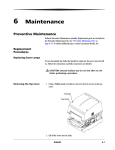
System Overview
Scanner Front View
Drum
Laser
driver board
Linear motor
Linear
screw
Roof assembly
LED indicator
Tray assembly
Cassette release knob
Scanner Rear View
PMT assembly
5V, ± 15V
Power supply
unit
Controller board
iButton
Off/On switch
USB outlet
Power cord
socket
8H8442 – 4AUG2010
Screen
carriage
24V power
supply unit
13
SERVICE MANUAL
Scanner Left View
PM board
Blue flex cable
Back rollers
Erase LED
assembly
Controller board
Roller drive
motor
Scanner Right View
Blue Flex Cable
Front Rollers
Laser Driver Board
Laser Head
Assembly
5V, ± 15V
Power Supply
Unit
14
4AUG2010 – 8H8442
Vita CR System Overview and Component Descriptions
Part and System Descriptions
Part Name
Controller Board
Description
The controller board receives operational commands from the host computer
workstation via the USB cable, and transforms the commands to the appropriate
scanner hardware commands.
The controller board builds the scanned images and sends them via the same
USB cable to the computer workstation.
The controller board controls and drives the four motors:
• Loader motor
• Linear motor
• Rotational motor
• Roller drive motor
The controller board receives feedback from the encoders and sensors.
The controller board monitors the erasing LED current and temperature.
Laser
The laser beam stimulates the phosphor screen.
Laser Driver Board
The laser driver board receives rotation motor phases, laser power, and enables
laser signals. It transfers the rotation motor encoder signals to the controller
board.
Laser Head Assembly
The laser head assembly includes the laser module and the rotational motor that
rotates a mirror during scanning. The laser beam emitted from the laser module is
reflected by the revolving mirror to different points on the phosphor screen inside
of the drum. Simultaneously, the laser head assembly travels along a linear axis,
therefore the laser beam covers the full area of the screen on one line at a time
(fast scan). Another mirror collects and reflects the light returned from the screen
to the PM assembly window.
Photo Multiplier (PM)
Assembly
The photo multiplier (PM) tube collects the light (photons) emitted from the screen
and transforms the light into a current which is then converted to voltage and
digitized by an Analog to Digital Converter (ADC) to pixel value.
Linear Slide Assembly
The linear slide assembly moves the laser head and PM assembly along the
x-axis (slow scan) during the scan.
Barcode Reader
The barcode reader reads the screen size after the cassette is inserted into the
scanner and locked into place.
LED Indicator
The LED indicator indicates the scanner’s main status such as ready for scan,
erasing and so on.
Power Supply
The power supply provides Vdc power to the scanner components.
Loader Stepper Assembly
The loader assembly operates during the extraction of the phosphor screen from
the cassette before insertion into the drum and during the insertion of the screen
back into the cassette after ejection from the drum. It is powered by the loader
motor which works in an open loop (no encoder).
Roller Drive Motor SubSystem
The roller drive motor pulls the screen when loading the screen into the drum and
pulls the screen back into the cassette after a scan. The roller motor has a closed
loop control, which enables you to change the motor speed and, thus, control the
erase time.
Erasing LED Assembly
The erasing LED assembly illuminates the phosphor screen to erase the image,
which makes the screen ready to be used again.
Roof Assembly and Tray
Assembly
These complementary assemblies guide the cassette into the scanner and secure
the guide in position for the duration of the scanning process.
8H8442 – 4AUG2010
15
SERVICE MANUAL
Sensor Name
Description
Z0 Sensor
The Z0 sensor detects the presence of the carriage screen in home position.
Loader Back Position
Sensor (L1)
The back limit sensor stops the loader motor when moving in a backwards
direction.
Loader Front Position
(home) (L0)
The reverse limit sensor stops the loader motor upon reaching the end of travel
position in a forward direction.
Cover Safety Interlock
Sensor
The cover safety interlock sensor detects the presence of a system cover. When
the cover is not detected, the system motors, laser, and erase LED assembly will
not work.
W0 Sensor
The W0 sensor detects screen movement into the drum when loading the screen.
15x30 Sensor
Installed in the tray assembly, this sensor detects the presence of a 15 x 30 in.
cassette adapter.
Cassette In Place Sensor
(CPS)
The CPS sensor signals to the control system when the cassette is inserted and
locked into the scanner.
Linear Rail End of Travel
Sensors
The left and right limit sensors indicate that the linear carriage has reached the
end of its travel. The right limit sensor (X0) is home position.
X1 - The left limit sensor.
X1 Left Limit Sensor
The left and right limit sensors indicate that the linear carriage has reached the
end of its travel.
W1 - Screen Unload
Sensor Eject
The W1 sensor detects screen movement out of the drum when ejecting screen
and turns off the LED erase.
SD - Linear Motor Stall
Detection
The SD sensor detects the linear motor movement .
Z4 - Screen End of Travel
Sensor
When loading the 14 x 34 in. (LLI) screen, the Z4 sensor stops its travel from
loading into the drum.
16
4AUG2010 – 8H8442
Vita CR System Overview and Component Descriptions
Block Diagram of the Vita CR System
8H8442 – 4AUG2010
17
SERVICE MANUAL
18
4AUG2010 – 8H8442
Vita CR Service Procedures
Section 4: Vita CR Service Procedures
Service Tools and Preparation
The following is a list of tools required for service operations:
• Phillips screwdriver (medium)
• Allen wrenches (metric): 0.89, 1.5, 2, 2.5, 3, 3.5, 4, 5 mm
• Open ended wrenches (metric): 5.5, 7
• Cutters
• Long-nose pliers
• Flat screwdriver
• Hook tool
• Multi-Meter / AVO (DVM)
• Safety activation key (SK000100)
• Loader pusher gauge
• Safety eye wear (The required laser safety eye wear must be intended for HeliumNeon/PDT lasers, have an
optical density of 4-5 wavelengths of 610-695 nm, and be marked as having CE approval.)
8H8442 – 4AUG2010
19
SERVICE MANUAL
Replacing the Scanner Cover
Tools Required
• 5 mm Allen wrench
Removing the Scanner Cover
[1] Switch OFF the scanner.
[2] With the system upright, pull the scanner to the edge of the table, so that the front side is extended slightly over
the table edge.
Scanner Cover Screws
[3] Remove the two 6 mm screws (one on each side) at the front of the scanner from the underside.
[4] Remove the two 6 mm screws at the back of the scanner (one on each side).
[5] Lift off the Cover.
Installing the Scanner Cover
[1] Check that:
a. The scanner is switched OFF.
b. The safety interlock key is not in the interlock.
c. The laser DIP switch is switched ON (see Laser Driver Board DIP Switch on Page 21).
[2] Install the scanner cover.
[3] Install the four 6 mm scanner cover screws.
[4] Connect the power cable to the electrical outlet.
[5] Switch ON the scanner.
20
4AUG2010 – 8H8442
Vita CR Service Procedures
Activating the Scanner without the Cover
When the scanner cover is removed, the safety electrical interlock switch disconnects the erasing LED assembly, the
laser, and all motors.
Tools Required
Safety interlock activation key
Activating the Scanner without the Cover (LASER DE-ACTIVATED)
ESD
Possible damage from electrostatic discharge.
[1] Switch OFF the DIP switch on the laser driver board.
Laser Driver Board DIP Switch
[2] Insert the safety interlock activation key into the safety interlock to the left of the roof assembly.
Safety Interlock Activation Key
Activation key
inserted
Activation key
not inserted
[3] Switch ON the scanner and perform the necessary tests.
Important
After performing service operations, prior to installing the scanner cover, you must:
[4] Switch OFF the scanner.
[5] Remove the safety interlock activation key from the safety interlock.
8H8442 – 4AUG2010
21
SERVICE MANUAL
[6] Switch ON the DIP switch on the laser driver board.
Activating the Scanner without the Cover if the Laser is Needed
ESD
Possible damage from electrostatic discharge.
Laser Warning
When a service operation is taking place with the cover removed and the laser must be activated during the service
procedure, wear protective safety glasses at all times. To prevent other people from being exposed to laser light,
work in a closed room and/or place warning signs in the area.
When a service operation is taking place with the cover removed, disconnect the laser. If the laser must be activated
during the service procedure, wear protective safety glasses at all times. The required laser safety eyewear must be
intended for HeliumNeon/PDT lasers, have an optical density of 4-5 wavelengths of 610-695 nm, and be marked as
having CE approval.
[1] Insert the safety interlock activation key into the safety interlock.
[2] Switch ON the scanner and perform the necessary tests.
[3] If the laser is no longer needed, switch OFF the DIP switch.
Important
After performing service operations, prior to installing the scanner cover, you must:
[4] Switch OFF the scanner.
[5] Remove the safety interlock activation key from the safety interlock.
22
4AUG2010 – 8H8442
Vita CR Service Procedures
Replacing the Scanner Base
Tools Required
4 mm Allen wrench
Removing the Scanner Base
[1] Remove the scanner cover (see Removing the Scanner Cover on Page 20).
[2] Remove the four 5 mm screws located in the four corners of the system.
Bottom Left and Right Side View of System Displaying the 4 Screws Securing the Base
[3] Disconnect the iButton’s cable.
iButton cable
[4] Gently lift up the system and place it aside on a flat surface.
[5] Remove the scanner base.
Installing the Scanner Base
[1] Place the system on the scanner base.
[2] Insert the four 5 mm screws.
[3] Connect the iButton cable to the iButton board.
[4] Install the scanner cover (see Installing the Scanner Cover on Page 20).
8H8442 – 4AUG2010
23
SERVICE MANUAL
Replacing the Power Line Filter Module
Introduction
The power line filter module filters the AC supply to the scanner. The power inlet socket, ON-OFF switch, and two
fuses are located on the module.
Laser Warning
See “Vita CR Laser Safety Instructions” on Page 6.
Tools Required
• Socket wrench
• 2 mm Allen wrench
Removing the Power Line Filter Module
[1] Switch OFF the power and remove the power cable from the power inlet socket of the scanner.
[2] Remove the scanner cover (see Removing the Scanner Cover on Page 20).
[3] Remove the scanner base (see Removing the Scanner Base on Page 23).
[4] Release the two 2 mm screws above and below the ON/OFF switch.
Power Line Filter Module
[5] Release the nuts securing the ground cables to the ground stud using a socket wrench.
[6] Remove the ground cable of the power line filter from the stud.
[7] Disconnect the two power connectors.
[8] Remove the module together with the module bracket from the scanner.
24
4AUG2010 – 8H8442
Vita CR Service Procedures
Installing the Power Line Filter Module
[1] Insert the module into the module bracket.
[2] Insert the module assembly into the scanner.
[3] Connect the ground cable of the power line filter to the stud and fasten the nut.
[4] Connect the two power connectors to the module.
Note
Connect black wire No.1 to P and black wire No.2 to N (see Step 8 Removing the Power Line Filter Module on
Page 24).
[5] Insert the power line and secure it with its two 2 mm Allen screws.
[6] Connect the system to the main power.
[7] Confirm that the system is operating properly.
[8] Install the scanner cover (see Installing the Scanner Cover on Page 20).
8H8442 – 4AUG2010
25
SERVICE MANUAL
Replacing the Fuse
Tools Required
• Flat Screwdriver
• Replacement Fuses (2)
Removing the Fuse
[1] Switch OFF the scanner.
[2] Disconnect the scanner from the main power.
[3] Locate the fuse drawer on the power inlet module.
Fuse drawer
[4] Open the fuse drawer using a flat screwdriver to pull the plastic tab out gently from underneath.
[5] Remove the blown fuse.
Installing the Fuse
[1] Install the fuse.
[2] Close the fuse drawer.
[3] Connect the power cable to the inlet socket of the scanner.
[4] Switch ON the scanner.
[5] Confirm that the scanner functions properly.
[6] Verify that the system functions correctly.
26
4AUG2010 – 8H8442
Vita CR Service Procedures
Replacing the Controller Board
Tools Required
Phillips screwdriver
Removing the Controller Board
ESD
Possible damage from electrostatic discharge.
Important
When changing the controller board, backup the scanner settings (if possible) by copying the Calib folder to a secure
location.
The Calib folder is located at C:\Program Files\Carestream\CarestreamCR\VitaCR\GenRAD.
[1] Disconnect the scanner from the main power.
[2] Remove the scanner cover (see Removing the Scanner Cover on Page 20).
[3] Disconnect the 11 connectors.
Note
The connectors are marked by the boxes in the figure below.
[4] Disconnect the USB cable from the left side of the board.
[5] Remove the seven 3 mm Phillips screws securing the controller board to the system.
Note
The screws are marked by the arrows in the figure below.
[6] Remove the controller board by gently lifting out and upwards.
Controller Board
8H8442 – 4AUG2010
27
SERVICE MANUAL
Installing the Controller Board
ESD
Possible damage from electrostatic discharge.
[1] Install the controller board.
[2] Insert the seven 3 mm Phillips screws.
[3] Connect the USB cable.
[4] Connect the 11 connectors.
[5] Reconnect the USB and power cables to the back of the scanner.
[6] Switch ON the scanner.
[7] Insert the safety interlock key.
[8] Switch OFF the laser DIP switch (see Activating the Scanner without the Cover if the Laser is Needed on
Page 22).
Note
The EEPROM screen appears.
[9] Select Copy disk file to EEPROM.
[10] Click OK.
EEPROM Screen
Confirming the Controller Board Function
Laser Warning
See “Vita CR Laser Safety Instructions” on Page 6.
[1] Perform the following procedure before prior to installing the scanner cover:
(a) Perform a scan.
(b) Confirm that the system functions properly.
(c) Confirm that the image is black.
[2] Switch OFF the scanner.
[3] Check that:
a. The safety interlock key is not in the interlock.
b. The laser DIP switch is switched ON (see Laser Driver Board DIP Switch on Page 21).
[4] Position the scanner cover without installing the scanner cover screws.
[5] Switch ON the scanner.
[6] Perform the following procedure after installing the scanner cover:
(a) Perform a scan.
(b) Confirm that the system functions properly.
(c) Confirm that the image is white.
28
4AUG2010 – 8H8442
Vita CR Service Procedures
[7] Install the scanner cover screws.
[8] Go to Settings>Calibration tab and check that the calibration values are marked with a green check mark; if
not, copy the saved Calib folder back to its location
C:\Program Files\Carestream\CarestreamCR\VitaCR\GenRAD.
[9] Go to Settings>About tab and check that all version numbers of the hardware and software are correct.
8H8442 – 4AUG2010
29
SERVICE MANUAL
Replacing the Controller Board Bracket
Tools Required
• 2.5 mm Allen wrench
Removing the Controller Board Bracket
[1] Release the three 3 mm screws.
[2] Open the plastic cable clasp and release the flex and grounding cables—without disconnecting them—from the
left side of the board and from the bracket back.
[3] Move the bracket slightly aside.
Note
There is no need to disconnect the cables from the bracket back.
Installing the Controller Board Bracket
[1] Place the controller board bracket in its designated location.
[2] Secure the Flex and Ground cables with the two plastic clasps on the bracket’s back.
[3] Insert the three 2 mm screws and tighten them.
30
4AUG2010 – 8H8442
Vita CR Service Procedures
Replacing the Photo Multiplier Board
Tools Required
None
Removing the PM Card
ESD
Possible damage from electrostatic discharge.
[1] Switch ON the scanner.
[2] Go to Settings>Diagnostics tab.
[3] Click Left to move the linear motor to the left side of the system.
[4] Remove the scanner cover (see Removing the Scanner Cover on Page 20).
[5] Disconnect the flex cable.
[6] Disconnect the ground cable.
[7] Hold the PM tube assembly with one hand while gently sliding out the PM board with the other hand.
Flex
cable
Ground
cable
PM
board
8H8442 – 4AUG2010
31
SERVICE MANUAL
Installing the PM Board
ESD
Possible damage from electrostatic discharge.
[1] Position the PM Board in correct alignment to fit with the PM tube pins.
Note
Make sure to align the notch on the PM tube assembly with the notch on the PM board.
Groove on
PM board
Notch on
PM tube assembly
Notch on
PM tube assembly
[2] Push the PM tube assembly onto the pins.
[3] Connect the flex cable.
[4] Connect the ground cable.
[5] Install the scanner cover (see Installing the Scanner Cover on Page 20).
[6] Perform Offset calibration and System Gain Tuning (see “Offset Calibration” on Page 120 and “System Gain
Tuning” on Page 122).
[7] Perform a scan on a phantom object.
[8] Confirm that the quality of the scan is acceptable.
32
4AUG2010 – 8H8442
Vita CR Service Procedures
Replacing the Photo Multiplier Assembly
Introduction
The Photo Multiplier (PM) tube collects the photons emitted from the screen.
Tools Required
• 2 mm Allen wrench
• 2.5 mm Allen wrench
• 3 mm Allen wrench
• Wire cutters
• Tie wrap
• Alignment gauge
Removing the PM Assembly
ESD
Possible damage from electrostatic discharge.
[1] Switch ON the scanner.
[2] Go to the Settings>Diagnostics tab.
[3] Click Left to move the linear motor to the left side of the system.
[4] Disconnect the scanner from the main power.
[5] Remove the scanner cover (see Removing the Scanner Cover on Page 20).
[6] Remove the controller board (see “Removing the Controller Board” on Page 27).
[7] Remove the controller board bracket (see “Removing the Controller Board Bracket” on Page 30).
[8] Release the ground cable from the plastic clasp.
Ground cable
plastic clasp
[9] Disconnect the flex cable.
[10] Disconnect the ground cable.
8H8442 – 4AUG2010
33
SERVICE MANUAL
[11] Cut the tie wrap that holds the flex cable and ground cable together.
[12] Remove the four 4 mm screws securing the PM assembly to the system chassis. Two screws are on the left and
two screws are on the right.
Note
Hold the PM assembly with your free hand while removing the fourth and final screw.
2
PM Assembly
34
4AUG2010 – 8H8442
Vita CR Service Procedures
Installing the PM Assembly
ESD
Possible damage from electrostatic discharge.
[1] Place the PM assembly into position.
[2] Install the four 4 mm screws that secure the PM assembly to the system chassis. Two screws are on the left and
two screws are on the right.
[3] Place a tie wrap around the flex and ground cable.
[4] Connect the flex cable.
[5] Connect the ground cable.
[6] Secure the flex cable and the grounding cable with the plastic latch.
[7] Install the controller board bracket (see “Installing the Controller Board Bracket” on Page 30).
[8] Install the controller board (see “Installing the Controller Board” on Page 28).
[9] Install the scanner cover (see Installing the Scanner Cover on Page 20).
[10] Perform Offset calibration and System Gain Tuning (see “Offset Calibration” on Page 120 and “System Gain
Tuning” on Page 122).
[11] Perform a scan on a phantom object.
[12] Confirm that the quality of the scan is good.
8H8442 – 4AUG2010
35
SERVICE MANUAL
Replacing the Optical Assembly
Tools Required
• 2 mm Allen wrench
• 2.5 mm Allen wrench
• 3 mm Allen wrench
• Alignment gauge
Removing the Optical Assembly
[1] Switch ON the scanner.
[2] Go to Settings>Diagnostics tab.
[3] Click Right to move the linear motor to the right side of the system.
[4] Disconnect the scanner from the main power.
[5] Remove the scanner cover (see Removing the Scanner Cover on Page 20).
[6] Disconnect the encoder reader cable.
Encoder
reader cable
[7] Disconnect the flex rotation motor cable.
[8] Remove the two 2.5 mm screws securing the flex rotation motor control cable.
Flex rotation
motor cable
36
4AUG2010 – 8H8442
Vita CR Service Procedures
[9] Disconnect the laser cable.
[10] Remove the four 4 mm screws that secure the optical assembly to the system chassis; two screws on the left
and two screws on the right.
Note
Hold the optical assembly with your free hand while removing the fourth and final screw.
[11] Remove the optical assembly.
Optical Assembly
8H8442 – 4AUG2010
37
SERVICE MANUAL
Installing the Optical Assembly
Note
Do not touch the stainless surface of the optical head.
[1] Position the optical assembly.
[2] Insert the four 4 mm screws and tighten them.
[3] Manually move the linear assembly to the left until the alignment gauge is released.
[4] Connect the laser cable.
[5] Connect the flex rotation motor cable.
[6] Connect the rotation motor control cable and secure it with its two 2.5 mm screws.
[7] Secure the cables with the metal tie wrap.
[8] Connect the encoder reader cable.
[9] Install the scanner cover (see Installing the Scanner Cover on Page 20).
[10] Perform the Offset calibration and E-Gain calibration (see “Offset Calibration” on Page 120 and “System Gain
Tuning” on Page 122).
[11] Perform a scan on a phantom object and confirm that the quality of the scan is good.
38
4AUG2010 – 8H8442
Vita CR Service Procedures
Replacing the Linear Screw Assembly
Tools Required
• 1.5 mm Allen wrench
• 2 mm Allen wrench
• Torque meter
Removing the Linear Screw Assembly
[1] Switch ON the scanner.
[2] Go to the Settings>Diagnostics tab.
[3] Click Left to move the linear motor to the left side of the system.
[4] Disconnect the scanner from the main power.
[5] Remove the scanner cover (see Removing the Scanner Cover on Page 20).
[6] Remove the controller board (see “Removing the Controller Board” on Page 27).
[7] Remove the controller board bracket (see “Removing the Controller Board Bracket” on Page 30).
[8] Remove the linear motor (see “Removing the Linear Motor” on Page 44).
[9] Loosen the 2 mm screw securing the stall detection wheel to the linear screw located on the left side of the
system.
Stall detection wheel
[10] Remove the stall detection wheel.
[11] Remove the three 2.5 mm screws securing the secure disc to the system chassis.
Secure disc
[12] Remove the secure disc.
8H8442 – 4AUG2010
39
SERVICE MANUAL
[13] Insert the Allen wrench through the holes located on the system chassis in order to remove the three 2.5 mm
screws securing the linear nut screw.
Note
a. Disconnect the flex cable from the laser driver board for a clearer view of the linear nut screw located inside the
linear assembly house.
b. Connect the flex cable to the laser driver board once Step 13 is completed.
[14] Gently slide the linear screw to the right until it is released from its bearing on the left side.
[15] Slide the linear screw assembly slightly to the left and then remove the system assembly.
Linear Screw Assembly
40
4AUG2010 – 8H8442
Vita CR Service Procedures
Installing the Linear Screw Assembly
[1] Gently Insert the linear screw assembly from the left side of the system.
[2] Install the bearing on the left side of the linear screw.
[3] Reconnect the linear motor to the coupling back (see “Installing the Linear Motor” on Page 45).
[4] Insert the linear screw into the coupling up to its screw level and secure with its 2.5 mm screw.
[5] Insert and align the three 2.5 mm screws located on the linear nut screw. Slowly slide the linear nut screw into
the linear assembly house.
Linear nut screw
[6] Insert the Allen wrench through the holes located on the system chassis in order to secure the three 2.5 mm
screws securing the linear nut screw. Tighten the screws to a torque value of 0.6 N.
Note
a. Disconnect the flex cable from the laser driver board for a clearer view of the linear nut screw located inside the
linear assembly house.
b. Connect the flex cable to the laser driver board once Step 6 is completed.
[7] Insert the secure disc and secure with its three 2.5 mm screws.
[8] Install the stall detection wheel and secure with its 2 mm screw.
Note
The stall detection wheel must sit at a distance of 6.5 mm from the secure disc.
Make sure the wheel is able to rotate freely without striking the screws of the secure disc.
8H8442 – 4AUG2010
41
SERVICE MANUAL
6.5 mm gap between secure disc and stall detection wheel
6.5 mm
Stall detection
wheel
Secure disc
[9] Install the controller board bracket (see “Installing the Controller Board Bracket” on Page 30).
[10] Install the controller board (see “Installing the Controller Board” on Page 28).
Laser Warning
See “Vita CR Laser Safety Instructions” on Page 6.
[11] Perform the following procedure prior to installing the scanner cover:
(a) Connect the power cable to the electrical outlet.
(b) Connect the USB cable to the back of the system.
(c) Switch ON the scanner.
(d) Go to Settings>Diagnostics tab.
(e) Click Left or Right in the Linear Motor section to activate the linear motor.
Note
The linear motor is activated and moves in the desired direction, until it reaches the left/right limit sensor.
(f) Click Left or Right to move the motor in the opposite direction, until it reaches the left/right limit sensor.
(g) Confirm that the green LEDs next to the X0 and X1 display on the Hardware Layout And Sensor Locations
section light up.
42
4AUG2010 – 8H8442
Vita CR Service Procedures
[12] Install the scanner cover (see Installing the Scanner Cover on Page 20).
8H8442 – 4AUG2010
43
SERVICE MANUAL
Replacing the Linear Motor
Tools Required
• 2 mm Allen wrench
• 2.5 mm Allen wrench
Removing the Linear Motor
[1] Switch ON the scanner.
[2] Go to Settings>Diagnostics tab.
[3] Click Left to move the linear motor to the left side of the system.
[4] Remove the scanner cover (see Removing the Scanner Cover on Page 20).
[5] Remove the 2.5 mm screw securing the coupling to the linear screw.
[6] Remove the four 3 mm screws securing the linear motor to the system chassis.
Note
Hold the linear motor with your free hand while removing the fourth and final screw.
Screw securing
the coupling
[7] Disconnect the linear motor cable.
[8] Remove the coupling from the linear motor by unscrewing the 2.5 mm screw adjacent to the motor.
44
4AUG2010 – 8H8442
Vita CR Service Procedures
Installing the Linear Motor
[1] Place the coupling on the linear motor and secure the 2.5 mm screw adjacent to the motor.
[2] Connect the motor cable.
[3] Install the linear motor.
[4] Install the four 2.5 mm screws securing the linear motor to the system chassis.
[5] Install the 2.5 mm screw securing the coupling to the linear screw.
Laser Warning
See “Vita CR Laser Safety Instructions” on Page 6.
[6] Perform the following procedure prior to installing the scanner cover:
(a) Connect the power cable to the electrical outlet.
(b) Connect the USB cable to the back of the system.
(c) Switch ON the scanner.
(d) Go to the Settings>Diagnostics tab.
(e) Click Left and Right to move the linear motor from side to side.
(f) Confirm that the optical assembly moves smoothly and that the wires do not get stuck during movement.
Diagnostics Tab
[7] Install the scanner cover (see Installing the Scanner Cover on Page 20).
[8] Perform the following procedure after installing the scanner Cover.
(a) Go to the Settings>Diagnostics tab.
(b) Click Left and Right to move the linear motor from side to side.
(c) Confirm that the optical head moves smoothly and that the wires do not get stuck during movement.
8H8442 – 4AUG2010
45
SERVICE MANUAL
Replacing the Roller Motor Assembly
Tools Required
• 2 mm Allen wrench
• 2.5 mm Allen wrench
Removing the Roller Motor Assembly
[1] Disconnect the scanner from the main power.
[2] Remove the scanner cover (see Removing the Scanner Cover on Page 20).
[3] Release the motor cable from the plastic cable holder.
[4] Disconnect the motor cable from the controller board connector J19.
J19
[5] Remove the three 3 mm screws securing the roller motor bracket to the system chassis.
[6] Disconnect the encoder reader cable from the roller motor assembly.
[7] Remove the roller motor assembly.
46
4AUG2010 – 8H8442
Vita CR Service Procedures
Roller Motor Assembly
8H8442 – 4AUG2010
47
SERVICE MANUAL
Installing the Roller Motor Assembly
[1] Connect the outer coupling to the roller motor assembly pin, inserting it all the way—tight to the 2.5 mm screw.
[2] Connect the encoder reader cable to the roller motor assembly.
[3] Connect firmly the outer and middle coupling piece to the inner coupling (intact) while inserting the roller motor
assembly.
Inner coupling
Middle
coupling
Outer coupling
[4] Install the three 3 mm screws securing the roller motor bracket to the system chassis.
[5] Connect the motor cable to J19 on the controller board.
Laser Warning
See “Vita CR Laser Safety Instructions” on Page 6.
[6] Perform the following procedure prior to installing the scanner cover:
(a) Connect the power cable to the electrical outlet.
(b) Connect the USB cable to the back of the system.
(c) Switch ON the scanner.
(d) Go to the Settings>Diagnostics tab.
(e) Click Load and Unload in the Roller Motor section.
(f) Confirm that the rollers spin forwards and backwards.
(g) Load a cassette into the scanner.
(h) Confirm that the scanner loads and unloads the cassette.
48
4AUG2010 – 8H8442
Vita CR Service Procedures
Diagnostics Tab
[7] Install the scanner cover (see Installing the Scanner Cover on Page 20).
[8] Perform the following procedure after installing the scanner cover:
(a) Load and unload a cassette a few times.
(b) Confirm that the rollers are functioning properly.
8H8442 – 4AUG2010
49
SERVICE MANUAL
Replacing the Loader Assembly
Tools Required
• 2 mm Allen wrench
Removing the Loader Assembly
[1] Disconnect the scanner from the main power.
[2] Remove the scanner cover (see Removing the Scanner Cover on Page 20).
[3] Remove the scanner base (Removing the Scanner Base on Page 23).
[4] Place the system on its back.
Loader
assembly
[5] Remove the four 2.5 mm screws securing the loader assembly to the system.
50
4AUG2010 – 8H8442
Vita CR Service Procedures
[6] Disconnect the motor and sensor cables.
[7] Gently remove the loader assembly.
Loader Assembly
8H8442 – 4AUG2010
51
SERVICE MANUAL
Installing the Loader Assembly
[1] Connect the motor and sensor cables.
[2] Insert the pusher pin first and then slide the assembly into its position.
[3] Install the four 2.5 mm screws securing the loader assembly to the system.
[4] Place the system in the upright position.
Laser Warning
See “Vita CR Laser Safety Instructions” on Page 6.
[5] Perform the following procedure prior to installing the scanner cover:
(a) Connect the power cable to the electrical outlet.
(b) Connect the USB cable to the back of the system.
(c) Switch ON the scanner.
(d) Go to the Settings>Diagnostics tab.
(e) Click Left and Right to move the linear motor from side to side.
(f) Confirm that the wires do not interfere with the movement of the optical assembly.
[6] Install the scanner base (see Installing the Scanner Base on Page 23).
[7] Install the scanner cover (see Installing the Scanner Cover on Page 20).
[8] Perform the following procedure after installing the scanner cover.
(a) Go to the Settings>Diagnostics tab.
(b) Click Left and Right in the Linear Motor section to move the linear motor from side to side.
(c) Confirm that the optical head moves smoothly and that the wires do not get stuck during movement.
52
4AUG2010 – 8H8442
Vita CR Service Procedures
Replacing the Laser Driver Board
Tools Required
• 2.5 mm Allen wrench
Removing the Laser Driver Board
ESD
Possible damage from electrostatic discharge.
[1] Disconnect the scanner from the main power.
[2] Remove the scanner cover (see Removing the Scanner Cover on Page 20).
[3] Disconnect the 4 connectors from the laser driver board.
Note
The connectors and screws are marked in the figure below.
[4] Remove the four Phillips screws securing the laser driver board to the system.
[5] Disconnect the Connector J5.
[6] Carefully remove the laser driver board.
Laser Driver Board
Connector J5
8H8442 – 4AUG2010
53
SERVICE MANUAL
Installing the Laser Driver Board
ESD
Possible damage from electrostatic discharge.
[1] Position the laser driver board.
[2] Connect the Connector J5.
[3] Insert the four Phillips screws securing the laser driver board to the system.
[4] Connect the 4 connectors.
Laser Warning
See “Vita CR Laser Safety Instructions” on Page 6.
[5] Perform the following procedure prior to installing the scanner cover:
(a) Connect the power cable to the electrical outlet.
(b) Connect the USB cable to the back of the system.
(c) Switch ON the scanner.
(d) Perform a scan.
(e) Confirm that the laser unit is functioning properly and a steady beam is produced.
[6] Install the scanner cover (see Installing the Scanner Cover on Page 20).
[7] Perform a scan and confirm that the laser unit is functioning properly and a steady beam is produced.
[8] Perform a scan on a phantom object and confirm that the quality of the scan is acceptable.
54
4AUG2010 – 8H8442
Vita CR Service Procedures
Replacing the Power Supply
Tools Required
• 2.5 mm Allen wrench
• 5 mm open key
• Phillips screwdriver
Removing the 5V, ±15V Power Supply Unit
[1] Remove the power cable from the power inlet socket of the scanner.
[2] Remove the scanner cover (see Removing the Scanner Cover on Page 20).
[3] Remove the three 3 mm screws securing the power supply cover.
[4] Disconnect the left UL cable.
[5] Disconnect the right UL cable.
Note
Do not disconnect the ground cable.
Power Supply Unit
Ground cable
Right UL cable
Left UL cable
8H8442 – 4AUG2010
55
SERVICE MANUAL
[6] Gently lift the power supply cover until the ground cable is exposed.
[7] Disconnect the ground cable and remove the cover.
[8] Remove the 3 standoff screws using the 5 mm open key.
[9] Remove the power supply unit.
Installing the 5V, ±15V Power Supply Unit
[1] Position the power supply unit.
[2] Install the 3 standoff screws.
[3] Route the ground cable through the hole on the right hand side of the power supply cover.
[4] Install the power supply cover.
[5] Connect the ground cable.
[6] Connect the left and right UL cables.
[7] Install the three 3 mm screws securing the power supply cover.
[8] Proceed to Step 5 of Installing the 24V Power Supply Unit on Page 58.
56
4AUG2010 – 8H8442
Vita CR Service Procedures
Replacing the 24V Power Supply Unit
Removing the 24V Power Supply Unit
[1] Remove the power cable from the power inlet socket of the scanner.
[2] Remove the scanner cover (see Removing the Scanner Cover on Page 20).
[3] Remove the scanner base (see Removing the Scanner Base on Page 23).
[4] Remove the two 3 mm screws securing the power supply unit to the system.
Power Supply Unit
[5] Disconnect the 9 cables connected to the power supply unit by loosening the 5 corresponding screws.
+V
-V
FG
L
N
[6] Remove the power supply unit.
8H8442 – 4AUG2010
57
SERVICE MANUAL
Installing the 24V Power Supply Unit
[1] Position the power supply unit.
[2] Connect the 9 cables to the unit by securing the 5 corresponding screws. Use the table below as a guide.
Wire Colors
Connection
White + brown
+V
Black 1
+V
Yellow + green
-V
Black 2 + Grd
-V
Grd
FG
Black 1 (from line filter)
L
Black 1 (from 24V PS)
L
Black2 (from line filer)
N
Black 2 (from 24 PS)
N
[3] Install the two 3 mm screws securing the power supply unit to the system.
[4] Install the scanner base (see Installing the Scanner Base on Page 23).
Laser Warning
See “Vita CR Laser Safety Instructions” on Page 6.
[5] Perform the following procedure prior to installing the scanner cover:
(a) Connect the power cable to the electrical outlet.
(b) Connect the USB cable to the back of the system.
(c) Switch ON the scanner.
(d) Insert a cassette and perform a full scan.
(e) Confirm that the scan was complete.
[6] Install the scanner cover (see Installing the Scanner Cover on Page 20).
58
4AUG2010 – 8H8442
Vita CR Service Procedures
Replacing the Erase LED Assembly
Tools Required
• 2.5 mm Allen wrench
• 3 mm Allen wrench
Removing the Erase LED Assembly
ESD
Possible damage from electrostatic discharge.
[1] Switch ON the scanner.
[2] Go to the Settings>Diagnostics tab.
[3] Click Left to move the linear motor to the left side of the system.
[4] Remove the scanner cover (see Removing the Scanner Cover on Page 20).
[5] Remove the two 3 mm screws securing the erase LED assembly to the bracket on the right side of the system.
[6] Disconnect the J7 connector.
[7] Remove the 4 mm screw securing the plastic cable holder.
Right Side View of Erase LED Assembly
J7 Connector
4 mm screw
securing plastic
holder
[8] Manually rotate the linear screw to move the optical assembly to the right side of the system until cable J1 is
fully exposed.
[9] Disconnect the cable J1.
[10] Remove the 4 mm screw that secure the plastic cable holder.
8H8442 – 4AUG2010
59
SERVICE MANUAL
Left Side view of Erase LED Assembly
J1 Cable
[11] Remove the two 3 mm screws that secure the erase LED assembly to the bracket on the left side of the system.
[12] Manually rotate the linear screw to move the optical assembly to the left side of the system.
[13] Gently lift and remove the erase LED assembly out of the drum from the right side of the system.
Erase LED Assembly
60
4AUG2010 – 8H8442
Vita CR Service Procedures
Installing the Erase LED Assembly
ESD
Possible damage from electrostatic discharge.
[1] Gently insert the erase LED assembly into the drum.
[2] Install the two 2 mm screws on the left side of the assembly.
[3] Connect cable J1.
[4] Insert the 4 mm screw securing the plastic cable holder.
[5] Manually rotate the linear screw to move the optical assembly to the left side of the system.
[6] Connect the J7 connector.
[7] Insert the 4 mm screw securing the plastic cable holder.
[8] Install the two 3 mm screws on the right side of the assembly.
Confirming the Motor Function
Laser Warning
See “Vita CR Laser Safety Instructions” on Page 6.
[1] Perform the following procedure prior to installing the scanner cover:
(a) Connect the power cable to the electrical outlet.
(b) Connect the USB cable to the back of the system.
(c) Switch ON the scanner.
(d) Perform a scan.
(e) Confirm that all the motors are functioning properly.
[2] Perform the following procedure:
(a) Go to the Settings>Diagnostics tab.
(b) Click On in the Erasing Info section.
(c) Confirm that the three indicators are illuminated.
Erasing Information on the Diagnostics Tab
[3] Install the scanner cover (see Installing the Scanner Cover on Page 20).
8H8442 – 4AUG2010
61
SERVICE MANUAL
Replacing the Roof Assembly
Tools Required
• 3 mm Allen wrench
• 2.5 mm Allen wrench
Removing the Roof Assembly
ESD
Possible damage from electrostatic discharge.
[1] Move the linear assembly to the right position.
[2] Remove the scanner cover (see Removing the Scanner Cover on Page 20).
[3] Remove the three 3 mm screws that secure the bracket to the roof assembly.
[4] Remove the four 4 mm screws that secure the roof assembly to the system from the left and right sides.
[5] Slide the blue flex ribbon cables out from underneath the bracket.
Roof Assembly
Slide the blue flex
ribbon cables
Screws (left)
Bracket screws
Screws (right)
[6] Turn the roof assembly on its underside and disconnect the cable from the display board.
62
4AUG2010 – 8H8442
Vita CR Service Procedures
[7] Release the plastic clip.
Display board
connector
Plastic clip
[8] Remove the roof assembly.
Roof Assembly
8H8442 – 4AUG2010
63
SERVICE MANUAL
Installing the Roof Assembly
ESD
Possible damage from electrostatic discharge.
[1] Turn the roof assembly on its underside and insert the plastic clip.
[2] Connect the cable to the display board.
[3] Insert the roof assembly into its position.
[4] Insert the three 3 mm screws securing the bracket to the roof assembly.
[5] Insert the four 4 mm screws securing the roof assembly to the system.
[6] Install the scanner cover (Installing the Scanner Cover on Page 20).
64
4AUG2010 – 8H8442
Vita CR Service Procedures
Replacing the Tray Assembly
Tools Required
• 2.5 mm Allen wrench
Removing the Tray Assembly
ESD
Possible damage from electrostatic discharge.
[1] Remove the scanner cover (see Removing the Scanner Cover on Page 20).
[2] Remove the roof assembly (see Removing the Roof Assembly on Page 62).
[3] Remove the eight 3 mm screws securing the tray assembly to the system.
Note
Make note of the locations of these screws, as the 4 outer screws are longer than the 4 inner screws.
[4] Gently lift the tray assembly and turn it on its underside.
[5] Disconnect the Cable J1 from the connector board.
8H8442 – 4AUG2010
65
SERVICE MANUAL
[6] Remove the tray assembly.
Tray Assembly
Installing the Tray Assembly
ESD
Possible damage from electrostatic discharge.
[1] Connect the Cable J1 to the connector board.
[2] Install the tray assembly into its position.
[3] Install the eight 3 mm screws securing the tray assembly to the system.
[4] Install the roof assembly (see Installing the Roof Assembly on Page 64).
[5] Install the scanner cover (see Installing the Scanner Cover on Page 20).
66
4AUG2010 – 8H8442
Vita CR Service Procedures
Replacing the Barcode Reader
Tools Required
• 2.5 mm Allen wrench
Removing the Barcode Reader
ESD
Possible damage from electrostatic discharge.
[1] Remove the scanner cover (see Removing the Scanner Cover on Page 20).
[2] Remove the roof assembly (see Removing the Roof Assembly on Page 62).
[3] Remove the tray assembly (see Removing the Tray Assembly on Page 65).
[4] Turn the tray assembly on its underside.
[5] Remove the four 3 mm screws securing the Barcode reader bracket.
[6] Disconnect the connectors from the connector board.
J2 connector
8H8442 – 4AUG2010
67
SERVICE MANUAL
[7] Remove the barcode reader with its bracket and connector board.
Barcode
connector
board
Barcode
bracket
[8] Remove the two Phillips screws that secure the barcode reader to its bracket
[9] Remove the barcode from its location on the bracket.
Barcode Reader
Installing the Barcode Reader
[1] Position the barcode reader.
Note
The white label should be facing up.
[2] Install the two Phillips screws in the reader bracket.
[3] Attach the reader/bracket assembly to the main bracket with two Phillips screws.
[4] Connect the connectors to the connector board.
[5] Install the four 3 mm screws securing the barcode reader bracket.
[6] Install the tray assembly (see Installing the Tray Assembly on Page 66).
[7] Install the roof assembly (see Installing the Roof Assembly on Page 64).
[8] Install the scanner cover (see Installing the Scanner Cover on Page 20).
68
4AUG2010 – 8H8442
Vita CR Service Procedures
Replacing the Sensor Z4
Tools Required
• 1.5 mm Allen wrench
Removing the Sensor Z4
[1] Remove the scanner cover (see Removing the Scanner Cover on Page 20).
[2] Remove the 2 mm screw securing the Sensor Z4 to the black plastic mold.
Note
The Sensor Z4 is located on the inner left hand side of the black plastic mold when standing opposite the front of the
system.
Black
plastic mold
Sensor Z4
[3] Disconnect the cable attached to the Sensor Z4.
[4] Remove the Z4 sensor.
Installing the Z4 Sensor
[1] Position the Z4 sensor.
[2] Connect the Z4 sensor cable.
[3] Insert the 2 mm screw securing the Z4 sensor to the black plastic mold.
Confirm the Sensor Function
Laser Warning
See “Vita CR Laser Safety Instructions” on Page 6.
[1] Perform the following procedure prior to installing the scanner cover:
(a) Connect the power cable to the electrical outlet.
(b) Connect the USB cable to the back of the system.
(c) Switch ON the scanner.
(d) Go to Settings>Diagnostics tab.
(e) Insert a piece of paper into the sensor where the screen carriage passes during the procedure.
Note
This blocks the sensor signal.
8H8442 – 4AUG2010
69
SERVICE MANUAL
(f) Confirm that every time the paper blocks the sensor, the green LED to the right of the Z4 display on the
Hardware Layout And Sensor Locations section lights up.
Sensor Locations Display on Diagnostics Tab
[2] Install the scanner cover (see Installing the Scanner Cover on Page 20).
[3] Perform the following procedure after installing the scanner cover:
(a) Insert an LL1 cassette.
(b) Confirm that the software identifies the cassette size as 14 x 33 in. in the Quality Control screen.
70
4AUG2010 – 8H8442
Vita CR Service Procedures
Replacing the Sensor Z0
Introduction
The Z0 sensor sends a signal indicating that the screen carriage is in home position.
Tools Required
• 1.5 mm Allen wrench
• Long shaft Allen wrench (size insignificant)
Removing the Sensor Z0
[1] Remove the scanner cover (see Removing the Scanner Cover on Page 20).
[2] Remove the scanner base (Removing the Scanner Base on Page 23).
[3] Lift the screen carriage up and secure it in place using a long shaft Allen wrench.
Note
The screen carriage is located on the bottom half of the black plastic mold.
Screen carriage
in lifted position
[4] Remove the 2 mm screw securing the Z0 sensor to the black plastic mold.
Note
The Z0 sensor is located on the bottom half of the black plastic mold, inner right hand side.
Z0 sensor
[5] Disconnect the Z0 sensor cable attached to the Z0 sensor.
[6] Remove the sensor.
8H8442 – 4AUG2010
71
SERVICE MANUAL
Installing the Sensor Z0
[1] Position the Z0 sensor.
[2] Connect the Z0 sensor cable.
[3] Insert the 2 mm screw securing the Z0 sensor to the black plastic mold.
[4] Install the scanner base (see Installing the Scanner Base on Page 23).
Confirm the Sensor Function
Laser Warning
See “Vita CR Laser Safety Instructions” on Page 6.
[1] Perform the following procedure prior to installing the scanner cover:
(a) Connect the power cable to the electrical outlet.
(b) Connect the USB cable to the back of the system.
(c) Switch ON the scanner.
(d) Go to the Settings>Diagnostics tab.
(e) Insert a piece of paper into the sensor where the screen carriage passes during the procedure.
Note
This blocks the sensor signal.
(f) Confirm that every time the paper blocks the sensor, the green LED to the right of the Z0 display on the
Hardware Layout And Sensor Locations section lights up.
Sensor Locations Display on Diagnostics Tab
[2] Install the scanner cover (see Installing the Scanner Cover on Page 20).
[3] Perform the following procedure after installing the scanner cover:
(a) Insert an LLI cassette.
(b) Confirm that the software identifies the cassette size as 14 x 33 in. in the Quality Control screen.
72
4AUG2010 – 8H8442
Vita CR Service Procedures
Replacing the Right and Left Limit Switch Sensors
Tools Required
• 1.5 mm Allen wrench
Removing the Right and Left Limit Switch Sensors
[1] Remove the scanner cover (perform Steps 4 - 7 of Removing the Scanner Cover on Page 20).
[2] Switch ON the scanner.
[3] Go to Settings>Diagnostics tab.
[4] Click Left or Right to move the linear motor to the center of the system.
[5] Switch OFF the scanner.
[6] Remove the 2 mm screw securing the right limit sensor to the system chassis.
[7] Disconnect the right limit sensor cable.
Right limit
sensor
Right limit
sensor cable
[8] Remove the right limit sensor.
[9] Remove the 2 mm screw securing the left limit sensor to the system chassis.
[10] Disconnect the left limit sensor cable.
Left limit
sensor
Left limit
sensor cable
[11] Remove the left limit sensor.
8H8442 – 4AUG2010
73
SERVICE MANUAL
Installing the Right and Left Limit Switch Sensors
[1] Install the right and left limit sensors.
[2] Connect the left limit sensor cable.
[3] Insert the 2 mm screw securing the left limit sensor to the system chassis.
[4] Connect the right limit sensor cable.
[5] Insert the 2 mm screw securing the right limit sensor to the system chassis.
Confirming the Right and Left Limit Switch Sensors Function
Laser Warning
See “Vita CR Laser Safety Instructions” on Page 6.
[1] Perform the following procedure prior to installing the scanner cover.
(a) Connect the power cable to the electrical outlet.
(b) Connect the USB cable to the back of the system.
(c) Switch ON the scanner.
(d) Go to the Settings>Diagnostics tab.
(e) Click Left and Right in the Linear Motor section and confirm that the linear motor moves from side to side.
(f) Confirm that the linear motor stops once its flag reaches the left/right limit sensor.
[2] Install the scanner cover (see Installing the Scanner Cover on Page 20).
[3] Perform the following procedure after installing the scanner cover:
(a) Go to the Settings>Diagnostics tab.
(b) Click Left and Right in the Linear Motor section.
(c) Confirm that the green LEDs next to the X0 and X1 display on the Hardware Layout And Sensor Locations
section light up as the linear motor reaches the left and right limit sensors.
[4] Perform a flat field scan and check the origin. If the image is not centered, perform an Origin calibration (see
“Origin Calibration” on Page 118).
[5] After performing the Origin calibration, perform a flat field scan to confirm that the calibration was successful.
74
4AUG2010 – 8H8442
Vita CR Service Procedures
Replacing the LED Indicator
Tools Required
• 2.5 mm Allen wrench
Removing the LED Indicator unit
ESD
Possible damage from electrostatic discharge.
[1] Perform Step 1 to 8 of “Removing the Roof Assembly” on Page 62.
[2] Remove the four 3 mm screws securing the display board connector.
Display board
[3] Remove the display board.
Installing the LED Indicator unit
ESD
Possible damage from electrostatic discharge.
[1] Install the display board.
[2] Insert the four 3 mm screws securing the display board.
[3] Insert the plastic clip.
[4] Perform Step 2 to Step 5 of “Installing the Roof Assembly” on Page 64.
[5] Install the scanner cover (see Installing the Scanner Cover on Page 20).
[6] Load/unload a cassette several times.
[7] Visually examine that the LED indicator is functioning according the definitions outlined in the table below.
System Status
LED
Powering up and Homing
Orange
Ready for Scan
Green
Scanning
Green blinking
Error
Orange blinking
8H8442 – 4AUG2010
75
SERVICE MANUAL
Replacing the Screen Carriage
Tools required
• 1.5 mm Allen wrench
• 2.5 mm Allen wrench
• Flat screwdriver
Removing the Screen Carriage
[1] Remove the scanner cover (see Removing the Scanner Cover on Page 20).
[2] Remove the scanner base (see Removing the Scanner Base on Page 23).
[3] Remove the two 3 mm screws securing the bracket to the system chassis.
Screen carriage
[4] Remove the 2 mm screw securing the bracket to the screen carriage spring.
76
4AUG2010 – 8H8442
Vita CR Service Procedures
[5] Lift up the screen carriage until the screw is aligned with the small hole in the black plastic mold.
[6] Insert the flat screwdriver through the hole until it reaches the flat screw. Remove the flat screw securing the
screen carriage to the plastic carriage holder.
[7] Remove the screen carriage.
Installing the Screen Carriage
[1] Gently insert the screen carriage.
[2] Insert the flat screw securing the screen carriage to the plastic carriage holder.
[3] Insert the 2 mm screw securing the bracket to the screen carriage spring.
Note
The knob on the bracket must be facing outward.
8H8442 – 4AUG2010
77
SERVICE MANUAL
Knob
[4] Insert the two 3 mm screws securing the bracket to the system chassis.
Confirming the Proper Function
Laser Warning
See “Vita CR Laser Safety Instructions” on Page 6.
[1] Perform the following procedure prior to installing the scanner cover:
(a) Connect the power cable to the electrical outlet.
(b) Connect the USB cable to the back of the system.
(c) Switch ON the scanner.
(d) Load/unload a cassette 2 times.
(e) Confirm that the cassette loads/unloads properly.
[2] Go to Settings>Diagnostics tab.
(a) Click Load/Unload in the Loader Motor section.
(b) Confirm that the screen carriage returns to home position.
(c) Confirm that the green LED to the right of the Z0 sensor on the Hardware Layout And Sensor Locations
lights up.
Diagnostics Tab
[3] Install the scanner cover (see Installing the Scanner Cover on Page 20).
78
4AUG2010 – 8H8442
Vita CR Service Procedures
Rollers Replacement
Introduction
These instructions describe how to replace the front and back rollers.
Front rollers
Back rollers
Tools Required
• Phillips screwdriver
• Allen wrenches (metric): 1.5, 2, 2.5, 3, 4
• Open-ended wrench (metric): 5.5
• LOCTITE 242
• Hook tool (metric)
Removing the Front Rollers
[1] Disconnect the scanner from the main power.
[2] Remove the scanner cover. (see “Removing the Scanner Cover” on Page 20).
[3] Remove the roof assembly and tray assembly. (see “Removing the Roof Assembly” on Page 62 and “Removing
the Tray Assembly” on Page 65.)
[4] Remove the 5V, ±15V power supply cover (see Step 1 to Step 7 in “Removing the 5V, ±15V Power Supply Unit”
on Page 55).
[5] Manually rotate the linear screw to move the linear assembly to the middle of the system.
Releasing
tension cable
Tension
cable
[6] Release the tension cable on the left and right side of the front rollers using the hook tool.
8H8442 – 4AUG2010
79
SERVICE MANUAL
[7] Gently remove the top front roller by pulling it up and out from its location: pull the roller to the left, releasing it
from the tension cable and remove the roller from the left side of the system.
[8] Loosen the 1.5 mm tension pulley screw located on the left side of the system. This allows for the loosening of
the timing belt.
Cogwheel screws
Tension pulley screw
[9] Loosen the two 3 mm cogwheel screws on the left side of the system and remove the timing belt.
[10] Remove the two 2.5 mm screws securing the black plastic bracket to the chassis on the left side of the system.
[11] Remove the two 2.5 mm screws securing the black plastic bracket to the chassis on the right side of the system.
[12] Gently lift up and remove the bottom front roller.
Bottom Front Roller
Long pin
Top Front Roller
80
4AUG2010 – 8H8442
Vita CR Service Procedures
Installing the Front Rollers
[1] Install the bottom front roller.
[2] Apply LOCTITE 242 on the four 2.5 mm screws securing the black plastic brackets to the chassis and install: 2
on the left side and 2 on the right side of the system.
[3] Slide the top front roller from the left side, through the cable tension loop, into its position.
Note
The long pin is to the right side
Long pin
[4] Route the tension cable around the top front roller ring on the left and right side using the hook tool.
Routing tension cable
[5] Place the timing belt around both cogwheels as shown in the figure below (right).
8H8442 – 4AUG2010
81
SERVICE MANUAL
[6] Insert the timing belt with the cogwheels in its position on the right side of the system.
[7] Verify that there is a 1.5 mm gap between the back top roller disc and the cogwheel.
1.5 mm gap
[8] Tighten the two 3 mm cogwheel screws.
[9] Adjust the belt tension using a dynamometer.
(a) Press down the dynamometer using 1 kg of force. The belt should not stretch more than 5-6 mm.
(b) Close the cogwheel tension pulley nut screw after you receive the definition tension.
[10] Install the 5V, ±15V power supply cover (see Step 7, “Installing the 5V, ±15V Power Supply Unit” on Page 56).
[11] Install the roof assembly and tray assembly (see “Installing the Roof Assembly” on Page 64 and “Installing the
Tray Assembly” on Page 66).
[12] Install the scanner cover. (see “Installing the Scanner Cover” on Page 20).
82
4AUG2010 – 8H8442
Vita CR Service Procedures
Removing Back Rollers
[1] Disconnect the scanner from the main power.
[2] Remove the scanner cover. (Refer to the Vita CR Service Guide.)
[3] Remove the 5V, ±15V power supply cover. (See Step 1 to Step 7, in “Removing the 5V, ±15V Power Supply
Unit” on Page 55.)
[4] Shift the 24V power supply unit to the right without disconnecting the cables. (See Step 4 in “Removing the 24V
Power Supply Unit” on Page 57.)
[5] Release the tension cable on the left and right side of the back rollers using the hook tool.
Tension
cable
Releasing
tension cable
[6] Gently lift up the top back roller out from its location and remove from the right side of the system.
[7] Loosen the 1.5 mm tension pulley screw located on the right side of the system. This allows for the loosening
of the timing belt tension.
Cogwheel screws
Tension pulley screw
[8] Loosen the two 3 mm cogwheel screws on the right side of the system and remove the belt.
8H8442 – 4AUG2010
83
SERVICE MANUAL
[9] Manually rotate the linear screw to move the linear assembly to the middle of the system.
[10] Remove the two 2.5 mm screws securing the black plastic bracket to the chassis on the left side of the system.
[11] Remove the two 2.5 mm screws securing the black plastic bracket to the chassis on the right side of the system
[12] Remove the roller motor (see “Removing the Roller Motor Assembly” on Page 46).
[13] Remove the four 4 mm screws securing the silver brackets to the screen carriage rails.
[14] Remove the two metal brackets.
84
4AUG2010 – 8H8442
Vita CR Service Procedures
[15] Remove the four 3 mm screws securing the erase LED assembly to the system chassis: 2 on the left side and
2 on the right side of the system.
[16] Push the erase LED assembly towards the front of the system.
[17] Remove the Motor Loader (see “Removing the Loader Assembly” on Page 50).
[18] Release the screw that secures the inner coupling.
Screw socket
[19] Lift up and remove the bottom back roller.
Top Back Roller
Long pin
Bottom Back Roller
Installing the Back Rollers
[1] Install the bottom back roller into position. (Longer end to the right side.)
[2] Install the four 3 mm screws securing the erase LED assembly to the system chassis: 2 on the left side and 2
on the right side of the system.
8H8442 – 4AUG2010
85
SERVICE MANUAL
[3] Install the four 4 mm screws securing the metal brackets to the screen carriage rails.
[4] Return the 24V power supply unit back to its place. (see step 3 in “Replacing the 24V Power Supply Unit” on
Page 57.)
[5] Apply LOCTITE 242 on the four 2.5 mm screws securing the black plastic brackets to the chassis and install: 2
on the left side and 2 on the right side of the system.
[6] Install the top back roller into position.
[7] Route the tension cable around the top back roller ring on the left and right side using the hook tool.
Route tension
cable
[8] Install the 2.5 mm coupling screw adjacent to the bottom back roller.
[9] Install the roller motor (see “Installing the Roller Motor Assembly” on Page 48).
[10] Release the 2.5 mm coupling screw adjacent to the top back roller in order to adjust the coupling. Verify that all
three couplings are secured together and there is no space between them. Once adjusted, secure the 2.5 mm
coupling screw.
86
4AUG2010 – 8H8442
Vita CR Service Procedures
[11] Place the timing belt around both cogwheels as shown in the figure below.
[12] Insert the timing belt with the cogwheels in its position all the way over to the right side of the system.
1.5 mm gap
[13] Verify that there is a 1.5 mm gap between the back top roller disc and the cogwheel.
[14] Adjust the belt tension using a dynamometer.
(a) Press down the dynamometer using 1 kg of force. The belt should not stretch more than 5-6 mm.
(b) Close the cogwheel tension pulley nut screw after you receive the definition tension.
[15] Tighten the two 3 mm cogwheel screws.
[16] Install the 5V, ±15V power supply cover (see Step 7, “Installing the 5V, ±15V Power Supply Unit” on Page 56).
[17] Install the scanner cover (see “Installing the Scanner Cover” on Page 20).
8H8442 – 4AUG2010
87
SERVICE MANUAL
88
4AUG2010 – 8H8442
Vita CR Adjustments
Section 5: Vita CR Adjustments
Loader Pusher Adjustment
Tools Required
• Loader pusher adjustment gauge
• 2.5 mm Allen wrench
Adjusting the Loader Pusher
[1] Go to the Settings>Diagnostics tab.
[2] Click Unload.
Note
The loader pusher is in home position.
[3] Disconnect the scanner from the main power.
[4] Remove the scanner cover (see “Removing the Scanner Cover” on Page 20).
[5] Remove the roof assembly (see “Removing the Roof Assembly” on Page 62).
[6] Loosen, but do not remove the two 2 mm screws.
Note
Use a strong flashlight to illuminate the area.
Loader Pusher
[7] Slide the gauge over the loader pusher. The narrow side is on the bottom.
Narrow
side
Wide
side
[8] Secure the two screws.
[9] Remove the gauge.
[10] Install the roof assembly (see “Replacing the Roof Assembly” on Page 62).
[11] Install the scanner cover (see “Replacing the Scanner Cover” on Page 20).
8H8442 – 4AUG2010
89
SERVICE MANUAL
90
4AUG2010 – 8H8442
Maintaining and Cleaning the System
Section 6: Maintaining and Cleaning the System
Cleaning the VITA CR Rollers
The Roller Cleaning Cycles
The roller-cleaning device enables you to clean the rollers that feed the storage phosphor screen from the cassette
into the scanner. Clean the rollers periodically to remove dust and small particles.
Every 1,000 scanning cycles you will receive a reminder (popup window message) to clean the rollers.
Cleaning the rollers resets the roller cleaning counter.
If you do not clean the rollers the reminder message will appear every 100 scanning cycles.
Important
Not cleaning the rollers periodically will reduce the image quality.
The Roller Cleaning Procedure
The cleaning device includes the following items:
• Cleaning tray
• Cleaning plate with adhesive strips inside a protective envelope
[1] Remove any cassettes and screens from the scanner.
[2] Start the CARESTREAM VITA CR SYSTEM SOFTWARE.
[3] In the main screen, select Settings>Settings>User tab.
Main screen
8H8430 – 27JUN2010
91
MISCELLANEOUS PUBLICATION
[4] Click the Prepare button in the Maintenance subsection next to “Roller Cleaning”.
User tab
[5] When a warning message appears, click OK to continue.
[6] Insert the Cleaning Tray into the unit tray. Make sure it locks into place.
[7] Place the cleaning plate on the tray. Make sure the cleaning plate is placed in the correct direction, as specified
on the plate.
Remove the protective paper from the cleaning plate to expose the adhesive.
8x
10 10
24 x12
x3
0
11
x1
4
14
14 x17
x1
4
Removing the protective strips
[8] Click OK.
[9] While holding onto the plate, push the plate gently into the scanner until the rollers start to pull it into the
scanner. It should go in almost entirely, with approximately a quarter of the plate remaining outside.
14
14 x17
x1
4
11
x1
4
8x
10 10
24 x12
x3
0
8x
10 10
24 x12
x3
0
11
x1
4
14
14 x17
x1
4
Pushing the cleaning plate into scanner
[10] An on-screen message appears. Click OK and pull out the cleaning plate and the tray.
[11] Repeat Steps 4 through 10 three times.
[12] To complete the procedure, turn off the scanner, then turn on the scanner.
92
27JUN2010 – 8H8430
Maintaining and Cleaning the System
Dismissing Roller Cleaning Reminder
To prevent the roller cleaning reminder from appearing every 100 cycles, click the Dismiss button on the User
screen.
The following message appears; click OK to dismiss the message or Cancel to return to the User screen.
Roller cleaning dismiss message
Important
Not cleaning the rollers periodically will reduce the image quality.
Cleaning the VITA CR
Clean the outer surfaces only with water using a soft, lint-free cloth. Dampen the cloth. Then wipe the outer surfaces
lightly.
Caution
Do not use alcohol or alcohol-based products to clean any of the scanner components.
8H8430 – 27JUN2010
93
MISCELLANEOUS PUBLICATION
94
27JUN2010 – 8H8430
Key Operator Settings
Section 7: Key Operator Settings
The advanced settings wrench is used to access advanced features of the CARESTREAM VITA CR System
Software. Available tabs depend on the user’s designation. (See “Admin Tab” on Page 110)
Accessing Advanced Settings
To enter Advanced Settings, click Settings on the User tab.
When an operator level user clicks on the Settings button, a dialog box opens with three options: Settings,
Procedure Mapping, and Annotation Tool.
Settings enables two options for the operator: About tab and User tab.
When a key operator or a full service operator clicks on the Settings button, the dialog box opens four options:
Settings, DICOM Settings, Procedure Mapping, and Annotation Tool.
8H8442 – 4AUG2010
95
SERVICE MANUAL
User Tab
The User tab is accessible by all user levels. It contains parameters that may be set for local clinical preferences:
birth date format, the default screen that opens when the interface is opened, patient detail field settings, and which
display tags can be used. In addition the roller cleaning procedure is initiated in the User tab.
User Tab
3
2
1
14
4
5
6
8
15
7
9
11
10
12
#
13
Component
17
16
18
Description
1
Prepare
Enables you to commence roller cleaning. See “Cleaning the VITA CR
Rollers” on Page 91”.
2
Dismiss
Defers roller cleaning after receiving message to perform the procedure.
3
Default patient screen
Determines whether Manual or MWL patient list will be the default display.
MWL is usually set as default.
MWL - Operator chooses from patient list.
Manual mode - Operator enters the patient details.
96
4
Birth date format
Allows you to select the preferred format.
5
Delete patient from
manual list after scan
When checked, the patient is automatically deleted from the Manual Patient list
after scanning. If not selected, the operator will need to manually delete patient
names from the Manual patient list periodically.
6
Display cassette size
button
When checked, the Cassette Size button will be displayed on the scan screen
and the operator can select the cassette size. If not checked, the Cassette Size
button will appear only if there is a problem with the barcode reader.
4AUG2010 – 8H8442
Key Operator Settings
#
Component
7
Burn Media
8
Log Files
Description
This option is for the Burn CD/DVD from Image Storage. Choose between CD
and DVD writing. For DVD option, NERO software must be installed.
View, clear, and save system Log files.
View: opens the Log File drop down list.
Clear: saves the present Log File in “Archive Log Files” directory and
creates a new Log File list.
Save: retains existing Log file and saves it to the selected file location.
Full service operator can delete log files.
9
Open printers dialog
before printing
When checked allows the operator to choose different print options.
10
SMPTE image
Loads a grayscale SMPTE screen image for a screen quality check.
11
Collect System
Information
Save system information for problem analysis.
12
Keyboard
Activates on-screen virtual keyboard.
13
Reboot
Switches the system OFF and ON.
14
Determining mandatory
and optional Patient
details
Determines which fields will appear on the manual patient selection screen.
Mandatory Patient Details:
• Have a red asterisk to the right of the field name.
• Are displayed in red letters on the Manual Patient Entry.
• Last Name, First Name, and ID are defaults and cannot be transferred
from the mandatory list.
• Other details may be set as mandatory.
To transfer a patient details between the mandatory and optional lists:
• Select the patient detail.
• Click the arrow symbol >> or << to move the detail to the opposite list.
15
Display tags
Select which tags (values) will appear on the image window after a scan.
16
Cancel
Cancel all changes made on the screen.
17
Apply
Save all changes made on the screen.
18
OK
Closes the User tab; if unsaved changes were made, a pop-up message will
prompt the user to save or cancel the changes.
8H8442 – 4AUG2010
97
SERVICE MANUAL
Setup Tab
The Setup tab is used to enable or disable certain applications. It can be accessed by both the key operator and the
full service level operator.
Setup Tab
1
7
8
9
2
10
1
3
11
4
12
5
6
#
Component
Description
1 Scan Mode
Set Scan Mode to Scan for normal scanning of cassettes. Demo can be selected
when you want to simulate a scan that displays example images. No cassette is
required in Demo mode.
2 Image options
Determines which image processing options will be integrated into the scanned image.
Image Processing is an optional image enhancement tool which includes six different
looks. “Looks” are determined in the Anatomical tab. A license is required.
Black Surround activates automatic detection of the collimation regions and surrounds
them with black borders. Default state is checked.
Multi-exposure on a single screen displays all sub-image fields and black-masks the
collimation. Default state is unchecked.
Grid Suppression applies an algorithm to remove grids lines caused by using
stationary grid. Grid Suppression algorithm requires 103 lp/mm. Default state is
checked.
16-bit Linear data will save the raw unprocessed images as a 16 bit image in
C:\Program Files\Carestream\CarestreamCR\Images\Linear Images (Service use
only).
Framing removes the white screen overscan. Default state is checked.
98
4AUG2010 – 8H8442
Key Operator Settings
#
Component
3 Scan options
Description
Auto erase after scan erases the cassette after each scan. Default state is
checked.
Auto scan initiates a scan automatically when scan prerequisites have been met.
Default state is unchecked.
For Auto-scan to be performed, the following should be done:
• Patient details entered
• Cassette loaded
• Body part and sub-part selected
4 Diagnostic
Diagnostic scan is used by full service operators to evaluate the image data of a scan
for troubleshooting scanner image quality problems. When selected the Scan
Parameters screen appears in the scan window while the image is being scanned.
Default setting is unchecked.
5 Erase
Smart Erase sets the erase time according to the level of phosphor screen
exposure. Default state is checked.
6 Clear Images
High limit: The maximum number of images to be stored in the hard drive.
Low limit: The number of images that will remain in the data base after the deleting
process is initiated by the number of images reaching the high limit value.
The oldest images are always deleted first.
7 14*14 Low-Dose
Test
Not applicable.
8 TQT
To activate TQT (Total Quality Tool) image analyzing module. For details of this
optional acquisition see the TQT Users’ Guide)
9 Scanner Position
Check according to scanner placement: on a table top or in a Z-cart at 60°. (This is
normally defined during the installation procedure)
10 Scan Resolution
Select scan resolution for cassettes that can be given more than one option. Currently
only large cassettes have more than one option.
11 Image Path
Set the file destination path. The CR System image store path default is C:\Program
Files\Carestream\CarestreamCR\Images
12 LLI Laser Setup
Not applicable.
8H8442 – 4AUG2010
99
SERVICE MANUAL
Anatomical Tab
Room Configuration enables pre-defined configuration according to specific X-ray units in the location. “Rooms”
represent a set of user-defined parameters that correspond to a specific X-ray unit; its name and the position names
of the organ and sub-organ images acquired there.
Organ Configuration is limited to six organs. The Body Part is included in the DICOM header and to define Image
Processing parameters.
Image Processing Look
For each Body Part name, a different Image Processing look can be selected.
Image Processing
Look
Characteristics
Usage
High contrast
System default setting.
Suitable for all body parts.
Wide latitude
For images needing wide latitude.
Abdomen, spine, and chest.
Extremity
High contrast, narrow latitude
Extremity imaging.
Medium contrast
Universal look, less contrast than high contrast.
Suitable for all body parts.
Standard
Less contrast than medium contrast. Soft or smooth look.
Suitable for all body parts.
Traditional
Contrast, latitude and sharpness remain fixed, like film.
Suitable for all body parts.
Brightness adjusted to correct for under- and over- exposure.
There is no limitation for sub-organs (body parts). Sub organs are listed in alphabetical order.
The Anatomical tab can be accessed by a key operator and a full service operator.
Anatomical Tab
1
q
3
2
w
e
5
100
y
4
6
4AUG2010 – 8H8442
Key Operator Settings
#
Component
Description
1
Room Configuration
Edit room names, select Show/Hide rooms. At least one room must be in
Show mode.
2
Room list boxes
Select room from the drop-down list.
3
Organ list boxes
Select Organ (body part). Related sub organs (view positions) appear in
the main list.
4
Main list
Displays the Sub Organ list for the selected room and organ.
5
Delete selected sub organ
Select a Sub Organ and click Delete selected sub organ button to
delete it from the list. A sub organ that is assigned to a procedure in the
Procedure Mapping Tool cannot be deleted.
6
Add Sub Organ
Enter a name and click Add to add to list.
8H8442 – 4AUG2010
101
SERVICE MANUAL
Diagnostics Tab
The Diagnostics tab monitors the system’s operations. It allows the user to operate each component separately and
check the system’s response. It can be accessed by both the key operator and the full service level operator.
The Diagnostics tab is divided into four sections:
• Hardware Layout And Sensor Locations - displays the location and functionality of the system’s sensors using a
green (active) LED indicator and a gray (inactive) default indicator.
• Controls - operates the system’s various motors and laser while checking its performance quality.
• Information section - Erasing Info, Power Supply, Barcode Data, and Acquisition.
• General - Show 1st Error, Enable Errors, Unload, and Reset buttons.
Diagnostic Tab
Diagnostics Tab - Hardware Layout And Sensor Locations
Sensor
Name
Sensor Description
Sensor
Name
Sensor Name
W0
Screen load sensor
Cover
Cover sensor
W1
Screen unload sensor eject
15 x 30
15 x 30 in. Cassette adapter
Z0
Screen carriage home position
CPS
Cassette in place sensor
SD
Linear motor stall detection
X0
Linear right position sensor
L1
Loader back position sensor
X1
Linear left position sensor
L0
Loader front position (home)
Z4
Screen end of travel sensor
* Sensor LED indicators - View status of sensors in the system. When green LED is on, the sensor is active,
otherwise, it is inactive.
102
4AUG2010 – 8H8442
Key Operator Settings
Diagnostics Tab - Controls
1
2
3
4
5
No.
Component
Description
1
Rotational Motor
Activates the rotational motor. Set the required speed and use the On/Off
button to activate/deactivate the motor. Actual revolution speed appears in the
Actual window.
2
Roller Motor
Activates the rollers motor. Set the required speed and use the Load/Unload
buttons to choose the movement direction. Actual revolution speed appears in
the Actual window.
3
Linear Motor
Activates the linear motor. Use the Left/Right buttons to choose the direction.
Actual revolution speed appears in the Actual window.
4
Loader Motor
Activates the loader motor. Click Load/Unload to activate the Loader motor.
5
Optics
Activates the laser. Click On/Off to activate/deactivate the laser.
8H8442 – 4AUG2010
103
SERVICE MANUAL
Diagnostics Tab - Information Section
1
2
3
4
No.
Component
5
Description
1
Power Supply
The system is operated by four different power supplies. The main power supply
reaches the controller board where the voltage is converted and then sent to the
system’s various components. A sample of the main power supply is taken from
the controller board and displayed in the diagnostics tab. The Actual values
should be identical to the Nominal values. If the Actual value appears in red,
there is a problem with the power supply.
2
Barcode Data
Each cassette contains a barcode label. The barcode reads this label and
determines the cassette size after clicking on the Get Barcode Data button.
3
Board Temperature
Displays the internal temperature of the controller board. If the controller board is
overheating, the value appears in red.
4
Acquisition
Not applicable.
5
Erasing Info
Erase lamp activates the erase LED assembly. Use the On/Off button to activate/
deactivate the erase LED assembly.
Over temperature provides information about the internal temperature of the
erase LED assembly. If the assembly is overheating, the red LED indicator lights
up.
Light error measures current values of the erase LED assembly. If the assembly
is faulty and does not light up in its entirety, the red LED indicator lights up.
Cable detection provides information about the erase LED assembly cable. If the
assembly cable is not properly connected, the red LED indicator lights up.
104
4AUG2010 – 8H8442
Key Operator Settings
Diagnostics Tab - General Buttons
No.
Component
Description
1
Show 1st Error
When activated, the first error message that comes from the Firmware
will appear.
2
Enable Errors
The error message mechanism is disabled when entering diagnostic
mode. Click to activate the error message mode. To deactivate the
error mode, exit and re-enter the Diagnostic tab.
3
Unload
Click the Unload button to return the screen to the cassette.
4
Reset
Click the Reset button to reset system operation.
8H8442 – 4AUG2010
105
SERVICE MANUAL
SW Update & Backup Tab
The SW Update & Backup tab is used:
• To update the scanner's Firmware and FPGA settings
• To restore the scanner and Anatom settings
• To perform backups
SW Update & Backup Tab
1
2
5
3
6
4
7
No.
Component
Description
1
Serial number
Displays the scanner Serial Number. Set Serial Number is a procedure
available to Admin level users only.
2
Update
Opens the Update options dialog on the screen in order to update Firmware
and FPGA.
3
Import Scanner Settings
Enter path to scanner settings file and click button to import.
4
Import Anatom Settings
Enter path to Anatom settings file and click button to import.
5
Export Scanner Settings Enter a path and file name to create the scanner settings file and click the
button to export. Use to backup scanner settings.
6
Export Anatom Settings
Enter a path and file name to create the Anatom settings file and click the
button to export. Use to backup Anatom settings.
7
Restore to Factory
Click to restore the factory settings. This will erase all calibrations and
system settings; full calibration will be required.
Note
Backing up (Export) of the scanner and Anatom Settings should be performed when you first arrive at the site and
as last step before leaving the site.
Backing Up (Export) Scanner and Anatom Settings:
[1] Click the “…” button next to the Export Scanner Settings button.
Note
A dialog box appears.
[2] Enter an appropriate file name such as “Scanner_Backup_Date.” Click Save.
106
4AUG2010 – 8H8442
Key Operator Settings
[3] Click Export Scanner Settings to back up.
[4] Repeat Steps 1 to 3 to backup Anatom settings.
Restoring (Import) Scanner and Anatom settings:
[5] Click the “…” button next to the Import Scanner Settings button.
Note
A dialog box appears.
[6] Select the file that you previously created to export the settings to and Click Open.
[7] Click the Import Scanner Settings button to restore.
[8] Repeat Steps 5 to 7 to restore Anatom settings.
Note
The Restore to Factory button restores the pre-defined Factory scanner and Anatom values. This button should
only be used when you suspect that the current setting and backup values are corrupt. The Restore to Factory
button is used return the scanner to an operational state. After using the Restore to Factory button the four
calibrations need to be performed.
Updating the Firmware:
[9] Click Update.
Note
An update options dialog box opens.
SW Update & Backup Tab with Update Options
Firmware and FPGA can be updated consecutively by selecting both options prior to clicking Update Selected
Options.
[10] To update Firmware from the default path, select Firmware (iic).
To update Firmware from another path, click the “...” button to the right of the Firmware default path name, and
enter the path details.
[11] Click Update Selected Options.
Note
When the update is complete, a message appears requesting to restart the system.
8H8442 – 4AUG2010
107
SERVICE MANUAL
Updating the FPGA:
[12] To update FPGA from the default path, select FPGA (rpd).
To update FPGA from another path, click the “...” button to the right of the FPGA default path name, and enter
the path details.
[13] Click Update Selected Options.
Note
When the update is complete, a message appears requesting to restart the system.
108
4AUG2010 – 8H8442
Key Operator Settings
Calibration Tab
Note
The scanners are calibrated before leaving the assembly site. Calibration should not be performed unless you
suspect the scanner has a problem or if an optical path component has been replaced. See “Calibrations” on
Page 117 for calibration procedures descriptions.
2
6
1
3
7
5
4
#
Component
Description
1
Origin calibration
Determines the X, Y values that will be used for the start of a scan.
2
Manual origin
calibration
To perform manual calibration of the origin parameters.
3
Offset calibration
Determines the offset value that will be used for each PM value.
4
Gain calibration
Sets the electronic gain level to adjust the system response.
5
Calibration preview
Previews the scan progress during the calibration process.
6
Calibration date
Date on which the calibration was performed.
7
Calibration values
Displays the settings values that were found and will be used in normal
operations.
*The green checkmark indicates that a calibration has successfully been completed and the date to the right of the
checkmark indicates the date of the successful calibration.
8H8442 – 4AUG2010
109
SERVICE MANUAL
Admin Tab
The Admin tab can be accessed by a key operator and a full service operator in order to manage the list of registered
users of the system and their access levels. There are three user access levels: operator, key operator and full
service operator.
Operator
Level
User
Setup
SW Update
Anatomical Diagnostic & Backup
Operator
+
Key
Operator
+
+
+
Full Service
+
+
+
Calibration
Admin
About
+
+
+
+
+
+
+
+
+
Admin tab
1
2
5
3
6
4
#
Component
Description
1
User list
List of users registered in the system.
2
User Name
User name of selected user or new user.
3
User Password
Enter password of selected user or new user.
4
Technician Level
Drop down list of permissible user access levels.
5
Insert/Update button
Click to add or update user details.
6
Remove button
Click to remove the selected User from the system.
To add new user:
[1] Enter User Name.
[2] Enter Password.
[3] Select Level.
[4] Click Insert/Update.
Note
A key operator cannot remove himself (or the last operator) from the list.
A key operator can add or remove an operator or a key operator, but not a full service operator.
110
4AUG2010 – 8H8442
Key Operator Settings
About Tab
The About tab displays information about the unit and the software version installed. FPGA, Firmware, and Software
version details are updated each time the particular software version is updated.
About tab
1
3
2
#
1
Component
Scanner ID
Description
The Serial number is comprised of 9 digits (SN XX XX XX XXX):
XX - day of manufacture
XX - month of manufacture
XX - year of manufacture
XXX - factory’s ranking designation number (indicative of total units
produced on that day)
Machine Type - name of product type
Scan Count - number of scans performed to date
2
Software Version
SW version - CR System Software version
Driver - system HW driver version
Application Type - GENRad, light, or grayling
Eclipse DB Version - database of the image filter version
3
Firmware Version
USB/FPGA - Software burned on the controller board and responsible for the
linear function and image structure.
FirmWare - Software burned on the controller board and responsible for the
error report linked to the FPGA SW and the computer connection.
Motion version - Software burned on the controller board and responsible for
the system operation timing and the various motor functions.
8H8442 – 4AUG2010
111
SERVICE MANUAL
112
4AUG2010 – 8H8442
Configuring DICOM
Section 8: Configuring DICOM
Configuring DICOM Settings for Modality Work List (MWL)
When working with the HIS/RIS PACS services in an imaging facility, you must configure the DICOM Settings tab to
enable the use of the DICOM Services.
To access DICOM Settings, select Settings>DICOM Settings.
See the table below for configuration information in each field.
Settings Tab
1
3
q
e
1
13
r
2
w
4
5
6
7
8
9
10
11
8H8442 – 4AUG2010
12
113
SERVICE MANUAL
Item
1
2
3
Part No.
Modality Work List
Description
Enter parameters for HIS/RIS. Note that some parameters might not be
mandatory, depending on the HIS/RIS definitions.
Modality Work Query Enter parameters for the query from the HIS/RIS.
DICOM send source
“Send Files” interval - The interval between attempts to send accepted images.
0
Retries - The number of times the system will try to send the images.
Source AE title - The title of the local station sending the images to PAC.
“Failed files” interval - The time interval between attempts to send unsent
images.
“Send Files” time-out - The time-out to send an image to PACS.
Note
4
5
6
7
8
9
10
11
12
After the maximum number of attempts have been made to send an image, the
image is sent to the “failed files” folder. The image status is changed from progress
to failed status in the Images Storage screen. The system will then attempt to send
the next accepted image.
DICOM char set
Allows you to choose character sets within the software DICOM header. For
example ISO_IR 100 is used for Latin languages. For information about specific
character sets support, See the DICOM Conformance Statement.
Institution Name
Enter the site name to appear in the image header and/or printed on the image.
Manufacturer
Enter the name of the manufacturer to appear on the image header and/or printed
on the image. This value should be Carestream Health, Inc.
Manufacturer model Enter the model name of the equipment to appear on the image header and/or
name
printed on the image. This value should be “Vita CR.”
Image Storage query Enter the time interval, in seconds, that the system will query the internal database
interval
to upload Accepted images.
Station Name
Name of the station/site within the institution where the system is set up at.
Use Same Service
When checked, all images in the scan screen are related to the same series of
UID for all study
images. When unchecked, images from different series will be shown.
images
Start/Stop Service
The Stop Services button is used to stop the DICOMSendService. Changes to the
button
DICOM devices cannot be saved until the service is stopped. After Stop Service
is clicked and the service stops, the button changes to Start Service. Click Save,
to save changes to DICOM devices. Click Start Service to start
DICOMSendServices again.
Delete Waiting Jobs The Delete Waiting Jobs button deletes images that were not successfully sent to
the PACS as a result of connectivity problems.
0
0
0
0
0
0
0
0
0
Note
13
114
Echo/Test
The images will not be deleted from the database and must be sent again at a later
date.
Click to verify that Modality Work List (MWL) is visible on the network.
4AUG2010 – 8H8442
0
Configuring DICOM
DICOM and PACS Workstation Destinations
This tab is used to list PACS stations and DICOM workstation destinations.
To access, select Settings>DICOM Settings>Destinations.
See the table below for configuration information in each field.
DICOM Destinations
1
3
9
t
2
4
6
5
7
8
Destinations and Printers Tab Fields
No.
Title
Description
1
DICOM Store
Destination
List of PACS stations. IP, port,and AE title are obtainable from the network
administrator. Select store for PACS.
2
Add, Modify, and
Delete buttons
Add, modify, or delete a station or printer in the list.
3
Storage Commitment
Enters information for DICOM destination when “store” is selected.
4
Add/Update
5
Keyboard
6
Start/Stop Service
7
Delete Waiting Jobs
8
Close
Close the DICOM Settings screen
9
Echo/Test
Verify the network connection to PACS, Storage Commitment or DICOM
workstation destinations.
8H8442 – 4AUG2010
Stop and then restart DICOM service to apply changes that have been made.
115
SERVICE MANUAL
116
4AUG2010 – 8H8442
Calibrations
Section 9: Calibrations
Introduction
The Vita CR is calibrated at the factory before it is shipped. However, it is necessary to calibrate the system after
replacing certain system components.
There are three parameters that need to be calibrated in the system (in this order):
1. Origin. See “Origin Calibration” on Page 118
2. Offset. See “Offset Calibration” on Page 120
3. System gain. See “System Gain Tuning” on Page 122
Note
• A red X next to a de-activated date box indicates that the system is not calibrated. (In place of the green checkmark)
• The green check-mark next to the date box indicates that the system is calibrated.
• The date box indicates the date that the calibration took place.
• If a calibration procedure does not succeed, repeat the procedure.
Calibration Tab - Not Calibrated
Equipment Required
• Calibrated dosimeter
– Dose Range from <0.1 mR to >10 mR
– Precision 5%
• Rectangular plates for X-ray filtration
– 0.5 mm Copper (Cu)
– 1 mm Aluminum (Al)
• Lead sheet or lead apron (use the lead apron throughout the test to avoid backscatter)
• Calibration results report (“Calibration Results Report” on Page 145)
8H8442 – 4AUG2010
117
SERVICE MANUAL
Origin Calibration
The origin calibration determines the starting point of a scanning procedure (x,y coordinates).
Origin calibration must be performed after replacing the linear slide, optical head, or the linear limit (origin) sensors.
[1] Go to the Setup tab and select 16-bit linear data.
[2] Go to the Calibration tab and select Set Origin.
[3] Click Start.
Note
A message with the exposure setting for the origin calibration appears.
[4] Make a 10 mR exposure of 14 x 17 in. flat field.
• Settings: 80 kVp, 40 mAs, SID=200
• Filters: 0.5 mm CU and 1.0 Al on the tube exit
• Adjust the SID to measure exposure of 10 mR (± 0.2 mR) on screen
[5] Insert the cassette into the scanner.
[6] Click OK.
Note
• The system performs the calibration automatically.
• A message with the new X and Y coordinates will appear at the end of the scanning process.
[7] Click YES to accept the new values.
Note
The calibration process ends. A green check mark should appear next to the Origin calibration field.
118
4AUG2010 – 8H8442
Calibrations
[8] Record the results in the calibration report (see “Calibration Results Form” on Page 145).
Note
Typical results: x=0, y=530
8H8442 – 4AUG2010
119
SERVICE MANUAL
Offset Calibration
The offset calibration can be performed only if the origin parameter is calibrated.
The offset calibration is required to set the zero level required to convert output signals from analog to digital signals.
This auto zero process determines the noise level before any image acquisition and provides the appropriate offset.
[1] Go to the Setup tab and select 16-bit linear data.
[2] Go to the Calibration tab and select Set Offset.
[3] Click Start.
Note
A message instructing you to insert a 14 in. x 17 in. cassette appears.
[4] Click OK.
[5] Insert an erased cassette into the scanner.
Note
• The system performs an erasing procedure and reloads the cassette.
• The offset calibration is performed.
• When the offset calibration has successfully completed, a message appears showing the calibration results.
[6] Click OK.
Note
The offset calibration ends. A green check mark should appear next to the Offset calibration field.
120
4AUG2010 – 8H8442
Calibrations
[7] Record the results in the calibration report (see “Calibration Results Form” on Page 145).
8H8442 – 4AUG2010
121
SERVICE MANUAL
System Gain Tuning
Purpose
Note
System gain tuning can be performed only if the origin and offset parameters are calibrated.
System gain tuning sets the internal electronic gain. The electronic gain is tuned using a 10mR exposure to obtain a
target code value of 48,000 (16,000 counts). In log-space it is equivalent to APV of 3,000. The PMT high-voltage is
kept at fixed value and electronic gain is tuned slightly in the nominal value proximity. In this test a 12-bit raw image
should be inspected (AR folder image).
System Gain Tuning Procedure
[1] In Calibration, select Set E-Gain and click OK.
[2] Make a 10 mR exposure of 14 x 17 in. flat field according to the values presented in the screen message that
appears.
• Settings: 80 kVp, 40 mAs, SID=200
• Filters: 0.5 mm CU and 1.0 Al on the tube exit
[3] Adjust the SID to measure exposure of 10 mR (± 0.2 mR) on screen
[4] Click OK to continue or Cancel to stop the process and return to the main window.
[5] Wait five minutes, insert the cassette into the scanner, and click OK. The screen scanning begins.
[6] Click OK to return to the Calibration window.
[7] Verify that Set E-Gain is marked with a green check mark.
[8] Record the results in the Calibration Report. See “Calibration Results Form” on Page 145.
[9] Manually erase the cassette.
122
4AUG2010 – 8H8442
System Performance Acceptance Testing Procedure (ATP)
Section 10: System Performance Acceptance Testing Procedure
(ATP)
f
Scope of the Acceptance Testing Procedure (ATP)
The Acceptance Test Procedure (ATP) is a group of tests designed to determine that the overall system
performance/response falls within acceptable parameters, and according to manufacturer’s design and
specifications. This battery of tests should be performed as the final step of a new CR System installation.
ATP testing is performed as follows:
1. “Gather Tools and Materials Required to Perform the ATP” on Page 123
2. “Prepare the CR System for ATP Testing” on Page 124
3. “Perform the “Dark Noise” Test” on Page 125
4. “Spatial Frequency Resolution, Exposure Response, and Contrast Resolution Testing: Prepare the Cassette” on
Page 126
5. “ATP Testing: General Examination of the Scanned Image” on Page 127
6. “ATP Testing: Inspect the Spatial Resolution of the Scanned Image” on Page 128
7. “ATP Testing: Inspect the Low Contrast Resolution of the Scanned Image” on Page 129
8. “ATP Testing: Inspect the Exposure Response of the Scanned Image” on Page 130
9. “Test the Erasure Efficiency of the System” on Page 131
The complete set of ATP tests will take approximately one hour to complete
Important
The ATP should be performed once installation of a new CR System is completed.
Important
The ATP should be performed by the field engineer responsible for installing the CR System.
Gather Tools and Materials Required to Perform the ATP
• SK0000170 - Image Quality Toolkit, containing:
– Spatial resolution test pattern (model 07-256)
– 0.5 mm copper (Cu) plate for x-ray filtration
– 1 mm aluminum (Al) plate for x-ray filtration
– Step wedge phantom
– Low contrast discs phantom
• Lead sheet or apron
• WIISE Image Viewer and a basic knowledge of how to use the utility (for details on WIISE, see “Using WIISE to
Verify Correct System Performance and Calibration” on Page 133 )
• Access to facility x-ray imaging environment/equipment
8H84424AUG2010
123
SERVICE MANUAL
Radiation
Always use a lead sheet or apron throughout the course of this testing to avoid backscatter.
Prepare the CR System for ATP Testing
1. In the CARESTREAM VITA CR Systems Software Patient screen, enter a new sample patient:
a. Click New
b. Fill in the three mandatory fields: Last name, First name, Patient ID.
c. Click OK. The patient’s name will appear in the Patients list.
2. Select the new patient.
3. Click Acquire. The Scan screen appears.
4. Click Settings and select Settings from the dropdown list. The Technician Mode screen appears.
5. Select the Setup tab.
6. Confirm that ALL of the following checkboxes are selected (see screen shot below):
a. Image Processing
b. Black surround
c. Grid suppression
d. 16-bit linear data
e. Framing
f. Multi-exposure
7. In the Scan screen, click SKULL.
8. Select the PATTERN view position from the sub-list.
9. Finally, on the PC desktop, create a folder called “ATP” or some other meaningful term. This folder will be used
to store the test images generated by the various ATP tests.
124
4AUG2010 8H8442
System Performance Acceptance Testing Procedure (ATP)
Perform the “Dark Noise” Test
This test measures the noise level inherent in the System.
1. Scan an erased 14 x 17 inch cassette.
2. Click Accept.
3. Open the resulting 16-bit image with the WIISE application. For details, see “Launching the WIISE Viewer
Application” on Page 133.
4. Confirm that the entire screen is visible with overscan bands frame placed around it.
5. Use the WIISE ROI tool to select an area comprising at least 80% of the image. For details, see “Using the
Region of Interest (ROI) Tool in the WIISE Viewer Application” on Page 134.
6. Record the following parameters in the table provided below:
a. Average Pixel Value (APV)
b. Maximum Pixel Value (MaxPV
c. Average Standard Deviation (STD Dev)
Dark Noise Testing Results
Parameter
Actual
Required
APV
63980 < APV < 64020
MaxPV
MaxPV < 65534
STD Dev
PVSD < 5
Pass/Fail
Troubleshooting Dark Noise Testing Results
Problem
Possible Cause
Solution
APV is out of range
Offset is not calibrated
Perform and Offset Calibration. For
details, see
STD is out of range
Dirt on the screen
Clean the screen. For details, see
Black/White pixels
Size of the ROI is incorrect
Select a smaller ROI and measure
the STD. For details, see “Using
the Region of Interest (ROI) Tool in
the WIISE Viewer Application” on
Page 134.
Basic X-Ray Exposure Procedure
1. Set the X-ray parameters:
a. 80 kVp
b. 40 mAs
c. Large focal spot
d. Position the X-ray tube as SID 180 cm (72 in.)
2. Adjust the collimator to produce an X-ray field that fits a 14 x 17 in. cassette.
3. Place the dosimeter centered in the X-ray field.
4. Add the Aluminum and Copper filters to the tube exit with the copper closest to the tube.
5. Measure the exposure level:
a. Adjust the SID to result in an exposure level of 10 mR (adjustment range +/- 10cm).
b. If required, change the mAs to reach 10mR +/- 0.1.
Note
If a dosimeter is not available, use the general settings listed in step 1.
8H84424AUG2010
125
SERVICE MANUAL
Spatial Frequency Resolution, Exposure Response, and Contrast
Resolution Testing: Prepare the Cassette
1. Place the following test tools on the 14 x 17 in. cassette:
a. Step wedge phantom
b. Low contrast discs phantom
c. Spatial resolution test pattern (model 07-256)
2. Expose the cassette and the test tools using the Basic X-Ray Exposure Procedure.
3. Scan the cassette.
4. Open the 12-bit raw image (Ar folder) using the WIISE viewer. For details, see “Opening an Image in the WIISE
Viewer Application” on Page 133.
5. Set the Viewer window magnification to 100%.
6. Set the window width to 400.
7. Set the window level to 3000.
126
4AUG2010 8H8442
System Performance Acceptance Testing Procedure (ATP)
ATP Testing: General Examination of the Scanned Image
After having exposed the cassette containing the test tools, scanned the cassette, and opened the resulting test
image in WIISE (see “Spatial Frequency Resolution, Exposure Response, and Contrast Resolution Testing: Prepare
the Cassette” on Page 126):
1. Visually examine the image for low-contrast dark or light bands, or streaks running horizontally or vertically
across the image.
2. If any artifacts appear, measure and record the average pixel value (based on an extended rectangular ROI)
along the artifacts.
3. Record the results in the table below. If any of the results do not meet the requirements, see the troubleshooting
table.
Image Artifacts
Appears in test image? (yes
or no)
Description
Pass/Fail
Artifacts and missing pixels
Scratches
Line shifts
Image Artifacts Troubleshooting Table
Description of problem
Possible cause
Artifacts, missing pixels, or
line shifts
Malfunctioning electronic
board
Scratches or streaks
Damaged screen
Solution
1. Replace Controller Board. See
2. If the artifacts continue to appear on tests after
replacing Controller Board, replace the PMT
Board. See
3. Perform an E-Gain calibration. See
8H84424AUG2010
Replace the screen.
127
SERVICE MANUAL
ATP Testing: Inspect the Spatial Resolution of the Scanned Image
After having exposed the cassette containing the test tools, scanned the cassette, and opened the resulting test
image in WIISE (see “Spatial Frequency Resolution, Exposure Response, and Contrast Resolution Testing: Prepare
the Cassette” on Page 126):
1. Adjust the window width and level to maximize the visibility of the line pair target.
2. Visually examine the spatial resolution/line pairs target on the test image (see graphic below).
3. Record the highest spatial freqency, or the highest number of discernable line pairs.
4. Record the results in the table below. If any of the results do not meet the requirements, see the troubleshooting
table.
Spatial Resolution Results
Parameter
Actual Line Pairs (LP) visible
14 x17 (160 um)
Requirement
Pass/Fail
> 2.5 LP/mm
Spatial Resolution Troubleshooting Table
Description of problem
Discernable/Visible line
pairs (LP) < 2.5 LM/mm
128
Possible cause
Solution
There is dirt or other
contamination on the
screen.
Clean the screen
Electronic/RF noise
interference from nearby
equipment.
Move any equipment
producing RF away from
System.
4AUG2010 8H8442
System Performance Acceptance Testing Procedure (ATP)
ATP Testing: Inspect the Low Contrast Resolution of the Scanned Image
After having exposed the cassette containing the test tools, scanned the cassette, and opened the resulting test
image in WIISE (see “Spatial Frequency Resolution, Exposure Response, and Contrast Resolution Testing: Prepare
the Cassette” on Page 126):
1. Adjust the window width and level to maximize the visibility of the circular contrast discs target.
2. Visually examine the circular contrast discs target on the test image (see graphic below).
3. Record the number of circular discs that are visible on the image.
4. Record the results in the table below. If any of the results do not meet the requirements, see the troubleshooting
table.
Low Contrast Resolution Results
Parameter
Actual Line Pairs (LP) visible
14 x17 (160 um)
Requirement
Pass/Fail
> 10 circular discs
Low Contrast Resolution Troubleshooting Table
Description of problem
Cannot see/discern at least
10 or more discs.
8H84424AUG2010
Possible cause
Solution
There is dirt or other
contamination on the
screen.
Clean the screen
Electronic/RF noise
interference from nearby
equipment.
Move any equipment
producing RF away from
System.
The window level is not set
at optimum level.
Adjust the window level,
moving the low contrast
towards the discs level. For
details, see “Adjusting the
Window Width and Leveling in
the WIISE Viewer Application”
on Page 135.
129
SERVICE MANUAL
ATP Testing: Inspect the Exposure Response of the Scanned Image
After having exposed the cassette containing the test tools, scanned the cassette, and opened the resulting test
image in WIISE (see “Spatial Frequency Resolution, Exposure Response, and Contrast Resolution Testing: Prepare
the Cassette” on Page 126):
1. Adjust the window width and level to maximize the visibility of the step wedge target.
2. Visually examine the step wedge target on the test image (see graphic below).
3. Confirm that all of the steps are discernable and are not saturated.
4. Record the results in the table below. If any of the results do not meet the requirements, see the troubleshooting
table.
Exposure Response Results
Actual number of steps
visible
Parameter
14 x17 (160 um)
Requirement
Pass/Fail
ALL steps
discernable, with no
saturation.
Exposure Response Troubleshooting Table
Description of problem
Cannot see/discern at least
10 or more discs.
130
Possible cause
Solution
There is dirt or other
contamination on the
screen.
Clean the screen
Electronic/RF noise
interference from nearby
equipment.
Move any equipment
producing RF away from
System.
The window level is not set
at optimum level.
Adjust the window level,
moving the low contrast
towards the discs level. For
details, see “Adjusting the
Window Width and Leveling in
the WIISE Viewer Application”
on Page 135.
4AUG2010 8H8442
System Performance Acceptance Testing Procedure (ATP)
Test the Erasure Efficiency of the System
This procedure tests the plate for residual signals/images following a scanning and erasure cycle.
1. Erase the plate (done automatically at the end of previous scanning cycle).
2. Set the X-ray parameters:
a. 80 kVp
b. 40 mAs
c. Large focal spot
d. Position the X-ray tube as SID 180 cm (72 in.)
3. Adjust the collimator to produce an X-ray field that fits a 14 x 17 in. cassette.
4. Place the dosimeter centered in the X-ray field.
5. Add the Aluminum and Copper filters to the tube exit with the copper closest to the tube.
6. Scan the cassette.
7. Accept the image.
8. Open the resulting 12-bit raw image (Ar folder) using the WIISE viewer. For details, see “Opening an Image in
the WIISE Viewer Application” on Page 133.
9. Visually examine the image for previous image marks.
10. Are any previous image marks visible?
If YES, an ROI analysis is required to determine a Pass/Fail verdict. See “Performing an ROI Analysis” on Page 132.
If NO, the test is complete.
8H84424AUG2010
131
SERVICE MANUAL
Performing an ROI Analysis
With the test image opened in WIISE:
1. Calculate the number of ADC counts on peak-to-peak range, using the X-rows line profile. For details, see “Using
the Line Profiles Tool in the WIISE Viewer Application” on Page 135.
2. Record the results in the table below. If any of the results do not meet the requirements, see the troubleshooting
table.
ROI Analysis (Erasure Efficiency) Results
Actual number of steps
visible
Parameter
APV difference
Requirement
Pass/Fail
ADC count </= 6.
Exposure Response Troubleshooting Table
Description of problem
ADC count > 6.
132
Possible cause
The Erase LED is not
working at full capacity.
Solution
Replace the Erase LED
assembly. See
4AUG2010 8H8442
Using the WIISE Diagnostics Tool
Section 11: Using the WIISE Diagnostics Tool
Using WIISE to Verify Correct System Performance and Calibration
WIISE is a simple analysis tool that can be used any time you need to verify system performance. For example,
during final system Acceptance Testing, or during system Calibration. WIISE gathers and analyzes pixel values for
several system performance tests:
• Dark Noise
• System Response
• Spatial Resolution
Note
This documentation only covers the controls and features in WIISE related to ATP testing and general system
calibration verification.
Launching the WIISE Viewer Application
You can launch the WIISE Viewer application with any of the following methods:
• double-click the WIISE desktop icon (shortcut)
• In Windows Explorer, browse to the location of “WIISE.exe” It is normally found at [C:\Program Files\wiise].
Double-click to launch.
Note
If you do not know where WIISE has been placed, simply perform a Search for “WIISE.exe”.
Opening an Image in the WIISE Viewer Application
With the WIISE Viewer launched:
1. Select [File: Open]
2. Browse to the storage location of the images
3. Select an image
4. Select Open
8H84424AUG2010
133
SERVICE MANUAL
Using the Region of Interest (ROI) Tool in the WIISE Viewer Application
With an image opened:
1. Right-click anywhere in the image
2. In the menu revealed, select [Analysis: Region of Interest]
3. A “Region of interest” window appears, containing the message “No region selected.”
4. Click and drag a marquee box over the image, making sure to include at least 80% of the image. Values will fill
the “Region of interest” window.
The Region of Interest window should now display data. Record these data and use for the various ATP/System
Performance tests.
134
4AUG2010 8H8442
Using the WIISE Diagnostics Tool
Adjusting the Window Size/Scaling in the WIISE Viewer Application
With an image opened:
1. Right-click anywhere in the image
2. In the menu revealed, select [Scale: 100%] (or whatever size you require for your testing)
Adjusting the Window Width and Leveling in the WIISE Viewer Application
With an image opened, do either of the following:
1. Right-click anywhere in the image
2. In the menu revealed, select [Adjust processing params...]
OR
Click the “Window/Level” button in the WIISE toolbar.
The “Window-Level” window appears.
To adjust the “Window” and “Level” values, either click and drag the slider control, or type the value directly in the
value boxes.
Using the Line Profiles Tool in the WIISE Viewer Application
With an image opened, do either of the following:
1. Right-click anywhere in the image
2. In the menu revealed, select [Analysis: Line profiles]
3. Depending on the test being performed, choose either x (rows) or y (columns).
8H84424AUG2010
135
SERVICE MANUAL
136
4AUG2010 8H8442
Spare Parts
Section 12: Spare Parts
Electronics Board
Controller Board
PMT Card
Laser Board
SK000201
SK000205
SK000206
PMT Assy.
Laser Head Assy.
LED Erasing Assy.
SK000202
SK000204
SK000203
Power Supply 24V
Power Supply 5V, +-15V
Line Filter
SK000207
SK000208
SK000229
Optics
Power Supply
8H8442 – 4AUG2010
137
SERVICE MANUAL
Sensors
Barcode
Sensor Cable CPS–320 mm
Loader –L1 Sensor – 230 mm
SK000209
SK000221
SK000225
15 x 30 Sensor
Sensors X1, X0, Z4, Z0
Cover Sensor
SK000227
SK000228
SK000224
Linear Stepper Motor
Roller Motor
Loader Assy.
SK000212
SK000211
SK000215
Motors
138
4AUG2010 – 8H8442
Spare Parts
Covers
Top Cover Assy.
Bottom Cover
Roof Assy.
SK000219
SK000220
SK000214
Linear Screw
Front Roller
Back Rollers
SK000216
SK000217
SK000218
Roller Motor Coupling
Linear Motor Coupling
Carriage Spring
SK000227
SK000228
SK000224
Mechanic Accessories
8H8442 – 4AUG2010
139
SERVICE MANUAL
Others
Tray Assy.
Flex Cable Assy.
Shipping Box
SK000213
SK000223
SK000233
Roller Encoder
Fuses Set
SK000232
SK000230
140
4AUG2010 – 8H8442
Electric Schematic Diagrams
Section 13: Electric Schematic Diagrams
Rotation, PM Schematics
8H8442 – 4AUG2010
141
SERVICE MANUAL
Power Supply, Motors Schematics
142
4AUG2010 – 8H8442
Electric Schematic Diagrams
Sensors Schematics
8H8442 – 4AUG2010
143
SERVICE MANUAL
144
4AUG2010 – 8H8442
Calibration Results Form
Section 14: Calibration Results Form
Calibration Results Report
Scanner General Details
_______________________________________________________________
_______________________________________________________________
_______________________________________________________________
_______________________________________________________________
_______________________________________________________________
Machine Serial Number:
Software Version:
Date:
Tested by:
Approved by:
Calibration Test Results:
Parameter
Results
1. Origin setting:
X
2. Offset setting:
Fine
Offset
3. Gain setting:
8H8442 – 4AUG2010
Requirement
Y
Coarse
Offset
E-Gain
Actual
Notes
12 x 10
8 x 10
For all casette sizes - 14 x 17
the 16-bit image
Pass/Fail Pass/Fail Pass/Fail
should be viewed
with white over-scan
bands
On 16-bit image
empty screen:
APV-64000 ± 50
14 x 17
12 x 10
8 x 10
On 12-bit raw image:
APV-3000 ± 50
14 x 17
12 x 10
8 x 10
145
SERVICE MANUAL
146
4AUG2010 – 8H8442
Publication History
Publication
Date
4AUG2010
Publication
No.
8H8442
ECO
No.
C01269
Changed
Pages
File Name
8H8442
Notes
New Publication
CARESTREAM and VITA are trademarks of Carestream Health, Inc.
The Kodak trademark and trade dress are used under license from Kodak.
Printed in U.S.A. 8H8442
Carestream Health, Inc.
Rochester, N.Y. 14608