1
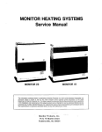
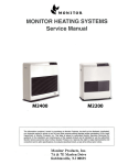
MONiTOR HEATING SYSTEMS
Service Manual
MONITOR422
MONITOR 2 2
MONITOR 21,
.
MONITOR 441
MONITOR 41
MONITOR 40
MONITOR HEATING SYSTEMS
Section 2: Installation
I 1X.
OD cobper Tubing
I
NOTE: Fuel tank musr be a minimum 3 feet away from flue pipe.
MONITOR HEATING SYSTEMS
Section 3: Operation
- Circulation Fan Output : 388 cubic feet:min.
- Fuel source : Remote, separate tank
3-1 INTRODUCTION
Monitor is an easy-t~operate vented kerosene
heater. Routine operation features high BTU output.
automatic adjustment of room temperature, low fuel
and power consumption, and choice of automatic or
manual heater operation.
- Potential heating area : 900-3200 sq. feet
'The energy from the combustion process IS
released in the form of heat and vaporized water.
Normally. heating systems discharge water from
combustion to the atmosphere without condensing
it. This 93% efficiency rating means that. assuming
the water cannot be condensed, 93% of the heat
produced by the combustion process is recovered.
Assuming the water can be condensed, the efficiency is 87%.
This section provides all information necessary to
operate the Monitor Heating System. All operation
procedures specified should be performed in the
order in which they are described.
3-2OPERATING SPECIFICATIONS
The following specifications apply to the operation
of the Monitor 441 and the Monitor 422.
NOTE:
Monitor 441
Rated Efficiency (as applied to kerosene
heaters): 93%'
Rated Efficiency (as applied to central heating
systems): 87%
Power Consumption : as follows
-
HlGH
Actual effective heatirig area depends upon
numerous factors such as type and severii
of climate, type of dwelling construction,
condition of dwelling, and thickness and
effectiveness of dwelling insulation.
Table 3 1 lists Monitor 641 performance specifications at various user-selected heat output settings.
MEDlUMHlGH MWUMLOW LOW
IGNITION BUR4
BURN
340watts 65watls matts
BURN
58-
BUFIN
58wam
Table 3-1 HEATER PERFORNlANCE SPEUFlCATlONS
Ssthng
Specification
I
Rating
Heater Output/hr.
I
16,200
I
15.000
I
Medium
Medium
Low
Low
I
ZI,MX)
I,
19.W
I
High
High
1
33.900
I
3.500
I
I
43.cm
1
40.0OO
I
0.12
0.16
,025
0.39
&hrs/day burntime (5-gal. tank)
52days
3.9days
25daP
2.WaYs
Bhrs/day burntime (55gal.tank)
57.3days
27.5days
2Y.Mays
Continuous-use bumtime (55-gal.tank)
l9.ldays
14.3days
Q2days
72days
2BS.5days
214.fflays
137.5days
107.8days
955days
71.6days
45.8days
35.9days
Fuel Consum~tion(~al/hr)
1
Bhrs/day bumtirne (275-gal-tank)
Continuous-use bumtime (275-~al.tank)
43days
,
(
I
,
MONITOR HEATING SYSTEMS
Section 3: Operation
Monitor 422
Rated Efficiency (as applied t o kerosene
heater): 93%'
Rated Efficiency (asapplied to central heating
system):0?%
Power Consumption : as follows
-
-
lGmm
HIGH
BURN
- Circulation Fan Output : 176 cubic feet/min
- Fuel source : 1.32 U.S. gal., separate tank
- optional
Potentional heating area : 600-2000
sq. feet
Table 3 2 lists Monitor 422 pertormance specifications at various user-selected heat output set tin^.
MEDIUMHIGH MWUMLOW LOW
BlJW
BUFIN
BURN
5150watts
50watts
TaMe 3-2HEATER PERFORMANCE SPECIFICATIONS
Setting
Specification
Low
Med~urn
Low
Med~um
High
High
Rating
9,600
11,700
17,400
22,000
Heater Output/hr.
8,900
10.900
16200
20,400
Fuel Consumption (gal/hr)
0.07
0.09
0.13
0.164
Bhw/day bumtime ti32-gal. tank)
2.4days
1.Bdays
1.3days
1.OdayS
Continuous-use burntime (1.32-gaI.tank)
18.9hrs.
14.7hrs.
102hrs.
8.0hrs.
Bhrs/day bmtime (55-gal.tank)
982days
76.4days
52.9days
41.9days
Continuous-use burntime (55-gal.tank)
32.7days
25.5days
I7.6days
14.Ddays
NO=
Capsule tank cannot be used in Conneeticut and Massachusetls.
MONITOR HEATING SYSTEMS
Section 3: Operation,
3 3 OPERATING CONTROLS AND INDICATORS
Several controls and indicators are used to operate
the heater and to monitor its performance as follows:
Figure 3-1,INDICATORS
11 12 13 14 15
OPERATION
21
22
23
10
17
18
19
20
FIGURE AND lTEhtl NO
CONTROL OR INDICATOR
FUNCTlON
Figure 34,hem1
RUN Indicator Light
Light to indicate that power has been apllied
to heater.
Illuminates when operation ON/OFF pushbutton switch is pressed to position ON
Figure 3-1, hem2
AUTO Indicator Light
Lights when heater runs in automatic mode.
AUTO, RUN, and appropriate BURNER STATUS Indicators are illuminated simuttaneously
if heater is burnina.
Figure 31, Item3
ECONOMY PLUS
Indicator Light
Lights when heater runs in Economy Plus
mode.
Figure 3-1, hem4
Empty Indicator Light
In case af using the cartridge tank,when the
fuel is empty, EMPlY Indicator Light blinks.
This LigM is not provided with Monitor 441.
Figure 3-1. Item5
BURNER STATUS
indicator Lights
Light in accordance
lows:
H B a t w
High
Medium High
Medium Low
Low
with heat
output as fd-
Light Pattern
Bindicators-ON
6indicato+ON
4indic.N
Zndicators-ON
MONITOR HEATING SYSTEMS
Section 3: Operation
FIGURE
AND ITEM
-
NO
CONTROLOR INDICATOR
-
FUNCTION
- -
Figure 3-1, ttem6
TEMP-Indicator Light
Figure 3-1,Item7
AM Indicator Light
Figure 3-1. kern8
PM Indicator Light
Figure 3-1, hem9
Digital Display
Indicates SET and ROOM temperature when
heater is running, and indicates time when
heater is Off. .
Indicates time and temperature for automatlc
operation setting.
Figure 3-2, Item10
TIMER SELECTOR
The automatic function allows the programming of different temperatures for different
times of the day. Two, three or four settlngs
can be used.
push-button switch
Figure 3-2. Item11
CLOCK SET
Indicator Light
Lights when heater is running and ~ i ~ i & l
Window is showing the temperature.
Allows programming of current time when
illuminated.
NOTE: Prior to programming current time,
Digital Display shows 88:88.
IMPOKTAKT: Oncs c m t time has been
pmgrarnmed, press the SET
p t s h b b n switch within 60
#cond6.0themise do& dbp b y will mvsnt to previously
progtammed time, If any.
Figure 3-2.Item72
1st Indicator LgM
Allows programming of first automatic time
and temperature selection when illuminated.
When programmed, heater automatically operates at specified time and temperature 0.e. 6:
00 am., 70'F), if set for AUTO, providing that
heat81 has been .set for automatic mode of
operation.
TiME TEMP,HOWUP), MINEDOWN) and
SET push-button switches are used to prp
gram first operated time and temperature.
IMPORTAKI. Onca time and temperature
have bssn prograramsd, the
SET p u s M d b n mwttch must
be pres8ed with in %seeon&
Ohemisel time and tempera
ta will rWMt to pmviwsty
programmed time, Iany.
When this Light illuminates, 1st presently prct
grammed time and temperature displayed.
Figure 32,ttem73
2nd Indicator Light
of second automatic
time and temperature selection when illumiAllows programming
nated.
MONITOR HEATING SYSTEMS
Section 3: Operation
-
-~
FIGURE AND IEhA NO
CONTROL OR INDICATOR
-- -
Figure 3-2, ttemi4
3rd Indicator Light
Figure 32,ttem15
4th Indicator Light
FUNCTION
-
-
-
Programs 3rd automatic heater operation as
same as 1st Indicator Light.
Programs 4th automatic heater operation as
same as 1st Indicator Light.
TIME push-button
switch
This switch is used to set time and change
display over.
Figure 3-2,Item17
TEMP push-button
switch
This switch is used set temperature and
change display over, in 2 degree increments.
figure 32,Item18
HOUR/UP,
MINUTE/DOWN
repetitiveaction
push-button switch
Figure 3-2,Item16
.
Programs time or temperature.
NOTE: Each time push-button switch is
pressed, the digit advances in increments of one digit, If push-button is
pressed and held, the digits are
advanced repetitively.
Figure 3-2.Item19
SET push-button switch
'Sets' time and/or temperature.
If this control is not pressed after time and/or
temperature have been programmed, the time
and/or temperature programmed (as indicated
by display window) will not be accepted, and
will revert to previously programmedtime and/
w tempemre.
figure 32,Item20
CLEAR push-button switch
Erases any programmed time and temperature.
When cleared, time and/or temperature previously pmgrammed and displayed disappear@)
frwn window.
IMPORTANT: Both current time and automatically programmed
tims(s), tampamture(r) will
have to be reprogrammed tf
.kcblal operation is interrupted by power failure or by
dbcocmecting heater plug
fmm wall outlst beyond 5
mkurbss nthh otarrs, the
h t o r will go brto MANUAL
mode of opemtion and maintahrr#wntwnpsmtureacwfding to ttm setting bmperature
you've #leded by using the
Jide sdector for the rseet
tempemmatthekwarrigtlt
hand Jde ot ths cabinet
Figure 3-2,kern21
ON/OFF push-button
switch
ON position (push-button is 'in')applies power
to the unit. When this occurs, the RUN indicator lights to indicate that heater operation has
begun.
OFF position (push-button is 'our) remove
power fmm the heater. All circubexwpt for
Clock and Air Row
are shut down.
-
MONITOR HEATfNG SYSTEMS
Section 3: Operation
RGURE AND IT34 NO
CONTROL OR INDICATOR
FUNCTiON
Figure 3-2,Item22
AUTO push-button
switch
Places heater in automatic mode of operation.
AUTO indicator lights to confirm automatic
operation.
Assuming that the heater has been properly
programmed and heater is in ON position,
heater will operate automatically.
When pressed again, AUfO indicator goes out
and then heater will operate in MANUAL
mode. During rrianual operation, the user turns
heater ON and OR, at will.
When AVTO is disengaged, the unit will
operate om .a manual.temperature determined
by the AUTO setting for that time of day.
ECONOMY P U S
push-button switch
Places heater in Economy Plus mode of
operation. ECONOMY PLUS indicator lights
to confirm Economy Plus operation.
When pressed again, ECONOMY PLUS
indicator goes out and then Economy Plus
mode will be cancelled.
NOTE: Economy Plus mode is accepted only
in the MANUAL mode.
Figwe 3-2,item23
,
3 4 PRE-OPERATIONCHECK UST
After heater installation. but prior to Monitor heater
start-up, inspect the system for operational readiness. The following check list specifies those items
that should be inspected on a routine basis:
Check that the Monitor heater is plugged into
wall outlet
(I20 Vac, 60 Hz)
Verify that adequate supply of kerosene is
available in fuel tank
Confirm that fuel is free of water M Other
contaminants
Check fuel tank for good operating condition; it
must be free of rust, conosion, and/or leaks
inspect fuel Line for signs of leaks, loose
connections, cracks, air pockets or blockages
Confirm that Fuel Valves on Fuel Tank and
Fusible Link Valve are open so fuel can flow
freely
Outside dweliing, check area immediately
around Flue Pipe for combustibles or obstntctions to.free air circulation
Inspect Air Line for cracks, loose connections
or blockage
Check Exhaust Line for cracks, toose ComaCtions or blockage
~t rear of hater, verifythat air flaw to tk Air
Circulation Fan is not blocked
Inspect dwelling interior and confirm that immediate area near heater is free of combustible
and obtects that might interfere with free air
flow.
.r Make certain that Heat Sensor is not exposed
to drafts, direct sunlight, nor direct heat from
the Monitor.
.I
Confirm that heater is level
If this inspection reveals any system deficiencies,
correct the problems before operating the heater.
3-5 OPERATION
Operation of Monitor heater can be controlled
manually by the user, or run automatically'by the
microprocessor.
Paragraphs.3-6through 3-10 provide the details of
heater start-up, operation, and shutdown. The
controls and indicators illustrated by Figure 3-1 and
3-2 are used to operate the system and to monitor
the heater's performance.
MONITOR HEATING' SYSTEMS
Section 3: Operation
3-6MANUAL HEATER OPERATION
Operation of the heater is under the direct control of
the user (heater will not operate automatically),The
heater will, however, automatically respond to
changes in room temperature signaled by the Heat
Sensor to maintain the temperature of the room at a
comfortable level.
NOTE:
Resetting the Fuel Constant Level Valve is
necessary only if the heater is being started for the first time, hasn:t been used for an
extended period of time, or if tank has run
empty. If priming is unnecessary skip to
step 2.
m.
1. Decreasing electrical consumption by decreasing
the frequency of ignition cycles.
2. Reducing heat loss during the prepurge and
postpurge cycles.
3. Reducing inefficient combustion associated with
start up and shut down.
4. Prolonging component life by decreasing expan. sion and contruction of internal parts.
NOTE This feature could be compared to driving
Prime the Heater
Gently press and release the Fuel Constant Level
Valve Reset Lever four or five times.
'
STEPZ: Select Manual Operation
If heater operation is in AUTO mode, press the
AUTO push-button switch and change Auto to
Manual made.
IMPORTAW. In case no temperature is mat, tsmperature will automatically k n t at
the wtting temperature nlect.d by
using lhe slide selectot for the m8et
temperature.
Turn Monitor On
Press me 0N:OFF push button switch to position
ON. The RUN indicator light illuminates to indicate
that power has been applied to the instrument and
tte heater is cycled for manual mode of operation.
IbSlRCTlONS FOR ECONOMY PUlS MODE
To engage the economy plus mode. simply press
down !he button labeled
-nomy
P'rrs's to
disengage press again.
NOTE: Operation switch must
3-7 AUTOMATIC HEATER OPERATION
Automatic operation is established by programming
the time 'temperature settings for specific times. On
a daily basis, a maximum of four time -temperature
senlngs can be programmed.
If. subsequently, it should be desired to switch to
manual mode of operation, the changeover can be
made at any time.
Proceed with automatic mode of operation in the
following manner.
STEP3: Select Temperature Setting
Press the TEMP push-button switch and press
either the UP or DOWN push-button switch to set
me digital set room temperature indicator to the
desired temperature, and then press the SET pushbutton switch.
-4:
an automobile in stop and go traffic (regular
mode) versus highway driving with cruise
control engaged (Economy Plus mode).
be
'OW end in
STEPI:
Program Clock for C u m ! Time
A Press the nMER SELECTOR push-button
switch,at which time the CLOCK SET indicator
light will illuminate.
8. Press HOUR push-bunon switch to program
current hour on the Clock.
IMPORTANR Be wre to set clock tor AM or PM,
as appIopMld
NOTE Both hour and minute digits on Display
Window are advanced in in-mments of one
by pressing the a~pro~riate
push-button
switch one time for each digit; digits can
also be advanced repetitively by pressing
and holdlng the appropriate push-button
swim.
C. Press MINUTE push-button switch to program
the cunent minutets) on .Clock
D. immediately after programming cunent time in
t e r n of hours and minutes, press the SET
push-button switch.
MANUAL mode.
This feature minimizes the 'ON ' and ' O f f cycling
of the unit by allowing it to overshoot the set
temperature by 12 degrees instead of the n m l
4 degrees.
The advantages of this feature are to increase the'
overall efficiency ofthe unit by.
29
STEP2: Program the lst Time Temperature
A Pressing the TIMER SELECTOR push-button
switch will illuminate the 1st indicator light
8.
n m pust-+bunon switct~.
MONITOR HEATING SYSTEMS
Section 3: Operation
C. Press HOUR and MINUTE push-button
switches to program 1st desired time.
IMPORTAKT: Be sure to set the dock AM or PM,
as appropriate.
Immediately after programming the 1st desired
time. press the SET push-button switch. This
step must be completed within fifteen seconds
after programming the time.
E, Press TEMPpush-button switch.
F, Press UP and for DOWN push-button switch(es)
to program 1st desired temperature.
G, Immediately after programming the 1st desired
temperature. Pressthe SET push-button switch.
This step must be completed within fifteen
seconds after programming the temperature.
D.
STEP3:
Program the Remaining Times
By pressing the TIMER SELECSTOR push-button
switch again, the 2nd Indicator Light will illuminate,
at which time the 2nd setting can be programmed.
Press again to set 3rd and again to set 4th.
IMPORTAHT: The SET push-button swnch must be
pressed attar each setting b lock
into memory.
Should heater power be interruptad
by a power failure or by disconnsction
of h e power owd beyond 5 minutes,
heater roveris to MANUAL operation,
and all AVTO programming ts e
d
STEP4: Salad Automatic Operation
Press AUTO push-button switch. The AUTO indicator light will illuminate.
Turn Monitor ON
Press ON/push-button switch to position ON.
-5:
The RUN indicator light will illuminate to indicate
that power has been.applied to the heater.
F m this point, heater operation is as follow example.
S m : Reprogramming Current Time
(ifnecessary)
A. .Press the TIMER SELECTOR push-button
switch to illuminate the CLOCK SET indicator
light
8, Press HOUR and MINUTE push-button
switches to program new current time. Set
applicable time by watching Clock display.
C. Press SET push-button switch.
IMPORTANT: If SET push-button switch is not
pressed, wrrent time will revert to
previously programmed time.
STEP2: Reprogramming Automatic Operation
A.
8.
C.
D,
E,
F,
G,
H,
I.
Press the TIMER SELECTOR push-button switch
to illuminate the appropriate indicator light. (Ist,
2nd, 3rd, or 4th)
Press TIME push-button switch.
Press CLEAR push-button switch. Time displayed on window will disappear.
Using HOUR and MINUTE push-button
switches program new desired time by watching the Display Window.
Press SET push-button switch.
Press TEMP push-button switch.
Press CLEAR push-button switch. Set Temperature displayed on Window will disappear.
Using UP and DOWN push-button switches
program new desired temperature by watching
the Display Window.
Press SET pusbbutton switch.
3-9 HEAT SENSOR
Heat Sensor islocated on the rear of the cabinet. It
is recommended to leave the aensor in its original
mounted position. However should relocation be
necessary, choose a location for the sensor that is
not in the path of direct sunlight drafts or the flow of
w m air f m the heater. Loosen the screw and
release the sensor from the mar of the cabinet
Fasten the sensor to Zhe wall with the screw.
3-10 MONITOR SHVrOOWN
A simple one-step procedure Q utilized
the Monitor.
shutdown
Press ON/OFF push-button switch to position OFF,
the RUN indicator will extinpuish.
-ANT:
34 REPROGRAMMHG THE MONerOR HEATER
On occasion. it m y be ne-ry
to rf3PrOgm the
Monitor.
Remagramming is pertwmed as specified belaw:
Orrcs h a t e r has shut down, It annot bs rsrtarted until poa-putge eyda has been canpletd. If ONIOFF
switch is k R in posttion ON, Monttor
ommtiar will automatically resbrt
m-pie-
m
p
u
r
g
a
.
MONITOR HEATING' SYSTEMS
Section 3: Operation
3-TI ,OUT OF N E L
During either manual or automatic operation of
heater. fuel in the tank may be depleted.
,
The Monitor (in case of using external fuel tank) is
known to be out of fuel when all of the following
symptoms are present
- Burner Status indicator lights blink.
- Absence of flame (visually verified through view
plate on wall of Combustion Chamber).
m.Tum Heater OFF
Press ON/OR switch to O R .
STEP2: . Flll Fuel Tank
A,
5.
C,
.
D.
Close shut-off valve at outlet of ~ u eTank.
l
Drain Fuel Tank (from battom; if possible) to
remove all condensation, debris, and old fuel.
Fill Fuel Tank with fresh, crystal clear kerosene.
Upon completion of stepC. open shut-off valve
which was closed in stepA above.
STEP3: Turn Heater ON
Press ON!OFF switch to ON. Proceed with normal
heater operation.
The Monitor 422 (in case of using capsule .fuel tank)
is known to be out of fuel as follows:
When the E M P N indicator light illuminates
and flashes, a buaer will sound for twenty
seconds. The burner mode is changed to 'Low"
automatically, and Men, the heater will shut off
after 30 minutes.
The remaining burning time is indicated at the
Display Window.
Install the tank with the arrow pointing forward, and
close the tank cover.
STEPS: Turn.Heater ON
Press ON O f f switch to ON. Proceed with normal
heater operation.
342 RECOVERY FROM A POWER FAILURE
For the power intemption of up to 5 minutes, the
set memory is- kept and will resume operation
automatically with the set memory.
For power intemptions beyond 5 minutes, heater
will resume operation (after a 3 minutes cool down
period) in the MANUAL mode and maintain room
temperature according to the setting temperature
selected by ustng the SLIDE SELECTOR for the
reset temperature at the lower right hand side of
the Cabinet
When the TIME push-button switch is pressed or
the TIMER SElECTOR push-button switch is pressed
to illuminate the CLOCK SET indicator light, the
Display Wlndow will show 88:88 indicating the
need to reset the clock and re-program the heater
for automatic aperation.
REMAM In wrkr to dispby mmt temperature,
It .hould be wt before tfie heater is
plugged h and energized.
New rewt tsmpemtaire selected after
plugged kn will take effect only after a
powsr-
3-13 RECOVERY FROM OVERHEAT
The Monitor is protected against damage resulting
from an ovetrtteat condition by two 110'C (Monitor
422).nsc (Monitor441) automatic reset tfmnostats.
STEPk
h the event of an overneat the thennostats are
triggered to cut off the flow of kerosene to. the
B u m Pat. the flame is extinguished automatically,
condition by
a user is alerted to Fhe
blinkin0 of the Bumer Status indicatws.
STEP2. Utt Out the Capsuk Fuel Tank
To recover from an overheat condition.
diin@d below:
Refueling:
1urn Heater OFF
Press ONfOFF switch and wait 15 minutes for the
heater to tool.
--
Open the tank carer and lift out the capsule fuel
tank
Turn the tank upside down. and remove the fuel
.
Fill the Capsule Fod Tank
Fill the capsule fuel tank with fresh, c-1
kerosene by using a siphon.
as
STEPI: Turn OFF Heater
-2:
Allow Monitor H d e r
to cod
NOTE: Bewrettmtheaterbscodtotwch.
clear
M&I tht hpwk Fuel tank
Replace and tighten the fuel caD.To insure proper
fuel flaw, be sure the cap is secured
A period of 30 to 6minutes should be sufficient to
permit heater to cool completely.
-4:
unplug mbr
Disconnect heater power cad from wall outlet
Section 3: Operation
I
m P 4 : Cheek tor Cause of Overheating
STER
NOTE: Overheating is usually caused by objects
STEP2 Unplug h a t e r
that impede tree air circulation.
STEP3: Remove louver assembly
-4:
Look for debris and other obstructions a t front of
heater, at Circulation Fan a t rear of the heater, and
at Flue Pipe tip ourside dwelling.
STEPS: Remove Louver h m M y
m. ~ l & n eater bierior
Turn Monitor OFF
Remove front cover
NOTE As the ~ k n Cover
t
of the Monitor 441 is
connected-to the Printed Circuit Board by
Lead Wires, pljll the Front Cover to the front
side slightly and remove the Connector of
the Lead Wires from the Printed Circuit
Board, and then, remove the Front Cover.
STEP^ Locate and replace W
BEFORE PROCEEDING TO CLEAN HEATER, BE
SURE THAT HEATER INTERIOR IS COOL ENOUGH
TO TOUCH.
With a
clean, lint-free. damp rag or other appropriate
cleaning material, wipe up all dust dirt and debris
from exterior of cabinet, including exterior of Combustion Chamber and Heat Exchanger.
M ReplacsLouver Aswmbiy
STEP& Reeonnee! Monitor Heater P w e r Plug to
the Wail O'WL
STEP9 Turn Heater ON
STEPIO: Reprogram Heater Microprochswr
m
.Sdsct Mode of operation
C
A
m
I atter the camplolion of maww
pmcmdura, tht heater overheats
again, something hi wrong !
Do not operate heater Mtil Plobkm has been diagnosed and cor
rectsd
RECOVERY RlOM BLOWN NSE
All elechical components of the Monitor heater are
protected against pawer overloads and electrical
matfundions by two 2-p
fuses and a lGamp
fuse. Should fuse blow, the ~BCWW
Drocedm is
outlined below:
3-W
s )
STEP6: Reattach front cover
(In case of the Monitor 49% be sure that
'
the connector is wnnactsd to the printed
circuit board)
STEP7: Reattad louver assarnbiy
STEPB: Plug heater power w r d into wall outlet
-
m.Tum M m b r ON
STEPlO: Reprogram heater
mmm
Aut#natic
opemtion cycb
appliabi8)
S E P l 2 .SdectAutomatic operation (if appii
-1
M-422 OPERATION TIMING CHART
OPERATION SW
SENSOR SW
I
(
ROOM TEMP
SET TEMP
.-
/
I
FLAME
I
PHOTO TRIAC.
PHOTO COUPLER
L E D INDICATOR
i b ' I
I
BUZZER
-
l
l
MONITOR HEATBNG SYSTEMS
Section 4: Maintenance
cally in order to sustain the efficiency of the Moniroi
Heating Systems.
4-1 INTRODUCTION
Heater maintenance is divided into two classifications; periodic maintenance ISrequired to maintain
the heater In good OPerating condition; co~ective
maintenance is necessary to repair a malfunction.
~t ~e tirne of h e demonstration or installation,
heater maintenance should be discussed with the
user; emphasize that a clean heater and proper fuel
are the keys to opt~murnheater operation' and
performance.
4-2 PERIODIC MAINTENANCE
The Maintenance Schedule provided in Table 4-1
describes the tasks that must be performed periodi-
Table 4-1 SUGGESTED MAINTENANCE AGTlVmES
Activity
Material
Remarks
Check all fuel pipes for leaks and
loose connections
3.18"OD copper tublng
Fuel piping must be secure and
free of leaks, Replace tublng
when necessary.
lnspect exhaust piping for leaks or
loose connections
All exhaust pioes must be covered
by a cloth insulation cover.
If cloth cover shows signs of
discoloration at joints, check
brings.
Check fuel for water and/or other
contamination.
Ifthe capsule rank is used on the
Monitor 422 the capsule tank filter
should be checked, cleaned or
replaced, as well as the constant
level valve strainer.
Fuel color should be crystal clear.
if fuel is contaminated, see Corrective Maintenance procedure,
paragraph 4-9,
lnspect Fuel Pipe for obstruction
lnspect electrical wiring for
cracks, signs of deterioration, bare
wlres and/or loose connectors
Clean heater
UNPUlG HEATER BEFORE PRQ
CEEMNG. HEATER MUST ALSO
BE COOL BEFORE STARTING.
Clean, lint-free cloth and a mild
non-abrasive household cleaning
agent. USE ONLY NONPETROLEUM D I S T I L L A T E
CLEANERS.
Wipe down exterior of heater cabinet. Vacuum heater interior (if
necessary).
Clean Air Circulation Fan (Monthly)
Vacuum fan cage. Wipe fan
blades.
Inspect as piplng for leaks or loose
connections.
lnspect rubber Air Hose at rear of
heater.
Look for cracks, wear, or signs of
deterioration; replace if necessary.
Clean fuel constant level Valve
filter. Inspect fusible link Valve
input fitting.
Clean only if necessary. Verify that
heater is level.
Clean Kerosene
Refer to paragraph 4-5. Procedure
is described in paragraph 4-6.
Check Leveling Guide.
i
ff blocked, clean and vacuum.
If corroded badly, replace.
inspect flue .pipe for obstruction
or corrosion.
35
MONITOR HEATING SYSTEMS
Section 4: Maintenance
Activity
Material
Remarks
Inspect Combust~onR ~ n g ,Flame
Sensor Rod, Baffle, and Burner
Cloth.(Suggested frequency every
3 years).
Clean all carbon dewsrts. Replace
if excess~vely worn, warped, or
cracked.
NOTE If any gaskets are tom
when Components are
removed, the gasket must
be replaced.
Clean Combustion Chamber (every
3 years)
Vacuum all carbon deposrts from
interior of chamber.
Inspect air holes in Burner Pot
Use a small, stiff brush or a short
length of sott copper wire to clean
any blocked holes.
The M422 may need alr holes
reamed with a torchtrp cleaner if
partially block on a 5 to 7 year
basis.
Clean Igniter
Scrape any carbon deposits from
igniter..
Check air piping that interconnect
Combustion Blower and Air Pressure Switch.
Replace air piping that is worn,
broken or brittle.
Check for carbon build up in fuel
inlet going into bum chamber (every
year)
Disconnect copper fuel piping from
bum chamber and clear fuel inlet
line by reaming with a solid piece of
coat hanger) which should be able
to go in approximately 3" without
obstruction.
NOTE: Removing ano retightening
burner fuel connection
must be done when the
burner cools down c m pletely. H it is done when
the bumer is hot, the welding on me fuel joint may
break. Fixing torgue for
nut;30-40kg = c m ( 2 6
4-3 INSPECT EXHAUST/AIR PlPlNG
Verify that all exhaust and air pipes are free of leaks
and loose connections, as specified below:
securely, espec~allyat joints.
C. Turn heater ON.
D. Carefully apply a small amount of soapy water
(with a paint brush) to the sudace areas of the
airlextraust piping.
Remove Rotedive Cloth
S ) all exhaust
Remove ~10thinsulation C O V ~ ~from
pipes.
.
STEP2: inspection of Exhaust/Air Piping
STEPS: Return to Operating CondKon
A.
heater
A.
B.
Visually inspect both air and exhaust piping for
obvious cracks, Leaks, or loose connections.
Black
mn
may be evidence Of
these leaks, and' o-rings may need to be
replaced.
Be sure that all pipes are installed tightly and
B.
leaks mat may exist will be readily
identified by the appearance of bubbles.
Dry all pipes with paper towels.
C. Repair any leaks that have been found (if
D.
36
necessary, replace the tubing).
Replace cloth insulation coven.
MQNlTQR HEATING SYSTEMS
Section 4:Maintenance
4 4 VERIFY I G N E R OPERATION
Visually inspect Igniter Operation
HEATER IS OPERATIONAL DURING THIS INSPECTION. AVOID DIRECT CONTACT WITH ANY
HEATED OR ELECTRICAL COMPONENT.
STEP1, prepare' for Inspection
Remove Louver Assembly.
CLOSE FUSIBLE UNK VALVE ON M 4 2 2 OR CLOSE
SHLJT-OFF VALVE OF THE EXTERNAL FUEL TANK
ON M-441 TO AVOID DRAINING AlL NU,FROM
TANKS.
NOTE:
5,
C.
Disassernbiy
STEW:
A.
STEP2:
A.
Power should be O R during the performance of this procedure.
Visual Inspection
Turn heater ON.
Look (downward) through window on the Corn:
bustionchamber. Verity that igniter is glowing.
Using a phillips head screwdriver, unscrew the
screws holding the rounded diamond-shaped
cover plate at the bottom of the Fuel Constant
Level Valve. Remove the cover plate.
NOTE:
If igniter does not glow, something is wrong.
Refer to the Troubleshooting Chart in Section 6
of this Service Manual to diagnose the problem.
An alternate inspection i s to feel the igniter
cover after the unit has been in the ignition
stage for about 5 minutes. It should be warm.
B.
Position a six inch U shaped piece of metal
or cardboard under strainer cover to drain
fuel into a pan.
Carefully remove the rubber gasket which is
located behind the cover plate.
STEPP: Inspection and Cleaning
A.
Pull the filter straight out of the fuel reservoir.
If the filter is dirty (but undamaged), rinse the
filter in fresh, clean kerosene to remove all
particles. Replace damaged filters.
C. To drain off upper m i o n of fuel constant level
valve, back out phillips head screw which is
located slightly above and to the left of filter
cover plate. (See Fig411
D. If upper portion drain is dirty or containing
water. then remove pump and inspect and
clean its screen.
B,
CAUTION: If igniter is broken,do not operate the
'ON /OFF switch button repeatedly.
STEPS: Reassembly of Heater
Turn the heater O R and replace the Louver Assembly.
4-5 CLEAN NU.CONSTANT LEVEL VALVE FIL-
TER
Contaminants are trapped by the filter to prevent
them from clogging the Fuel Constant Level Valve.
The filter, itself has a great number of small pares.
Whenever a filter is tom or disfigured (enlarged
pores), it should immediately be replaced.
Inspect and clean the filter as indicated by the
procedure below:
STEPS:
Reassembly
Push the (new or cleaned) filter back into the
bottom of the fuel reservoir.
8, Replace both the,rubber gasket and the cover
plate. flake .care to properly align the screw
holes in the gasket and cwer plate).
C. Wipe up any spilled fuel.
A,
I
DNn Gudc Carm~ner
!
Dram Guide
I
M-441
Figure 6 4 CLEAN FUEL CONSTANT mEL
&tnlner
M-422
VALVE
MONITOR HEATING SYSTEMS
Section 4: Maintenance
4-6 CLEANING NSIBLE UNK VALVE INTAKE FISTING ON M422
At periodic intervals, the fitting on the Fusible Link
Valve should be cleaned to prevent any accumulation of foreign materials from clogging the inlet. This
is accomplished as follows:
UNPLUG THE HEATER. POWER TO THE HEATER
SHOULD BE OFF DURING THE PERFORMANCEOF
THIS PROCEDURE.
STEP(: Close off Fuel Supply
A. Shut off fuel at the Storage Tank or remove fuel
from the fuel sump tank with siphon and syrlnge
if using the capsule fuel tank.
B. Manually turn handle to close Fusible Link
Valve.
NOTE: Place paper towels underneath the Fusible
Link Valve to catch any spilled fuel.
STEP2: Clean Valve
A.
Loosen hex nut on Fusible Link Valve inlet
fittlng at rear of me heater. Disconnect the
copper tub~ngwhich delivers the fuel from the
storage or the fuel sump tank.
B. Using a small, straight piece of wire carefully
and slowly ream-out the inlet fitting on the
Fusible Link Valve.
Avoid scratching the inside wall of the fitting.
With a cotton swab, wipe the interior area of the
inlet fitting.
STEP3: Reconnect Fuel Line
A. Reconnect the copper tub~ngto the intake
fitting and tlghten the hex nut.
B. Turn ON fuel at Fusible Link Valve and at
storage tank or fuel sump tank.
C. Check for leaks.
STEPP: Installation of New Fuse
A, Install a new fuse into the fuseholder. The fuse
must be a 2WV, 2 amp or a 250-V, 10 amp type
as marked on the printed circuit board.
Do not use oversized fuses.
8. Reptace the Front Cover and the Louver
Assembly and plug the heater into the wall
outlet.
IMPORTRNT: Whenever the heater is unplugged,
the.Microprocessor must be repro.
srammed
when Dower is restored.
4-9 FUEL CONTAMINATION
Fuel, contamination is often difficult to diagnose,
even though it will adversely affect heater operation
and performance. The best course of action to take
when fuel contamination is suspected is to examine
all of the system's fuel filters, beginning with the fuel
storage tank. If a Monitor Kerosene Lifter is part of
me fueling system, examine and clean that unit's
filter, as well as the filter located in the Fuel Constant Level Valve. When it has been determined that
water or some other contaminants have infiltrated
the fuel, the following action must be taken:
BEFORE
PROCEEDING FURTHER, UNPLUG THE
HEATER
STEPI: Remove Contarninetion
A, Shut O f f the fuel supply at the storage tank or
at the Fusible Link Valve.
B. Drain off the contaminants from the fuel storage
tank or the fuel sump tank(M-422). Fill with
fresh, clean fuel.
SIEP2: Clsan the
A.
Clean fuel constant level valve filter and filter
compartment.
B. Remove the Louver Assembly and Solenold
Bump on the constant level valve. Clean the
Solenoid Pump filter.
SIEP3: Reinstall Cleaned Components
A. Rep1ace the cmmnts
coKect'y and lnstall
new gasket.
B. Turn on the fuel at the storage tank and at the
fusible llnk valve, and apply power to the heater.
If problem still exists and contammated fuel IS
suspected it can be checked by
A. Shutting off the fuel supply at the storage tank
and at the fusible llnk valve.
B. Drain off fuel at constant level valve.
C. Dcconnect fuel ltne at back of heater and hook
up a 5 gallon qu~cktank w ~ t hwoven good fuel.
D. Test run heater to see if problem clears up wrth
use of new fuel.
4-7 CORRECTIVE MAINTENANCE
The two procedures below are remed~esfor very
generalized types of operating difficult~es.
4-8 REPLACEMEM OF N S E S
A short circuit or s~milarelectrical malfunction could
cause the fuse to blow. Troubleshoot the cause of
the blown fuse.
Replace the fuse as follows:
DO NOT REPUCE N S E WHILE POWER 8 ON.
STEP(:
Removal of Fuse
A. Unplug heater. Remove LOWer Assembly and
Front Cover.
8. Remove the fuse from fuseholder on the Printed
Circuit Board.
I
38
-qQ+++
MONITOR HEATING SYSTEMS
Section
Servicing
5-1 INTRODUCTlON
Sewicing is required when the Monitor Heater is not
running at proper efficiency. This section covers
possible causes and corrective procedures for efficiency loses.
Signs of improper heater efficiency and performance
would be:
Yellowish lazy.flame
- Smoke from flue pipe exhaust
- Heavy soot and carbon build up in combustion
chamber
- Lowered heat output.
-
5-2 MEASUREMENT OF FUEL FLOW RATE
Fuel flow rates are preset and sealed. These rates
should not and we recommend they do not be
readjusted.
5-3 REMOVAL OF WATER DEPOSITS AND
CONTAMINANTS FROM FUEL CONSTANT
LEVEL VALVE AND FUEL UNES
NOTE: Disconnect the Monitor from power supply
(unplug) before proceeding.
Use a syphon pump and a syringe to drain off
any fuel in the fuel sump (in case of capsule
tank use on the Monitor 422).
2. Ifusing separate tank on the Monitor 422 shut
of! fusible link valve. On the Monitor 441 shut
off valve of separate tank.
3. Bend a piece of sheet metal or cardboard into a
U shape and place it under the fuel constant
level valve strainer cover to drain bad fuel into
a 1-2 liter pan. (Figure 4-1)
A, Remove strainer cover and drain.
8, With strainer cover removed, inspect, clean
and/or replace strainer if damaged.
C. Remove drain port screw and drain.
D. Replace strainer, cover and screw.
E. Open fusible link valve or shut-off valve to
refill system with fresh crystal clear kerosene.
F, Repeat steps 1-3 until all COntami~tedfuel
is drained off.
4. Remove fuel feed pipe from bumer pot and
solenoid pump, and drain fuel into pan.
5. Once lines are clear, reconnect fuel feed pipe,
turn operation switch ON and start a test run.
1.
NOTE:
Remwing and retightening bumer fuel
connection must be done when a bumer
cools down completely. If it is done when a
bumer is hot. the welding on the fuel joint
may break. Fixing Torque for nut30
-40kg crn(26-351b.in).
.
5 4 CLEANING THE BURN CHAMBER & BURNER
POT
Under normal running conditions, soot will not
deposit in great quantities inside the burner, and a
light covering of soot will not affect the performance
of the unit thus it.need not be cleaned. However, if
heavy soat built up does occur the unit should be
opened and cleaned.
The bumer is assembled using gaskets to maintain
its air tightness. If these gaskets leak. the extra alr
can cause a serious soot problem and or exhaust
gases to escape into the area being heated.
NOTE: If any gaskets are tom when commnents
are removed, replace. Disconnect power
supply to unit.
If cleaning is necessary, use the following method
On the Monitor 422
A. Remove lower assembly.
8. Remove front cover.
C. Remove top cover and lead wire connectors.
D. Remove front and top heat shields that
cover the bum chamber and their lead
connectors.
E. Remove fuel piping from bum chamber.
F. Remove igniter.
G. Remove flame detective rod lead from PCB
(DO NOT REMOVE fROM BURN CHAMBER).
H. Remove screw at top of bumer cap which
attached it to cabinet. Remove screw at
back of cabinet from exhaust duct and
remove the 4 screws holding the bum
chamber to base.
I. Rock chamber back and forth lightly, raise
about 1/2' and remove bum chamber and
heat exchanger, as one assembly from unit.
J. Set chamber upside down and remove the
4 screws which secure the bumer pot to
the bum chamber. Pull the bumer pot up and
out.
2. On the Monitor 441
A. Remove louver assembly.
8. Remove front cover and wire connecto~.
C. Remove top cover.
D. Remove heat shield that covers combustion
chamber.
E. Remwe service panel.
F. Remove Fbame detector rod.
For a more thorough cleaning, use the same
procedure as for the W22 above.
1.
MONITOR HEATING SYSTEMS
Section 5: Servicing
3. Turn counter-clockwise to remove combustion
ring. If ring does not turn, pull up slightly to
loosen retaining clips.
4. Use wire brush to clean inside of combustion
chamber.
Vacuum and wipe clean with a waste cloth.
5. If tar is present on the bumer bottom, remove
the tar by using a flat-bladed screw driver or
wire brush.then clean the area by using a
vacuum cleaner etc.
NOTE: Make sure all air inlet openings are clear.
6.
1
When cleaning the inside of me bumer pot,
remove the igniter and change the burner cloth
by the following procebure.
Nozzle Collar
Figure 5-3
Rgure 5 4
C. Apply glue at all 4 corners of Burner Cloth
as Shown in Figure 5-5.
7. On the Monitor 422
Awroa. 318
Apply glue(P/Na&lT)
on the burner bottom
as shown in Figure5-1.
A.
u
Figure 5-1
B. Put the burner cloth on the burner bottom,
8.
afterwards press and straighten out the
burner cloth so that it is glued flat and even
on the burner bottom.
On the Monitor 44l
A. Apply glue arround the burner cloth as
shown in Figure 5-2.
NOTE:
The Burner Cloth is not symmetrical in
shape, therefore make sure to place it in
the correct position so that the wider side
of the cloth is at lett side of the lgniter
Shield as shown in Figure 5 5 .
1 [jy-'m
Combustion ring may deform and deteriorate
after several years we and should be cleaned
and inspected before reinstallation. If combustion ring is warped, has cracked or is detenorating excessively it should be replaced.
10. When reassembling the unit check that combustion ring is positioned with the correct side
up and is sitting squarely on all three support
s c r e w s ( ~ 2 2or
) pins(Ni-441) inside the bumer
Pot.
11. Reassemble by reversing the procedure followed during disassembly.
9.
I
\
Oue
b
*OePl 'Is-
B.
NOTE:
.--___..'
Ftgure 5-2
As shown in Figure 5-3 and 5-4, insert the
Burner Cloth narrow between the Nozzle
Collar and the Igniter Shield, then push the
Bumer Cloth, using your fingers or a screw
driver, so that it slips in under the Naule
Collar. Afrerwards press and straighten out
the Bumer cloth so that it is glued fiat and
even on the Burner battom.
in some m e s , pulling out the Fuel Nozzle
and Collar may make this procedure easier.
An easy out can be inserted into nozzle to
hetp break loose and remove it.
40
NOTE: Use of the economy plus feature can
minimize service calls and extend cornponent life.
)I
MONITOR HEATlNG SYSTEMS
Section 5: Servicing
NOTE:
Make sure the position of flame detector rod is centered between combustion ring and bumer pot
before reassernbiing.(See Figure 5-6)
Flame Detector Rod
I
Combustion Ring Assy
\
Combustion
Chamber
Gap
M-441: 4mm (0.16) or more
M-422:3mm (0.12') or more
Burner
Pot
II
11
'
For minor adjustments of flame detector rod without
disassembling any components:
1.
Loosen the two retaining screws about half to
one full turn.
2. Tightening down on the top screw first will
cock the rod outward away from the combustion
ring. Tightening the bottom screw first will
cock the rod inward towards the combustion
ring.
5-5 CLEANING THE FUEL INLET
When cleaning the combustion chamber and the
bumer pot, the fuel inlet nozzle should also be
cleaned. This can be done as follows:
1,
Disconnect copper fuel line at bum chamber.
2,
3,
Push a piece of wire (about the same size as
the I.D. of fuel inlet pipe) into the fuel inlet
nozzle.
If obstruction is felt twist wire back and forth (to
brake up soot and carbon) so that wire ultimately penetrates igniter shield.
On M422, also check air holes surrounding
fuel inlet for blockage and clear if necessary.
MONITOR HEATING SYSTEMS
Section 6: Troubleshooting
Monitor 422/441 Resistance values
APPROX.
M-422
OHMS
M a 1
Igniter (connector B/B)
16.8
12.7
Power Transformer - Primary (AC 120V)
125
125
Power Transformer Secondary (AC 12V)
-
1.6
1.6
-
M7
647
4.600
4.600
63
W
235
115
247.5
258.5
Combustion Blower (M-422:BK 8 BK, M-M1:WH B GR)
22
78
Combustion Blower(M41:GR B OR)
-
92
COMPONENT
Power Transformer Secondary (AC 120V)
Damper Solenoid (connector 1/1)
Resistor (connector G/G)
Circulation Fan (M-422:RD 8 BK, M41:WH 8 BK)
Circulation Fan (M-422:BK B Y L M-441:BK & EL)
Thermistor (connector O/Q, at 7 7 F)
10,000
10.000
Fuse 2A (read with fuse out)
0.1
0.1
Fuse 10A (read with fuse out)
0.01
0.01
Solenoid Pump (coil)
565
565
MSCONNECT HEATER FROM POWER SOURCE
BEFORE MAKING ANY RESSTANCE VESTS.
MONITOR HEATING SYSTEMS
Section 6: Troubleshooting
Monitor 22 41 Resistance values
COMPONENT
APPROX.
M-22
OHMS
16.8
12.7
B)
Igniter (connector B
Power Transformer - Prirnav (connector H ti)
M-41
97
97
-
Power Tracsformer - Secondav (connector L L)
824
824
1.3
1.3
4,600
3.600
68
91
310
120
C~rculat~on
Fan (M-41:WH & GR, M-22:RD 8 YL)
365
190
C~rculat~on
Fan (M-41:BL & BK. M-22:GR & BK)
270
Power Transformer - Secondary (connector M M)
Damper Solenoid (connector I I)
Resistor [connector G G)
Circulation Fan (M-41:WH & BK, M-22:RD & BK)
-
-
-
C~rculationFan (M-41:BL & GR. M-22:GR & YL)
-
-
-
-
'
260
210
200
22
78
-
Combustion Blower (M-41:WH S GR. M-22:BK & BKI
-
Combustion Blower (M-41:GR 8 OR)
92
10.000
10,000
0.1
0.1
Fuse I D A (read w ~ t hfuse out)
0 .O1
0.01
Solenoid Pump ( c o ~ l )
688
695
Thermistor (connector Q Q, at 77
Fj
Fuse 2A (read with fuss out)
-
-
DISCONNECT HEATER FROM POWER SOURCE
BEFORE MAKING ANY RESISTANCE TESTS.
-
MONITOR HEATING SYSTEMS
Section 6:Troubleshooting
Monitor 4221441 Component Voltage Readings
READING TAKEN AT
COMPONENT
Thermistor
AC
DC
Q on PCB Sensor disconnected
5
-- -
Thermistor
Q on PCB Sensor connected
Air Pressure Switch,'
Overheat Protector Closed
Connector J
110
Air Pressure Switch,'
Overheat Protector Open
Connector J
0
Damper Solenold
I on PCB
Solenoid Pump
K on PCB
C~rculat~on
Fan High Speed
RD to BK(M-422)
WH to BK(M-441)
110
110
Circulation Fan Low Speed
RD to BK(M-422)
WH to BK(M-441)
93
Igniter
B on PCB
110
Power Transformer
AC 120V
110
Power Transformer
(secondary s~de)
AC 120V
AC 12V
120
12
Combustion Blower
High Speed
Combust~onBlower
Low Speed
Res~stor
F on PCB
110
1.53.2
105
pulse'
9
l
(primary side)
F on PCB
(Ql is Off)
921M-422)
~~(~-441)
G on PCB
1WM-422)
22(M41)
*Pulse can only be measured with a hlgh impedance d~gltalvolt meter.
I
MONITOR HEATING SYSTEMS
Section 6: Troubleshooting
Monitor 22 ,'41Component Voltage Readings
COMPONENT
READING TAKEN AT
Thermistor
0 on PCB Sensor disconnec:ic
Thermistor
0 on PCB Sensor connect&
Air Pressure Switch
Overheat Protector Closed
Connector J
110
Air Pressure Switch
Overheat Prctector Ooen
Connector J
0
Damper Solenoid
l on PCB
-
AC
DC
5
1 .E-2.3
105
-
Solencld Pump
K on PCB
105
C~rculationFan H ~ g hSpeed
GFi to BK BK to RD lM-21)
BL to BK BK to WH (M-4C1
110
110
C~rculatlonFan Low Speed
YL to RD GR to YL IM-21)
GR to WH BL to GR IM-40)
110
110
lgn~ter
B on PCB
110
Power Transformer
(primary side)
H on PCB
110
Power Transformer
(secondary side)
Connector L
Connector M
120
Combost~onBlower
High Soeed
F on PCB
110
Comcust~onBlower
Low Soeed
F on PCB
(RL3 is OFF)
P2fFvl-221
88(M-41)
Resistcr
G on PCB
18tM-22)
221 M -311
11
TEST POINT VOLTAGE
Preparallon
Pre-purge
Pre-heal
lgnillng
Pre-burning 1
low med 2 mln.
(C.F.M:W
Prebumlng 2
(C.F.M:Low)
TP 2
5 V i 10%
5V f 10%
5V f 10%
5 V f 10Yo
5V f 10%
TP 3
12V If:30%
12V f 30%
12V f 30%
12V f 30%
12V f 30%
TP 4
1.5-3 2V
1.5-3 2V
1.5-3.2V
1.5-3.2V
1.5-3.2v
TP 5
pulse
pulse
pulse
pulse
pulse
1.2V mifl.
1.2V min.
5W
5v
Mode
TP 6
ov
ov
lnflnitly
variable
TP 7
pulse at
plugin
5V
5V
~igh
Medium-High
Medium-Low
Low
OFF
Posl-purge
Waillng unlil
pragrammed Lime
comes on'
TP 2
5V f 10%
5V k 10%
5 V f 10%
5V f 10%
5 V f 10%
5W f 10%
5V f 1 0 1
TP 3
12V f 30%
12V f 30%
12V f 30%
12V f 30%
12V f 30%
12Vf 30°/o
12V f 30%
TP 4
1.5 -3.2V
1.5-3.2V
1.5-3.2V
1.5 - 3.2V
1.5-3.2V
1.5-3.2V
1.5- 3.2V
TP 5
pulse
pulse
pulse
pulse
pulse
pulse
pulse
TP 6
1.2V min.
1.2V min.
1.2V min.
1.2V min.
OV
lnfinitly
variable
OW
TP 7
5V
5V
5V
5V
5V
5V
5V
d
-
m
m
ul
n
rd
4
o
--
,L
. 5P
5
J
f
ce,
5
n
$
.
(Pa
c 93 . 1 c -a q-
d
Q
,
/
5n i5'i
'
'
,
E
w
-
'
<
/
,
2
2 2
d
5
c I3 . I C q q
0
0 ; s
L "b < ~
E , ._ <
d
U l c r . < <c
1 . g 2 a g
?
5
--
m
-W +W +Q +Q +Q + Q +
-.
-0
0
2
2
MONITOR HEATING SYSTEMS
Section 6: Troubleshooting
MONITOR HEATING SYSTEMS
Section 6: Troubleshooting
lNDlCATlON OF FAILURE MODE
- ----- - - - Trouble Point
Digital Display
The Reason of Indication
/ /
At pre-purge, Flame rod is sensing flame
Flame senslng clrcult grounded
when there should be none.
flame rod or p~nchedwlre
/
C
/
L/ /
1 1 1
7
L
-
L/
I/
-
After power on, power supply to the micro- Timer clock circuit bad or power
r/
processer timing circuit is incorrect.
.
source to unlt above or below
acceptable levels.
/-
At starting of operation; the circuit to drive
Solenoid Pump control circuit
Relay RL6 of Solenoid Pump is mal-
has a malfunction.
functioning.
:
:
I-
,'-
'-
r
I
' I1
-
'-
1
When unit is shut off either manually or
Driving circuit of RL6 or excess
I
j automatically, flame rod does not detect fuel in burner pot.
I
'
flame out within 300 seconds.
NOSW3t.i
cpalarrol pue passer 1aro1 l a s anten p r o 1 l u e l s u q l a n j c e ~
.uwo arler rue1 .yuet UI Ian1 s(
cPaddols ue j uotceInan9 sen
'ES BB srror(s moputr*
l e l d s # a ~(uolldnnalul
dallno llev ul
ramod
pauasul
e u Bnld
a ~ getaql
r a ~ re"
o dsl
REASON
1 I
CORRECTIVE MEASURE
able 10 change
mrpln(lC121.
Failw 01 TR anay
llcM
R e o l ~ Sdolsrmd
s
punD
I
W a c s cidahon
Isr mta.
I
Failw ol mnbrnlim
Max crrrhaum
blm:
blaa
I
ctmmct lmn ,*sir
la a1 O pins. and
Ma. ul t s m r r l u r a
llDn Lar Io Hbh.
1s circulal~anIan
malot able to
change w e d 7
I
Failua 01 citmlalfim
Ian mla
Fdlua a( phrro mac
Fail-
I
-
9
-
PI biec
-
I
Fsilus d resirta la
-1irn~m-a.
Failua 01 darpa
sdemid.
Failua ol camcitr,
Icill.
Failua ol mi-
M a c a daroer
Jdemid
I
I
REASON
R e ~ l a c nIranrlmma,
I t mas nK.9
than t 3Vdc .I
rPs 7
w
I
02Yh u lau
.I OT.
Failme ol diode
lDIW
1
FUME ROO B Y P A S ClRCUll
F a lalN puporn 6 fh
&l.cla md b w u ckcuil
~
can k mods
M. caairtinp d 2 hwblsd 8lip.m clip¶. 2-0- ~ i n c 04
~ sinaubled
S
I-114- wm ua w t ~d i d . and 1-114- wan ~ m OHM
k
rssbla.
fhacrmp~mnbmm(ob.~dlopm~hreguenc*u.homh
d'wmb o k Iml* crmponM S U I ud
~ po)uWl.
(lum h a m ctcuil b mn& Ih. unit ij
bmsd 4 h m d i t d y nnm )Ir p.prg. p . h s a ~w l s ; *hen mod. liiht
q Ihd 0 D tl Hma dimowclod OH Ih. PCB and rspbced
c b m Th mil lhould I h n cmlinw tunclkminp u
with Um
-
-
--
Failua ol * i t i t q l
a
n-
Cored
win-
d(pard.
Cored imQIbMn
I
1
I
1
CORRECTIVE MEASURE
-
Curlain or other obslruclion
covers clrculalion air Inlel.
Is window
curlain loo
close to Ihe
rear of unil?
Is Circulelion
Fan Guard
dusly7
REASON
I
I
Cleen guard.
Keep curtain ltom unit.
C
.
Obalecfe covers clrculelln~
air oullet.
properly7
Remove obstacle.
h
Replace or check P.C B
Failure ol P.C.6
Circulalion Ian leilad.
-
Replace Fan Molor.
Repair or replace wiring.
CONNECTION OF LEAD WIRES
nrlI3
OPERATION TIMER SELECTOR
OODOO
n
TIMED
TEMP D
TIMEfEMP SET
Panel Printed Wiring board
ECmDMY
BURNER STANS fEMP Sm R O N
RUN AUTO PLUS
D
i
n
Lamp Pr~ntedWiring Board
Main Printed
Wiring Board
Pressure
Switch
Semor (Thermistor)
Over lieat
Thermostat
Slide Switch
Solenoid Valve
+
Ground
Power
ma
Blower for
Combustion
Resistor
Blower for
Clrculat~on
Fan
Thermostat
figure 7-1 MonitorU
Juncl~onBox
MONITOR HEATiNG SYSTEMS
Section 7:Electrical System
Printed Circuit Wiring Diagram
CONNECTION OF LEAD WIRES
-h
,
,
,
,
r1,
,
11
OPERATION TIMER SELECTOR
=ODD,
D
TIMED
TEMP0
TIMWtMP SEl
Panel Printed Wiring Board
RUN A ECONOMY
~ PLUS
D EMPTY BURNER STATUS TEMP SET
m
0"
Lamp Rlnted Wong Board
Main Printed
Wiring Board
Empty ~ a G pSwttch
(Float Sw~tch)
Pressure
Swrtch
Sensor (Thermistor)
Over Heat
Thennostat
I
TI4
Sllde Switch
Solenold Valve
'
F
+
J
Ground
Power
Blower for
Combustlon
Cord
Resistor
F=,
Blarver for
~ l ~ u l a t l ~ n Thermostat
figure 7-2 Monitw422
Junctton fiox
Fan La Speed Damper C
Hi
- 2.0 mmM2o
3.2 - 3.6 mmM2o
3.8 - 4.2 m d H 2 0
LoLo Med
2.5
- 3.4 mmA32.o
5.8 - 6.4 mmM2o
6.8 - 7.4 d
o
Fan Lo Speed Damper C
LoLo Med
Med Hi
Med Hi
Hi
1.5
Fan Lo Speed Damper 0
Fan Hi Speed Damper 0
Fan Lo Speed Damper 0
F a n = Speed Damper 0
Note: These Readings a r e to be taken after the heater has fully warmed up.
(Approximately 5 xni-~~u&s
orrHkfi~e.)The damper adjustment can only be
done on Low or Low-Med Ranges.
MONITOR 441
SERVICE PARTS LIST
MONITOR 441 SERVICE PARTS LISP
E
M
NO.
1
PART
NO.
DESCRIPTION
W 0 SPILL TRAY
LEG
AIR SUPPLY HOSE (A)
AIR SUPPLY HOSE (3)
CONSTANT LEVEL VALVE
C.LV. STRAINER
STRAlNNER GASKET
FUEL PlPE
SOLENOID PUMP
GASKET fl)
BURNER
BURNER CLOTH
ROPE GASKET
HEATER
GASKET (3)
IGNITER BRACKET
HEATER COVER PACKING
IGNITER COVER
FLAME DETECTIVE PLUG
PLUG PACKING
FL PLUG BRACKET
GASKET (4)
HEAT EXCHANGER ASSY
GASKET (6)
EXHAUST DUCT
M l N G (P39)
OIL SUMP PlPE
JOINT SEAL PACKING
FUEL NOZZLE
RIEL NOZZLE COVER
BASE TRAY RETAINER
WINDOW GASKET
WINDOW FRAME GASKET
WINDOW GLASS
WINDOW BASE GASKET
CHAMBER GASKET
COMBUSTION CHAMBER
COMBUSTION RING ASSY
CHAMBER CAP
CONDENSEA (2.5 MFD)
BLOWER ASSY
DAMPER SOLENOID ASSY
SUCTION CASE A ASSY
SEAL WCKING
MOTER FOR COMBUSTION
PWB ASSY
PWB SPACER CLIP (A)
PWB SPACER CUP (B)
M~CROPROCESSOR
BUZZER
FUSE (250V 10A)
FUSE (250V 2A)
CAWCITOR (7.5 cl FD)
TR ARRAY (M54563P)IC4
ITEM
NO.
PART
NO.
55
6204
OESCRlPnON
PHOTO COUPLER IC12
POWER TRANSFORMER
AIR LINE
AIR PRESSURE SWITCH
RUBBER BUSH
OVER HEAT THERMOSTAT
FAN THERMOSTAT
CORD CONNECTOR
JUNCTION BOX COVER
POWER SUPPLY CORD
CORD BUSHING
LEVEL GUIDE
CARRYING HANDLE
SENSOR A S Y
SUDE SWITCH ASSY
SUDE SWITCH COVER
SLIDE SWITCH PANEL
SLIDE SWITCH KNOB
JOINT PlPE
AIR DAMPER (E) '
AIR DAMPER (S)
AIR SUPPLY HOSE ASSY
EXHAUST OUTLET CAP
AIR PORT 0 RING
PlPE HOLDER
HOSE BAND
AIR OUTLET CAP
FLUE PlPE A S Y
SLEEVE FLANGE SET
FAN
CIRCULATION MOTOR
BLOWER GUARD
WRING GUARD
UNDER COVER
LOWER
CONTROL COVER
mom COVER
LAMP PANEL
SWITCH & LAMP ASSY
TOP COVER
RESISTOR
CABINET ASSY
WALL CLAMPS
SCREW SET FOR FLUE PlPE
CARTON BOX
CUSHION SET
OWNERS GUIDE
TOUCH-UP PAINT (WHITE)
GLUE
TOUCH-UP WINT (GREY)
MONITOR 422
SERVICE PARTS LIST
MONITOR 422 SERVICE PARTS LfST
ITEM
NO.
PART
1
37
38
39
40
41
42
6200
5019
61 01
6102
6103
6104
6105
6106
6 1 89
6108
6250
61 10
6164
61 11
6 1 12
6182
6 1 13
6114
6 1 15
6277
6195
61 17
6 19 1
6 1 18
6 1 19
6196
6120
6 12 1
6 122
6 123
6 176
6124
6125
6068
6069
6 126
6127
6 181
6 128
6 129
61 90
6131
43
6251
4d
2
3
4
5
6
7
8
9
10
11
12
13
14
15
16
17
18
19
20
21
22
23
24
25
26
27
28
29
30
31
32
33
34
35
36
,
NO.
52
6252
61 34
6 135
6253
6203
6172
6 173
6256
6 187
53
6204
54
6 137
6 1 07
61 84
6 1 36
45
46
47
48
49
50
51
55
56
n
DESCRIPTION
SPILL TRAY
LEG
AIR SUPPLY HOSE (A)
AIR SUPPLY HOSE (8)
FUEL PIPE
FUSIBLE VALVE
CONSTANT LEVEL VALVE
C.L.V. STRAINER
STRAINER GASKET
SOLENOID PUMP PACKING
SOLENOID PUMP
OIL SUMP PIPE
JOINT SEAL PACKING
FUEL SUMP
GASKET (1)
BURNER
BURNER CLOTH
GASKET(2)
GASKET (3)
HEATER
IGNITER BRACKET
HEATER COVER PACKING
I G N E R COVER
FLAME DETECTlVE PLUG
PLUG PACKING
FL PLUG BRACKET
GASKET (4)
HEAT EXCHANGER ASSY
GASKET (6)
EXHAUST DUCT
O-RING (P39)
WINDOW GASKET
WINDOW FRAME GASKET
WINDOW PLATE
WINDOW GLASS
WINDOW BASE GASKET
COMBUSTION CHAMBER ASSY
COMBUSTION RING ASSY
BURNER CAP
BAFFLE ASSY
CHAMBER GASKET
CHAMBER CAP
POWER TRANSFORMER
PWB ASSY
PWB SPACER CLlP (A)
PWB SPACER CLlP (8)
MICROPROCESSOR
BUZZER
FUSE (250V 10A)
FUSE (250V 2A)
CAPACITOR (1 cr FD)
TR ARRAY (M54563P) IC4
PHOTO COUPLER IC12
CORD CONNECTOR
AIR LINE
AIR PRESSURE M C H
RUBBER BUSH
ITEM
NO.
PAKT
DESCRIPTION
NO.
6273 OVER HEAT THERMOSTAT
FAN THERMOSTAT
AIR PACKING SET
POWER SUPPLY CORD
CORD BUSHING
LEVEL GUIDE
CARRYING HANDLE
SENSOR ASSY
SLIDE SWITCH ASSY
SLIDE SWITCH COVER
SLIDE SWITCH PANEL
SLIDE SWITCH KNOB
BLOWER ASSY
BLOWER MOUTH PACKING
DAMPER SOLENOID ASSY
SUCTION CASE
SEAL PACKING
BLOWER GUARD
ClRCULATiON MOTOR
FAN BLADE
WIRING GUARD '
WIRING HARNESS FOR FAN MOTER
JOINT PlPE
AIR DAMPER (S)
AIR SUPPLY HOSE ASSY
EXHAUST OUTLET CAP
AIR PORT 0 RING
PlPE HOLDER
HOSE BAND
AIR OUTLET CAP
FLUE PlPE ASSY
SLEEVE FLANGE SET
UNDER COVER
L O W
FRONT COVER
SWITCH & LAMP ASSY
TOP COVER
LAMP PANEL
FUEL TANK COVER
FUEL TANK ASSY
FUEL TANK CAP
FLOAT SWITCH
FLOAT SWITCH PACKING
OIL FILTER
RESISTOR
CABINET ASSY
UNION NUT
WALL CLAMPS
BASE TRAY RETAINER
SCREW SET FOR FLUE PlPE
CARTON BOX
CUSHION SET
OWNERS GLllDE
TOUCH-UP PAINT (WHITE)
GLUE
TOUCH-UP PAINT (GRP()
FUEL NOZZLE
MONITOR 41
SERVICE PARTS LlST
MONITOR 41 SERVICE PARTS LlST
ITEM
PART
NO.
NO.
1
6400
5019
6301
6302
6303
6304
6344
6305
6306
6357
6401
6363
6358
631 1
61 1 5
6402
6354
6403
6355
61 19
6196
6313
6314
6122
6123
6176
6315
6164
6352
6353
6404
6124
6125
6405
6350
6317
6349
6356
6321
6322
6323
6406
6324
6144
6348
6362
6134
6135
6202
6168
6169
6203
6172
6173
DESCRIPTION
SPILL TRAY
LEG
AIR SUPPLY HOSE (A)
AIR SUPPLY HOSE (B)
CONSTANT LEVEL VALVE
C.L.V.STRAINER
STRAINER GASKET
FUEL PlPE
SOLENOID PUMP
GASKET (1)
BURNER
BURNER CLOTH
ROPE GASKET
HEATER
GASKET (3)
IGNITER BRACKET
HEATER COVER PACKING
IGNITER COVER
FLAME DETECTIVE PLUG
PLUG PACKING
FL PLUG BRACKET
GASKET (4)
HEAT EXCHANGER ASSY
GASKET (6)
EXHAUST DUCT
O-RING (P39)
OIL SUMP PlPE
JOINT SEAL PACKING
FUEL NOZZLE
FUEL NOZZLE COVER
BASE TRAY RETAINER
WINDOW GASKET
WINDOW FRAME GASKET
WINDOW GLASS
WINDOW BASE GASKET
CHAMBER GASKET
COMBUSTION CHAMBER
COMBUSTION RlNG ASSY
CHAMBER GAP
CONDENSER (2.5 pFD)
BLOWER ASSY
DAMPER SOLENOID ASSY
SUCTION CASE A ASSY
SEAL PACKING
MOTOR FOR COMBUSTION
PWB ASSY
PWB SPACER CLIP (A)
PWB SPACER CLIP (B)
MICROPROCESSOR
RELAY (A)
RELAY (B)
BUZZER
FUSE (250V 10A)
FUSE (250V 2A)
ITEM
PART
NO.
NO.
55
6340
6187
6204
6132
6326
6343
6136
6327
6152
6137
6032
6139
4833
6037
6138
6186
6205
6206
6207
6208
4004
6407
6408
6145
4014
4016
4006
4008
4805
6147
6148
6075
6330
6331
6347
6332
6409
6410
6411
6412
6154
6155
6337
6338
6413
6345
6194
6197
6414
6342
1148
8216
8217
8279
DESCRIPTION
CAPACITOR (1.8 pFD)
TR ARRAY (M54563P)IC3
PHOTO COUPLER(IC9--11)
POWER TRANSFOPMER
AIR LINE
AIR PRESSURE SW
RUBBER BUSH
OVER HEAT THERMOSTAT
FAN THERMOSTAT
CORD CONNECTOR
JUNCTION BOX COVER
POWER SUPPLY CORD
CORD BUSHING
LEVEL GUIDE
CARRYING HANDLE
SENSOR ASSY
SLIDE SWITCH ASSY
SLIDE SWITCH COVER
SLIDE SWITCH PANEL
SLIDE SWlTCH KNOB
JOINT PlPE
AIR DAMPER (E)
AIR DAMPER (S)
AIR SUPPLY HOSE ASSY
EXHAUST OUTLET CAP
AIR PORT 0 RING
PlPE HOLDER
HOSE BAND
AIR OUTLET CAP
FLUE PlPE ASSY
SLEEVE FLANGE SET
FAN
CIRCULATION MOTOR
BLOWER GUARD
WIRING GUARD
UNDER COVER
LOUVER
CONTROL COVER
FRONT COVER
LAMP PANEL
SWITCH ASSY
LAMP ASSY
TOP COVER
RESISTOR
CABINET ASSY
UNION NUT
WALL CLAMPS
SCREW SET FOR FLUE PlPE
CARTON BOX
CUSHION SET
OWNERS GUIDE
TOUCH-UP PAINT(WH1TE)
GLUE
TOUCH-UP PAINT(GREY)
MONITOR 22
SERVICE PARTS LlST
MONITOR 22 SERVICE PARTS LlST
ITEM
NO.
1
2
3
4
5
6
7
8
9
10
11
12
13
14
15
16
17
18
19
20
21
22
23
24
25
26
27
28
PART
DESCRIPTION
NO.
6200 SPILL TRAY
LEG
AIR SUPPLY HOSE (A)
AIR SUPPLY HOSE (8)
FUEL PlPE
FUSIBLE VALVE
CONSTANT LEVEL VALVE
C.LV.STRAINER
STRAINER GASKET
SOLENOID PUMP PACKING
SOLENOID PUMP
OIL SUMP PlPE
JOINT SEAL PACKING
FUEL SUMP
GASKET (1)
BURNER
BURNERCLOTH
GASKET (2)
GASKET (3)
HEATER
IGNITER BRACKET
HEATER COVER PACKING
IGNITER COVER
FLAME DETECTIVE PLUG
PLUG PACKING
FL PLUG BRACKET
GASKET (4)
HEAT EXCHANGER ASSY
GASKET (6)
EXHAUST DUCT
O-RING (P39)
WINDOW GASKET
WINDOW FRAME GASKET
WINDOW PLATE
WINDOW GLASS
WINDOW BASE GASKET
COMBUSTION CHAMBER
COMBUSTION RING ASSY
BURNER CAP
BAFFLE ASSY
CHAMBER GASKET
.
CHAMBER CAP
POWER TRANSFORMER
PWB ASSY
PWB SPACER CLlP (A)
PWB SPACER CLlP (B)
MICROPROCESSOR
RELAY (A)
RELAY (B)
BUZZER
FUSE (250V 10A)
FUSE (250V 2A)
CAPACITOR (1.5,~FD)
TR ARRAY (M54563P)IC3
PHOTO COUPLER(IC9--11)
CORD CONNERCTOR
AIR LINE
AIR PRESSURE SWITCH
ITEM
PART
NO.
NO.
59
6136
6151
6152
6163
6139
4833
6037
6138
6186
6205
6206
6207
6208
6140
6141
6142
6143
6144
6160
6161
6180
6192
6193
4004
6209
6145
4014
4016
4006
4008
4805
6147
6148
6149
6210
6211
6154
6155
6156
6212
6158
6159
6179
6165
6178
6177
6162
6213
6345
6194
6214
6197
6215
6175
1148
8216
8217
8219
DESCRIPTION
RUBBER BUSH
OVER HEAT THERMOSTAT
FAN THERMOSTAT
AIR PACKING SET
POWER SUPPLY CORD
CORD BUSHING
LEVEL GUIDE
CARRYING HANDLE
SENSOR ASSY
SLIDE SWITCH ASSY
SLIDE SWITCH COVER
SLIDE SWITCH PANEL
SLIDE SWITCH KNOB
BLOWER ASSY
BLOWER MOUTH PACKING
DAMPER SOLENOID ASSY
SUCTION CASE
SEAL PACKING
BLOWER GUARD
ClRCLlLATlON MOTOR
FAN BLADE
WIRING GUARD
WIRING HARNESS(FAN MOTOR)
JOINT PlPE
AIR DAMPER (S)
AIR SUPPLY HOSE ASSY
EXHAUST OUTLET CAP
AIR PORT 0 RlNG
PlPE HOLDER
HOSE BAND
AIR OUTLET CAP
FLUE PlPE ASSY
SLEEVE FLANGE SET
UNDER COVER
LOUVER
FRONT COVER
SWITCH ASSY
LAMP ASSY
TOP COVER
LAMP PANEL
FUEL TANK COVER
FUEL TANK ASSY
FUEL TANK CAP
FLOAT SWITCH
FLOAT SWITCH PACKING
OIL FILTER
RESISTOR
CABINET ASSY
UNION NUT
WALL CLAMPS
BASE TRAY RETAINER
SCREW SET FOR FLUE PlPE
CARTON BOX
CUSHION SET
OWNERS GUIDE
TOUCH-UP PAINT(WHITE)
GLUE
TOUCH-UP PAINT(GREY)