1
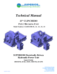
Technical Manual
15" CLINCHER®
TYPE 3 BUCKING UNIT
Model Numbers CLEBU1500-30 & -32
MODEL CLEBU1500-30
(with console)
MODEL CLEBU1500-32
CLINCHER Electrically Driven
Hydraulic Power Unit
Model PU7560
1800 RPM, 60 Hz, 75 HP, 3000 PSI, 60 GPM
Technical Manual
15" CLINCHER®
TYPE 3 BUCKING UNIT
Model Numbers CLEBU1500-30 & -32
CLINCHER Electrically Driven
Hydraulic Power Unit
Model PU7560
1800 RPM, 60 Hz, 75 HP, 3000 PSI, 60 GPM
TABLE OF CONTENTS
Hazard Warnings
Description, Illustrations, Specifications, &
Certificate of Origin/Conformance
Wrap Around Die Selection
Installation Instructions / Lubrication Specs
Operating Instructions, Controls & Instrumentation,
Hydraulic Schematic
Maintenance Instructions & Trouble Shooting
Options and Accessories
Bucking Unit Component Illustrations
Motor Service Manuals
Hydraulic Pressure Intensifier Systems
Operating Procedures
Pump Service Manual and Technical Data
Hydraulic Power Unit Parts List & Illustrations
Control Valve Technical Data
1
2
3
4
5
6
7
8
9
10
11
12
HAZARD WARNING
Nomenclature used in this manual:
WARNING Concerns an operating procedure or practice
that, if not strictly observed, can result in injury
to personnel or loss of life.
Caution
Concerns an operating procedure or practice
that, if not strictly observed, can result in
damage to or destruction of equipment.
Note
Concerns an operating procedure or practice that
needs highlighting.
CLINCHER® Bucking Units are manufactured to provide a
means of making up or breaking out high torque tubular
connections. They utilize high pressure hydraulic fluid power
which can cause the unit to move suddenly and with great
force if not properly anchored. The pipe can also move when
the unit is not anchored and if the pipe is bent or is not
adequately supported. CLINCHER® Bucking Units contain
rotating and reciprocating parts which can severely or fatally
injure personnel who are operating, repairing, or near this
equipment during its operation.
WARNING: Bucking Units and Power Units must be
maintained and operated by trained personnel. Personnel with
diminished physical or mental capacity must not operate this
equipment. No work of any type, including changing of dies,
is to be carried out while the Bucking Unit is connected to the
Hydraulic Power Unit.
CLINCHER® Bucking Units and Hydraulic Power Units
utilize high pressure hydraulic fluids. Portions of the unit,
control valves, hydraulic lines and cylinders may contain high
pressure fluid even when the Power Unit is de-energized and
the fluid supply hoses are disconnected. During normal
operation the temperature of the hydraulic fluids as well as
hoses, piping, valves, etc., can rise to a level which can cause
burns.
WARNING: Personal protective gear including safety
glasses, face shields, protective gloves and protective clothing
must be worn to guard against the hazards of high pressure
fluids.
Tight fitting clothing is required to prevent
entanglement in rotating components. These units should be
serviced by thoroughly trained and qualified hydraulic
technicians using procedures to safely insure hydraulic
pressure is bled from these circuits.
No attempt should be made to operate the CLINCHER®
Bucking Unit for any purpose other than which it is intended.
This system is capable of generating very large clamping
forces and torsional loads which, if improperly applied or
controlled, could result in damage to the tubular, to the
Bucking Unit, or could possibly result in injury or death of
personnel. Do not attempt to operate the unit without correct
dies and the proper size tubular being in the tong and backup
sections of the Bucking Unit. See Section 3 for more
information concerning the selection and use of dies.
CAUTION: Operating this equipment without the correct
size, type, and orientation of dies can result in damage to the
equipment or tubulars being handled.
WARNING
TWO TROLLY SHIPPING BRACKETS, TWO BACKUP SHIPPING HOLD DOWN BOLTS AND TWO
BACKUP SHIPPING SPACERS MUST BE REMOVED BEFORE ATTEMPTING TO OPERATE THIS
BUCKING UNIT. THESE COMPONENTS ARE PAINTED YELLOW AND PICTURED BELOW.
Failure to remove these components will result in severe equipment damage that will void all warranties.
SUPERIOR Manufacturing & Hydraulics, Inc.
15" CLINCHER® BUCKING UNIT
Revision: 01/06
Page 1 - 1
CROSS
GENERAL INFORMATION
HYDRAULIC PRODUCT
SAFETY
HYDRAULIC PRODUCT SAFETY
WARNING: Valve lever (spool) may "stick" (not center) under
certain conditions allowing the hydraulic equipment to continue to
operate and could cause serious injury, death or equipment failure.
VALVE SAFETY: Read and follow instructions carefully. Failure to observe instructions
and guidelines may cause serious injury, death or equipment failure. A sticking valve
(spool bind) may be caused by one or more of the following factors:
DIRTY OIL: Oil must be filtered to a minimum of 25 microns. Filters should be changed regularly spin-on types after 50 hours of initial use and then after every two hundred fifty hours of use. Use of
a condition indicator is recommended. Consult your tractor or implement owner=s manual for filtration and changing recommendations for internal systems.
OIL REQUIREMENTS: Premium quality anti-wear type oil with a viscosity between 100 and 200
SSU at operating temperatures. Certain synthetic oils may cause spool seals to swell and the valve
to stick. If in doubt, call CROSS Engineering.
IMPROPER HOOK UP OR MOUNTING: Always use the proper size fittings. Hook up "in" & "out"
as noted on the valve body. Do not overtorque pipe fittings. Mounting surfaces should be flat and
care should be used when tightening mounting bolts. Over-tightened bolts can cause spool bind
and casting breakage. When hooking a valve in series, always use a power beyond sleeve. Consult your tractor or implement manual to make sure you have the proper quick disconnect line
connected to the inlet of the remote valve.
MISAPPLICATION: Always use the proper valve for the job. CONVERTA, CD, CS or CA valves
should never be used for metered heavy load lifting - loaders or similar applications. Use an open
center valve for open center applications and a closed center valve for closed applications. If in
doubt, check with your tractor dealer. Contact CROSS if the valve allows the hydraulic equipment to
creep excessively.
MAINTENANCE: Make sure all bolts are tightened and torqued to the recommended specification.
Bent or broken parts should not be used. Replace immediately. Always use exact replacements.
Always protect valve spool from paint overspray.
Faulty quick disconnects can cause high back pressures and sticking spools. Check quick disconnects periodically to make sure they are functioning properly. If valve spool does not center or
appears to stick, do not use!
PUMPS & MOTORS SAFETY:
A relief or bypass in your hydraulic system is necessary to prevent pump from breakage due to
overpressurization. Use correct fittings and proper oil as noted in the technical service manual
packed with each unit. Change oil as recommended by your implement or tractor manufacturer.
CYLINDER SAFETY:
Check clevis clearances before, during and after extending the cylinder and before using the cylinder
under pressure to avoid possible injury, or bent or broken rods caused by binding. Never operatea
cylinder above recommended pressures. Never use a cylinder as a safety device when trans-porting
equipment.
PINHOLE LEAKS:
If you observe a pinhole leak, discontinue use of the component. If oil has penetrated your skin or
contacted your eye, seek medical attention immediately!
Page 1 - 2
DESCRIPTION
SUPERIOR Manufacturing & Hydraulics’ CLINCHER®
BUCKING UNITS are used to make up or break out tubular
connections in a horizontal position. They are most frequently
used in steel mills, pipe yards, or workshop environments.
While they are readily transportable and can be trailer
mounted, Bucking Units are not usually used at a drill site.
For drill site applications, refer to our CLINCHER®
MAKE/BREAK Tool Operating Manual for information
regarding a compact high torque unit.
SUPERIOR Manufacturing & Hydraulics produces three
different types of Bucking Units. Type One is primarily
intended for use in pipe mills or pipe yards for the installation
(make up) or removal (break out) of couplings. This unit will
readily accommodate different sizes of tubulars while allowing
the spacing between the tong and backup to be adjusted
approximately two feet. When using this type of unit the
couplings and tubulars must be fed through either the backup
or tong into the other component.
CLINCHER® BUCKING UNITS utilize the patented
CLINCHER® Die System which features a self aligning
spline system that wraps around the pipe providing coverage
up to 330 degrees. The dies distribute the radial load over the
largest possible area to minimize pipe stress and deformation.
Three different types of dies are available. Our fine tooth steel
dies provide the highest possible torque transmission with
minimal pipe marking. Non-marking aluminum dies are
available for use with fiberglass or corrosion resistant alloy
(CRA) tubulars. CLINCHER® GRIT FACE™ dies are
available for chrome and stainless steel tubing applications
where steel dies are not acceptable and which require greater
torque capacity than non-marking aluminum dies can provide.
Adapters which utilize Dovetail strip dies may be available on
special order. See Section 3 for more information concerning
Die selection and usage.
The Type Two and Type Three (see Figure 1) Bucking Unit is
used for the make up or break out of tool assemblies which
have varying diameters and lengths. The Type Two and Type
Three unit will readily accommodate different sizes of
components. The tong and backup spacing can be adjusted
from a few inches to many feet.
CLINCHER® BUCKING UNITS have three main
components (see Figure 1):
(1) A powered, rotating tong assembly with hydraulically
operated jaws which grip the tubular’s coupling.
The Type Two unit features a chain driven tong with a top
loading, open style LOCKJAW™ Backup to allow easy
installation or removal of tubulars or tools using an overhead
crane.
The Type Three unit features a gear driven tong with either a
Closed Head Backup (Type 1) or a top loading, open style
LOCKJAW™ Backup (Type 2).
BACKUP
ASSEMBLY
TONG
ASSEMBLY
FRAME
SYSTEM
(2) A non-rotating backup assembly with hydraulically
operated jaws which grip the body of the tubular.
(3) A frame system which supports the first two items and
contains the drive mechanisms and Bucking Unit Control
Panel.
A separate hydraulic power unit is required to supply the
required hydraulic power to drive the tong and operate jaws.
FIGURE 1
CLINCHER® TYPE 3
BUCKING UNIT
SUPERIOR Manufacturing & Hydraulics, Inc.
15" CLINCHER® BUCKING UNIT
Revision: 01/06
Page 2 - 1
28"
20 3/8"
65"
120" FRAME OVERALL LENGTH
73"
126 1/2" OVERALL LENGTH
FIGURE 2
APPROX. WEIGHT (LBS.) = 13618
15" BUCKING UNIT
DIMENSIONS
CLEBU1500-30
4225 HWY. 90 EAST
BROUSSARD, LA 70518
(318) 837-8847
THIS DOCUMENT IS THE PROPERTY OF SUPERIOR MANUFACTURING &
HYDRAULICS AND IS CONSIDERED CONFIDENTIAL. THIS INFORMATION
MAY NOT BE USED, DISCLOSED, COPIED, OR REPRODUCED IN ANY
FORM, WITHOUT THE EXPRESS WRITTEN CONSENT OF SUPERIOR
MANUFACTURING & HYDRAULICS.
REV. #
LOG #
01/05/06
DATE
REF: P:\Manuals\Equip Manuals\Dwgs\
CLEBU1500-30\Dimensions.wpg
73"
46 3/4"
Page 2 - 2.1
15" BUCKING UNIT
DIMENSIONS
CLEBU1500-32
70 3/4"
130 1/2"
APPROX.WEIGHT (lbs.) = 13319
4225 HWY. 90 EAST
BROUSSARD, LA 70518
(318) 837-8847
THIS DOCUMENT IS THE PROPERTY OF SUPERIOR MANUFACTURING &
HYDRAULICS AND IS CONSIDERED CONFIDENTIAL. THIS INFORMATION
MAY NOT BE USED, DISCLOSED, COPIED, OR REPRODUCED IN ANY
FORM, WITHOUT THE EXPRESS WRITTEN CONSENT OF SUPERIOR
MANUFACTURING & HYDRAULICS.
REV. #
LOG #
DATE
SPECIFICATIONS for
CLINCHER® BUCKING UNITS
TOOL SIZE
Unit Style (CLEBU1500-30)
15
Type III Unit
w/ LOCKJAW™
Backup
Backup Torque Gauge Handle
35" (1)
Min Tubular OD (in) (5)
2.062"
Max Tubular OD (2) (in)
15.000
(3)
Standard Torque Rating (ft lbs)
CLEBU1500-30
Dies per Tong or Backup
(4)
Drive Type
50,000
4
Hydraulic
Number of Drive Speeds
2
Max. Hydraulic Power Unit
Operating Pressure (psi)
3,000
Max. Clamping Pressure (psi)
Intensified using air operated pump
4,500
SPECIFICATIONS for
CLINCHER® BUCKING UNITS
TOOL SIZE
15
Unit Style (CLEBU1500-32)
Type III Unit
w/ LOCKJAW™
Backup
Backup Torque Gauge Handle
35 " (1)
(5)
Min Tubular OD (in)
2.062"
Max Tubular OD (2) (in)
15.000 "
Standard Torque Rating (3) (ft lbs)
100,000
Series Mode: (6) (8)
High Speed / Low Torque
12 rpm max. / 25000 ft/lbs max.
Low Speed / High Torque
6 rpm max. / 50000 ft/lbs max.
Parallel Mode: (8)
High Speed / Low Torque
6 rpm max. / 50000 ft/lbs max.
Low Speed / High Torque
3 rpm max. / 100000 ft/lbs max.
Dies per Tong or Backup (4)
3/each, 6/total
Drive Type
Hydraulic
Number of Drive Speeds
2
Max. Hydraulic Power Unit Operating
Pressure (psi)
3,000
Max. Clamping Pressure (psi)
Intensified using air operated pump (7)
4,500
Important Notes:
1
2
3
4
5
6
7
8
Handle length is based on use of 8.75" OD (see illustration of Tandem Load
Cell Retainer). Reduction from Pinion Shaft (where encoder is attached) to
Ring Gear is 8.308:1. Small diameter electronic loadcells may require a
bushing or mounting plates to maintain 35" handle length. If diameter of
loadcell changes, handle length will change.
The maximum tubular OD is the limit of the diameter which can be handled in
this unit. The end user should carefully review the maximum diameter of the
coupling for the tubular being handled to insure it can be accommodated in the
CLINCHER® BUCKING UNIT. Contact the manufacturer if other diameters
are required.
Note: After installing electronic load cell in retainer bracket, the load cell must
be rotated to close the gap until the button just contacts the load cell brace
(Ref. pg. 8-17, Item 4, PN BUCS23204).
Higher torque ratings available upon request.
Dies and die adapters must be ordered separately.
This unit will accommodate large and small diameter tubular goods. Users
should exercise caution when making up small diameter low torque
connections. Testing should be performed to confirm torque turn system will
dump pressure quickly enough to prevent over torquing connections. Reduced
rotational speed when approaching make up torque may be required.
Requires optional series/parallel valve.
Requires 125 PSIA 10 SCFM air supply.
Speeds when driven by 40 HP electric hydraulic power unit with 60 GPM
variable displacement hydraulic pump.
SUPERIOR Manufacturing & Hydraulics, Inc.
15" CLINCHER® BUCKING UNIT
Revision: 07/07
Page 2 - 3
Tandem
Load Cell Retainer
Page 2 - 4
CLINCHER® DIES
Many CLINCHER® Tongs and Backups utilize jaws and/or
adapters which accept Dovetail Inserts (AKA Pencil Dies or
Strip Dies) to effectively grip tubulars. Jaw systems and jaw
adapters are also available which accommodate Wrap-Around
Fine Tooth Steel Dies, GRIT FACE™ Dies and Aluminum
Dies.
15
TYP
.
15
TYP
.
OA
L
L
OA
W
W
Thickness Width
5/16
5/16
5/16
3/8
3/8
3/8
5/8
5/8
5/8
5/8
5/8
5/8
OAL
P/N
Straight
Tooth
P/N
Diamond
Tooth
3 1/2
3 7/8
4 1/2
3 1/2
3 7/8
4 1/2
¹
DTI4052
DTI4002
DTI4030
DTI4051
DTI4001
¹
¹
¹
¹
¹
¹
STRAIGHT TOOTH
Note:
DIAMOND TOOTH
Diamond Tooth Dies are used when a more
aggressive bite is required.
SUPERIOR Manufacturing & Hydraulics, Inc.
15" CLINCHER® BUCKING UNIT
Revision: 01/06
The appropriate jaws, die adapters and dies required for a
specific tubular OD are also described in this section of the
manual.
Thickness Width
T
T
The drawings in this section describe the jaw and adapter
systems.
Page 3 - 1
OAL
17/32
5/8
3 1/2
17/32
5/8
3 7/8
17/32
5/8
4 1/2
5/8
5/8
3 1/2
5/8
5/8
3 7/8
5/8
5/8
4 1/2
11/16
5/8
3 7/8
11/16
5/8
4 1/2
3/8
1
3 7/8
3/8
1 1/4 3 7/8
3/8
1 1/4
5
7/16
1 1/4 3 7/8
7/16
1 1/4
5
1/2
1 1/4 3 7/8
1/2
1 1/4
5
9/16
1 1/4 3 7/8
9/16
1 1/4
5
5/8
1 1/4 3 7/8
5/8
1 1/4
5
11/16
1 1/4 3 7/8
11/16
1 1/4
5
3/4
1 1/4 3 7/8
3/4
1 1/4
5
3/4
1 1/4 5 7/8
13/16
1 1/4 3 7/8
13/16
1 1/4
5
7/8
1 1/4 3 7/8
7/8
1 1/4
5
1
1 1/4 3 7/8
1
1 1/4
5
¹ Available upon request.
P/N
Straight
Tooth
P/N
Diamond
Tooth
DTI4031
DTI4053
DTI4003
DTI4032
DTI4054
DTI4004
DTI4055
DTI4005
DTI1505
DTI1614
DTI1610
DTI1612
DTI1617
DTI1601
DTI1602
DTI1622
DTI1623
DTI1632
DTI1633
DTI1642
DTI1646
DTI1651
DTI1693
DTI1662
DTI1661
DTI1664
DTI1671
DTI1673
DTI1691
DTI1697
¹
¹
¹
¹
¹
¹
¹
¹
¹
¹
¹
DTI1612D
DTI1617D
DTI1601D
DTI1602D
DTI1622D
DTI1623D
DTI1632D
¹
¹
¹
¹
¹
DTI1662D
¹
¹
¹
¹
¹
¹
CLINCHER® WRAP-AROUND DIES
CLINCHER® wrap around dies are available in three types:
Fine Toothed Steel Dies: for low to ultra high torque applications on carbon steel tubulars including tubing,
casing and drill pipe
Smooth Faced Aluminum Dies: for low to moderate torque
applications on fiberglass and corrosion resistant
alloy (stainless steel) tubulars
GRIT FACE™ Dies: for low to high torque applications on
fiber-glass and corrosion resistant alloy (stainless
steel) tubulars where the use of steel dies is
prohibited as well as on carbon steel tubulars where
reduced marking is desired
CLINCHER® Bucking Units utilize wrap around dies to
maximize pipe coverage allowing maximum torque
transmission while minimizing marking and virtually
eliminating the possibility of deforming the pipe. These tools
have 3 or 4 jaws which accept our dies. CLINCHER® Dies
are designed to match the OD of the tubing, casing, coupling
or accessory being made up or broken out. Each die is
stamped on the top or side to identify its size.
Using fine toothed steel dies which are slightly larger than the
tubular is acceptable provided the difference in diameters is
less than 3/32" (0.093"). The fine toothed steel dies we are
providing for pipe and couplings are manufactured with an ID
which is approximately 0.050" larger than the nominal die
size. This provides a die which will readily grip pipe and
couplings which are manufactured to API external diameter
tolerances. In the case of pipe and couplings whose nominal
OD is greater than 5 1/2", the API maximum diameter
tolerance range can theoretically exceed the die diameter.
Should this situation arise, the die will still grip the pipe but
will have reduced contact area as the pipe may not contact the
die along its midline. It is important to note we have not had
any reports of die problems with extremely oversized tubulars.
This is probably due to the fact that modern mills are able to
control the OD of their products to much tighter tolerances
than permitted by the API standards.
Aluminum and GRIT FACE™ dies should be matched with
the specific tubular diameters required. Our non-marking
aluminum die system is manufactured with an ID which is
0.035" larger than the nominal die diameter. We have to use a
closer fit between the nominal tubular and the die since this
system relies on radial loads and the coefficient of friction
instead of teeth. This clearance also allows the installation of
our silicon carbide screen cloth which is required when using
the non-marking system at high torques.
Note: The use of improperly sized dies can result in reduced
torque capacity, increased pipe marking and reduced die life.
SUPERIOR Manufacturing & Hydraulics, Inc.
15" CLINCHER® BUCKING UNIT
Revision: 01/06
Page 3 - 2
The bucking unit cylinders (which hold our dies) have
considerable stroke which could cause some people to believe
they can use a die on a tube which is significantly smaller than
the nominal size. For example, someone could use a 7" die to
grip on a non-standard tubular with an OD of 6.75". While
one could successfully grip tubulars with such an arrangement,
the pipe would not be exactly centered within the rotating and
fixed portions of the bucking unit. The resulting eccentric
pipe movement seen when rotating the collar could cause
some variation in apparent torque readings. Therefore, we
recommend nominal die sizes be matched to specific pipe or
coupling diameters and using specially manufactured dies for
non-standard premium couplings.
CAUTION: Do not attempt to grip tubular diameters which
are larger than the dies being used. Failure to observe this
precaution can result in damage to the tubular or the bucking
unit.
CAUTION: Do not attempt to use combinations of different
die sizes to accommodate a nonstandard tool joint or coupling
OD when the correct size dies are not available. Using
mismatched die sizes or different die types can cause the
tubulars to run eccentrically resulting in erratic torque
measurements. This can also initiate thread galling.
CLINCHER® Wrap-Around Dies are manufactured in
specific diameters to match standard tubing and casing
diameters, API coupling diameters, selected work string
connection diameters and certain commonly used premium
connection coupling diameters. CLINCHER® Wrap-Around
Dies should not be used on tubulars which are larger than the
nominal die size. Steel toothed dies can be used on tubulars
which are no smaller than 3/32" (0.093") less than the nominal
die size. Aluminum and GRIT FACE™ dies should be
matched with the specific tubular diameters required.
Note: Fine toothed steel dies in sizes 7 5/8" and smaller are
normally stocked in our Broussard, Louisiana facility.
Aluminum and GRIT FACE™ Dies are normally made to
order although a limited range of sizes and small quantities
may be available from stock.
Contact SUPERIOR
Manufacturing & Hydraulics, Inc. for information concerning
availability of stock, large diameter and special die sizes.
CLINCHER® WRAP-AROUND DIES
DIE Nomenclature for CLINCHER® Bucking Unit
BUC1500-xxxx
fine toothed steel dies available in sizes
from 15" to 11 3/4"
BUCA1500-xxxx
aluminum dies available in sizes from
15" to 11 3/4"
BB1500-xxxx
GRIT FACE™ dies (contact Superior
f/ size availability)
Note when using dies on tubulars with OD of 11 3/4" or less it
is necessary to install reducing adapters in the bucking unit
cylinder. (Die Adapter 15"-11 3/4" P/N BUA15-11750A,
15"-10 3/4" P/N BUA15-1075A and Die Adapter 15"-8 5/8"
P/N BUA15-8625A..) The adapters will accommodate smaller
sizes listed below.
CLEBU1175-xxxx
CLEA1175-xxxx
BB1175-xxxx
fine toothed steel dies available in sizes
from 11 3/4" to 7 5/8"
aluminum dies available in sizes from
11 3/4" to 7 5/8"
GRIT FACE™ dies available in sizes
from 11 3/4" to 7 5/8"
SUPERIOR Manufacturing & Hydraulics, Inc.
15" CLINCHER® BUCKING UNIT
Revision: 07/07
Page 3 - 3
BUC7625-xxxx
BUCA7625-xxxx
BB7625-xxxx
fine toothed steel dies available in sizes
from 7 5/8" to 2 1/16"
aluminum dies available in sizes from
7 5/8" to 2 1/16"
GRIT FACE™ dies available in
sizes from 7 5/8" to 2 1/16"
ORDERING EXAMPLE: Fine toothed steel dies are needed
to makeup 8 5/8" OD casing with 9 5/8" OD couplings
Qty. Req’d: Six pieces BUA1500-11750
(for tong and backup assembly)
and
Qty. Req’d: Three pieces BUC1175-9625
(for tong assembly)
and
Qty. Req’d: Three pieces BUC1175-8625
(for backup assembly)
(Replace xxxx with size req’d in inches)
Contact SUPERIOR Manufacturing & Hydraulics, Inc.
for information concerning availability of stock and special
die sizes.
Page 3 - 4
CLEBU1500-32
Tools & Equipment Required
for Setup and Commissioning
Laser transit and qualified operator to align bucking unit
with pipe racks
Welding machine and qualified welder to fix foot positioner washers to bucking unit mounting feet
Wire brush to clean up weld zone and touch up paint
(2) sets of 1/2” to 1 1/8” open/box end wrenches
(1) 1/2” Drive set of 1/2” to 1 1/8” sockets
(1) 1/2” Drive set of 5/16” to 5/8” allen sockets
(1) 1 1/2” Socket
(1) 1 7/16” Socket
(1) 3/32” Allen wrench
(2) 5/16” Allen wrenches
(1) 15/64” Allen wrench
(1) 1/2” Drive ratchet
(1) 1/2” Drive impact wrench
(2) 18” Crescent wrenches
(2) 18” Pipe wrenches
Set of screwdrivers (phillips and flathead)
Loctite 7649 activator
Loctite 542 thread sealant
Never Seez
150 gallons of premium hydraulic oil (Texaco Rando HD
68 or equivalent) as well as means to transfer and prefilter the oil from barrels to hydraulic power unit reservoir
Grease gun and grease specified in bucking unit technical manual
» If anchor bolts are not pre-installed in concrete slab:
Hammer drill and drill bits
3/4” diameter x 6” long or equivalent anchor bolts,
nuts, and locknuts
Adjustment Bolts
P/N HHCS 3/4”-10 x 5” GR8
Foot Positioner Washer
P/N CB11030-S16
Electrical Checklist
Anchor Down Feet
Washers are welded in place
and fastened to anchor down
floor lugs once bucking unit is
perfectly aligned
Vertical Adjustment Feet
Use to align center of bucking
unit tong vertically with pipe
rack system
Pusher Foot Weldment
P/N CB2335
Horizontal Adjustment Feet
Use to align center of bucking unit tong horizontally with
pipe rack system
Electrical cable *
Electrical conduit *
Misc. electrical parts to supply point to bucking unit *
At minimum, install at least one (1) 6’ long (2 meter)
ground rod to earth the hydraulic power unit and #2AWG
ground wires for use between the hydraulic power unit,
control console, and bucking unit (NOTE: These items
are not supplied as local electrical codes may dictate
other means) *
Wire cutters
Wire strippers
Volt / OHM meter
110/240 VAC 50/60Hz Uninterruptable Power Supply
(UPS) with electrical filter and surge suppressor for
WinCATT system and printer
» NOTE: Power to PLC, solenoids, and proportional
controller should be provided from a clean source
(not direct from a generator or mains where voltage
variation, surges, or outages are frequent)
Air Hookup Checklist
(1) CB11041 Regulator / filter
(1) 1480 Ball Valve
Fittings depending on proximity of unit from main line /
current setup
Minimum 50’of air hose (length may vary depending on
existing installation and proximity)
Contingency Materials
Safety Solvent for cleaning pneumatic & hydraulic quick
disconnects
Electrical contact cleaner solution
Soldering iron (for WinCATT cable connector repair)
Teflon tape or Loctite sealing compound
WORLDWIDE •YEARS AHEAD
PUBLISHED BY SUPERIOR MANUFACTURING & HYDRAULICS, INC.
4225 HWY 90 E • Broussard, LA 70518 USA
TEL: 337.837.8847 • FAX: 337.837.8839 • [email protected]
* Electrical material as required to suit installation and local electrical code
Page 4 - 1
Manual/PLC Controlled Bucking Unit
INSTALLATION & SETUP INSTRUCTIONS
IMPORTANT NOTICE: Insure steps 1 through 7
have been completed before notifying Superior
Manufacturing & Hydraulics that a factory technician
is needed to perform installation inspection and final
startup services. If these steps have not been
completed, additional charges will be applied while
our technician stands-by for the installation to be
completed by the buyer.
1.
UNPACK – Inspect for shipping damage and/or missing
items. Immediately document and report any suspected
shipping damage. Remove all banding straps and
protective coverings. Do not remove shipping bolts and
brackets before the Bucking Unit has been moved to its
final location and no further handling is required. Refer
to illustration on page 1-1 to identify location of shipping
brackets and bolts.
a.
2.
3.
Page 4 - 2
CAUTION: Failure to align rack centerline with
bucking unit may cause tubulars to hang on dies
when passing through the bucking unit.
Misalignment can result in unacceptable torque-turn
results.
d.
Remove shipping bolts/brackets/etc., as shown in
illustration on page 1-1.
5.
FILL POWER UNIT RESERVIOR WITH
HYDRAULIC FLUID - Unless specifically noted, all
hydraulic power units are shipped without hydraulic oil.
Refer to order documents to determine the volume of
hydraulic oil required to fill the hydraulic reservoir. The
SUPERIOR Hydraulic Power Units and the CLINCHER®
BUCKING UNIT are designed to work with conventional
industrial hydraulic oils. Superior Manufacturing &
Hydraulics utilizes TEXACO Rando HD 68 hydraulic oil.
Substitution of brands with comparable properties is
acceptable. Use of low viscosity fluids or high viscosity
fluids, synthetic, fire resistant or water-based fluids
should not be considered without consulting with
SUPERIOR Manufacturing and Hydraulics.
A JSA should be undertaken before commencing
installation work or using installed equipment.
Untrained personnel must not handle, install or
operate this equipment.
SUPERIOR Manufacturing & Hydraulics, Inc.
15" CLINCHER® BUCKING UNIT
Revision: 04/07
c.
INSTALL Control Console and Hydraulic Power Units at
locations as required. Refer to order documents for
lengths of hoses supplied with equipment.
WARNING - CLINCHER® 15” Bucking Units
weight more than 13,500 lbs. and must be handled
with appropriate equipment and procedure to
avoid exposing personnel to hazards or potentially
damaging the equipment.
INSTALL - CLINCHER® BUCKING UNITS must be
installed on a foundation suitable for the weight of the
unit, its accessories, pipe handling equipment plus the
weight of the heaviest tubulars being processed. Leveling
jacks are not provided (but are available as options) and
may be required to insure the unit is supported on each of
the four corners. When possible, we recommend the unit
be anchored to the foundation using 3/4" anchor bolts.
Install the bucking unit, hydraulic power unit and torque
turn control system as required on location. NOTE: If
pipe roller rack systems are being installed they must be
accurately leveled and aligned with the bucking unit to
deliver pipe into the bucking unit on the centerline of the
rotating tong.
SUPERIOR strongly recommends the use of our
LASER ALIGNMENT TOOLS to verify proper
alignment before permanently fixing anchor bolts.
4.
READ HAZARD WARNINGS and TECHNICAL
MANUAL – The first section of the technical manual
contains specific information about Operating Procedures
which if not strictly followed could result in serious
injury, loss of life, damage to equipment or damage to
tubulars. Other important information is contained
throughout the technical manual. Thoroughly familiarize
yourself and others working with you with this
information before commencing installation or operation.
a.
b.
6.
a.
CAUTION: Insure hydraulic fluid reservoir is
totally clean and dry before filling with oil. All
hydraulic fluids, including new hydraulic oil, must be
filtered to 5 microns before adding to the reservoir.
Fill the hydraulic reservoir with the appropriate
filtered hydraulic fluid to within 4 inches from top of
reservoir.
b.
CAUTION: Insure the suction isolation valve is
open before starting power unit. Failure to open
this valve will cause catastrophic pump failure.
c.
Note: The electrically driven hydraulic power unit is
equipped with a low fluid level switch which will
automatically shut down HPU electrical motor if
fluid level drops below safe operating level. Refill
unit before attempting to restart HPU. Some units
may be equipped with optional second fluid level
warning lamp which will flash when fluid level is
low but not low enough to cause HPU shutdown.
CONNECT HOSES - Remove all hose dust caps as
required and clean all hydraulic quick disconnect
couplings with safety solvent and blow dry using lowpressure compressed air.
Manual/PLC Controlled Bucking Unit
INSTALLATION & SETUP INSTRUCTIONS
7.
a.
Connect airlines to DE-ENERGIZED source of clean
and dry air with maximum supply pressure of 120
psi.
b.
Connect hydraulic hoses and insure all quick
disconnects are fully seated. Connect case drain line
directly to reservoir, do not attach to a return circuit.
c.
CAUTION: Failure to connect case drain circuit
directly to hydraulic reservoir will result in motor
shaft seal failure and cause hydraulic leakage that
will not be covered by your warranty.
d.
Failure to connect load sense line will inhibit the
hydraulic power unit’s ability to automatically shift
into a standby mode when work is not being
performed. This may cause undesirable heat build
up, higher energy costs, and could result in shortened
life of hydraulic fluid and/or components.
ELECTRICAL POWER FOR HYDRAULIC POWER
UNIT – LOCKOUT ELECTRICAL POWER AT
DISTRIBUTION POINT. Refer to order documents to
determine the electrical voltage and power requirements.
DO NOT ENERGIZE CIRCUITS AT THIS TIME.
a.
Connect appropriate electrical power to motor starter.
Connect remote control cord from control console to
hydraulic power unit’s motor starter enclosure.
b.
Insure all components are electrically interconnected
with heavy gauge ground wires and to a suitable
ground rod.
c.
CAUTION:
Use locally licensed electrical
contractors to insure proper hookup complying
with local electrical codes.
8.
If unit is to be started up by Superior’s factory
technicians, STOP installation procedures now and
notify Superior Manufacturing & Hydraulics that the
unit is now ready for Superior’s technicians to
perform startup services. If owner is performing
installation and startup, follow procedures in step 9.
9.
INITIAL START UP –
a.
CAUTION: Insure all control valve levers are in
neutral position.
1) Remove cover from HPU pump motor adapter
housing.
2) Energize electrical power to HPU starter. Do not
energize air supply at this time.
3) Set control console selector switch to manual control
(for PLC controlled units only).
SUPERIOR Manufacturing & Hydraulics, Inc.
15" CLINCHER® BUCKING UNIT
Revision: 04/07
Page 4 - 3
4) Bump Start and Stop motor controls to verify motor
direction of rotation is correct as indicated by
directional arrow on HPU coupling housing.
CAUTION:
Running pump in the wrong
direction will cause catastrophic pump failure
which will not be covered by manufacturer’s
warranty. Change direction of motor rotation if
required by swapping electrical phases in motor
starter enclosure.
5) De-Energize electrical power to HPU starter.
Reinstall cover on HPU coupling housing.
6) Energize electrical power to HPU starter. Start HPU
using switch on console and allow HPU to run for 10
minutes to purge air from primary circuits while
monitoring for leakage.
7) Shift mode shift valve lever to “LOW” position.
8) Slowly shift motor valve lever from neutral to
“MAKEUP” position and allow the unit to rotate for
1 minute.
9) Shift motor valve lever to “BREAKOUT” position
and allow the unit to rotate for 1 minute.
10) Shift mode shift valve lever to “HIGH” position
while rotating in “BREAKOUT” for one minute.
11) Reverse motor valve lever to “MAKEUP” and allow
unit to rotate for 1 minute.
12) Release motor valve lever.
13) Return mode shift valve lever to mid or neutral
position.
14) Verify hydraulic power unit automatically shifts from
operating mode to standby mode by observing
system pressure gage dropping to approximately 500
psi a few seconds after the demand for power has
been removed.
15) Actuate tong clamp valve lever to extend clamping
cylinders. Release lever and allow it to return to the
neutral position. CAUTION: Do not allow
pressure to build beyond 1,000 psi unless the dies
and pipe are installed. Pressurizing the tong
clamping cylinders without dies and pipe in
position can cause failure of the cylinder gland
bolts.
16) Actuate tong clamp valve lever to retract clamping
cylinders. Release lever and allow it to return to the
neutral position.
17) Repeat steps 15) and 16) six (6) times.
18) Actuate backup clamp valve lever to extend
clamping cylinder. Release lever and allow it to
return to the neutral position. CAUTION: Do not
allow pressure to build beyond 1,000 psi unless
the dies and pipe are installed. Pressurizing the
backup clamping cylinder without dies and pipe
in position can cause failure of the cylinder gland
bolts.
Manual/PLC Controlled Bucking Unit
INSTALLATION & SETUP INSTRUCTIONS
19) Actuate backup clamp valve lever to retract clamping
cylinder. Release lever and allow it to return to the
neutral position.
20) Repeat steps 18) six (6) times and 19) five (5) times
leaving backup in closed position.
21) For bucking units equipped with optional hydraulic
jacks, pipe rollers, backup carriage positioners, etc.,
duplicate steps 18), 19) and 20) for each control
valve and circuit to purge air and confirm proper
operation.
22) STOP HPU using switch on console.
23) Release any trapped hydraulic pressure by fully
actuating all control valve levers in both directions
several times.
24) Top off hydraulic fluid level in reservoir to makeup
for volume of fluid used to fill lines and cylinders.
NOTE: Some HPU’s may be equipped with optional
fluid level sensors which will shut down the HPU if a
low fluid level condition develops.
25) INSTALL LOCKOUT on electrical disconnect.
26) Install compression load cell (hydraulic or electronic
as applicable) through “MAKEUP” window into
position within the backup. CAUTION: Load cells
with diameters other than 8.750 inches will alter
torque handle length and will require compensation to indicate correct torque.
27) Attach hydraulic torque gage to control console or rig
up electronic torque turn system’s turns encoder,
electronic load cell and hydraulic dump valve
solenoid cables (supplied by others) using third party
instructions as applicable. Set torque turn system for
test sub connection’s makeup torque.
28) Install dummy load cell (aluminum or steel blank)
through “BREAKOUT” window into position within
the backup.
29) Obtain test sub with threaded connection and start
coupling by hand.
30) Install correctly sized dies in tong and backup.
REFER TO OPERATING INSTRUCTIONS, DIE
INSTALLATION page 5-2 for details regarding die
installation and operation.
31) REMOVE LOCKOUT from electrical disconnect.
32) Restart HPU.
33) Actuate backup clamp valve lever to retract clamping
cylinder and open the backup. Release lever and
allow it to return to the neutral position.
34) STOP HPU using switch on console.
SUPERIOR Manufacturing & Hydraulics, Inc.
15" CLINCHER® BUCKING UNIT
Revision: 04/07
Page 4 - 4
35) Install test sub in bucking unit with midline of
coupling approximately adjacent to end of dies in tong
to avoid clamping on female thread to be made up.
36) Insure test sub is level, positioned vertically on
center in tong and aligned with centerline of the
bucking unit.
37) RESTART HPU.
38) Actuate tong clamp valve lever to extend clamping
cylinders and clamp on the test sub’s coupling.
System pressure should rise to approximately 2500
psi or pressure established by operator for specific
tubular application. CAUTION: Use minimum
clamping pressure possible to avoid possible
crushing damage to tubular goods. Release the
lever and allow it to return to the neutral position.
39) Actuate backup clamp valve lever to extend
clamping cylinder. System pressure should rise to
approximately 2500 psi or pressure established by
operator for specific tubular application. CAUTION:
Use minimum clamping pressure possible to avoid
possible crushing damage to tubular goods.
Release lever and allow it to return to the neutral
position.
40) NOTE: If using smooth aluminum dies or if slippage
is experienced, torque capability may be increased
by using GRIT FACE™ or steel dies. Alternately
increasing clamping pressure using intensifiers may
provide higher torque capability. Refer to Air Driven
Hydraulic Intensifier information on pages 10-1 and
10-2.
a)
Energize air circuit. CAUTION: Use minimum
clamping pressure possible to avoid possible
crushing damage to tubular goods.
CAUTION: Do not actuate intensifiers unless
the pipe and the correct sizes of dies are
installed in the tong and backup. Failure to
comply with this requirement will cause
extensive equipment damage and expose
personnel to dangerous high pressure
hydraulic leaks.
b) Actuate tong clamp valve lever to extend
clamping cylinders and clamp on the test sub’s
coupling. System pressure should rise to
approximately 2500 psi or pressure established
by operator for specific tubular application.
CAUTION: Use minimum clamping pressure
possible to avoid possible crushing damage to
tubular goods. While holding the control valve
lever in the clamp position, rotate the tong clamp
intensify valve allowing air pressure to drive
Manual/PLC Controlled Bucking Unit
INSTALLATION & SETUP INSTRUCTIONS
tong’s booster pump. Pressure will rise in the
tong to approximately 3500 psi and can be
observed on the pressure gage in the tong head.
Release the lever and allow it to return to the
neutral position.
c)
Actuate backup clamp valve lever to extend
backup clamping cylinder and clamp on the test
sub. System pressure should rise to approximately 2500 psi or pressure established by
operator for specific tubular application.
CAUTION: Use minimum clamping pressure
possible to avoid possible crushing damage to
tubular goods. While holding the control valve
lever in the clamp position, rotate the backup
clamp intensify valve allowing air pressure to
drive backup booster pump. Pressure will rise in
the backup to approximately 3500 psi and can be
observed on the pressure gage in the backup.
Release the lever and allow it to return to the
neutral position.
d) Return tong and backup intensify valves to the
off position.
41) Shift mode valve lever to “LOW” position. Note:
Connections requiring a large number of turns can be
rotated in “HIGH” mode to reduce makeup time.
Connections requiring makeup torques greater than
50% of the Bucking Units maximum torque rating
will require shifting to “LOW” mode to complete
makeup to final torque.
42) Slowly shift motor valve lever from neutral to
“MAKEUP” position and allow the unit to rotate
until desired makeup torque is observed on the torque
gage. Immediately release the motor valve lever and
allow it to return to the neutral position to avoid
over-torquing the connection. Alternately hold the
motor valve lever in the “MAKEUP” position until
the torque turn computer system reads the required
makeup torque and opens the dump valve to stop
rotation. Immediately release the motor valve
control and allow it to return to the neutral position.
a)
To break out connection, slowly shift motor
valve lever from neutral to “BREAKOUT”
position and allow the unit to rotate until the
connection has backed off at least two turns.
43) Actuate tong clamp valve lever to retract clamping
cylinders. Release lever and allow it to return to the
neutral position.
44) Actuate backup clamp valve lever to retract clamping
cylinder.
45) STOP HPU using switch on console.
SUPERIOR Manufacturing & Hydraulics, Inc.
15" CLINCHER® BUCKING UNIT
Revision: 04/07
Page 4 - 5
46) Release any trapped hydraulic pressure by fully
actuating all control valve levers in both directions
several times.
47) Bucking unit should now be ready for operation.
Refer to technical manual to review maintenance
procedures and for selecting, changing, and using
dies.
FOR USERS OF REMOTELY OR AUTOMATICALLY OPERATED EQUIPMENT USING PLC
CONTROLLERS PLEASE MAKE NOTE OF
RECOMMENDED OPERATING PROCEDURES
AND SETUP LISTED IN STEP 10.
10. Refer to electrical schematic for connecting PLC to
electrical terminal strip located in control console
enclosure. Note: Electrical cables between valves and
enclosure are long enough to allow the enclosure to be
removed from the interior of the console for easy
servicing. Refer to Solenoid Power Requirements and
table on page 5.
a.
Manually setup bucking unit for pipe to be made-up
including selecting and installing dies in tong and
backup, adjusting system hydraulic pressure,
determining if pressure intensification is required, if
pipe will be made up using “high” mode, “low”
mode or combination of high and low modes. Note
some units may also have “series high” and “parallel
low” controls to increase rotational speed.
b.
Insure PLC is programmed for the following typical
sequence of makeup operations.
1) Energize hydraulic power unit.
2) Optional - Verify hydraulic system pressure is
available.
3) Optional – Verify air pressure is available.
4) Optional – Verify absence of coupling in tong.
5) Energize tong release circuit to insure cylinders
are retracted.
6) Energize backup release circuit to insure
cylinder(s) is (are) retracted.
7) Verify tong centering cylinder is in bottom dead
center (BDC) position (sense using customer
supplied proximity sensor or absolute encoder).
a)
If centering cylinder is not in BDC position,
energize the gear shift valve solenoid to
shift to “low gear” position.
Manual/PLC Controlled Bucking Unit
INSTALLATION & SETUP INSTRUCTIONS
REMOTELY OPERATED BUCKING UNITS REQUIRE OPTIONAL ELECTRICALLY CONTROLLED
SOLENOID OPERATED HYDRAULIC CONTROL VALVES. ELECTRICAL CONTROL PANELS,
PROGRAMMABLE CONTROLLERS, POWER SUPPLIES AND SENSORS ARE OPTIONAL AND
NOT INCLUDED. END USERS WHO ARE PROVIDING THEIR OWN CONTROL SYSTEMS MUST
INSURE THEIR ELECTRICAL CONTROL SYSTEM AND POWER SUPPLIES ARE CAPABLE OF
DELIVERING THE CORRECT ELECTRICAL VOLTAGE AND ADEQUATE CURRENT TO POWER
THE SOLENOIDS AS TABULATED BELOW.
FUNCTION
Proportional motor control module
Tong motor control solenoid(1) (from control module)
Tong motor high/low control solenoids(2)
Tong motor series/parallel control solenoids (2)
Tong cylinder clamp/release control solenoids (2)
Backup cylinder clamp/release control solenoids (2)
Tong cylinder intensifier control valve solenoid (3)
Backup cylinder intensifier solenoid (3)
Tong motor circuit dump valve solenoid (4)
1.
2.
3.
4.
VOLTAGE Required
-10VDC to +10VDC
6VDC to 12VDC forward
12VDC neutral
12VDC to 18VDC reverse
24VDC
24VDC
24VDC
24VDC
24VDC
24VDC
24VAC/VDC
POWER Required
0.80 amps
0.44 amps
0.33 amps
0.33 amps
0.33 amps
0.33 amps
0.60 amps
0.60 amps
31w (78VA hold, 264VA inrush)
Sauer Danfoss PVG120 proportional control valve
Sauer Danfoss PVG32 on-off control valve – requires two separate signals to control both functions
Ross 2771B4011 normally closed solenoid valve
Veljin VVV01 or Denison VV01solenoid operated vent valve (driven by torque-turn computer or PLC supplied by others)
b) Energize “low” motor speed, “parallel low”
(if equipped) and tong motor valve
solenoids to “makeup” position. Rotate
tong in makeup direction until centering
cylinder is in bottom position.
10) Energize backup clamp circuit to insure cylinder
extends and lockjaw backup is gripping pipe.
8) Feed pipe with coupling into bucking unit until
coupling is correctly positioned in tong adjacent
to dies (sense correct position of coupling using
customer supplied proximity switch).
b) De-energize backup clamp circuit to allow
directional control valve to return to neutral
position (clamping pressure will be trapped
by pilot operated check valves).
9) Energize tong clamp circuit to insure cylinders
are extended and gripping pipe.
11) Energize tong motor speed circuit in high or
low, and “series” or “parallel” (if equipped) as
required.
a)
Energize tong clamp intensifier if required.
b) De-energize tong clamp circuit to allow
directional control valve to return to neutral
position (clamping pressure will trapped by
pilot operated check valves). CAUTION:
if clamp circuit is not de-energized to
allow hydraulic pressure to bleed off
before rotating the tong, you will
experience heat buildup in the swivel
housing, premature seal failure, and/or
accelerated wearing of hub sealing
surfaces which will not be covered by
your warranty.
SUPERIOR Manufacturing & Hydraulics, Inc.
15" CLINCHER® BUCKING UNIT
Revision: 04/07
Page 4 - 6
a)
Energize backup clamp intensifier if
required.
12) Energize tong motor makeup circuit to tighten
connection.
a)
Monitor makeup of connection, using time
or number of turns, and shift from “HIGH”
to “LOW” and “series” to “parallel” mode
if required.
b) Monitor makeup of connection using torque
turn computer until required torque is
reached and computer sends power to
energize dump valve solenoid coil
indicating makeup has been completed.
Manual/PLC Controlled Bucking Unit
INSTALLATION & SETUP INSTRUCTIONS
c)
NOTE: Torque Turn systems provide an
alternate means of identifying incorrect
make-ups which must be used to initiate a
connection breakout cycle to permit
inspection of connection.
13) De-energize tong and backup clamp intensifier
circuits.
16) Energize tong retract (open) circuit to insure
cylinders retract and tong opens to clear
coupling. Monitor system pressure verses time
to verify tong is fully open.
17) De-energize tong retract circuit.
18) Feed pipe to rack to clear Bucking Unit.
14) Energize backup retract (open) circuit to insure
cylinder retracts and lockjaw backup opens to
clear pipe. Monitor system pressure verses time
to verify backup is fully open (or use customer
supplied proximity switch to sense position).
19) Energize “low” motor speed, “parallel low” (if
equipped) and tong motor valve solenoids to
“makeup” position. Rotate tong in makeup
direction until centering cylinder is in BDC
position.
15) De-energize backup retract circuit.
20) Optional – De-energize HPU.
21) Repeat steps 1 thru 20 as required.
INSTALLATION INSTRUCTIONS
TANDEM LOAD CELL RETAINER
After installing electronic load cell in retainer bracket, the load
cell must be rotated to close the gap until the button just
contacts the load cell brace (Ref. pg. 8-17, Item 4, PN
BUCS23204).
SUPERIOR Manufacturing & Hydraulics, Inc.
15" CLINCHER® BUCKING UNIT
Revision: 07/07
Page 4 - 7
LUBRICATION SPECIFICATIONS
Use an EP synthetic grease that meets or exceeds the following specifications:
(Used in tong case)
Use an EP synthetic grease that meets or exceeds the following specifications:
(Used as bearing grease)
Type
High Temp MP
Type
N/A
NLGI Consistency Grade
1
NLGI Consistency Grade
2
Color
Medium Green
Color
Blue
Lithium Complex Soap, wt%
Non Soap
Lithium Complex Soap, wt%
14
Serv. Temperature
0 Deg. F – 450 Deg. F
Serv. Temperature
N/A
Base Oil Viscosity: @ 100º F
@ 200º F
1300 SUS
89 SUS
Base Oil Viscosity: @ 40ºC, cSt
ASTM D 445 @ 100ºC, cSt
150
14.5
Viscosity Index
77
Viscosity Index
N/A
Penetration, dmm
Worked
ASTM D 217
325-340
Penetration, dmm
Worked, 60X
ASTM D 217
280
Dropping Point, ºF
ASTM D 566
500 ±
Dropping Point, ºF
ASTM D 2265
450+
Rust Protection, 5% SSW
N/A
Rust Protection, 5% SSW
ASTM D 5969
Pass
Water Washout
%wt loss @ 175ºF
N/A
Water Washout
%wt loss @ 175ºF
ASTM D 1264
6.8
Timken, OK Load, lbs
50
Timken, OK Load, lbs
ASTM D 2509
45
Bomb Oxidation
100 hrs @ 210ºF, psi drop
N/A
Bomb Oxidation
100 hrs @ 210ºF, psi drop
ASTM D 942
5 max
Applications
High & Low Speed Bearings,
Wheel Bearings, Pumps, Gears,
Lubrication
Applications
Industrial application where a high
temperature/multipurpose extreme
pressure grease is needed, Trailers
Use a premium quality hydraulic fluid that meets or exceeds the following
specifications:
Humble Hydraulic H
68
ISO Viscosity Grade
68
Base Oil Viscosity:
ASTM D 445
cSt @ 40ºC
cSt @ 100ºC
65.0
8.5
Viscosity Index – ASTM D 2270
95
Pour Point – ASTM D 97
-9
Flash Point – ASTM D 92
C(ºF)
222 (432)
Demulsibility – ASTM D 1401
41/39/0 (20)
Vickers 104C (IP281)
Pass
Vickers M-2950-S
Quality Level
Vickers I-286-S
Quality Level
TOST – ASTM D 943
2000+
SUPERIOR Manufacturing & Hydraulics, Inc.
15" CLINCHER® BUCKING UNIT
Revision: 04/07
Page 4 - 8
Page 4 - 9
OPERATING INSTRUCTIONS
The basic procedures to be used when handling and bucking
up collars on tubulars should be as follows:
AIR INTENSIFIER
1.
Couplings should be started by hand on the pipe.
1.
2.
The pipe and coupling are moved by means of a crane or
pipe roller system into the bucking unit to position the
coupling within the tong section. It is very important that
both the bucking unit and the pipe be level at this time.
For regular settings of 2500 psi use as previously, push
handles without using air valves.
2.
For High Pressure Operation: Push both handles to the
extend position until contact on pipe. Hold for 5 to 10
seconds then release. For 4500 psi setting open both air
valves with air compressor running. Close air valves, you
will be at 4500 psi.
3.
If air pressure is adjusted at maximum pressure, there is a
relief valve mounted in each unit hooked to the air pump
that will not allow pressure over 4500 psi.
4.
Outside gauges will not measure the intensified 4500 psi
hydraulic supply pressure, just the 3000 psi. Pressure
gauges inside tong and backup will show holding
pressure. To adjust from 4500 psi to 3000 psi, the air
regulator must be adjusted down.
5.
To calibrate air gauge to hydraulic pressure, remove the
cover from the tong and close cylinders on pipe.
Hydraulic pressure on the inside gauge and air pressure
on the regulator gives you the calibration.
3.
4.
The tong is then clamped on the coupling. The centering
cylinder should rise until it just contacts the coupling. It
should not stop short, nor should it push the coupling
upward. If the tubular is excessively heavy, it may be
necessary to adjust the setting of the sequence valve to
insure the centering cylinder fully extends. As the
pressure in the clamping system increases, the other two
cylinders should start extending and moving downwards
until they contact the pipe. It is important these two
cylinders move in sequence so they contact the pipe at the
same time. Significant time delays between contact of the
two cylinders can push the pipe off center. Timing is
easily adjusted by means of two flow control valves
located within the tong and two flow controls within the
backup. The pipe should still be level after full clamping
pressure is applied. The coupling should be centered
within the tong at this time.
The backup clamping sequence should be identical to the
tong. The centering cylinder should rise until it just
contacts the pipe. It should not stop short, nor should it
contact the pipe with so much force that it cause the
backup suspension spring to be compressed as the backup
is forced downward, or alternatively, cause light weight
tubulars to be picked up. The pipe should be centered
within the backup at this time. If the pipe is not level
when the backup is clamped on the pipe, you will observe
eccentric movement of the pipe, substantial backup
movement and quite possibly very wavy torque graphs as
the pipe is flexed.
SUPERIOR Manufacturing & Hydraulics, Inc.
15" CLINCHER® BUCKING UNIT
Revision: 01/06
Page 5 - 1
For more information, reference Section 11.
CONTROLS and INSTRUMENTATION
Figure 1 depicts a standard Bucking Unit Control Panel
arrangement. Figure 2 is a hydraulic schematic of the bucking
unit system. Part numbers for components can be found on
illustrations. The pressure valves, shown in the schematic,
have been set at the factory for proper performance and should
not require adjustment under normal conditions. Situations
which would dictate adjustments include handling of
fiberglass tubulars or other easily collapsed thin wall materials
or if steel dies slip at high torques. We recommend you
contact the factory for advise before attempting to make any of
these adjustments otherwise warranty coverage on the unit
may be limited.
A hydraulic compression style load cell and hydraulic torque
gauge are optional features on CLINCHER® BUCKING
UNITS.
CAUTION: The electronic load cell (if supplied by
Superior) has been removed for shipping and must be
reattached to the right side (same side as control panel) of
the backup before operating the unit. In this position it
will read torque during makeup operations only. A
dummy load cell is attached to the left side of the backup.
Should measurement of torque be required during
breakout operations, the end user must relocate the
electronic load cell and the dummy load cell to the opposite
sides of the backup.
A Turns Encoder can be installed (ref Gear Box Assembly
Dwg. in Section 9).
DIE INSTALLATION
Insure hydraulic power unit is turned off. Bleed system
pressure by moving all control valve levers several times.
Remove cap screws and clips from jaws. Insure jaw & die
spline surfaces are free of debris or damage and are lightly
greased. Install the required dies in the tong and backup by
sliding in until they contact the fixed clip. Reinstall clips and
cap screws. Tighten cap screws firmly to prevent them from
vibrating loose. Do not over tighten. Note: The larger
Bucking Units require die adapters be installed when using
smaller dies. For example, when using the 11 3/4" unit with 5
1/2" casing you must install three 11 3/4" x 7 5/8" die adapters
in the tong and backup before installing the 7 5/8" x 6.050" die
(required for OD of API coupling) in the tong and the 5.500"
die in the backup.
CAUTION: Do not operate the jaws unit without correct dies
and the proper size tubular being in the tong and backup.
SUPERIOR Manufacturing & Hydraulics, Inc.
15" CLINCHER® BUCKING UNIT
Revision: 01/06
Page 5 - 2
PRE-JOB UNIT INSPECTION
Connect all hydraulic hoses and insure suction valve is open
on power unit reservoir. Energize the hydraulic power unit all
it can operate for 10 minutes to warm oil. Operate each valve
while monitoring for leaks.
PIPE INSTALLATION
Operate Tong Jaw and Backup Jaw Directional Control Valves
(DCV) as labeled on Figure 1 to insure jaws are in the fully
open position. Using Tong Rotation DCV, rotate the tong to
insure the bottom centering jaw is located at the lowermost
point in the head by aligning the paint stripes on the tong with
the matching stripes on the frame.
CAUTION: Rotational alignment is a very critical operation
as the bottom jaw has controlled stroke to center the pipe in
the jaws.
Refer to the hydraulic schematic (Figure 2) for more details
regarding the hydraulic circuitry and components.
Manually adjust the spacing between the tong and backup to
accommodate the tool joint being torqued. Using pipe
handling systems or a crane, carefully install the pipe in the
Bucking Unit in a level position. The tubular should be held
as close to the unit centerline as is possible. It will be
necessary to feed the tubular through the backup and into the
tong. Close the tong jaws on the pipe using the Tong Jaw
DCV. During the clamping operation you will be able to read
the clamping pressure on the system pressure gauge. Release
Tong Jaw DCV and allow it to return to its center position.
Pressures cannot be monitored when the valves are in the
neutral position. Clamping pressure will be trapped within the
jaw cylinders by means of pilot operated check valves.
Trapping pressure by means of these check valves allows the
pressure to be bled off the rotary swivel seals before rotation
begins, thus extending the life of the rotary seals.
Note: This unit has been equipped with optional air driven
pressure booster pumps to provide enhanced torque capacity
when using non-marking aluminum dies. To operate, shift
DCV to clamp position until maximum system pressure is
achieved. Simultaneously open respective booster pump air
control to allow cylinder pressure to build to required 4500
psi. Only a few strokes are required to achieve required
pressure. Continued pumping will not over pressurize the
system as a pressure relief valve is built into each pump
circuit. Actual clamping pressures can be observed by a
means of a gauge located on the rear, lower section of the
backup or by means of an observation window at the 12
o’clock position on the rotating section.
CONTROLS and INSTRUMENTATION
Visually confirm proper backup position before activating its
dies. Close the backup jaws on the pipe using the Backup Jaw
DCV. Release Backup Jaw DCV and allow it to return to its
center position. The height of the backup assembly has been
adjusted at the factory to position its centerline at the same
elevation as the tong assembly’s centerline and should not
require further adjustment.
CAUTION: Activating the jaws or applying torque with
improperly closed jaws could result in mechanical damage or
injury to personnel. Improper clamping can occur if the pipe
is incorrectly positioned within the CLINCHER BUCKING
UNIT or if the improper combination of dies and pipe
diameters are used.
CONSIDERATIONS WHEN APPLYING TORQUE TO
TUBULARS
The application of torque to a tubular by a tong or similar
devise requires a backup tong, vise or wrench to generate a
reactive torque. When this reactive torque must pass through a
single point, such as a load cell, an unbalanced force is
created. If the tubular is sufficiently slender (its OD is small
relative to its length) or if torques are high, the tubular may be
seen to deflect under this bending load. To minimize the
consequence of this bending it is important the backup be
positioned as closely to the tong as possible.
SUPERIOR Manufacturing & Hydraulics, Inc.
15" CLINCHER® BUCKING UNIT
Revision: 04/07
Page 5 - 3
MAKEUP PROCEDURE
Insure jaws are fully extended and clamped on the pipe.
Operate Tong Rotation DCV to makeup (or breakout) joint to
required torque. Torque can be monitored using the optional
torque gauge or the Data Acquisition System. The computer
system features a dump valve which controls the maximum
applied makeup torque. Note this dump valve has no effect on
breakout torque. Torque can be controlled using the adjustable pressure relief valve on the power unit. Accessories are
also available to dump hydraulic pressure and control
rotational speed.
Attach crane to tubular (if required) after proper makeup
torque has been reached. Use Tong Jaw DCV to fully retract
the dies. Carefully remove the tubular from the Bucking Unit.
Using Tong Rotation DCV, rotate the tong to insure the
bottom centering jaw is located at the lowermost point in the
head by aligning the paint stripes on the tong with the
matching stripes on the frame. The BUCKING UNIT is now
ready for the next tubular operation.
BREAKOUT PROCEDURE
Load cells are to be installed on both sides of the Backup to
all measurement of torque in makeup and breakout mode.
Operations for breaking out of tubulars are precisely the same
as for making up except for the direction of rotation controlled
by Tong Rotation DCV.
Page 5 - 4
AIR FILTER /
REGULATOR
P/N: CB11041
PANEL MOUNT
NUT
P/N: CB11041-A
FIGURE 1
GAUGE
P/N: BAC-30025RCFF
GAUGE
P/N: BAC-5M25RCFF
SYSTEM
PRESSURE
REMOTE OPERATED
RELIEF VALVE
P/N: CRSS20009
PRESSURE
CONTROL
AIR PRESSURE
CONTROL
AIR
PRESSURE
TONG CLAMP
INTENSIFY
PANEL MOUNT
BALL VALVE
P/N: CB11045
(2) REQD.
BACKUP CLAMP
INTENSIFY
DO NOT INTENSIFY
PRESSURE UNLESS
PIPE IS IN PLACE
DIRECTIONAL CONTROL
VALVE
P/N: CB11440
M
a
k
e
START BUTTON
P/N: CB11081
START LEGEND
P/N: CB11082
ON/OFF
STOP BUTTON
P/N: CB11080
STOP RED LEGEND
P/N: CB11083
EMERGENCY
SHUTDOWN
T
O
N
G
B
r
e
a
k
CONTROL PANEL
S
H
I
F
T
H
i
g
h
L
o
w
C
l
a
m
p
T
O
N
GO
p
e
n
C
l
a
m
p
Fp
W
D
R Up
E
A
R
O
p
e
n
J
A
C Do
K wn
J
AD
C wo
Kn
U
B
A
C
K
U
P
HANDLE F/PVG VALVE
P/N: CB11422
(6) REQD.
4225 HWY. 90 EAST
BROUSSARD, LA 70518
(318) 837-8847
THIS DOCUMENT IS THE PROPERTY OF SUPERIOR MANUFACTURING &
HYDRAULICS AND IS CONSIDERED CONFIDENTIAL. THIS INFORMATION
MAY NOT BE USED, DISCLOSED, COPIED, OR REPRODUCED IN ANY
FORM, WITHOUT THE EXPRESS WRITTEN CONSENT OF SUPERIOR
MANUFACTURING & HYDRAULICS.
REV. #
LOG #
01/11/06
DATE
REF: P:\Manuals\Equip Manuals\Dwgs\
CLEBU1500-30\Control Panel.wpg
Item # Qty.
Part Number
1
1 CB11410
13
14
10
12
11
10
9
4
19
16
15
2
17
18
20
6
Part Name
CONTROL CONSOLE WELDM. W/PIPE JACK CONTROLS
2
1
CB11440
DIRECTIONAL CONTROL VALVE PVG120, (5) PVG32
3
1
CB11410-S3
CONTROL PANEL BACK PLATE
4
5
6
1
1
1
CB11412
CB11413
CLEBU1210
CONTROL PANEL COVER PLATE
CONSOLE BOLT-ON PLATE WELDMENT
TORQUE COMPUTER MOUNT WELDMENT
7
8
9
10
11
12
13
14
15
4
4
1
2
1
1
1
1
1
1027
1048
CB11029
CB11045
BAC-30025RCFF
BAC-5M25RCFF
CB11041
CB11041-A
CB11080
3/8" LOCKWASHER
3/8"-16 x 1 1/4" HHCS
TAG (DO NOT INTENSIFY PRESSURE UNLESS PIPE IS IN PLACE)
PANEL MOUNT BALL VALVE
PANEL MOUNT GAUGE 300 PSI
PANEL MOUNT GAUGE 0-5000 PSI
AIR FILTER / REGULATOR
PANEL MOUNT NUT F/ AIR REGULATOR
STOP BUTTON
16
17
18
19
20
21
22
1
1
1
1
6
1
1
CB11081
CB11082
CB11083
CRSS20009
CB11422
CB11412B
CB11413-S1B
23
1
CB1175-HOSE-TAGS i HOSE LABELS
24
25
1
1
KITFIT-30C
2070-S KIT
START BUTTON
START LEGEND
STOP RED LEGEND
PANEL MNT. REMOTE OPR. RELIEF VALVE
HANDLE F/PVG VALVE
i CONTROL PANEL COVER W/ LETTERING
i CONSOLE BULKHEAD PLATE W/ LETTERING
i FITTING KIT
i HIGH PRESSURE KIT ASSEMBLY
i NOT SHOWN
1
8
7
6
3
5
CONTROL CONSOLE ASSEMBLY
ASSEMBLY NO. CB11411
4225 HWY. 90 EAST
BROUSSARD, LA 70518
(318) 837-8847
THIS DOCUMENT IS THE PROPERTY OF SUPERIOR MANUFACTURING &
HYDRAULICS AND IS CONSIDERED CONFIDENTIAL. THIS INFORMATION
MAY NOT BE USED, DISCLOSED, COPIED, OR REPRODUCED IN ANY
FORM, WITHOUT THE EXPRESS WRITTEN CONSENT OF SUPERIOR
MANUFACTURING & HYDRAULICS.
REV. #
LOG #
01/11/06
DATE
REF: P:\Manuals\Equip Manuals\Dwgs\
CLEBU1500-30\CB11411.wpg
TONG
18A
16
15
14
BACKUP
8
15
18
9
21
13
21
16
G C EXT C EXT
INT P
1
1
4
TOP
EXT 1
2
3
2
10
RET
RET
11
1
2
1
1
CB11440
CRSS20009
PVG 120/32 (5) VALVE, TONG CONTROLS
RELIEF VALVE, REMOTE, PANEL MOUNT
CONSOLE
CONSOLE
3
4
1
2
CB11041
CB11045
AIR FILTER / REGULATOR
BALL VALVE, PANEL MOUNT
CONSOLE
CONSOLE
5
6
7
1
1
1
BAC-30025RCFF GAUGE 300 PSI, PANEL MOUNT
CB11048
HYDRAULIC MOTOR, DUAL SPEED
CB11043
DUAL SPEED MANIFOLD
CONSOLE
TONG
TONG
8
9
1
4
CLEBU1709
CLEBU1660
HYDRAULIC SWIVEL
ROTARY SEALS (4 PCS = 1 SET)
TONG
TONG
10
11
1
1
1
B3P0-008
17-B3P0-001
17-B3P0-005
CLAMPING MANIFOLD ASSEMBLY (INCLUDES) :
CLAMPING MANIFOLD (CLOSED HEAD)
RELIEF VALVE
TONG
TONG
TONG
12
13
1
1
17-B3P0-004
17-B3P0-003
PILOT OPERATED CHECK VALVE
SEQUENCE VALVE W/ REV CHECK
TONG
TONG
14
1
17-B3P0-002
FLOW DIVIDER / COMBINER
TONG
15
16
17
18
18A
3
2
3
1
1
BAC-5M25RCFF
BULJ4035
BUC5524
BULJ4036
BULJ4037
PRESSURE GAUGE, 0-5000
M-71 HASKEL PUMP (INTENSIFIER OPTIONAL)
PILOT OPERATED CHECK VALVE
RELIEF VALVE
RELIEF VALVE SPRING KIT (WHITE)
TONG, BACKUP, CONSOLE
TONG, BACKUP
BACKUP, JACK
BACKUP
BACKUP
19
1
CB11044
DUAL PILOT CARTRIDGE VALVE
TONG
20
21
1
1
2
2070
58058-S
CM4565
DUMP VALVE
SOLENOID VALVE NOR. CLOSED
CHECK VALVE
CONSOLE
CONSOLE
TONG, BACKUP
22
2
CB2023
CYLINDER 4" BORE, 8" STROKE, 2 1/4" ROD
JACK
17
EXT
3
RET
Qty.
3
1
TOP
EXT 2
2
RET
2
INT
SUCT
Item
Part Number
Description
Location
12
6
A2
A1
B2
B1
JACK / ROLLER
7
HIGH
SPD
19
22
22
LOW
SPD
17
MOTOR A MOTOR B
(1")
(1")
CASE DRAIN
(1/2")
HIGH GEAR LOW GEAR
(3/8")
(3/8")
TONG
CLAMP
(3/8")
TONG
RELEASE
(3/8")
BACKUP
CLAMP
(3/8")
BACKUP
RELEASE
(3/8")
TONG
INTENSIFY
(3/8")
BACKUP
INTENSIFY
(3/8")
FWD. JACK FWD. JACK
UP
DOWN
(3/8")
(3/8")
17
REAR JACK REAR JACK
UP
DOWN
(3/8")
(3/8")
FIGURE 2
BUCKING UNIT Type Three
HYDRAULIC SCHEMATIC
INCLUDES JACK/ROLLER
Page 5 - 7
4225 HWY. 90 EAST
BROUSSARD, LA 70518
(318) 837-8847
THIS DOCUMENT IS THE PROPERTY OF SUPERIOR MANUFACTURING &
HYDRAULICS AND IS CONSIDERED CONFIDENTIAL. THIS INFORMATION
MAY NOT BE USED, DISCLOSED, COPIED, OR REPRODUCED IN ANY
FORM, WITHOUT THE EXPRESS WRITTEN CONSENT OF SUPERIOR
MANUFACTURING & HYDRAULICS.
REV. #
LOG #
01/09/06
DATE
REF: P\Manuals\Equip Manuals\Dwgs\
CLEBU1500-30\Schematic Sht1.wpg
FWD. JACK
UP
(3/8")
FWD. JACK
DOWN
(3/8")
FWD. JACK
REAR JACK
UP
(3/8")
REAR JACK
DOWN
(3/8")
REAR JACK
FIGURE 2
BUCKING UNIT Type Three
HYDRAULIC SCHEMATIC
INCLUDES JACK/ROLLER
Page 5 - 8
4225 HWY. 90 EAST
BROUSSARD, LA 70518
(318) 837-8847
THIS DOCUMENT IS THE PROPERTY OF SUPERIOR MANUFACTURING &
HYDRAULICS AND IS CONSIDERED CONFIDENTIAL. THIS INFORMATION
MAY NOT BE USED, DISCLOSED, COPIED, OR REPRODUCED IN ANY
FORM, WITHOUT THE EXPRESS WRITTEN CONSENT OF SUPERIOR
MANUFACTURING & HYDRAULICS.
REV. #
LOG #
01/09/06
DATE
REF: P\Manuals\Equip Manuals\Dwgs\
CLEBU1500-30\Schematic Sht2.wpg
TONG
18A
16
15
14
BACKUP
8
15
18
9
21
13
21
16
G C EXT C EXT
INT P
1
1
4
TOP
EXT 1
2
3
2
10
RET
RET
11
1
2
1
1
CB11440
CRSS20009
PVG 120/32 (5) VALVE, TONG CONTROLS
RELIEF VALVE, REMOTE, PANEL MOUNT
CONSOLE
CONSOLE
3
4
1
2
CB11041
CB11045
AIR FILTER / REGULATOR
BALL VALVE, PANEL MOUNT
CONSOLE
CONSOLE
5
6
7
1
1
1
BAC-30025RCFF GAUGE 300 PSI, PANEL MOUNT
CB11048
HYDRAULIC MOTOR, DUAL SPEED
CB11043
DUAL SPEED MANIFOLD
CONSOLE
TONG
TONG
8
9
1
4
CLEBU1709
CLEBU1660
HYDRAULIC SWIVEL
ROTARY SEALS (4 PCS = 1 SET)
TONG
TONG
10
11
1
1
1
B3P0-008
17-B3P0-001
17-B3P0-005
CLAMPING MANIFOLD ASSEMBLY (INCLUDES) :
CLAMPING MANIFOLD (CLOSED HEAD)
RELIEF VALVE
TONG
TONG
TONG
12
13
1
1
17-B3P0-004
17-B3P0-003
PILOT OPERATED CHECK VALVE
SEQUENCE VALVE W/ REV CHECK
TONG
TONG
14
1
17-B3P0-002
FLOW DIVIDER / COMBINER
TONG
15
16
17
18
18A
3
2
3
1
1
BAC-5M25RCFF
BULJ4035
BUC5524
BULJ4036
BULJ4037
PRESSURE GAUGE, 0-5000
M-71 HASKEL PUMP (INTENSIFIER OPTIONAL)
PILOT OPERATED CHECK VALVE
RELIEF VALVE
RELIEF VALVE SPRING KIT (WHITE)
TONG, BACKUP, CONSOLE
TONG, BACKUP
BACKUP, JACK
BACKUP
BACKUP
19
1
CB11044
DUAL PILOT CARTRIDGE VALVE
TONG
20
21
1
1
2
2070
58058-S
CM4565
DUMP VALVE
SOLENOID VALVE NOR. CLOSED
CHECK VALVE
CONSOLE
CONSOLE
TONG, BACKUP
22
2
CB2023
CYLINDER 4" BORE, 8" STROKE, 2 1/4" ROD
JACK
17
EXT
3
RET
Qty.
3
1
TOP
EXT 2
2
RET
2
INT
SUCT
Item
Part Number
Description
Location
12
6
A2
A1
B2
B1
JACK / ROLLER
7
HIGH
SPD
19
22
22
LOW
SPD
17
MOTOR A MOTOR B
(1")
(1")
CASE DRAIN
(1/2")
HIGH GEAR LOW GEAR
(3/8")
(3/8")
TONG
CLAMP
(3/8")
TONG
RELEASE
(3/8")
BACKUP
CLAMP
(3/8")
BACKUP
RELEASE
(3/8")
TONG
INTENSIFY
(3/8")
BACKUP
INTENSIFY
(3/8")
FWD. JACK FWD. JACK
UP
DOWN
(3/8")
(3/8")
17
REAR JACK REAR JACK
UP
DOWN
(3/8")
(3/8")
FIGURE 2
BUCKING UNIT Type Three
HYDRAULIC SCHEMATIC
INCLUDES JACK/ROLLER
Page 5 - 9
4225 HWY. 90 EAST
BROUSSARD, LA 70518
(318) 837-8847
THIS DOCUMENT IS THE PROPERTY OF SUPERIOR MANUFACTURING &
HYDRAULICS AND IS CONSIDERED CONFIDENTIAL. THIS INFORMATION
MAY NOT BE USED, DISCLOSED, COPIED, OR REPRODUCED IN ANY
FORM, WITHOUT THE EXPRESS WRITTEN CONSENT OF SUPERIOR
MANUFACTURING & HYDRAULICS.
REV. #
LOG #
01/09/06
DATE
REF: P\Manuals\Equip Manuals\Dwgs\
CLEBU1500-30\Schematic Sht1.wpg
FWD. JACK
UP
(3/8")
FWD. JACK
DOWN
(3/8")
FWD. JACK
REAR JACK
UP
(3/8")
REAR JACK
DOWN
(3/8")
REAR JACK
FIGURE 2
BUCKING UNIT Type Three
HYDRAULIC SCHEMATIC
INCLUDES JACK/ROLLER
Page 5 - 10
4225 HWY. 90 EAST
BROUSSARD, LA 70518
(318) 837-8847
THIS DOCUMENT IS THE PROPERTY OF SUPERIOR MANUFACTURING &
HYDRAULICS AND IS CONSIDERED CONFIDENTIAL. THIS INFORMATION
MAY NOT BE USED, DISCLOSED, COPIED, OR REPRODUCED IN ANY
FORM, WITHOUT THE EXPRESS WRITTEN CONSENT OF SUPERIOR
MANUFACTURING & HYDRAULICS.
REV. #
LOG #
01/09/06
DATE
REF: P\Manuals\Equip Manuals\Dwgs\
CLEBU1500-30\Schematic Sht2.wpg
Page 5 - 1
4225 HWY. 90 EAST
BROUSSARD, LA 70518
(318) 837-8847
THIS DOCUMENT IS THE PROPERTY OF SUPERIOR MANUFACTURING &
HYDRAULICS AND IS CONSIDERED CONFIDENTIAL. THIS INFORMATION
MAY NOT BE USED, DISCLOSED, COPIED, OR REPRODUCED IN ANY
FORM, WITHOUT THE EXPRESS WRITTEN CONSENT OF SUPERIOR
MANUFACTURING & HYDRAULICS.
REV. #
LOG #
04/23/07
DATE
REF: P:\Manuals\Equip Manuals\Dwgs\
CLEBU2300-33\Schematic sh2.wpg
Page 5 -12
Page 5 - 13
Page 5 - 14
THIS DOCUMENT IS THE PROPERTY OF SUPERIOR MANUFACTURING & HYDRAULICS AND IS
CONSIDERED CONFIDENTIAL. THIS INFORMATION MAY NOT BE USED, DISCLOSED, COPIED, OR
REPRODUCED IN ANY FORM, WITHOUT THE EXPRESS WRITTEN CONSENT OF SUPERIOR
MANUFACTURING & HYDRAULICS.
X
Page 5 - 15
Page 5 - 1
MAINTENANCE
CLINCHER® recommends that owners of CLINCHER®
Hydraulic Power Tongs, Backups, CHROMEMASTER™,
Bucking Units, and accessories adopt a regularly scheduled
maintenance program. Implementation of this type of program
offers several benefits. First, you increase the life of your
equipment. Second, you may find a problem before it
escalates to a costly repair or down time on the job, and most
importantly, prevent injury to operating personnel.
A major inspection (described at the end of this section)
should be carried out if equipment is suspected to have been
damaged during transit or is to be mobilized to a remote
location where maintenance operations are difficult to carry
out.
ROUTINE MAINTENANCE
Cleaning - Upon return from each and every job, perform the
following:
A) Pre-wash unit to remove majority of dirt and grease build
up as to allow removal of dies, and inspection of overall
condition of unit.
B) Remove and inspect dies from tong and backup. Note
any missing or damaged die retainers, and or die retainer
bolts.
I)
While maintaining pressure on backup visually inspect
hoses, stainless steel lines, fittings, etc., for seepage of
hydraulic fluid. Repair or replace parts causing leaks.
J)
If at this time your backup is functioning correctly, open
and close unit several times to insure consistent operation.
K) With the proper dies installed in the tong and backup, and
test mandrel locked in the backup, operate tong DCV
through several cycles of locking and releasing. While
maintaining pressure on Tong Assembly, visually inspect
hoses, stainless steel lines, fittings, etc., for seepage of
hydraulic fluid. Repair or replace parts causing leaks.
L) Operate Rotational DCV to apply torque to test mandrel
up to value required for tubulars to be made up or broken
out. While maintaining pressure on motor visually
inspect hoses, stainless steel lines, fittings, etc., for
seepage of hydraulic fluid. Repair or replace parts
causing leaks.
M) Recommended lubrication schedule performed after
completion of each job. Lubricate all externally
accessible grease zerts. Note there are grease zerts for
lubricating the cylinders which slide within the tong and
backup assemblies which can only be accessed after
removing the covers from these assemblies. Check fluid
levels in hydraulic power unit reservoir, chain drive case
and gear reducer.
D) Inspect all hoses for wear, replace as necessary.
N) Inspect hydraulic fluid for foreign material and
contaminants. Filter or replace. You must filter or replace
entire system including power unit tank and lines along
with tong to insure all contaminants are removed.
E) Inspect backup hanger assembly to assure all parts are in
operating condition.
ANNUAL MAJOR MAINTENANCE
C) Clean and inspect jaws for damage or excessive wear.
Lubricate splines and all grease zerts.
F) Install dies of a size needed for testing purposes, and
attach hydraulic power unit to Bucking Unit. Before
energizing power unit make certain no one is working on
Bucking Unit and all tools and parts are removed from the
tong and backup assemblies.
G) Insert test mandrel of the exact same size as the dies
which are installed in the tong and backup assemblies.
Caution: Testing the function of the backup without the
proper size dies installed and/or without the proper sized
mandrel in place, you risk serious damage to the back-up
cylinder.
H) After power unit has reached operating temperature,
operate the backup control valve and close backup around
test mandrel using sufficient flow and pressure to clamp
mandrel and maintain pressure to backup.
(Recommended operating pressure of 3,000 P.S.I.)
Control Panel pressure gauge should match Power Unit
System operating pressure.
SUPERIOR Manufacturing & Hydraulics, Inc.
15" CLINCHER® BUCKING UNIT
Revision: 01/06
Page 6 - 1
Inspection and Repair
Routine preventative maintenance will significantly extend the
operating life of your equipment, reduce operating cost, and
avoid downtime. CLINCHER® recommends a program of
frequent routine inspection and if equipment is suspected to
have been damaged during transit or is to be mobilized to a
remote location where maintenance operations are difficult to
carry out, perform the following:
A) Visually inspect components on Bucking Unit and Power
Unit, which could possibly have been damaged either
during operation or transit.
B) Check test date. Ensure that a load test and inspection
was carried out within the last 9 months.
C) Remove motor and valve assembly from the Bucking
Unit.
MAINTENANCE
D) Check motor seal. Apply hydraulic power, run the motor
and visually check the motor seal for any signs of
leakage.
E) Check gear reducer per manufacturers specifications.
F) Remove covers from Tong and Backup Assemblies.
Inspect hydraulic hoses and components for leaks.
Lubricate internal grease zerts.
G) Check condition of control valve spools. Activate valves
and check for any sign of wear, pitting or scoring of the
chrome surface of the spools. If the spool is damaged in
any way, the complete section must be changed out as
spools are not interchangeable.
H) Remove covers and inspect chain and sprockets for wear
or excess slack. (Refer to Chain Adjustment.)
I)
Check condition of all hydraulic hoses and fittings.
Visually inspect all hydraulic hoses fitted to the tong and
in the backup for any signs of leaks, cuts, or wear.
J)
Reinstall all parts which were removed for inspection
and/or damage. Connect to hydraulic power supply and
function test operation. Torque test utilizing appropriate
dies and test mandrel.
K) Sample power unit fluid and have processed for contaminants. Replace return filter according to manufacturer=s
specifications.
L) Lubricate tong and backup according to maintenance
schedule preceding this section.
M) Paint, remembering to mask off surfaces not intending to
paint with grease or masking tape.
N) Complete dated inspection report giving details of all
duties performed along with complete list of items
replaced.
SUPERIOR Manufacturing & Hydraulics, Inc.
15" CLINCHER® BUCKING UNIT
Revision: 01/06
Page 6 - 2
CHAIN ADJUSTMENT
When the chains are removed from the machine and laid out,
both chains should be the same length. If they are not, one has
been stretched and both must be replaced.
When the chains are installed in the unit and tightened
correctly, both chains on the driving side should have the same
amount of tension. Note: We use a double strength chain.
Half links cannot be used with this chain, use only master
links when installing these chains. Do not attempt to remove
all slack from both sides of the chains. Movement on the slack
side of 3/8 to 3/4 inch at the middle of the slack section is
acceptable.
Excessive chain tension can cause bronze bushings to become
excessively worn. You can use a feeler gauge to determine the
amount of clearance between the rotating hub and the ID of
the bushings.
The amount of slack on the non-driven side should be the
same for both chains. If this is not the case and both chains
are the same length, then you may have misalignment between
the centerline of the rotating tong section and the centerline of
the drive shaft. Misalignment must be removed to insure
uniform load distribution in both chains. Use the tension
adjustment bolts to correct this condition.
When properly aligned and tensioned, chains will have an
acceptable safety factor. You should avoid shock loading by
gradually applying and releasing loads.
TROUBLE SHOOTING
HYDRAULIC SYSTEM
Hydraulic Pump Making Excessive Noise:
Problem
Solution
A) Restricted or clogged intake line
Clean line, check for contamination.
B) Contaminated fluid
Flush system change fluid.
C) Restricted vent
Clean or replace air vent.
D) Air in fluid
Check for leaks and be certain fluid suction in tank is well below
hydraulic fluid in reservoir.
E) Damaged or worn parts
Repair or replace damaged parts, check fluid for contamination.
F) Excessive RPM (I/C engines only)
Check PTO, gears and recommended speed to assure proper
pump is in-stalled for operation.
G) Increased friction
Make sure pump has been assembled using correct torque values.
H) Damaged or worn relief valve
Replace relief valve.
I)
Damaged or worn check valve
Replace check valve.
J)
Restricted discharge
Check to make sure relief valve is set to proper pressure.
K) Valve system restricted
Inspect and repair or replace defective parts, check system for
contamination.
Excessive Wear to Hydraulic Components:
Problem
Solution
A) Fluid contamination
Flush fluid system, replace with new fluid.
B) Components misaligned
Inspect and realign
C) High operating pressures
Gauge and set to proper pressure.
D) Exhausted fluid (depletion of additives)
Flush fluid system, replace with new fluid.
E) Air in fluid
Check for leaks, and be certain fluid suction in tank is well
below hydraulic fluid in reservoir.
SUPERIOR Manufacturing & Hydraulics, Inc.
15" CLINCHER® BUCKING UNIT
Revision: 01/06
Page 6 - 3
TROUBLE SHOOTING
HYDRAULIC TONG SECTION
Problem
Solution
A) Shortened bearing life
Check alignment, insure proper lubrication to non-sealed
bearings.
Slow Tong Speed:
Solution
Problem
A) Restricted supply line
Clear supply line and check intake on reservoir.
B) Low fluid level
Add fluid to proper volume.
C) Air leak
Locate and repair leak.
D) Pump speed insufficient
Assure proper pump speed for application.
E) Damaged or worn equipment
Isolate pump and check pressure to determine whether motor or
pump is defective. Repair or replace defective part.
F) Pump not primed
Check fluid viscosity and restrictions of intake line. Replace
fluid if inadequate for operating temperature.
G) Low or no flow from supply line
Check to assure couplings are securely fastened.
H) Hydraulic bypass valve malfunction
Inspect. Adjust unloading pressure.
necessary.
Replace or repair as
Insufficient Torque:
Solution
Problem
A) Relief valve malfunctioning
Relief set too low, broken valve spring, contamination or
defective seals.
B) Damaged or worn pump parts
Inspect, repair or replace.
C) Slow pump speed
Assure proper pump speed for application.
D) Improper system fluid
Check fluid viscosity and replace fluid if inadequate for
operating temperature.
E) Directional control valve set improperly
Check relief and directional control valve. Neutral should return
slightly to reservoir.
F) Damage to motor
Inspect, repair or replace.
G) Restriction of supply line, excessive back pressure
Check to assure couplings are securely fastened.
H) Defective gauge or load cell
Inspect, repair or replace. Assure unit has been calibrated to
proper arm length. NOTE: When using CLINCHER® integral
backup system, it is the length of backup arm, NOT the tong arm
length.
SUPERIOR Manufacturing & Hydraulics, Inc.
15" CLINCHER® BUCKING UNIT
Revision: 01/06
Page 6 - 4
TROUBLE SHOOTING
Failure to Grip Tubulars:
Problem
Solution
A) Jaws move out from neutral, but fail to penetrate
Inspect die size and replace with correct dies for pipe. Wrong
size dies for tubular.
B) Jaws fail to move out of neutral
Inspect and replace defective cylinders for debris or damage.
Remove rust and debris from jaws, and jaw pockets. Repair,
replace and lubricate as needed.
C) Tong will not release from tubular
Inspect Directional Control Valves.
D) Motor runs but Tong does not rotate
Inspect and replace defective chain, sprocket or gear reducer.
E) Tong binds under light load
Inspect and replace defective parts. Damaged hub or bearings.
F) Tong rotates while control lever is in neutral
Replace control valve.
G) Hydraulic fluid leaking from motor
Replace motor shaft seal.
HYDRAULIC BACKUP SYSTEM
Backup Fails to Hold Tubular:
Problem
Solution
A) Incorrect die for size tubular
Check pipe O.D. and match die size to pipe O.D.
B) Dies have material compacted in tooth area
Clean dies with wire brush and inspect for worn teeth. Replace
with new dies if necessary.
C) Power unit pressure set incorrectly
Inspect relief valve on power unit to make sure enough system
pressure is being delivered to backup.
D) Counter balance valve not holding pressure
Remove side plates on backup. Bench test and replace the
counter balance valve defective.
E) Internal leakage in backup cylinder
Disconnect lines and bench test cylinder. Repair or replace as
necessary.
F) Jaws will not retract
Counter balance valve is stuck. Replace counter balance valve.
G) External leakage of cylinder
Repair or replace cylinder.
H) Control valve set to neutral, but jaws extend
Inspect control valve for damage and/or incorrect spool. Repair
or replace as necessary.
SUPERIOR Manufacturing & Hydraulics, Inc.
15" CLINCHER® BUCKING UNIT
Revision: 01/06
Page 6 - 5
Page 6 - 6
OPTIONS AND ACCESSORIES
OPTIONAL Features and Equipment - Several customer specified options are available including:
Maximum diametrical gripping capacity
Maximum backup travel distance
Maximum torque rating
Maximum rotational speed and optional two speed motors
Types of power units
Elevation control systems
Hydraulic load cell and torque gauge
Electronic data acquisition/control systems
Hydraulic load control
Hydraulic speed control
Remotely actuated control valve system
Pipe handling systems
Removable, swiveling control panel
SUPERIOR Manufacturing & Hydraulics, Inc.
15" CLINCHER® BUCKING UNIT
Revision: 01/06
Page 7 - 1
Page 7 - 2
TABLE OF CONTENTS
CLINCHER® Bucking Units in the 9 5/8", 10 3/4", 11 3/4", 15", 16", and 23" sizes
are very similar and feature a number of common components.
SECTION 8
CLEBU1500-30 & -32 CLINCHER® BUCKING UNIT ILLUSTRATIONS
OVERALL VIEW (Assy. No. CLEBU1500-30) .............................................................................................................. 8 - 3
OVERALL VIEW (Assy. No. CLEBU1500-32) .............................................................................................................. 8 - 3.1
TONG ASSEMBLY FOR CLEBU1500-30 (Assy. No. CLEBU1501) ......................................................................... 8 - 4
TONG ASSEMBLY FOR CLEBU1500-32 (Assy. No. CLEBU1532) ......................................................................... 8 - 4.1
TONG HUB ASSEMBLY (Assy. No. CLEBU15-A1)..................................................................................................... 8 - 5
CYLINDER ASSEMBLY (Assy. No. CLEBU1514)....................................................................................................... 8 - 6
CENTER CYLINDER ASSEMBLY (Assy. No. CLEBU1514-C) .................................................................................. 8 - 6
CLEBU1500-30 TONG BODY ASSEMBLY (Assy. No. CLEBU15-A2) .................................................................... 8 - 7
CLEBU1500-32 TONG BODY ASSEMBLY (Assy. No. CLEBU1533 ) ...................................................................... 8 - 7.1
1 7/8" SEVERE SERVICE CAM FOLLOWER ASSEMBLY (Assy. No. SSCF1875)................................................... 8 - 8
CLE1500-30 TONG DRIVE ASSEMBLY (Assy. No. CLEBU15-A5) .......................................................................... 8 - 9
CLE1500-32 TONG DRIVE ASSEMBLY (NO ENCODER) (Assy. No. CLEBU15-A6) ............................................. 8 - 9.1
CLE1500-32 TONG DRIVE ASSEMBLY (Assy. No. CLEBU15-A7) .......................................................................... 8 - 9.2
TONG BEARING RING/HUB KEEPER ASSEMBLY (Assy. No. CLEBU15-A3) ....................................................... 8 - 10
TONG SWIVEL ASSEMBLY (Assy. No. CLEBU15-A4) .............................................................................................. 8 - 10
SWIVEL KEEPER ASSEMBLY (Assy. No. CLEBU1519) ............................................................................................ 8 - 10
15" LOCKJAW BACKUP ASSEMBLY (Assy. No. BUCS15000-01)............................................................................ 8 - 11
CAM FOLLOWER ASSEMBLY (Assy. No. BUCS11825-01)....................................................................................... 8 - 11
CYLINDER ASSEMBLY (Assy. No. BUCS15006-01) .................................................................................................. 8 - 12
OUTSIDE DOOR ASSEMBLY (Assy. No. BUCS15005) ................................................................................................. 8 - 13
INSIDE DOOR ASSEMBLY (Assy. No. BUCS15015)..................................................................................................... 8 - 14
CARRIAGE ASSEMBLY (Assy. No. CLEBU1536) ....................................................................................................
8 - 15
ROLLER ASSEMBLY (Assy. No. CB11753031) ........................................................................................................... 8 - 16
15" BACKUP HOUSING ASSEMBLY (Assy. No. CLEBU1509) ................................................................................. 8 - 17
TONG MOUNTING BRACKET ASSEMBLY (Assy. No. CB22013 & CB22025) ....................................................... 8 - 18
CARRIAGE SPRING RETRACTION/STOP ASSEMBLY (Assy. No. CB2312) .......................................................... 8 - 19
DIE ADAPTER VARIATION FOR CYLINDER CLEBU1514 .................................................................................... 8 - 20
ALUMINUM DIES CLEA1175-XXXXX AND BUCA7625-XXXXX ......................................................................... 8 - 21
HYDRAULIC JACK/ROLLER SYSTEM ASSEMBLY (Assy. No. CB2000-01).......................................................... 8 - 22
JACK/ROLLER STAND-ALONE ASSEMBLY (Assy. No. CB2010-01)...................................................................... 8 - 23
JACK/ROLLER BOLT-ON ASSEMBLY (Assy. No. CB2020-01) ................................................................................ 8 - 24
SUPERIOR Manufacturing & Hydraulics, Inc.
15" CLINCHER® BUCKING UNIT
Revision: 01/06
Page 8 - 1
SUPERIOR Manufacturing & Hydraulics, Inc.
15" CLINCHER® BUCKING UNIT
Revision: 01/06
Page 8 - 2
2
1
10
6
Item #
Qty.
1
1
BUCS15000-01
Part Number
15" LJ DRILL PIPE BACKUP ASSEMBLY
Part Name
2
2
CLEBU1536
CARRIAGE ASSEMBLY
3
2
CB22013
FRONT TONG MNT. BRACKET ASSEMBLY
4
2
CB22025
REAR TONG MNT. BRACKET ASSEMBLY
5
1
CB2312
CARRIAGE SPRING RETRAC./STOP ASSY.
6
1
CLEBU1501
TONG ASSEMBLY
7
1
CLEBU1509
15" BACKUP HOUSING ASSEMBLY
8
1
CLEBU1512
FRAME WELDMENT
9
1
CLEBU1513
BOLT-ON TRAY
10
1
CLEBU1521
COVER WELDMENT
11
1
CLEBU1523
HOLD DOWN STRAP ASSEMBLY
12
4
1169
3/4"-10 x 5" HHCS
13
1
CB11411
CONTROL CONSOLE ASSEMBLY
WITH PIPE JACK CONTROLS
8
13
9
3
4
7
5
11
15" BUCKING UNIT - TYPE 3
OVERALL VIEW
ASSEMBLY NO. CLEBU1500-30
APPROX. WEIGHT (LBS.) = 13618
4225 HWY. 90 EAST
BROUSSARD, LA 70518
(318) 837-8847
THIS DOCUMENT IS THE PROPERTY OF SUPERIOR MANUFACTURING &
HYDRAULICS AND IS CONSIDERED CONFIDENTIAL. THIS INFORMATION
MAY NOT BE USED, DISCLOSED, COPIED, OR REPRODUCED IN ANY
FORM, WITHOUT THE EXPRESS WRITTEN CONSENT OF SUPERIOR
MANUFACTURING & HYDRAULICS.
REV. #
LOG #
12/27/05
DATE
REF: S:\Equip Manuals-Dwgs\
CLEBU1500-30\Overall.wpg
Item # Qty. Part Number
1
6
5
8
10
11
4
1 CLEBU1512
Part Name
BUCKING UNIT FRAME
2
2 CB22013
TONG MOUNTING BRACKET ASSEMBLY
3
2 CB22025
TONG MOUNTING BRACKET ASSEMBLY
4
1 CLEBU1532
15" 100,000 ft-lb TONG ASSEMBLY
5
1 CLEBU1521
COVER WELDMENT
6
2 CLEBU1536
CARRIAGE ASSEMBLY
7
1 CLEBU1509
15" BACKUP HOUSING ASSEMBLY
8
1 BUCS15000-01 15" DRILL PIPE BACKUP
9
1 CLEBU1513
BOLT-ON TRAY
10
6 1112
1/2"-13 x 1 1/2" HHCS
11
6 1103
1/2" LOCKWASHER
Page 8 - 3.1
7
1
3
9
2
APPROX.WEIGHT (lbs.) = 13319
15" BUCKING UNIT - TYPE 3
OVERALL VIEW
ASSEMBLY NO. CLEBU1500-32
4225 HWY. 90 EAST
BROUSSARD, LA 70518
(318) 837-8847
THIS DOCUMENT IS THE PROPERTY OF SUPERIOR MANUFACTURING &
HYDRAULICS AND IS CONSIDERED CONFIDENTIAL. THIS INFORMATION
MAY NOT BE USED, DISCLOSED, COPIED, OR REPRODUCED IN ANY
FORM, WITHOUT THE EXPRESS WRITTEN CONSENT OF SUPERIOR
MANUFACTURING & HYDRAULICS.
REV. #
LOG #
DATE
Item # Qty.
Part Number
Part Name
1
1
CLEBU15-A1
TONG HUB ASSEMBLY
2
1
CLEBU15-A2
TONG BODY ASSEMBLY
3
1
CLEBU15-A3
TONG BEARING RING/HUB KEEPER ASSY.
4
1
CLEBU15-A4
TONG SWIVEL ASSEMBLY
5
1
CLEBU15-A5
TONG GEAR/MOTOR ASSEMBLY
6
1
CLEBU1519
SWIVEL KEEPER ASSEMBLY
1
3
4
2
5
6
APPROX. WEIGHT (LBS.) = 5302
TONG ASSEMBLY
ASSEMBLY NO. CLEBU1501
4225 HWY. 90 EAST
BROUSSARD, LA 70518
(318) 837-8847
THIS DOCUMENT IS THE PROPERTY OF SUPERIOR MANUFACTURING &
HYDRAULICS AND IS CONSIDERED CONFIDENTIAL. THIS INFORMATION
MAY NOT BE USED, DISCLOSED, COPIED, OR REPRODUCED IN ANY
FORM, WITHOUT THE EXPRESS WRITTEN CONSENT OF SUPERIOR
MANUFACTURING & HYDRAULICS.
REV. #
LOG #
12/27/05
DATE
REF: S:\Equip Manuals-Dwgs\
CLEBU1501\Assembly.wpg
Item # Qty. Part Number
2
1
4
Part Name
1
1 CLEBU1533
TONG BODY ASSEMBLY
2
1 CLEBU15-A1
TONG HUB ASSEMLBY
3
1 CLEBU15-A3
TONG BEARING RING/HUB KEEPER ASSEMBLY
4
1 CLEBU15-A4
TONG SWIVEL ASSEMBLY
5
1 CLEBU1519
SWIVEL KEEPER ASSEMBLY
6
1 CLEBU15-A6
MOTOR ASSEMBLY (NO ENCODER)
7
1 CLEBU15-A7
MOTOR ASSEMBLY
8
1 22238
SERIES-PARALLEL VALVE ASSEMBLY
9
1 BAC-5M25RCFF 5000 PSI GAUGE
10
3 1150-C
#6-32 X 1 1/2" BRASS BOLT
11
3 1150-A
#6-32 BRASS NUT
8
Page 8 - 4.1
1
LOCATE SERIES-PARALLEL
VALVE DURING ASSEMBLY
7
5
6
APPROX.WEIGHT (lbs.) = 5844
TONG ASSEMBLY
ASSEMBLY NO. CLEBU1532
4225 HWY. 90 EAST
BROUSSARD, LA 70518
(318) 837-8847
THIS DOCUMENT IS THE PROPERTY OF SUPERIOR MANUFACTURING &
HYDRAULICS AND IS CONSIDERED CONFIDENTIAL. THIS INFORMATION
MAY NOT BE USED, DISCLOSED, COPIED, OR REPRODUCED IN ANY
FORM, WITHOUT THE EXPRESS WRITTEN CONSENT OF SUPERIOR
MANUFACTURING & HYDRAULICS.
REV. #
REF:
LOG #
DATE
Item # Qty. Part Number
3
1
1 CB11753006
RING GEAR, 36" 108 TOOTH
2
1 CLEBU1502
HUB WELDMENT
3
2 CLEBU1514
CYLINDER ASSEMBLY
4
5
1
Part Name
1 CLEBU1514-C CYLINDER ASSEMBLY
16 1063
1/2-13 x 1 1/2 SHCS
6
1 BAC-5M25RCFF 5000 PSI GAUGE
7
3 1150-C
#6-32 X 1 1/2" BRASS BOLT
8
3 1150-A
#6-32 BRASS NUT
9
1 BULJ4035-A
HUB HASKEL PUMP ASSEMBLY
2
9
5
6
* NOT SHOWN:
TONG/ BACKUP CLAMPING
MANIFOLD ASSEMBLY
PN: B3P0-008
3
4
APPROX.WEIGHT (lbs.) = 1736
TONG HUB ASSEMBLY
ASSEMBLY NO. CLEBU15-A1
4225 HWY. 90 EAST
BROUSSARD, LA 70518
(318) 837-8847
THIS DOCUMENT IS THE PROPERTY OF SUPERIOR MANUFACTURING &
HYDRAULICS AND IS CONSIDERED CONFIDENTIAL. THIS INFORMATION
MAY NOT BE USED, DISCLOSED, COPIED, OR REPRODUCED IN ANY
FORM, WITHOUT THE EXPRESS WRITTEN CONSENT OF SUPERIOR
MANUFACTURING & HYDRAULICS.
REV. #
LOG #
04/13/09
DATE
CENTER CYLINDER ASSEMBLY NO. CLEBU1514-C
CYLINDER ASSEMBLY NO. CLEBU1514
Item #
Qty.
Item #
Qty.
1
1
CB2302-S1
Part Number
CYLINDER ROD
Part Name
1
1
CB2302-S1
CYLINDER ROD
2
1
CLEBU1515
CYLINDER JAW
2
1
CLEBU1515
CYLINDER JAW
Part Number
Part Name
3
1
CB2304
CYLINDER
3
1
CB2304
CYLINDER
4
1
BUCS15035
CYLINDER KEY
4
1
BUCS15035
CYLINDER KEY
5
1
CLE18511
GLAND
5
1
CLE18511
GLAND
6
1
CLE18504
PISTON
6
1
CLE18504
PISTON
7
4
1171-B
3/4"-10 x 1 1/2" SHCS
7
4
1171-B
3/4"-10 x 1 1/2" SHCS
8
4
1332
3/4"-10 x 2 SHCS
8
4
1277
3/4"-10 x 2 1/4" SHCS
9
1
CLEBU1621
PISTON RETAINER PIN
9
1
CLEBU1621
PISTON RETAINER PIN
10
--
-----
-----
10
1
CB2305
CENTER CYLINCER SPACER
11
2
BUCST1508
CLIP
11
2
BUCST1508
CLIP
12
6
1042
3/8"-16 x 1 1/4" SHCS
12
6
1042
3/8"-16 x 1 1/4" SHCS
13
2
1003
1/8" x 1" COTTER PIN
13
2
1003
1/8" x 1" COTTER PIN
14
4
1005-A
3/16” x 1/2” ROLL PINS
14
4
1005-A
3/16” x 1/2” ROLL PINS
5
7
14
1
SECURE
ITEM #7
AFTER
ASSEMBLY
10
3
13
9
3
12
11
4
SEAL KIT P/N: ASAP2350
ROD WIPER 5"
P/N: 959-45
POLYPACK SEAL
5 x 5 1/2 x 1/4
P/N: 25005000
WEAR BAND
P/N: W52500625
POLYPACK SEAL
6 1/2 x 7 x 1/4
P/N: 25006500
5
6
8
POLYPACK SEAL
3 1/8 x 3 1/2 x 3/16
P/N: 18703125
10
2
POLYPACK SEAL
6 3/8 x 7 x 5/16
P/N: 31206375
6
CYLINDER ASSEMBLY
SECTION A - A
ASSEMBLY NO. CLEBU1514
CENTER CYLINDER ASSEMBLY
ASSEMBLY NO. CLEBU1514-C
Page 8 - 6
4225 HWY. 90 EAST
BROUSSARD, LA 70518
(318) 837-8847
THIS DOCUMENT IS THE PROPERTY OF SUPERIOR MANUFACTURING &
HYDRAULICS AND IS CONSIDERED CONFIDENTIAL. THIS INFORMATION
MAY NOT BE USED, DISCLOSED, COPIED, OR REPRODUCED IN ANY
FORM, WITHOUT THE EXPRESS WRITTEN CONSENT OF SUPERIOR
MANUFACTURING & HYDRAULICS.
REV. #
LOG #
04/16/09
DATE
Item #
Qty.
1
1
CLEBU1505
TONG BODY REAR PLATE
2
1
CLEBU1506
TONG BODY FRONT PLATE
3
1
CLEBU1516
TONG BODY CENTER SPACER
4
1
CLEBU1518
MID BODY
Item #
Qty.
5
4
CB11753035
TONG MOUNTING BRACKET ASSEMBLY
1
1
CB1175303502
TONG MOUNTING BRACKET WELDMENT
6
80 SSCF1875
CAM FOLLOWER ASSEMBLY
2
3
74044
1"-8 x 2" HHCS
6
1218
1" LOCKWASHER
Part Number
Part Name
TONG MOUNTING BRACKET ASSEMBLY NO. CB11753035
Part Number
Part Name
7
16 1027
3/8" LOCKWASHER
3
8
16 1049
3/8"-16 x 1 1/2" HHCS
4
3
1288-B
1"-8 x 3 1/2" HHCS
9
34 1171
3/4" LOCKWASHER
5
3
1210
1"-8 NC HEX NUT
10
34 1174
3/4"-10 x 2 1/4" HHCS
6
1
CB11090
MOUNTING BRACKET PLATE
9 10
5
6
3
4
1
3
7
3
6
6
5
2
4
2
3
1
APPROX. WEIGHT (LBS.) = 2430.485
APPROX. WEIGHT (LBS.) = 36.725
TONG BODY ASSEMBLY
ASSEMBLY NO. CLEBU15-A2
4225 HWY. 90 EAST
BROUSSARD, LA 70518
(318) 837-8847
THIS DOCUMENT IS THE PROPERTY OF SUPERIOR MANUFACTURING &
HYDRAULICS AND IS CONSIDERED CONFIDENTIAL. THIS INFORMATION
MAY NOT BE USED, DISCLOSED, COPIED, OR REPRODUCED IN ANY
FORM, WITHOUT THE EXPRESS WRITTEN CONSENT OF SUPERIOR
MANUFACTURING & HYDRAULICS.
REV. #
LOG #
12/28/05
DATE
REF: S:\Equip Manuals-Dwgs\
CLEBU1501\CLEBU15-A2.wpg
Item # Qty. Part Number
1
10
9
7
8
6
2
Part Name
1
1 CLEBU1518
MIDBODY
2
1 CLEBU1534
TONG BODY REAR PLATE
3
1 CLEBU1535
TONG BODY FRONT PLATE
4
1 CLEBU1516
TONG BODY CENTER SPACER
5
4 CB11753035
TONG MOUNTING BRACKET ASSEMBLY
6
80 SSCF1875
1 7/8" SEVERE SERVICE CAM FOLLOWER
7
16 1027
WASHER, LOCK 3/8"
8
16 1049
3/8"-16 X 1 1/2" HHCS
9
34 1171
3/4" LOCKWASHER
3/4"-10 X 2 1/4" HHCS
10
34 1174
11
3 1398
12
1 PN4-10
1/4" COLLAR
1/4" NPT PIPE NIPPLE (10" LONG)
Page 8 - 7.1
3
4
5
APPROX.WEIGHT (lbs.) = 2394
TONG BODY ASSEMBLY
ASSEMBLY NO. CLEBU1533
4225 HWY. 90 EAST
BROUSSARD, LA 70518
(318) 837-8847
THIS DOCUMENT IS THE PROPERTY OF SUPERIOR MANUFACTURING &
HYDRAULICS AND IS CONSIDERED CONFIDENTIAL. THIS INFORMATION
MAY NOT BE USED, DISCLOSED, COPIED, OR REPRODUCED IN ANY
FORM, WITHOUT THE EXPRESS WRITTEN CONSENT OF SUPERIOR
MANUFACTURING & HYDRAULICS.
REV. #
LOG #
DATE
1/4" DRIVE ZERT
P/N: 1257
7/8"-14 JAM NUT
P/N: 1178
7/8" LOCKWASHER
P/N: 1224
CAM FOLLOWER STUD
P/N: 73008
FLANGE BUSHING 20FDU16
P/N: 73009
PRESS INTO RACE
CAM FOLLOWER RACE
P/N: 73007
SECTION VIEW
1 7/8" SEVERE SERVICE
CAM FOLLOWER ASSEMBLY
ASSEMBLY NO. SSCF1875
Page 8 - 8
4225 HWY. 90 EAST
BROUSSARD, LA 70518
(318) 837-8847
THIS DOCUMENT IS THE PROPERTY OF SUPERIOR MANUFACTURING &
HYDRAULICS AND IS CONSIDERED CONFIDENTIAL. THIS INFORMATION
MAY NOT BE USED, DISCLOSED, COPIED, OR REPRODUCED IN ANY
FORM, WITHOUT THE EXPRESS WRITTEN CONSENT OF SUPERIOR
MANUFACTURING & HYDRAULICS.
1
REV. #
LOG #
10/08/04
DATE
REF: S:\Equip Manuals-Dwgs\
CLE8625DP\SSCF1875 rev1.wpg
Item #
Qty.
Part Number
Part Name
Item #
PINION SHAFT
BEARING SPACER
Qty.
Part Number
17
18
1
1
CB1175302101
1905
Part Name
19
20
12 1050
4 1155
3/8"-16 x 2" HHCS
5/8"-11 x 2" SHCS
21
4
257
5/8"-11 x 1 1/2" SHCS
22
1
CB2219
23
24
2
3
30028
30029
25
1
26
1
1
2
1
1
CB2215
CB2218
3
1
CB11100
4
5
12 1286
1 CB11043
1/2"-13 x 7" SHCS
TWO SPEED MANIFOLD
6
1
CB11048
RINEER HYDRAULIC MOTOR
7
8
1
4
CLEBU1517
1174
GEAR HOUSING COVER PLATE
3/4"-10 x 2 1/4" HHCS
9
10
4
1
1171
CB11753015
3/4" LOCKWASHER
REAR BEARING HOUSING
11
12
1
1
CB2216
CB11753014
MIDDLE GEAR
FRONT BEARING HOUSING
13
1
1902
BEARING
14
1
CB11753021
MOTOR PINION GEAR
i
15
1
1268
1 1/4"-7 JAM NUT
1
16
1
1319-B
1 1/4" FLAT WASHER MODIFIED
ENCODER ASSY. PROTECTOR WELDM.
2 1/4" x 1/8" FLAT WASHER
BEARING
BEARING SPACER
90E SOCKET WELD FLANGE
1 1/4" 90E SOCKET WELD ELBOW
CB11044
i
i
i
55144
1
ENCODER MALE COUPLING
#10-32 x 1/4" SET SCREW
ENCODER COUPLING MOUNT
1/2"-13 NUT
27
1
1034
1
28
29
1
1
51031
1101
1
1
DUAL PILOT CARTRIDGE VALVE
1
NOT SHOWN IN THIS ILLUSTRATION.
ADDED 07/06/07.
18
12
22
2
21
10
13
4
16
5
3
15
11
28
29
27
20
26
17
7
14
19
8
9
APPROX. WEIGHT (LBS.) = 484
6
TONG DRIVE ASSEMBLY
ASSEMBLY NO. CLEBU15-A5
4225 HWY. 90 EAST
BROUSSARD, LA 70518
(318) 837-8847
THIS DOCUMENT IS THE PROPERTY OF SUPERIOR MANUFACTURING &
HYDRAULICS AND IS CONSIDERED CONFIDENTIAL. THIS INFORMATION
MAY NOT BE USED, DISCLOSED, COPIED, OR REPRODUCED IN ANY
FORM, WITHOUT THE EXPRESS WRITTEN CONSENT OF SUPERIOR
MANUFACTURING & HYDRAULICS.
1
REV. #
LOG #
07/06/07
DATE
REF: P:\Manuals\Equip Manuals\Dwgs\
CLEBU1501\CLEBU15-A5 rev1.wpg
Item # Qty. Part Number
4
8
11
3
19
13
5
17
6
12
18
1
9
7
10
16
2
Page 8 - 9.1
15
Part Name
1
1 CLEBU1517
GEAR HOUSING COVER PLATE
2
1 CB11753015
REAR BEARING HOUSING
3
1 CB1538
BEARING COVER WELDMENT
4
1 1902
BEARING P/N MRC5308MZZ
5
1 CB2219
BEARING SPACER
6
1 CB2215
PINION SHAFT
7
1 CB2216
MIDDLE GEAR
8
1 CB2218
BEARING SPACER
9
1 1905
BEARING
10
1 CB11753014 FRONT BEARING HOUSING
11
1 1319
1 1/4" FLAT WASHER
12
1 1225
1 1/4-7 HEX NUT
13
1 CB1539
MOTOR ASSEMBLY
4 1155
5/8-11 x 2 SHCS
14
19
15
12 141
3/8"-16 X 1 3/4" HHCS
18
16
4 256
5/8"-11 X 1 1/4" SHCS
17
2 CLEBU9654
1/2"-13 X 5 1/2" ALL THREAD
18
4 1101
NUT, HEX, 1/2-13
19
4 1103
1/2" LOCKWASHER
14
1
APPROX.WEIGHT (lbs.) = 506
TONG DRIVE ASSEMBLY (NO ENCODER)
ASSEMBLY NO. CLEBU15-A6
4225 HWY. 90 EAST
BROUSSARD, LA 70518
(318) 837-8847
THIS DOCUMENT IS THE PROPERTY OF SUPERIOR MANUFACTURING &
HYDRAULICS AND IS CONSIDERED CONFIDENTIAL. THIS INFORMATION
MAY NOT BE USED, DISCLOSED, COPIED, OR REPRODUCED IN ANY
FORM, WITHOUT THE EXPRESS WRITTEN CONSENT OF SUPERIOR
MANUFACTURING & HYDRAULICS.
1
REV. #
LOG #
DATE
Item # Qty. Part Number
2
14
3
19
1
13
6
5
4
18
16
11
12
20
21
22
10
17
8
7
Page 8 - 9.2
15
9
Part Name
1
1 CLEBU1517
GEAR HOUSING COVER PLATE
2
1 CB11753015
REAR BEARING HOUSING
3
1 CB11100
ENCODER ASSEMBLY PROTECTOR WELDMENT
4
1 1902
BEARING P/N MRC5308MZZ
5
1 CB2219
BEARING SPACER
6
1 CB2215
PINION SHAFT
7
1 CB2216
MIDDLE GEAR
8
1 CB2218
BEARING SPACER
9
1 1905
BEARING
10
1 CB11753014 FRONT BEARING HOUSING
11
1 1319
1 1/4" FLAT WASHER
12
1 1225
1 1/4-7 HEX NUT
13
1 CB1539
MOTOR ASSEMBLY
4 1155
5/8-11 x 2 SHCS
14
15
12 141
3/8"-16 X 1 3/4" HHCS
16
4 256
5/8"-11 X 1 1/4" SHCS
17
2 CLEBU9654
1/2"-13 X 5 1/2" ALL THREAD
18
4 1103
1/2" LOCKWASHER
19
5 1101
NUT, HEX, 1/2-13
20
1 51031
ENCODER COUPLING MOUNT
21
1 1034
#10-32 X 1/4" SET SCREW
22
1 55144
ENCODER COUPLING
1
APPROX.WEIGHT (lbs.) = 506
TONG DRIVE ASSEMBLY
ASSEMBLY NO. CLEBU15-A7
4225 HWY. 90 EAST
BROUSSARD, LA 70518
(318) 837-8847
THIS DOCUMENT IS THE PROPERTY OF SUPERIOR MANUFACTURING &
HYDRAULICS AND IS CONSIDERED CONFIDENTIAL. THIS INFORMATION
MAY NOT BE USED, DISCLOSED, COPIED, OR REPRODUCED IN ANY
FORM, WITHOUT THE EXPRESS WRITTEN CONSENT OF SUPERIOR
MANUFACTURING & HYDRAULICS.
1
REV. #
LOG #
DATE
Item # Qty.
Part Number
Item # Qty.
Part Name
Part Number
Part Name
1
4
CLEBU1508
HUB KEEPER
1
1
CLEBU1709
HYDRAULIC SWIVEL
2
1
CLEBU1507
BEARING RING
2
4
CLEBU1660
ROT GLYD RING
3
16 1183
3/4"-10 x 2 1/2" HHCS
4
16 1171
3/4" LOCKWASHER
2
1
2
3 4
1
APPROX. WEIGHT (LBS.) = 424
APPROX. WEIGHT (LBS.) = 175
TONG BEARING RING /
HUB KEEPER ASSEMBLY
TONG SWIVEL ASSEMBLY
ASSEMBLY NO. CLEBU15-A4
ASSEMBLY NO. CLEBU15-A3
Item # Qty.
Part Number
Part Name
1
1
CLEBU1520
SWIVEL KEEPER WELDMENT
2
8
1171
3/4" LOCKWASHER
3
8
1173
3/4"-10 x 1 3/4" HHCS
4
1
CLEBU1730-S1
SWIVEL KEEPER PLATE
3 2
4
1
3 2
APPROX. WEIGHT (LBS.) = 49
SWIVEL KEEPER ASSEMBLY
4225 HWY. 90 EAST
BROUSSARD, LA 70518
(318) 837-8847
ASSEMBLY NO. CLEBU1519
THIS DOCUMENT IS THE PROPERTY OF SUPERIOR MANUFACTURING &
HYDRAULICS AND IS CONSIDERED CONFIDENTIAL. THIS INFORMATION
MAY NOT BE USED, DISCLOSED, COPIED, OR REPRODUCED IN ANY
FORM, WITHOUT THE EXPRESS WRITTEN CONSENT OF SUPERIOR
MANUFACTURING & HYDRAULICS.
Page 8 - 10
REV. #
LOG #
01/03/06
DATE
REF: P:\Manuals\Equip Manuals\Dwgs\
CLEBU1501\CLEBU15-A3 &A4 CLEBU1519.wpg
8
2
12
5
10
4
10
Item #
Qty.
1
2
Part Number
2
10 BUCS11825-01
3
1
BUCS15005
OUTSIDE DOOR ASSEMBLY
4
1
BUCS15006-01
CYLINDER ASSEMBLY
5
8
BUCS15012
CYLINDER GUIDE
6
1
BUCS15015
INSIDE DOOR ASSEMBLY
7
2
BUCS15021
BACKUP PIVOT PIN
BUCDP9618
Part Name
DOOR PIVOT BUSHING
4
CAM FOLLOWER ASSEMBLY
2
8
1
BUCS15101
TOP PLATE WELDMENT
9
1
BUCS15102
BOTTOM PLATE WELDMENT
10
2
BUCS23103
LOADCELL BRACKET WELDMENT
11
9
BUCS23104
SPACER
12
48 1171-B
1/2"-13 x 1 1/2" SHCS
3
1
11
6
3
1
CAM FOLLOWER ASSEMBLY NO. BUCS11825-01
5
7
Item # Qty.
9
Part Number
Part Name
1
2
3
1
1
1
73009
BUCS11825
73007
FLANGE BUSHING
CAM FOLLOWER STUD
CAM FOLLOWER RACE
4
1
1257
1/4" DRIVE ZERT
APPROX. WEIGHT (LBS.) = 1920.553
BACKUP ASSEMBLY
ASSEMBLY NO. BUCS15000-01
4225 HWY. 90 EAST
BROUSSARD, LA 70518
(318) 837-8847
THIS DOCUMENT IS THE PROPERTY OF SUPERIOR MANUFACTURING &
HYDRAULICS AND IS CONSIDERED CONFIDENTIAL. THIS INFORMATION
MAY NOT BE USED, DISCLOSED, COPIED, OR REPRODUCED IN ANY
FORM, WITHOUT THE EXPRESS WRITTEN CONSENT OF SUPERIOR
MANUFACTURING & HYDRAULICS.
REV. #
LOG #
01/03/06
DATE
REF: P:\Manuals\Equip Manuals\Dwgs\
BUCS15000-01\Backup.wpg
Item #
Qty.
1
2
BUCST1508
Part Number
CLIP
Part Name
2
1
BUCS15008
ROD WELDMENT
3
1
BUCS15017
OUTSIDE DOOR WEDGE
4
1
BUCS15019
INSIDE DOOR WEDGE
5
1
BUCS15033
CYLINDER JAW
6
1
BUCS15034
CYLINDER
7
1
BUCS15035
CYLINDER KEY
8
1
CLE18511
GLAND
9
1
CLE18504
PISTON
10
6
1042
3/8"-16 x 1 1/4" SHCS
11
2
1208
3/4"-10 x 6" SHCS
12
2
1247
3/4"-10 x 7" SHCS
13
4
1171-B
3/4"-10 x 1 1/2" SHCS
14
4
1277
3/4"-10 x 2 1/4" SHCS
STROKE = 9.800"
A
A
2
8
13
6
7
4
1
B
SECTION A - A
10
12
9
POLYPACK SEAL
3 1/8 x 3 1/2 x 3/16
P/N: 18703125
WEAR BAND
P/N: W52500625
ROD WIPER 5"
P/N: 959-45
POLYPACK SEAL
6 3/8 x 7 x 5/16
P/N: 31206375
3
14
5
10
1
11
POLYPACK SEAL
6 1/2 x 7 x 1/4
P/N: 25006500
POLYPACK SEAL
5 x 5 1/2 x 1/4
P/N: 25005000
DETAIL B
SEAL KIT P/N: ASAP2350
APPROX. WEIGHT (LBS.) = 396.532
CYLINDER ASSEMBLY
ASSEMBLY NO. BUCS15006-01
4225 HWY. 90 EAST
BROUSSARD, LA 70518
(318) 837-8847
THIS DOCUMENT IS THE PROPERTY OF SUPERIOR MANUFACTURING &
HYDRAULICS AND IS CONSIDERED CONFIDENTIAL. THIS INFORMATION
MAY NOT BE USED, DISCLOSED, COPIED, OR REPRODUCED IN ANY
FORM, WITHOUT THE EXPRESS WRITTEN CONSENT OF SUPERIOR
MANUFACTURING & HYDRAULICS.
REV. #
LOG #
01/05/06
DATE
REF: P:\Manuals\Equip Manuals\Dwgs\
BUCS15000-01\15006-01 Cyl.wpg
Item # Qty.
Part Number
1
1 BUCDP15003
2
1
BUCDP15007
Part Name
TOP OUTSIDE DOOR PLATE
BOTTOM OUTSIDE DOOR PLATE
3
1
BUCS15009
INSERT PIVOT PIN
4
1
BUCS15010
DOOR ROLLER
5
1
BUCS15011
DOOR ROLLER PIN
6
1
BUCS15020
DOOR INSERT
7
3
BUCS15037
DOOR SPACER
8
1
BUCS15075
REAR PIVOTING INSERT SPRING
9
1
BUCS15076
FRONT PIVOTING INSERT SPRING
10
4
BUCS15054
INSERT SPRING SPACER
11
2
BUCST1508
CLIP
12
1
SMH1501-L
TORSION SPRING
13
2
1001
1/8" NPT ZERT
14
2
1315
1"-8 x 8 1/2" HHCS
15
2
1218
1" LOCKWASHER
16
17
2
6
1210
1042
1"-8 HEX NUT
3/8"-16 x 1 1/4" SHCS
18
1
1342
1"-8 x 5 1/4" SHCS
19
20
1
3
36DU40-02
48DU40
MODIFIED GARLOCK BUSHING
GARLOCK BUSHING
13
18
14
5
1
20
17
19
11
20
13
6
4
11
17
12
8
7
10
10
9
10
7
2
20
15
15
16
APPROX. WEIGHT (LBS.) = 216.677
4225 HWY. 90 EAST
BROUSSARD, LA 70518
(318) 837-8847
OUTSIDE DOOR ASSEMBLY
ASSEMBLY NO. BUCS15005
THIS DOCUMENT IS THE PROPERTY OF SUPERIOR MANUFACTURING &
HYDRAULICS AND IS CONSIDERED CONFIDENTIAL. THIS INFORMATION
MAY NOT BE USED, DISCLOSED, COPIED, OR REPRODUCED IN ANY
FORM, WITHOUT THE EXPRESS WRITTEN CONSENT OF SUPERIOR
MANUFACTURING & HYDRAULICS.
Page 8 - 13
1
REV. #
LOG #
01/04/06
DATE
REF: P:\Manuals\Equip Manuals\Dwgs\
BUCS15000\BUCS15005 Door O rev1.wpg
Item # Qty.
Part Number
1
1 BUCDP15013
13
18
14
5
1
20
Part Name
TOP INSIDE DOOR PLATE
2
1
BUCDP15012
BOTTOM INSIDE DOOR PLATE
3
1
BUCS15009
INSERT PIVOT PIN
4
1
BUCS15010
DOOR ROLLER
5
1
BUCS15011
DOOR ROLLER PIN
6
1
BUCS15020
DOOR INSERT
7
3
BUCS15037
DOOR SPACER
8
1
BUCS15075
REAR PIVOTING INSERT SPRING
9
1
BUCS15076
FRONT PIVOTING INSERT SPRING
10
4
BUCS15054
INSERT SPRING SPACER
11
2
BUCST1508
CLIP
12
1
SMH1501-L
TORSION SPRING
13
2
1001
1/8" NPT ZERT
14
2
1315
1"-8 x 8 1/2" HHCS
15
2
1218
1" LOCKWASHER
16
17
2
6
1210
1042
1"-8 HEX NUT
3/8"-16 x 1 1/4" SHCS
18
1
1342
1"-8 x 5 1/4" SHCS
19
20
1
3
36DU40-02
48DU40
MODIFIED GARLOCK BUSHING
GARLOCK BUSHING
20
17
11
4
19
6
13
11
12
17
8
10
7
10
9
10
7
2
20
15
15
16
APPROX. WEIGHT (LBS.) = 308.948
4225 HWY. 90 EAST
BROUSSARD, LA 70518
(318) 837-8847
INSIDE DOOR ASSEMBLY
ASSEMBLY NO. BUCS15015
THIS DOCUMENT IS THE PROPERTY OF SUPERIOR MANUFACTURING &
HYDRAULICS AND IS CONSIDERED CONFIDENTIAL. THIS INFORMATION
MAY NOT BE USED, DISCLOSED, COPIED, OR REPRODUCED IN ANY
FORM, WITHOUT THE EXPRESS WRITTEN CONSENT OF SUPERIOR
MANUFACTURING & HYDRAULICS.
Page 8 - 14
1
REV. #
LOG #
01/04/06
DATE
REF: P:\Manuals\Equip Manuals\Dwgs\
BUCS15000\BUCS15015 Door I rev1.wpg
Item # Qty. Part Number
12
2
5
10
13
14
6
1
8
Part Name
1
4 CB1536
COMPRESSION SPRING
2
2 BUCS11823
ADJUSTMENT ROD WELDMENT
3
2 CB11753031 ROLLER ASSEMBLY
4
1 CB22003
CARRIAGE WELDMENT
5
1 CB22005
SPRING RETAINER PLATE WELDMENT
6
4 1218
1" LW
7
4 1210
1"-8 NUT GR. 8
8
2 CB22006
STOP TUBE
9
2 CB22007
CARRIAGE ALL-THREAD ROD
10
2 CB22008
TOP SPRING RETAINER
11
6 SSCF1875
1 7/8" SEVERE SERVICE CAM FOLLOWER
12
1 CB22003-S9
CARRIAGE COVER
13
4 1027
WASHER, LOCK 3/8"
14
4 1047
3/8"-16 X 1" HHCS
9
Page 8 - 15
7
4
11
3
APPROX.WEIGHT (lbs.) = 565
CARRIAGE ASSEMBLY
ASSEMBLY NO. CLEBU1536
4225 HWY. 90 EAST
BROUSSARD, LA 70518
(318) 837-8847
THIS DOCUMENT IS THE PROPERTY OF SUPERIOR MANUFACTURING &
HYDRAULICS AND IS CONSIDERED CONFIDENTIAL. THIS INFORMATION
MAY NOT BE USED, DISCLOSED, COPIED, OR REPRODUCED IN ANY
FORM, WITHOUT THE EXPRESS WRITTEN CONSENT OF SUPERIOR
MANUFACTURING & HYDRAULICS.
REV. #
LOG #
12/02/05
DAT/.1E
REF: S:\Equip Manuals-Dwgs\
CLEBU2300-30\Carriage.wpg
Item
Qty.
1
1
CB1175303101
3" x 8 1/2" ROLLER
2
1
CB1175303102
ROLLER SHAFT FOR 8 1/2" ROLLER
3
2
1213
1"-12 NYLOCK JAM NUT
4
1
1001
1/8" NPT ZERT
5
2
1984
CYLINDRICAL ROLLER BEARING
6
2
2095
DUMBELL ROLLER SPACER
7
2
14070
SEAL ASSEMBLY
8
Part Number
1
14070-S1
1
2-041
1
CB1175303104
Description
DUMBELL ROLLER SEAL
O-RING
ROLLER SPACER
2
1
3
4
A
A
8
5
7
6
DETAIL D
SCALE 1.5 : 1
SECTION A-A
APPROX. WEIGHT (LBS.) = 17.54
4225 HWY. 90 EAST
BROUSSARD, LA 70518
(318) 837-8847
ROLLER ASSEMBLY
ASSEMBLY NUMBER CB11753031
THIS DOCUMENT IS THE PROPERTY OF SUPERIOR MANUFACTURING &
HYDRAULICS AND IS CONSIDERED CONFIDENTIAL. THIS INFORMATION
MAY NOT BE USED, DISCLOSED, COPIED, OR REPRODUCED IN ANY
FORM, WITHOUT THE EXPRESS WRITTEN CONSENT OF SUPERIOR
MANUFACTURING & HYDRAULICS.
REV. #
LOG #
03/25/03
DATE
S:\Equip Manuals-Dwgs\
CLEBU1175-31\Roller Assy.wpg
REF:
USE 5/8"=11 SWIVEL HOIST RING
CROSBY # 1016924 TORQUED TO 60 FT-LBS
REMOVE ONCE INSTALLED!
Item # Qty.
Part Number
1
1 BUCS23110
15
14 11 13
16
3
7
12 11
16
15
9
3
5
2
Part Name
E-CHAIN MOUNT BRACKET
2
1
BUCS23111
BULKHEAD PLATE
3
4
2
2
BUCS23203
BUCS23204
SPACER
LOAD CELL BRACE
5
6
BUCS23205
HOUSING SPACER
6
1
CB22010-S1
i DUMMY LOAD CELL
7
1
CB22029
INTENSIFIER PROTECTOR
8
2
CB2307
LOAD BRACKET WELDMENT
9
1
CLEBU1510
BACKUP HOUSING REAR PLATE
10
1
CLEBU1511
BACKUP HOUSING FRONT PLATE
11
40 1171
3/4" LOCKWASHER
12
32 1173
3/4"-10 x 1 3/4" HHCS
13
8
1169
3/4"-10 x 5" HHCS
14
8
283
3/4"-10 HEX NUT
15
16
2
2
BUCS23302-01
BUCS23303
SPRING MOUNT
SPRING ASSEMBLY
i NOT SHOWN IN THIS ILLUSTRATION.
4
8
10
1
3
2
3
4
SPRING ASSEMBLY NO. BUCS23303
Item # Qty.
Part Number
1
1 1757
Part Name
5/16" x 5" EYEBOLT ZINC PLATED
2
2
BUCS23304
EXTENSION SPRING
3
4
4
2
1756
1755
5/16" QUICK LINK ZINC PLATED
5/16"-18 HEX NUT SS
5
1
1734
5/16" LOCKWASHER SS
6
1
1735
5/16" FLAT WASHER SS
APPROX. WEIGHT (LBS.) = 1131
4225 HWY. 90 EAST
BROUSSARD, LA 70518
(318) 837-8847
1
5
6
15" BACKUP HOUSING ASSEMBLY
ASSEMBLY NO. CLEBU1509
THIS DOCUMENT IS THE PROPERTY OF SUPERIOR MANUFACTURING &
HYDRAULICS AND IS CONSIDERED CONFIDENTIAL. THIS INFORMATION
MAY NOT BE USED, DISCLOSED, COPIED, OR REPRODUCED IN ANY
FORM, WITHOUT THE EXPRESS WRITTEN CONSENT OF SUPERIOR
MANUFACTURING & HYDRAULICS.
REV. #
LOG #
01/05/06
DATE
REF: P:\Manuals\Equip Manuals\Dwgs\
CLEBU1500-30\CLEBU1509.wpg
5 2
1
Item # Qty. Part Number
4 2
CB22012
Part Name
1
1
2
12 1171
3/4" LOCKWASHER
TONG MOUNTING BRACKET
3
6
1183
3/4"-10 x 2 1/2" HHCS
4
3
1176
3/4"-10 x 3" HHCS
5
3
1201
3/4"-10 x 1 1/2" HHCS
3 2
ASSEMBLY NO. CB22013
APPROX. WEIGHT (LBS.) = 67
5 2
1
Part Name
Item # Qty. Part Number
4 2
1
1
2
10 1171
CB22026
3/4" LOCKWASHER
TONG MOUNTING BRACKET
3
4
1183
3/4"-10 x 2 1/2" HHCS
4
3
1176
3/4"-10 x 3" HHCS
5
3
1201
3/4"-10 x 1 1/2" HHCS
3 2
ASSEMBLY NO. CB22025
APPROX. WEIGHT (LBS.) = 50
4225 HWY. 90 EAST
BROUSSARD, LA 70518
(318) 837-8847
TONG MOUNTING
BRACKET ASSEMBLY
THIS DOCUMENT IS THE PROPERTY OF SUPERIOR MANUFACTURING &
HYDRAULICS AND IS CONSIDERED CONFIDENTIAL. THIS INFORMATION
MAY NOT BE USED, DISCLOSED, COPIED, OR REPRODUCED IN ANY
FORM, WITHOUT THE EXPRESS WRITTEN CONSENT OF SUPERIOR
MANUFACTURING & HYDRAULICS.
Page 8 - 18
REV. #
LOG #
12/06/05
DATE
REF: S:\Equip Manuals-Dwgs\
CLEBU2300-30\Mnt Brackets.wpg
Item # Qty.
Part Name
Part Number
1
1
CB2309
CARRIAGE SPRING RETRACTION/SHIPPING BRACKET WELDM.
2
4
CB2310
BRACE
3
1
CB2311
CARRIAGE STOP
4
1
BUCM4004-S7
EXT. SPRING #5067, 1 3/8 OD x .177 W x 7.75 L
5
2
1232
EYE BOLT 3/8"-16 x 1 1/4"
6
7
8
8
1103
1113
1/2" LOCKWASHER
1/2"-13 x 2 1/2" HHCS
5
4
1
5
3
2
7
6
2
CARRIAGE
SPRING RETRACTION /
STOP ASSEMBLY
ASSEMBLY NO. CB2312
APPROX. WEIGHT (LBS.) = 60
4225 HWY. 90 EAST
BROUSSARD, LA 70518
(318) 837-8847
THIS DOCUMENT IS THE PROPERTY OF SUPERIOR MANUFACTURING &
HYDRAULICS AND IS CONSIDERED CONFIDENTIAL. THIS INFORMATION
MAY NOT BE USED, DISCLOSED, COPIED, OR REPRODUCED IN ANY
FORM, WITHOUT THE EXPRESS WRITTEN CONSENT OF SUPERIOR
MANUFACTURING & HYDRAULICS.
Page 8 - 19
REV. #
LOG #
12/06/05
DATE
REF: S:\Equip Manuals-Dwgs\
CLEBU2300-30\CB2312.wpg
3/8"-16 x 1 1/4" SHCS
P/N: 1042
(6) REQD.
JAW CLIP
P/N: BUCST1508
(2) REQD.
3/8"-16 x 1" SHCS
P/N: 1041
(8) REQD.
JAW CLIP
P/N: BUCST1508
(2) REQD.
DIE ADAPTER
15" - 11 3/4"
P/N: BUA1500-11750
DIE ADAPTER CLIP
P/N: CLEBU1121
(2) REQD.
DIE ADAPTER
11 3/4" - 7 5/8"
P/N: CLEBU9644
7 5/8" DIE
P/N: BUC7625-XXXXX
DIE ADAPTER CLIP
P/N: CLEBU1121
(2) REQD.
11 3/4" DIE
P/N: CLEBU1175-XXXXX
15" DIE
P/N: BUC15000-XXXXX
3/8"-16 x 1 1/4" SHCS
P/N: 1042
(6) REQD.
3/8"-16 x 1" SHCS
P/N: 1041
(4) REQD.
DIE ADAPTER CLIP
P/N: BUC5520
(4) REQD.
5 1/2" DIE
P/N: BUC5500-XXXXX
DIE ADAPTER VARIATION
FOR CYLINDER ASSEMBLY CLEBU1514
3/8"-16 x 1 1/4" SHCS
P/N: 1042
(6) REQD.
3/8"-16 x 1" SHCS
P/N: 1041
(8) REQD.
DIE ADAPTER
7 5/8" - 5 1/2"
P/N: BUA76-5500
3/8"-16 x 1 1/4" FLAT SHCS
P/N: 1036
(4) REQD.
DIE ADAPTER CLIP
P/N: BUC7620
(2) REQD.
4225 HWY. 90 EAST
BROUSSARD, LA 70518
(318) 837-8847
THIS DOCUMENT IS THE PROPERTY OF SUPERIOR MANUFACTURING &
HYDRAULICS AND IS CONSIDERED CONFIDENTIAL. THIS INFORMATION
MAY NOT BE USED, DISCLOSED, COPIED, OR REPRODUCED IN ANY
FORM, WITHOUT THE EXPRESS WRITTEN CONSENT OF SUPERIOR
MANUFACTURING & HYDRAULICS.
REV. #
LOG #
01/05/06
DATE
REF: P:\Manuals\Equip Manuals\Dwgs\
CLEBU1500-30\CLEBU1514 Die A.wpg
(5.225)
ALUMINUM DIES CLEA1175-XXXXX
(13.625)
(5.225)
A
(NOTE 2)
(NOTE 4)
(NOTE 3)
A
SECTION A-A
NOTES:
1.BORE TO DESIRED I.D.
NOMINAL PIPE DIA. + .035 MIN. / .040 MAX.
2.SAW CUT 7 X 15 TOOTH SECTIONS TOOTH ON CENTER.
3.SAW CUT 1 X 3 TEETH TOOTH ON CENTER (SCRAP).
4.STAMP PART NUMBER AND PATENT NO’S 4576067 & 5911796.
EXPLANATION OF PART NUMBER: BUCL5500 = BASE #, -XXXXX =
THREE PLACE DECIMAL DIE SIZE EQUIVALENT (DECIMAL OMITTED),
e.g. -05500 = 5 1/2".
ALUMINUM DIES BUCA7625-XXXXX
(SIZES 2 3/8 - 7 3/4)
(8.875 O.D.)
5.225 / 5.220
(NOTE 4)
A
(NOTE 2)
A
SIDE VIEW
(5.225)
SECTION A-A
END VIEW
(NOTE 3)
NOTES:
1.BORE TO DESIRED I.D.
NOMINAL PIPE DIA. + .035 MIN. / .040 MAX.
2.SAW CUT 4 X 16 TOOTH SECTIONS ROOT ON CENTER.
3.SAW CUT 1 X 6 TOOTH SECTION (SCRAP).
4.STAMP PART NUMBER AND PATENT NO’S 4576067 & 5911796.
EXPLANTATION OF PART NUMBER: BUCL5500 = BASE #, -XXXXX =
THREE PLACE DECIMAL DIE SIZE EQUIVALENT (DECIMAL OMITTED),
e.g. -5500 = 5 1/2".
5.TOOTH MILL NOT REQUIRED FOR BUCKING UNITS.
Page 8 - 21
4225 HWY. 90 EAST
BROUSSARD, LA 70518
(318) 837-8847
THIS DOCUMENT IS THE PROPERTY OF SUPERIOR MANUFACTURING &
HYDRAULICS AND IS CONSIDERED CONFIDENTIAL. THIS INFORMATION
MAY NOT BE USED, DISCLOSED, COPIED, OR REPRODUCED IN ANY
FORM, WITHOUT THE EXPRESS WRITTEN CONSENT OF SUPERIOR
MANUFACTURING & HYDRAULICS.
REV. #
REF:
LOG #
07/21/05
DATE
S:\Equip Manuals-Dwgs\
CLEBU1175-3\Alum Die.wpg
Item # Qty.
1
1
Part Number
CB2010-01
Part Name
HYDRAULIC JACK/ROLLER SYSTEM STAND-ALONE
2
1
CB2012-01
BRACKET MOUNTING PLATE
3
2
CB2013-01
ANGLE BRACKET
4
1
CB2020-01
HYDRAULIC JACK/ROLLER SYSTEM BOLT-ON
5
14 1171
3/4" LOCKWASHER
6
8
1201
3/4"-10 x 1 1/2" HHCS
7
6
1300-02
3/4"-10 x 1 1/4" HHCS 12 POINT FLG.
1
4
2
3
6
5
5
7
APPROX. WEIGHT (LBS) = 1635
HYDRAULIC JACK/ROLLER SYSTEM ASSEMBLY
ASSEMBLY NO. CB2000-01
4225 HWY. 90 EAST
BROUSSARD, LA 70518
(318) 837-8847
THIS DOCUMENT IS THE PROPERTY OF SUPERIOR MANUFACTURING &
HYDRAULICS AND IS CONSIDERED CONFIDENTIAL. THIS INFORMATION
MAY NOT BE USED, DISCLOSED, COPIED, OR REPRODUCED IN ANY
FORM, WITHOUT THE EXPRESS WRITTEN CONSENT OF SUPERIOR
MANUFACTURING & HYDRAULICS.
REV. #
LOG #
01/10/06
DATE
REF: P:\Manuals\Equip Manuals\Dwgs\
CB2000-01\CB2000-01 Assy.wpg
Item # Qty.
12 13
8
6
9
1
3
15 10
14
Part Number
Part Name
1
1
CB2001-01
HYDRAULIC JACK UPPER SECTION
2
1
CB2002-01
HYDRAULIC JACK LOWER SECTION STAND-ALONE
3
2
CB2003
ALL THREAD WELDMENT
4
2
CB2004-01
SCALE FOR HYDRAULIC JACK
5
1
CB2005
CLEVIS PIN 1 1/4" x 6 1/2"
6
2
CB2006
ROLLER MOUNTING PLATE
7
8
1
2
CB2007
CB2008
BULKHEAD PLATE
HEAVY DUTY BALL TRANSFER UNIT
9
2
CB2011
FIXING CLIP FOR BALL TRANSFER UNIT
10
1
CB2014
CLEVIS PIN 1 1/4" x 7 5/8"
11
1
CB2023
CYLINDER 4" BORE 8" STROKE 2 1/4" ROD
12
14 1027
3/8" LOCKWASHER
13
14 1047
3/8"-16 x 1" HHCS
14
6
272
3/4"-16 JAM NUT
15
2
6009
HAIRPIN COTTER PIN 0.243 F/ 1 1/8" - 1 1/2" ROUND
16
2
6 WFTX
MALE BULKHEAD CONNECTOR 37E FLARE/NPTF
17
1
BUC5524
11
i
P.O. CHECK VALVE
i
NOT SHOWN
7
2
14
12 13
15 5
16
4
TO BE RIVETED IN
PLACE DURING
ASSEMBLY
DETAIL A
SCALE 1 : 6
HYDRAULIC JACK/ROLLER SYSTEM
STAND-ALONE ASSEMBLY
ASSEMBLY NO. CB2010-01
APPROX. WEIGHT (LBS) = 1073
4225 HWY. 90 EAST
BROUSSARD, LA 70518
(318) 837-8847
THIS DOCUMENT IS THE PROPERTY OF SUPERIOR MANUFACTURING &
HYDRAULICS AND IS CONSIDERED CONFIDENTIAL. THIS INFORMATION
MAY NOT BE USED, DISCLOSED, COPIED, OR REPRODUCED IN ANY
FORM, WITHOUT THE EXPRESS WRITTEN CONSENT OF SUPERIOR
MANUFACTURING & HYDRAULICS.
REV. #
LOG #
01/10/06
DATE
REF: P:\Manuals\Equip Manuals\Dwgs\
CB2000-01\CB2010-01 S-A.wpg
Item # Qty.
Part Number
1
1 CB2001-01
12 13
7
5
8
1
2
15 9
Part Name
HYDRAULIC JACK UPPER SECTION
2
2
CB2003
ALL THREAD WELDMENT
3
4
5
6
7
8
2
1
2
1
2
2
CB2004-01
CB2005
CB2006
CB2007
CB2008
CB2011
SCALE FOR HYDRAULIC JACK
CLEVIS PIN 1 1/4" x 6 1/2"
ROLLER MOUNTING PLATE
BULKHEAD PLATE
HEAVY DUTY BALL TRANSFER UNIT
FIXING CLIP FOR BALL TRANSFER UNIT
9
10
11
12
13
14
1
1
1
14
14
6
CB2014
CB2022-01
CB2023
1027
1047
272
CLEVIS PIN 1 1/4" x 7 5/8"
HYDRAULIC JACK LOWER SECTION BOLT-ON
CYLINDER 4" BORE 8" STROKE 2 1/4" ROD
3/8" LOCKWASHER
3/8"-16 x 1" HHCS
3/4"-16 JAM NUT
15
16
2
2
6009
6 WFTX
HAIRPIN COTTER PIN 0.243 F/ 1 1/8" - 1 1/2" ROUND
MALE BULKHEAD CONNECTOR 37E FLARE/NPTF
17
1
BUC5524
14
i P.O. CHECK VALVE
i NOT SHOWN
11
6
10
14
15 4
12 13
3
TO BE RIVETED IN
PLACE DURING
ASSEMBLY
HYDRAULIC JACK/ROLLER SYSTEM
BOLT-ON ASSEMBLY
ASSEMBLY NO. CB2020-01
16
DETAIL A
SCALE 1 : 6
APPROX. WEIGHT (LBS) = 422
4225 HWY. 90 EAST
BROUSSARD, LA 70518
(318) 837-8847
THIS DOCUMENT IS THE PROPERTY OF SUPERIOR MANUFACTURING &
HYDRAULICS AND IS CONSIDERED CONFIDENTIAL. THIS INFORMATION
MAY NOT BE USED, DISCLOSED, COPIED, OR REPRODUCED IN ANY
FORM, WITHOUT THE EXPRESS WRITTEN CONSENT OF SUPERIOR
MANUFACTURING & HYDRAULICS.
REV. #
LOG #
01/10/06
DATE
REF: P:\Manuals\Equip Manuals\Dwgs\
CB2000-01\CB2020-01 B-O.wpg
SECTION 9
MOTOR SERVICE MANUALS
To request copy of Rineer Motor
Service Manuals, please contact:
Superior Manufacturing & Hydraulics
4225 Hwy. 90 East
Broussard, LA 70518
Phone: 337-837-8847
Fax: 337-837-8839
www.superior-manf.com
SUPERIOR Manufacturing & Hydraulics, Inc.
15" CLINCHER® BUCKING UNIT
Revision: 01/06
Page 9 - 1
Page 9 - 2
Note: Some CLINCHER® Bucking Units feature Rineer Motors with two
rotor sections to provide greater output torque. Please contact SUPERIOR
Manufacturing & Hydraulics for additional information concerning these
motors, spare parts, and replacement procedures.
SUPERIOR Manufacturing & Hydraulics, Inc.
15" CLINCHER® BUCKING UNIT
Revision: 01/06
Page 9 - 3
Page 9 - 4
AIR DRIVEN
HYDRAULIC PRESSURE INTENSIFIERS
These optional air driven hydraulic pressure intensifiers boost
the hydraulic clamping pressure to levels greater than can be
produced using your main hydraulic power unit.
6.
Install tubular to be bucked up in bucking unit tong and
backup.
a.
Two intensifier systems are used in the unit. Each consists of a
pump and preset pressure relief valve. One system is located
within the tong section and the other located within the backup
section of your bucking unit. The pumps are supplied with
hydraulic oil from the low pressure (upstream) side of the pilot
operated check valve. High pressure is returned to the high
pressure (downstream) side of the pilot operated check valve
(see schematic). Both intensifiers are remotely operated by
means of two 1/4 turn air control ball valves located near your
bucking unit’s hydraulic directional control valves. These two
ball valves control the air supply to each pump.
DO NOT EXTEND CYLINDERS OR ACTUATE
INTENSIFIERS UNLESS PIPE CORRECT DIES
ARE INSTALLED IN THE BUCKING UNIT.
Failure to comply will cause extensive
equipment damage and expose personnel to
dangerous high pressure hydraulic leaks.
Haskle Pump: M-36 Series 1/3 hp pumps (maximum rated
output 4,500 psi) using 10 CFM @ 125 psi for
maximum pressure and flow rate performance.
Note: The hydraulic system pressure gauge reading
will not change as it is measuring pressure on low
pressure side of pilot operated check valve. Note:
Pump will continue to slowly cycle if air pressure
setting allows pump to intensify pressure greater than
the relief valve setting.
Return air control valve to closed position. Release
backup directional control valve.
Swagelok Pressure Relief Valve: SS-4R3A5-G with RED
spring kit 177-R3A-K1-G for 4000 to 5000 psi
cracking pressure.
OPERATING PROCEDURES
1.
Check all fluid levels including diesel, engine oil,
hydraulic oil, compressor oil (if applicable).
2.
Drain all water from air dryer. Add oil to air lubricator.
3.
Install correct dies in tong and backup sections.
4.
Start electric or diesel hydraulic power unit, electrical
generator and air compressor (as required for your
system).
5.
Determine clamping pressure requirement:
a.
For low torque/large diameter tubulars use only
hydraulic power unit pressure.
b.
For moderate torque/smaller diameter tubulars use
only hydraulic power unit pressure plus limited
intensified pressures. Limited intensified pressures
are controlled by reducing air supply pressure at air
regulator.
b.
For high torque/small diameter tubulars use hydraulic
power unit pressure plus maximum intensified
pressure. Maximum intensified pressure is achieved
by adjusting regulator to maximum air pressure
setting.
SUPERIOR Manufacturing & Hydraulics, Inc.
15" CLINCHER® BUCKING UNIT
Revision: 01/06
Page 10 - 1
Actuate directional control valve to clamp tong. If
intensified pressure is required, maintain directional
control valve in clamped position and rotate tong
intensifier air control valve to actuate intensifier.
The pump will actuate several times building
pressure in clamping cylinders.
DO NOT EXTEND CYLINDERS OR ACTUATE
INTENSIFIERS UNLESS PIPE CORRECT DIES
ARE INSTALLED IN THE BUCKING UNIT.
Failure to comply will cause extensive
equipment damage and expose personnel to
dangerous high pressure hydraulic leaks.
Note: The hydraulic system pressure gauge reading
will not change as it is measuring pressure on low
pressure side of pilot operated check valve. Note:
Pump will continue to slowly cycle if air pressure
setting allows pump to intensify pressure greater than
the relief valve setting.
DO NOT ATTEMPT TO ADJUST
SWAGELOK PRESSURE RELIEF VALVES.
Failure to comply with this regulation may
cause irreparable equipment damage and
expose personnel to potentially fatal hazards.
c.
Actuate directional control valve to clamp backup. If
intensified pressure is required, maintain directional
control valve in clamped position and rotate backup
intensifier air control valve to turn on air to actuate
intensifier. Pump will actuate several times building
pressure in clamping cylinders.
Return air control valve to closed position. Release
tong directional control valve.
c.
Actuate tong make/break directional control valve as
required.
d.
Release clamping cylinders in tong and backup using
directional control valves.
SUPERIOR Manufacturing & Hydraulics, Inc.
15" CLINCHER® BUCKING UNIT
Revision: 01/06
Page 10 - 2
SECTION 10
PUMP SERVICE MANUAL &
TECHNICAL DATA
To request copy of Haskel Pump
Technical Data, please contact:
Superior Manufacturing & Hydraulics
4225 Hwy. 90 East
Broussard, LA 70518
Phone: 337-837-8847
Fax: 337-837-8839
www.superior-manf.com
SUPERIOR Manufacturing & Hydraulics, Inc.
15" CLINCHER® BUCKING UNIT
Revision: 01/06
Page 10 - 3
Page 10 - 4
SECTION 11
HYDRAULIC POWER UNIT
PARTS LIST
PU7560 Electrically Driven Hydraulic Power Unit
1800 RPM, 60 HZ, 75 HP, 3 PH, 230/460 V, 60 GPM, 3,000 PSI Power Unit with
Horse Power Limiting Load Sense
Description
Reservoir
Manufacturer
Part Number
Saint Mfg.
PU4060-S37
75 HP Electric Motor
Rexel
Pump/Motor Adapter
Magnalloy
Motor/Pump Coupling
Magnalloy
PU7560-S1
PU2500-H16
Motor – PU2500-H14
Pump – PU2500H18
Motor/Pump Coupling Spider
Magnalloy
PU2500-H17
Suction Strainer
Schroeder
PU2500-H19
Hydraulic Pump
Vickers
PU4060-S20
Return Filter Cartridge Assembly
Schroeder
PU2500-H15
Pressure Filter Assembly
Schroeder
PU4060-S3
75 HP S/S Starter
480 VOL ACC 0275
HP3CPTPPLSS-480
Schroeder
PU7560-S32
Note: Standard industrial hydraulic system components including hydraulic hoses, pipe fittings, and low
pressure suction isolation valve components are not specifically identified.
Note: This Power Unit features a piston pump system with a pressure compensator / horsepower limiting /
load sense control. The pump will deliver a maximum of 60 gpm below pressures of 1000 psi.
Above 1000 psi, the flow is decreased as not to overdraw the electric motor. (Example: 40 gpm @
1500 psi) The maximum compensator setting is set to 2500 psi. The pump requires a load sense
signal from the control valve to match the operating pressure with the load requirement. If there is
no load requirement, the load sense signal will be “0” and the pump will be at a standby pressure
(approximately 400-600 psi).
Hyd HP = (max flow (gpm) x max pressure (psi)) / 1714
SUPERIOR Manufacturing & Hydraulics, Inc.
15" CLINCHER® BUCKING UNIT
Revision: 04/07
Page 11 - 1
SECTION 11
HYDRAULIC POWER UNIT
RETURN FILTER
CARTRIDGE
ASSEMBLY
NOT SHOWN:
75 HP STARTER
HIGH PRESSURE
FILTER
MOTOR
PUMP
PUMP/MOTOR
ADAPTER &
COUPLING
SKID MOUNTED
150 GAL. RESERVOIR
& DRIP PAN
Photo 1
HYDRAULIC POWER UNIT
SUPERIOR Manufacturing & Hydraulics, Inc.
15" CLINCHER® BUCKING UNIT
Revision: 04/07
Page 11 - 2
SECTION 11
HYDRAULIC POWER UNIT
PUMP/MOTOR
ADAPTER &
COUPLING
PUMP
RETURN FILTER
CARTRIDGE
ASSEMBLY
Photo 2
HYDRAULIC POWER UNIT COMPONENTS
SUPERIOR Manufacturing & Hydraulics, Inc.
15" CLINCHER® BUCKING UNIT
Revision: 04/07
Page 11 - 3
SECTION 11
HYDRAULIC POWER UNIT
HIGH PRESSURE
FILTER
1 1/4"
MALE Q.D.
1/2"
MALE SNAPTITE
3/8"
MALE SNAPTITE
1"
MALE Q.D.
PU7560-S32
STARTER
Photo 3
HYDRAULIC POWER UNIT COMPONENTS
SUPERIOR Manufacturing & Hydraulics, Inc.
15" CLINCHER® BUCKING UNIT
Revision: 04/07
Page 11 - 4
Item
Qty.
Part Number
22
1
BAC-3M25RCFF
PRESSURE GAUGE, 0-3000
23
1
PU4060-S3
HIGH PRESSURE FILTER
24
1
PU7560-S1
ELECTRIC MOTOR
25
1
PU2500-15
CHECK VALVE
28
2
PU4060-S20
HYDRAULIC PUMP
29
30A
1
1
PU2500-H19
PU2500-H15
SUCTION STRAINER
RETURN FILTER
30B
1
K3
REPLACEMENT CARTRIDGE
Description
HYDRAULIC POWER UNIT
SCHEMATIC
Page 11 - 5
4225 HWY. 90 EAST
BROUSSARD, LA 70518
(318) 837-8847
THIS DOCUMENT IS THE PROPERTY OF SUPERIOR MANUFACTURING &
HYDRAULICS AND IS CONSIDERED CONFIDENTIAL. THIS INFORMATION
MAY NOT BE USED, DISCLOSED, COPIED, OR REPRODUCED IN ANY
FORM, WITHOUT THE EXPRESS WRITTEN CONSENT OF SUPERIOR
MANUFACTURING & HYDRAULICS.
REV. #
LOG #
6/5/09
DATE
Page 11 - 6