1
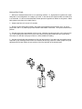
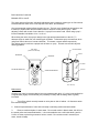
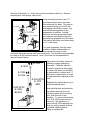
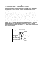
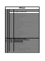
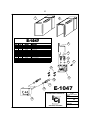
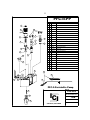
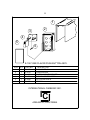
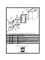
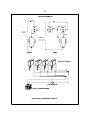
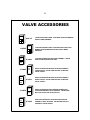
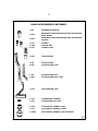
PCT - 2
INTERNATIONAL CARBONIC INC.
S
M
A
L
L
M
E
D
I
U
M
L
A
R
G
P
I
T
C
H
E
E
S
/
S
P
R
O
G
R
P USH
INTERNATIONAL CARBONIC INC.
ICI
ADELANTO, CALIFORNIA
VALVE BRIXING
AND
MAINTENANCE
MANUAL
TABLE OF CONTENTS
Page
Preface ................................................................................... 1
Brixing .................................................................................... 2-3
Maintenance ........................................................................... 3
Refurbishing ........................................................................... 4
Disassembly and Inspection ................................................... 4-6
Valve History .......................................................................... 7-8
Exploded Views
PFC-II ..................................................................... 9-10
E1047 Quick Release............................................. 11
PFC-II-PP ............................................................... 12
E1067 ..................................................................... 13
E1071 ..................................................................... 14
E1074 ..................................................................... 15
VALVE SCHEMATIC.............................................. 16
VALVE ACCESSORIES ......................................... 17
INTERNATIONAL CARBONIC INC.
VALVE ASSEMBLIES REPAIR
AND
REFURBISHING MANUAL
The purpose of this manual will be to assist the service
technician to identify, diagnose, disassemble, replace
or repair defective parts, reassemble and test all
valves manufactured by I.C.I.
For Further technical information please call 800 854-1177
CONGRATULATIONS: You now own one of the finest and most versatile valves on the market. With
minimal care, get ready for years of a consistent and perfect flow.
BRIX INSTRUCTIONS
1. Make sure carbonator/water flow is in an operating condition, i.e., high-pressure regulators set, water
and power on and refrigeration in a ready to go mode. In the case of juice systems make sure water flow
is un-restricted. It is also recommended that a water pressure regulator be utilized on all systems. Water
bath systems must have an ice bank formed.
2. Adjust water flow to 6 ounces in 5 seconds.
3. Remove nozzle (twist and pull down), then insert syrup separator through nozzle, be it “S” type or
plastic tube, and on ¼” plastic syrup outlet located inside hidden nozzle area. Then press nozzle back in
position.
4. Actuate valve until syrup separator is full of syrup. Hold brix cup close enough to valve outlet to form
“S” on the flexible plastic tube so as to prevent any water following the flexible tube into syrup section.
This formed “S” will also hold syrup in tube for a more reliable brix reading.
5. Actuate valve allowing the soda water to flow into large section of cup and syrup into smaller section.
Adjust the syrup metering pin/flow-control as necessary to secure a proper brix. When proper brix syrup
adjustments have been made, the two sections of the cup should fill to the desired ration.
Brix Instructions Continued
BRIXING PFC-II VALVE
The water and syrup flows are individually adjusted by their respective metering pin or flow-controls.
Located under the valve cover on the top rear of the valve, see illustration.
One recommended method utilizes the ratio brix cup. The brix cup is divided into two sections, one
to hold up to 9 parts water and the smaller section to hold one or two parts of syrup. When
adjusting a flavor with a ratio of more than 9 to 1 syrup 2 line must be used. When using syrup 2
line the waterside is doubled to 18 to 1 vs. 9 to 1.
When facing the valve, the syrup is always to the right and the water/soda is to the left. To
decrease syrup or water flow, turn metering pin clockwise. To decrease syrup or water flow, when
using flow control valves turn counter-clockwise. To increase, reverse rotation respectively.
The ultimate goal is to achieve a proper ratio of water vs. syrup. This ratio can and will vary with
differing products.
TOP VIEW
(valve cover removed)
18 PARTS/WATER
SYRUP
DECREASE
INCREASE
SYRUP 1
WATER METERING PIN
SYRUP 2
SYRUP METERING PIN
18 to 1 Brix Cup
Maintenance:
Cleaning your valve is recommended to insure a constant quality drink. If a valve is not sanitized on
a regular basis (nightly recommended), the possibility of foamy and off-tasting drinks is greatly
increased.
1.
Turn off key switch normally located on valve plate or side of cabinet. Or disconnect tower
from electrical supply.
2. Clean all exposed areas of valve with mild soap or sanitizing solution and warm water.
3.
Remove nozzle and place in warm water. Do not soak nozzle in bleach water, this will turn
the nozzle yellow and cause deterioration. It is recommended to use a soft bristle brush, part No.
S-1064, to clean any hard to get areas of valve or nozzle. Do not soak nozzle in extremely hot
water, nozzle will warp.
REFURBISHING:
The purpose of this section will be to assist the service technician to identify, diagnose,
disassemble, replace or repair defective parts, reassemble and test the valve.
DISASSEMBLY AND INSPECTION:
All valves from the FT-II through the PFC-II utilize the same valve covers.
You should, at this time inspect the valve cover for blemishes, scratches,
etc., then remove, exposing electrical and mechanical parts. It is
suggested that any valve cover other than new looking be replaced.
SERIAL NUMBER
TAG
IDENTIFY: Valves will normally have a serialized
name plate on the underside of the valve body
which identifies the valve. If this valve
identification is missing, we can visually identify
the valve by use of individual explode views.
INTERNATIONAL CARBONIC INC.
ADELANTO, CALIFORNIA
MODEL
PFC-II
C-122621
VOLTS 24VAC CYCLE 60 WATTS 20
MAX. 250
PRESSURE TEST
100
WORKING
CONFORMS
TO
ANSI/UL
STD. 73
NSF.
C-122621
INTERNATIONAL CARBONIC INC.
VALVE BOTTOM
VIEW
Possible Leak Area
Possible Leak Area
Possible Leak Area
Possible Leak Area
Possible Leak Area
Possible Leak Area
Once we have identified the valve, visually
inspect for obvious defects. Look for telltale
rust paths or areas, these areas normally
suggest the probability of a past leak, also
look for broken or misused items. The most
probable areas to look for leaks are shown in
above illustrations.
Remove all electrical, i.e., coils, wires and sub-miniature switch (s). Remove
actuating arm, leaf springs, and nozzle.
E-527 STEM
E-730 PLUNGER
E-531 GASKETS
Using external pressure or an I.C.I.
manufactured test stand, test valve
(less electrical) for leaks. This can be
accomplished using air or CO2 and
submerging valve body in water. Any
leak will become apparent by the
appearance of bubbles. Another
method is by using pressurized water
as a medium and visually looking for
this water being leaked out of the valve.
This method would be used when using
an I.C.I. test stand.
If no leak is apparent, then the valve
should be further disassembled, i.e.,
stem should be turned counter
clockwise which will remove stem from valve body. This should be accomplished
by using an E-685 solenoid wrench. Note: Pliers are not recommended to
remove solenoid stems.
E-1005
E-1004
E-1005
E-1004
E-520 WITH
E-1013
RED
E-520 WITH
E-1008
BLACK
Upon removal of stem, access is
gained to plunger and spring
assembly. Particular attention
should be directed to the plunger
to make sure there is no swelling
or deterioration of rubber seat. If
distortion or deterioration is noted,
plunger should be replaced at this
time.
Separate bins should be set up to
accommodate all parts.
Now that electrical and solenoids
have been removed, the only
remaining parts will be metering
pins, flow controls or flow
washers. To remove these items,
four (4) E-1005 screws must be
removed. This allows you to
remove the E-1004 retaining ring.
Now, by pulling upward, remove
individual metering device.
Place in separate bin.
5
It is recommended that all “O” rings be changed on any R & R.
Individual parts must be thoroughly cleaned, and if necessary, further disassembly
may be required to remove “O” rings. Example - see exploded view PFC-II on
metering pin.
If during pressure test bubbles are detected or water is apparent, then it must be
determined whether the valve body is the cause or whether the leak is caused by
an “O” ring. If it is determined that the leak is attributed to a cracked valve body,
then follow the above disassembly procedure, isolating defective valve body.
Note: If valve body is with in warranty return for replacement. Once all parts are
thoroughly cleaned and “O” rings replaced, reassembly can be accomplished.
It must be noted that all I.C.I. valves will accommodate metering pins, flow controls or
flow washers. Also, all I.C.I. valves will accommodate non-carbonated or carbonated
products. All I.C.I. valves are easily retrofitable to dual applications, i.e., addition of
small actuating arm that will actuate soda or water coil only. Refer to electrical
schematic to accommodate the dual feature. All I.C.I. Valves can be equipped with a
Quick Disconnect feature.
(VALVE COVER, COILS AND
STEMS, AND PLUNGERS REMOVED)
Decrease
Increase
Water Metering
Pin
Water Plunger Seat
Syrup Plunger Seat
Syrup Metering Pin
Water
Front
Syrup
6
VALVE HISTORY
E-160-A
DIFFUSER
E-201
NOZZLE
FT VALVE: Our first molded valve with large coils, Plungers, and
housings. Utilized the E-201 nozzle and E-160A diffuser. Discontinued
as a standard about 1978.
FT-II Valve: 1978, The first molded valve that utilized small coils,
plunger and housings. This valve differed from the FT also in the fact
that metering was accomplished by working from the top of the valve.
Also, this valve could use metering pins or flow controls. It still
utilized the E-201 nozzle and E-160A diffuser.
E-501-FF
NOZZLE
E-401
NOZZLE
E-401-FF
NOZZLE
E-401
NOZZLE
FT-II-FF Valve: 1983, The first valve that completely omitted the E160A diffuser. All Parts excluding the valve E-559-FF body and E-501FF nozzle were the same as the previous FT-II valve. The new E-501FF nozzle was of a two piece construction. An inner core was
machined from Delrin with an ABS outer jacket. This fast flow valve
utilized a stainless steel syrup outlet tube, E-571-FF, to diffuse the
syrup. Flow rate maximum 3 ounces per second.
PF Valve: 1984, Basically the same as the FT-II-FF except in a
standard flow configuration. The major change was the introduction
of a molded one-piece nozzle, E-401. The E-401 nozzle has an outlet
hole that is approximately 7/16” in diameter. This valve, with the
exception of the valve body E-459, nozzle E-401 and syrup outlet tube
E-471, use the same parts as the FT-II and FT-II-FF.
PF-FFV Valve: 1984, This valve was made in the likeness of the PF with
larger orifices to handle the greater volume. All parts with the
exception of the nozzle E-401-FF, syrup outlet E-471-S, and the valve
body E-459-FF are the same as the PF. The nozzle is made in a molded
one-piece construction with a 5/8” diameter outlet.
Flow rate
maximum 3 ounces per second.
PF-2-PB Valve: April 1989, This two-flavor valve was developed to
accommodate locations where it is impossible to install a larger unit
but another flavor is in demand. This valve will fit on any valve plate
that previously used a PF series valve. This valve utilized all parts that
were used on previous valves. Metering is accomplished from the
bottom and can only be performed by the use of metering pins. The
valve body, E-591, uses the E-401 nozzle. Special syrup outlets, two E595 are used. Also an E-1061 push button assembly is used as a
standard. This valve was designed as a standard flow valve only.
11/20/02
7
VALVE HISTORY PAGE 2
E-301
E-471-FF
E-581-FF
PFC Valve: January 1990, This valve used all the same
parts as the FT-II, FT-II-FF, PF and PF-FF, with the
exception of the E-359 valve body, E-301 nozzle and E471 syrup outlet.
The E-359 valve body cavity is
approximately 5/8” deep. The PFC nozzle will work on
the PF valve and visa versa. The only difference is that
there is no “O” ring groove.
Problem when these
nozzles are soaked in bleach or some cleaning agents
a small portion of the plastic erodes and the nozzle will
not stay in place during operation. This valve was our
first valve that was convertible, i.e., as a standard the
flow rate will be 1.5 ounce per second.
With the
change of a nozzle the flow rate can be up to 3.0 ounce
per second.
PFC-FF Valve: January 1990, The PFC-FF valve nozzle,
E-301-FF will not work on the PF-FF valve due to the
difference in the height of the interior cavity of the
body.
The E-359-FF body has a cavity depth of
approximately ½”. The PFC-FF syrup outlet tube, E471-FF can be used as a replacement for all syrup
outlet tubes. Flow rate 3.0 ounce per second.
PFC-II Valve: March 1993, The PFC-II valve is like all
I.C.I. Prfct Flow series valves, i.e., it will flow as a
standard or fast flow by changing the nozzle and
metering.
It uses all the same parts as its
predecessors. It can be converted to dual valve simply
by adding a dual kit. It can be metered by metering
pins. Flow controls or flow washers. The E-581 or E581-FF nozzles are different from their predecessors in
that they are of a twist lock configuration. The nozzle
for both fast flow and standard utilize the E-102 “O”
ring. The valve body, E-580 or E-580-FF (fast Flow), arc
configured to accommodate the twist lock nozzle. The
flow rate will be 1.5 ounce per second to 3.0 ounce.
PFC-II-B Valve: March 1997, The PFC-II valve nozzle
and nozzle cavity is made out of a black or smoked
plastic. Nozzle designation E-581-B standard and E581-FF-B fast flow. The valve body designation E-580B.
E-472-J
JUICE
DIFFUSER
E-472-J DIFFUSER: September 2002, The diffuser was
designed to promote almost perfect diffusion on all
juice valves. This diffuser is used on a standard juice
valve. The standard juice valve must have the E-471FF removed to implement the E-472-J diffuser.
11/20/02
8
9
16
1
10
2
11
3
12
4
9
13
1
9
10
5
14
15
6
10
30
7
31
14
15
8
32
17
14
19
18
33
12
34
20
35
21
22
17
23
24
29
36
23
25
26
27
INTERNATIONAL CARBONIC INC.
28
ICI
ADELANTO, CALIFORNIA
TITLE
PFC-II VALVE
DATE
12/18/98
DRN. BY
CHK. BY
APPR. BY
GLW
9
PFC-II
SYM QTY
1
2
2
2
2
3
4
2
5
2
6
1
7
2
8
2
9
4
10
2
11
2
12
2
13
2
14
1
15
1
16
1
17
2
18
2
19
2
20
1
21
1
22
1
23
1
24
***
25
1
26
1
27
1
28
1
***
29
***
30
***
31
***
***
32
***
***
33
***
34
***
***
35
***
***
36
***
***
PART NO. DESCRIPTION
E-623
NUT, SOLENOID
E-525
E-739
E-527
E-456
E-730
E-531
E-1005
E-1004
E-135
E-134
E-520
E-1008
E-1013
E-554-A
E-385
E-162
E-137
E-240
E-358
E-157
E-188
E-157-A
E-580-P
E-471-FF
E-102
E-581
E-581-FF
E-258
E-1024
E-1003
E-1010
E-1022
E-1023
E-1002
E-1006
E-1011
E-1007
E-1012
E-1016
COIL, W/SHIELD, SOLENOID, 24 VAC
FLUX PLATE
STEM, SOLENOID VALVE
ESCUTCHEON PLATE (1/2 PLATE)
PLUNGER & SPRING ASSEMBLY
GASKET, SOLENOID STEM
SCREW, RETAINER
RETAINER, S.S.
METERING PIN
"O" RING, METERING PIN
METERING PIN ADAPTOR ASSY, INCLUDES SYM 11, 12, & 13
"O" RING, SODA ADAPTOR
"O" RING, SYRUP ADAPTOR
CAP, COVERALL, SHORT
TUBING, INLET ASSY., 1/4" HOSE, S.S. 90 DEGREE
SCREW, TAP TIGHT
"O" RING, TUBE INLET
1/2 SCREW
ARM, ACTUATING
SWITCH, SUB MINIATURE
SPRING, W/INSULATOR PAD
SWITCH, SUB MINIATURE, DUAL (OPTIONAL)
VALVE BODY, WITH DRIVE PINS
SYRUP OUTLET TUBE
"O" RING, NOZZLE
NOZZLE, TWIST LOCK
NOZZLE, TWIST LOCK, FAST FLOW
ARM, ACTUATING, DUAL, LONG (OPTIONAL)
FLOW WASHER ADAPTER
HOUSING, W/SODA DECAL
HOUSING, W/SYRUP DECAL
FLOW WASHER, STANDARD FLOW
FLOW WASHER, FAST FLOW
ADJUSTING SCREW, W/"O" RING
SPRING, SODA
SPRING, SYRUP
PISTON & CYLINDER, SODA, (MATCHED SET)
PISTON & CYLINDER, SYRUP, (MATCHED SET)
"O" RING, BOTTOM SEALING
OPTIONAL, SPECIFY
10
1
2
E-1047
SYM
QTY
PART NO.
1
2
3
4
5
6
7
8
9
10
11
12
1
1
1
4
2
2
2
4
1
4
2
1
1
1
E-1045
E-1046
E-1040
E-186
E-1038
E-1039
E-240
A-48
E-1037
E-137
E-1043
E-1042
E-1041
E-1044
3
DESCRIPTION
COVERALL CAP
COVERALL CAP, FOR PCT/PUSH BUTTON
WIRE, LOCK
STOP PIN, (SWITCH PIN)
SCREW, SHUT OFF
"O" RING, SHUT OFF SCREW, 2-007
SCREW, INLET LOCKING
4
10-32 X 3/8 RD HD SCREW
BLOCK, MOUNTING
"O" RING, TUBE INLET, 2-010
COLLET
5
BLOCK, VALVE MOUNT
MOUNTING BLOCK ASSEMBLY ITEMS 3,4,5,6,7, & 9
VALVE BLOCK ASSEMBLY ITEMS 10, 11 & 12
7
6
NOTE: ITEM 8 PRIOR TO 1998 8-32 X 3/8 CAD RD HD SCREW
8
10
11
10
E-1047
INTERNATIONAL CARBONIC INC.
12
9
ICI
ADELANTO, CALIFORNIA
TITLE
E-1047
QUICK RELEASE VALVE MOUNT
DATE
DRN. BY
CHK. BY
APPR. BY
7/1/99
GLW
11
PFC-II-PP
SYM QTY
1
2
3
6
4
8
7
5
9
10
12
11
13
14
15
13
16
PART NO.
DESCRIPTION
1
1
E-623
NUT, SOLENOID
2
1
E-525
COIL, W/SHIELD, SOLENOID, 24 VAC
3
4
E-1005
SCREW, RETAINER
4
1
E-739
FLUX PLATE
5
1
E-527
STEM, SOLENOID VALVE
6
2
E-1004
RETAINER, S.S.
7
1
E-135
METERING PIN
8
1
E-1024-M
9
1
E-134
"O" RING, METERING PIN
10
1
E-1013
"O" RING, SYRUP ADAPTOR
ADAPTER, FLO WASHER, MODIFIED
11
1
E-730
PLUNGER & SPRING ASSEMBLY
12
1
E-520
METERING PIN ADAPTOR ASSY, INCLUDES SYM 7,9, & 12
13
2
E-531
GASKET, SOLENOID STEM
14
1
S-1162-A
15
1
E-1008
16
1
E-580
BODY, PFC-II, TWIST LOCK
17
1
E-157
SUBMINIATURE SWITCH
FLANGE PLUG
"O" RING, SODA ADAPTOR
18
1
E-188
19
1
E-471-FF
SPRING AND INSULATOR PAD
20
1
E-102
21
1
E-581
NOZZLE, TWIST LOCK
22
1
E-690
WIRE ASSEMBLY CONSISTS OF E-691 & E-692
23
1
E-691
MALE WIRE ASSEMBLY ONLY
24
1
E-692
FEMALE WIRE ASSEMBLY ONLY
SYRUP OUTLET TUBE
"O" RING, NOZZLE
22
23
17
18
24
PFC-II-Peristaltic Pump
INTERNATIONAL CARBONIC INC.
19
20
21
ICI
ADELANTO, CALIFORNIA
TITLE
PFC-II-PP
DATE
2/27/01 REVISED 9/27/01
DRN. BY
CHK. BY
APPR. BY
GLW
12
1
2
3
4
5
6
E-1067 ONE FLAVOR PUSH BUTTON ASSY.
SYM
1
2
3
4
5
6
QTY
1
1
1
1
1
1
PART NO.
E-1066
E-1072
E-1063
E-157
E-1068
E-1070
DESCRIPTION
CAP, COVER ALL
CONTROL BOX
SWITCH MOUNTING PLATE
SUB MINIATURE SWITCH
ACTUATING PLATE
SPRING
INTERNATIONAL CARBONIC INC.
ICI
ADELANTO, CALIFORNIA
13
1
2
3
4
5
6
E-1071 ONE FLAVOR PUSH BUTTON ASSY.
SYM
1
2
3
4
5
6
QTY
1
1
1
1
1
1
1
PART NO.
E-1066
E-1072
E-1063
E-157
E-1064
E-1070
E-1073
DESCRIPTION
CAP, COVER ALL
CONTROL BOX
SWITCH MOUNTING PLATE
SUB MINIATURE SWITCH
ACTUATING PLATE
SPRING
SWITCH AND ACTUATING ASSY., ITEMS 3,4,5, & 6
INTERNATIONAL CARBONIC INC.
ICI
ADELANTO, CALIFORNIA
14
1
2
3
4
7
PUSH
HERE
DUAL
PUSH
HERE
6
5
7
E-1074 SINGLE FLAVOR DUAL PUSH BUTTON ASSY.
SYM
1
2
3
4
5
6
7
QTY
1
1
2
1
1
2
2
PART NO.
E-1066
E-1072
E-1063
E-157
E-157A
E-1070
E-1068
DESCRIPTION
CAP, COVER ALL
CONTROL BOX
SWITCH MOUNTING PLATE
SUB MINIATURE SWITCH
ACTUATING PLATE
SPRING
ACTUATING PLATE
INTERNATIONAL CARBONIC INC.
ICI
ADELANTO, CALIFORNIA
15
VALVE SCHEMATIC
BLACK
RED
C
BLUE
C
NO
NO
NC
NC
WHITE
C
NO
NC
24 VOLT
WHITE
YELLOW
24 VOLT
SYRUP
WATER
SYRUP
WATER
SINGLE
DUAL
24 VOLT VALVES
KEY SWITCH
24 VOLT TRANSFORMER
ELECTRICAL SCHEMATIC 24 VOLT
16
VALVE ACCESSORIES
PCT-1T
S
P
R
M L
O
S
G
/
PCT-1T
3 PORTION CONTROL TIMER. AVAILABLE CAPACITOR MEMORY,
SPECIFY WHEN ORDERING.
S
PCT-2T
PCT-2T
S M
L
L
S
/
S
P
R
O
G
PUSH
HERE
E-1061
4 PORTION CONTROL TIMER. AVAILABLE WITH CAPACITOR
MEMORY, WITH INTERROGATIVE LED, SPECIFY WHEN
ORDERING.
2 FLAVOR PUSH BUTTON ACTUATOR ASSEMBLY. CAN BE
USED ON TWO FLAVOR VALVE ONLY.
PUSH
HERE
E-1067
PUSH
HERE
DECAL
AREA
E-1071
PUSH
HERE
SINGLE FLAVOR PUSH BUTTON ACTUATOR ASSEMBLY,
LARGE BUTTON. CAN BE USED WITH Q.R. OR NON Q.R.
VALVE, SPECIFY.
SINGLE FLAVOR PUSH BUTTON ACTUATOR ASSEMBLY,
SMALL BUTTON. CAN BE USED WITH Q.R. OR NON Q.R.
VALVE, SPECIFY.
PUSH
HERE
E-1074
PUSH
HERE
PUSH
HERE
PUSH
HERE
E-1075
SINGLE FLAVOR WITH DUAL FEATURE PUSH BUTTON
ACTUATOR ASSEMBLY, SMALL BUTTONS. CAN BE USED
WITH Q.R. OR NON Q.R. VALVE, SPECIFY.
SODA ONLY/WATER ONLY PUSH BUTTON ACTUATOR
ASSEMBLY, SMALL BUTTONS. CAN BE USED WITH Q.R.
OR NON Q.R. VALVE SPECIFY.
17
VALVE ACCESSORIES CONTINUED
E-520
METERING PIN ADAPTOR
E-520-J
METERING PIN ADAPTOR USED FOR JUICE APPLICATIONS,
HEAVY BAUME.
E-520-I
METERING PIN ADAPTOR USED FOR JUICE APPLICATIONS,
ISOTONIC.
E-730
PLUNGER
E-730D
PLUNGER, DIET
E-730J
PLUNGER, JUICE
E-472-J
JUICE DIFFUSER
E-358
ACTUATING ARM
E-358L
ACTUATING ARM, LONG
E-258
ACTUATING ARM, DUAL
E-258L
ACTUATING ARM, DUAL, LONG
E-357P
ACTUATING ARM, PUSH
E-1022
FLOW WASHER, STANDARD
E-1023
FLOW WASHER, FAST FLOW
E-1009
FLOW CONTROL ASSEMBLY, SODA
E-1014
FLOW CONTROL ASSEMBLY, SYRUP
E-1009FF
FLOW CONTROL ASSEMBLY, FAST FLOW,SODA
PUSH
12/97
REVISED
9/02
18