1
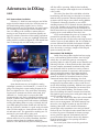
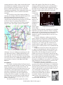
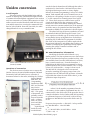
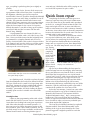
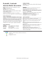
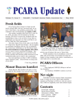
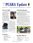
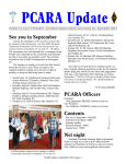
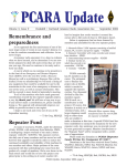
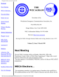
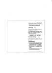
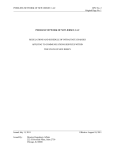
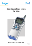
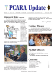
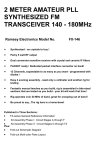
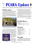
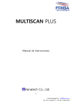
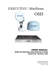
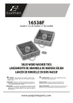
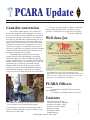
PCARA Update
Volume 10, Issue 3
Peekskill / Cortlandt Amateur Radio Association Inc.
Consider conversion
Ever wonder what happens to old commercial
grade radio equipment? Something that was “state of
the art” at one time becomes available for a fraction of
its original cost on-line or at hamfests. At our April 5th
meeting, Bob, N2CBH will be demonstrating how to repurpose rock-bound legacy commercial gear for amateur use. Bob will show us how to convert VHF-Hi and
UHF HTs to amateur service, through the use of new
crystals and a couple of tweaks. This could be developed into a club project of modifying a bunch of surplus
commercial HTs and mobile radios to amateur use for
emergency preparedness. Let’s talk!
PCARA has taken a club table at the Orange
County Amateur Radio Club Hamfest, on Saturday
March 28, 2009 at the Town of Wallkill Community
Center, in Middletown, NY. For further details visit the
OCARC website at http://www.ocarc-ny.org/. Take this
opportunity to get a jump on your shack’s Spring
cleaning! Make room for all the new gear you’ll be
getting as a result of the windfall from the 2009 Economic Stimulus Package! Bring along any stuff that
you’re interested in selling and put it on the club table.
March 2009
Our next meeting is March 1, 2009 at 3:00 PM at
Hudson Valley Hospital Center. As always, ALL are
welcome! I look forward to seeing each of you there.
- 73 de Greg, KB2CQE
Well done Joe
Joe WA2MCR just received this certificate from CQ
Magazine for the 2008 World Wide 160 Meter DX Contest,
where Joe won “1st place single operator low power SSB
New York, #12 United States, #1 2nd area.”
PCARA Officers
President:
Greg Appleyard, KB2CQE, kb2cqe at arrl.net
Vice President:
Joe Calabrese, WA2MCR; wa2mcr at arrl.net
Contents
Special conversion edition!
Consider conversion - KB2CQE
Adventures in DXing - N2KZ
Uniden conversion - NM9J
If you manage to sell some of your stuff, all we ask is
Quick Icom repair
that you consider donating a couple of dollars to help
WorldRadio online
offset the cost of the table.
Stamps jump up
PCARA Update, March 2009, page 1
Bob N2CBH, Joe WA2MCR and Ray W2CH in conversation
at the club table during the 2008 OCARC Hamfest.
1
2
5
6
7
7
Adventures in DXing –
N2KZ
DTV Conversion Confusion
February 17, 2009 has come and gone and all the
major television stations in the New York City area are
still broadcasting analog signals. Due to a heavyhanded request by our new President, the grand switchoff of analog TV broadcasting has been delayed until
June 12. Adding to the confusion, stations who are
moving to new frequencies to broadcast digitally can
apply for a further extension of their analog operations.
With FCC approval, you may see ‘nightlight’ broadcasts
telling viewers to switch to digital for a full month from
June 13 through July 12. Will analog ever end?
Channel 22 WWLP Springfield, MA switched
to all-digital on February 17.
Some broadcasters are not eligible for analog
‘nightlight’ operation. Local channels 7, 11 and 13 are
going to be using their current analog frequencies for
their new digital service. They won’t have old analog
frequencies to transmit on! On the other hand, NYC
channels 2, 4, 5 and 9 may be seen on their VHF
frequencies into July. These ‘nightlight’ broadcasts will
provide TV DXers with a unique one-time-only opportunity for E-skip viewing loaded with stations continually
sending IDs making them very easy to identify. Did you
ever think analog broadcasts would end with the best
DX test of all time? ‘Random’ is a good word to describe
what TV DXers might see. Some stations will be on the
air and some won’t. The potential for catching new TV
stations for your totals will be quite good.
When the analog world finally ceases on July 12,
all that will be left to see will be Canadians, Mexicans
and rare stations from the Caribbean and South
America. A few American low-powered analog stations
will also still be operating. With the band suddenly
empty, I can’t imagine what might be seen! It should be
a new world!
The end of low-band (56 to 88 MHz) television
broadcasting will also bring new freedom to six meter
amateur radio operations. Monster QRO operators on
six meters will no longer worry about causing QRM to
TV Channels 2 through 6 because no one will be
watching anymore! As TV channels become abandoned,
one by one, another type of activity is already being
seen: pirate television! Members of the Worldwide TVFM DX Association are reporting clandestine broadcasts
popping up in several markets across the U.S.A.
Never underestimate the power of six meters! The
potential for sporadic skip is always alive. E-skip,
meteors, auroras and even the moon can bring in exotic
catches. Listen to 50.098 MHz for CW, 50.110 MHz for
overseas USB and 50.125 MHz for domestic USB DX.
You never know when the band might light up. When it
does, the activity is exciting! (I might reach 100 grid
squares someday after all!)
Determined FM Hobbyist
Dobbs Ferry lawyer Marc Sophos has been trying
to be a self-sustaining FM broadcaster since his high
school days. He started his quest as a teenager by
providing audio for cable TV public access channels and
tinkering with Part 15 home broadcast kits. Marc built
his own complete automated broadcast facility in his
attic bedroom while he worked at a variety of metro
area broadcast stations for experience and sustenance.
Years of saving his pennies, fund-raising and dealmaking culminated in 1991 when Marc finally was
granted an official FCC broadcast license for a noncommercial station based in Ossining, New York.
Marc spent long hours and all his money to build
an impressive broadcast studio on the second floor of
an old office building in Ossining. Without tower space
for his two-bay Shively FM antenna, he mounted it on
the roof of the studio building. This became a fatal
flaw! The building also housed a music school and his
FM signals began creating havoc with guitar amps and
radios in nearby local stores.
It was a sad retreat when Marc had to disassemble
all his work in the office building. He found compromise in a new arrangement: The WDFH antenna was
moved to a new higher location up atop the hills of
Ossining. Marc built a self-contained automation
system right at the transmitter tower and got himself
back on the air. The higher location meant that he had
to reduce his power to maintain his former coverage
area to gain FCC approval. Unfortunately, his lowpower broadcasts were hard to hear at any distance
from his antenna due to close spacing with other
stations on 90.3 MHz.
For several years, Marc received a great boost
PCARA Update, March 2009, page 2
working with Mercy College. Marc provided his license
and transmission equipment. Mercy provided studio
space and legions of broadcast students. The two
parties worked hand-in-hand to create memorable
community programming. This arrangement came to an
end and Marc had to revert to another scaled-back
operation.
The clouds have now cleared again and Marc is
enjoying new sunlight. WDFH was granted approval to
move their antenna from Ossining down to
Pleasantville and raise power to 53 watts. This new
central location and much stronger signal now provides
a wide coverage area serving a large portion of
Westchester County. WDFH’s local-oriented programming is eclectic and original, produced entirely by
FCC service area for WDFH, 90.3MHz FM.
volunteers. If you are looking for something new and
very different to listen to, WDFH might become your
New Year’s gift. For more information, look at http://
www.wdfh.org or tune in to 90.3 FM. The little station
once known as the voice of Dobbs Ferry High School is
now the home of America’s most Determined FM
Hobbyist!
AT Sprint II
Last month, I mentioned that I had begun experimentation with another QRP kit. This time, it was an AT
Sprint II designed by Steve Weber KD1JV. This selfcontained battery powered four band transceiver is an
extraordinary concise lightweight design specifically
intended for backpackers and mountain toppers.
Powered by AAA batteries, the unit weighs nearly
nothing. The ATS II is capable of operating on 20, 30,
40 and 80 meters CW and features a tight band pass
filter of about 500 Hz and a built-in keyer for a CW
paddle. It is quite a rig.
The unit is squeezed into a plastic box whose
halves slide together. This allows for easy battery
changing and band switching. Your operating band is
determined by exchanging small rectangular boards
that slide into two sockets on the main board. The ATS
II produces a hefty signal of about five watts with
minimal
current draw.
I found a
few issues with
this transceiver. You
must be very
careful exchanging band
modules to
avoid the
AT Sprint II CW transceiver.
horror of gray
smoke! Align
your pins exactly or bear the consequences! I found the
band filter very tight for casual use. Unless a replying
station is close to your frequency you simply won’t hear
them! There is a provision for RIT, but you must remember to cancel its operation before you move on to
another station.
Frequency adjustment, sending speed and frequency readout are all achieved by manipulating four
delicate-looking red pushbuttons that stick out through
the plastic box. This seemed fragile to me. To move up
in frequency, you would toggle one switch then use
another switch to toggle down in frequency. It would
have been nicer if this operation were consolidated into
one switch.
Navigation of functions takes a little getting used
to. Again, by manipulating the onboard switches, you
can change frequency and have it read back to you in
Morse Code; you can change the speed of your CW
paddle and even record a message or put the unit into
beacon mode repeating a message time and again. Each
one of these features is reached by holding down a
button and waiting for the correct prompt to be heard
through your headphones in a sequence. I found myself
often turning the rig on and off just to get back to the
default frequencies or state of operation.
The ATS II is obviously geared for advanced CW
operators with a flair for the outdoors. It is reminiscent
of Dave Benson’s Small Wonder Labs series of rigs but
marketed and packaged in an entirely different way. As
a more casual operator, I prefer Dave’s SWL series but
you certainly have to admire Steve’s
compact and light design. The ATS II
has now been refined with an entirely
new model. Check out all of Steve’s
work at: http://kd1jv.qrpradio.com/.
Until next month, best of 73s and
dit dit de N2KZ ‘The Old Goat.’
PCARA Update, March 2009, page 3
Uniden conversion
A real bargain
This story begins with the PCARA bring and buy
auction in January. Bob, N2CBH had brought a bunch
of commercial radiotelephone equipment to the auction
and I was attracted to a Uniden UHF transceiver. A little
online research revealed that Bob’s AMU 250 was a 25
watt mobile transceiver covering the commercial UHF
band of 450-470 MHz. Next time I met Bob, the radio
changed hands for a very reasonable sum.
Uniden AMU 250 UHF FM transceiver as received
from Bob, N2CBH.
Questions of conversion
The obvious course of action was to convert the
Uniden down to the 440-450 MHz amateur FM band.
Fortunately, Bob had handed over a collection of
documents related to the radio, including the “Uniden
Service Manual
AMU 250”, the
“Programming
Instructions AMU
250” and “Preliminary Service
Information AMU
250”. This group
of documents was
probably worth a
lot more than the
radio – without
them, no conversion would have
been possible.
A quick check
inside the radio
revealed that it
was the deluxe 8-channel model. Although the radio is
synthesized, it dates back to 1982 and does not have
any high-tech microprocessors or a fancy display.
Instead, the channel programming is ‘stored’ in a diode
matrix. Each transmit and receive channel has a set of
16 diodes in a SIL package. Diodes are cut for a logical
“1” or left connected to channel-ground for a logical
“0”. These diode-arrays are soldered onto a pair of
circuit cards that fit into edge connectors on the
transceiver’s main circuit board. Rotating the channel
switch causes the common cathode line of the appropriate diode array to be grounded and the binary data is
then made available to the synthesizer’s divider inputs.
The phase lock loop frequency synthesizer is based
on a Motorola MC145152P integrated circuit. I had
some experience with this type of circuitry back in 1983
at Bury Radio Society in England where we had been
modifying UK 27 MHz FM CB equipment for 29 MHz
FM. Some of the inexpensive CB radios employed the
Motorola MC145106 IC, and shifting the frequency was
a matter of modifying the synthesizer’s binary inputs,
retuning the voltage-controlled oscillator and repeaking the RF circuits.
We want information, information!
Modifying the Uniden radio followed a very
similar pattern. The first requirement was to find a data
sheet for the Motorola frequency synthesizer chip – this
was available from Freescale Semiconductor’s web site,
http://www.freescale.com. From the data sheet, I
learned that the MC145152 is programmed by sixteen
parallel inputs for the N and A counters. The ÷N range
is from 3 to 1023 and the ÷A range is from 0 to 63.
The MC145152 is designed to drive an external
prescaler, extending its frequency range from a few
megahertz into the VHF and UHF spectrum. A formula
is provided that relates the total divide value NT to the
synthesizer input frequencies:
…where N is the number programmed into the
÷N counter, A is the number programmed into the ÷A
counter and P is the divide ratio of the prescaler. Here is
a sample calculation for the Uniden AMU 250 operating
on a transmit frequency of 450.0125, with its in-loop
oscillator on 320 MHz and a prescaler divide ratio (P)
of 40:
Frequency into prescaler = 450.0125 – in-loop oscillator, 320.000 MHz = 130.0125 MHz
so
NT = 130.0125 MHz / 0.0125 MHz = 10401
= (260 × 40) + 1
PCARA Update, March 2009, page 4
For N=260 and A=1 the binary pattern for the
phase lock loop’s ÷N and ÷A inputs is as follows:
8 ÷N
0
5 ÷A 0
100000100
000001
…where a “1” means the diode in that position is
cut and “0” means the diode remains in place.
Would it work?
My guess was that all that was needed to convert
the Uniden down to 440 MHz would be to change the
patterns in the diode arrays then re-peak the tuned
circuits. The first thing to do was to draw up a table
showing the binary patterns needed to cover the
amateur band. In the 29 MHz FM CB conversions, I had
written a little BASIC program to do this job and ran it
on my Commodore PET, with output on a dot matrix
printer. A quarter century later, we have more powerful
tools available, and I prepared the new table of binary
patterns for 440–450 MHz using Microsoft Excel.
For an initial test, I chose a transmit frequency
from the table that would need as few diodes as possible:
8 ÷N 0
5 ÷A 0
TX 447.8750 MHz 011111111 011110
TX 447.8875 MHz 011111111 011111 «
TX 447.9000 MHz 011111111 100000
The diagram shows how one of the 16-diode
arrays would be cut (‘x’) for a transmit frequency of
447.8875 MHz:
Inside the AMU 250. The two channel boards containing
the diode arrays for frequency programming are
indicated by white arrows.
More useful frequencies
Having proved the point that the radio would tune
down to 440 MHz, it was time to program some useful
frequencies into it, using the diode arrays. The first
circuit board already had four diode arrays soldered on,
and I took a careful look at whether they could be
reused. I was trying to change as few of the diodes as
possible. Here’s how I reprogrammed the first channel
for the KB2CQE repeater:
8 ÷N
0 5 ÷A 0
Channel 1 RX 463.925 MHz 011110101 000010
change to RX 449.925 MHz 011011001 000010
Channel 1 TX 468.925 MHz 100101001
change to TX 444.925 MHz 011111001
Common-cathode diode array as used in the AMU 250.
This particular frequency, 447.8875 MHz, only
needs two diodes in positions N8 and A5 to program
the radio. I tack-soldered the two diodes onto an empty
channel position on the circuit board, connected the
transceiver to a dummy load and switched on.
The Service Manual provides instructions for
adjusting the voltage-controlled oscillator (VCO) – this
was simply a matter of adjusting a trimmer capacitor
inside the VCO shield cover while monitoring the
voltage on a nearby test-point. I had already checked
the various test voltages while the radio was operating
on one of the commercial channels, and it did not take
long to adjust to the correct value on 447.8875 MHz.
This was followed by peaking of the transmitter’s RF
circuitry according to the service manual.
In a short time, RF output power began to appear
on the power meter and the red “TX” LED lit up. The
transmitter could easily supply 25 watts on this new
frequency.
100010
100010
Only three changes were needed on the first diode
array and only four on the second, shown above in
bold. Sounds pretty simple! But it was more complicated in practice. First I had to completely unsolder the
two 18-pin SIL packages from the circuit board, using
HA047 16-diode array from Uniden AMU 250.
my trusty solder sucker. The diode legs then had to be
folded out of the way or rewired to a previously cut
position. Finally, each diode array had to be soldered
back onto the circuit board again. It was evident that I
wasn’t the first person to do this, as the circuit board
showed signs of previous channel changes, with tracks
lifting off the substrate and the board warping with the
heat. There is no wiggle-room between the SIL pack-
PCARA Update, March 2009, page 5
ages, everything is packed together just as tightly as
possible.
After a couple of tries, the two diode arrays were
reprogrammed and soldered into place. I repeated the
RF alignment, obtaining good power output on
444.925 MHz. However, operation through the KB2CQE
repeater requires one more thing, a transmit PL tone of
179.9Hz. This particular Uniden radio features an 8channel CTCSS tone generator, with a separate trimpot
for each channel. I had to reconnect a wire link, then
adjust the first trimpot for the correct PL frequency.
Shortly afterwards, I was able to bring up the repeater
on 449.925 MHz and had a contact with the man
himself, Greg, KB2CQE.
I reprogrammed the next channel for Bob’s repeater on 448.725 MHz, with a 107.2 Hz PL tone. This
time, I chose two diode arrays that had originally been
programmed for a simplex transmit and receive frequency of 463.925 MHz. This needed a lot more diodes
to be changed, and it took a while to get all the connections soldered. But after a few corrections, the radio
came up on the correct frequency.
Uniden AMU 250 after conversion to 440 MHz, with
new panel lamp in place.
As a finishing touch, I decided to replace the panel
lamp that illuminates the back of the channel indicator.
The type of bulb used is a small 12 volt pea lamp with
wire leads. I managed to find a suitable bulb at Radio
Shack, disguised as a red snap-in “12 VDC Lamp
Assembly”, part number 272-0332. Pulling the plastic
assembly apart revealed a suitable wire-ended bulb
within.
Nostalgia time
I must say that programming radios with a diode
matrix like the Uniden’s is not as easy as I remembered.
I must have been looking back at my past experiences
with older radios through rose-tinted spectacles. If
there was a need to change frequencies again, or add
more channels, quite a lot of work is involved. The 18pin diode arrays are no longer available, and the multichannel circuit boards are showing distinct signs of
wear and tear. I think this radio will be staying on our
two local UHF repeaters for quite a while.
- NM9J
Quick Icom repair
Completing the Uniden conversion gave me a
chance to repair my trusty old Icom IC-3200A transceiver. This Icom was my first mobile radio purchased
in the U.S.A., costing $479 back in March 1986. This
large sum bought a 25 watt, 2 meter/440 MHz oneband-at-a-time transceiver, with 10 memory channels.
At the time, Icom radios stood out from the competition
because they included the PL-encode unit. This was an
optional extra for other manufacturers.
The radio was mounted in two different vehicles
over a period of thirteen years, after which it saw
service indoors for monitoring the local UHF repeaters.
The LCD panel was backlit with three incandescent
lamps, and over a period of years, these lamps failed
one by one. The third lamp burned out a few weeks
ago, leaving
the LCD panel
completely
black. The
panel could be
read in daylight, but at
night I had to
Icom IC-3200A with unlit liquid crystal
shine a flashdisplay. Is it switched on?
light to check
the frequency.
My first try at disassembling the front panel to
reach the lamps was not encouraging. After removing
the top and bottom covers from the radio, it was clear
that behind the front panel were two circuit boards,
“Logic A” and “Logic B”, with a large collection of multiway cables connecting the top Logic B board to the
main transceiver body. The Logic B board also held a
lithium coin cell that backed up the CPU memory.
Disconnecting this battery would likely wipe out all the
memories. I put the radio back together again while I
considered the problem for a few more weeks.
Before the next attempt, I carried out some online
research and found a copy of the IC-3200A/E Service
Manual in PDF format at “The Repeater Builder’s
Technical Information Page”, http://www.repeaterbuilder.com. This is an excellent site for all things
related to repeaters and amateur FM activities. Remember to check here when you have any technical questions about surplus FM equipment.
The Icom Service Manual contained an exploded
diagram entitled “Front Panel Disassembly” and a
drawing of the Logic A circuit board layout. These
pictures suggested it might be possible to reach the
PCARA Update, March 2009, page 6
front panel lamps by removing items from the front of
the radio, rather than by starting from the rear of the
front panel and removing layer after layer of circuit
boards.
The diagrams were correct! The order of removal
was as follows… disconnect power from the radio,
remove top and bottom covers, remove four screws
holding plastic front panel to metal sub-chassis. Pull off
three front panel knobs and unscrew the front bezel off
the microphone connector. Pull the plastic front panel
straight off the radio – taking care that the eleven push
buttons don’t fall out of the plastic panel. This reveals
the liquid crystal display mounted on the front-facing
side of the Logic A board. (See photo.)
IC-3200A with plastic front panel removed.
By removing a black rubber cover and straightening three metal clips, the entire LCD assembly can be
lifted straight off the circuit board, revealing three
green-colored dial lamps (DS1, DS2 and DS3) mounted
directly on the Logic A circuit board.
new bulbs is critical because they have to fit into three
cutouts in the plastic light guide that surrounds the LCD
assembly.
Refitting the LCD assembly and powering up the
radio proved
that the new
lamps were
now lit and
the liquid
crystal display
was still
functioning
correctly. The
front panel
was reassembled, then
the top and
bottom covers
were replaced.
The radio was
as good as
Icom IC-3200A afer LCD backight
new!
was repaired.
In these
times of economic uncertainty, it is well worth conserving resources by keeping an older radio running for a
while longer. There are a few features missing from
these older radios – they might not have many memories, but they also have no noisy cooling fan, no complicated menus to set up and no wide-band front end,
wide open to cross-modulation. A good bargain all
round.
- NM9J
WorldRadio online
The first two issues of WorldRadio Online —
February and March 2009 — are now posted on CQ
Magazine’s web site. To download and view the issues,
go to the CQ home page at http://www.cq-amateurradio.com and click on the “World Radio Online” box.
These are large Acrobat PDF files, 12-13 MB in size.
After removing the LCD assembly, the Logic A circuit board is
visible, with three green backlight lamps (first one arrowed).
New Lamps for Old
These lamps are specified in the Icom parts list as
“HRS-7219A-G40”, which is a 12 volt ‘grain of wheat’
bulb with twin wire connections. I found an equivalent
at Radio Shack, part number 272-1092, a #7219 Micro
Lamp rated at 12 volts, 60 milliamps, with a wire
terminal base.
The lamps on the Icom circuit board were covered
with thin, green silicone rubber caps. The transparent
caps change the display color from amber to green. I
transferred the rubber caps to the new bulbs, cut the
wire leads to the old bulbs then soldered the new bulbs
in their place on the circuit board. Positioning of the
Stamps jump up
The price of a first class stamp will increase 2
cents from 42 cents to 44 cents on Monday May 11.
“Forever Stamps” intended for mailing 1-ounce letters
at any time, can still be used after the price change,
without the need for any additional postage. While the
44 cent stamp will be sufficient for a one ounce letter,
the cost of a two ounce letter will also increase by 2
cents to 61 cents. Postcards will increase by 1 cent to
28 cents. The International rate increases from 94 to 98
cents for a 1-ounce air-mail letter (Canada and Mexico
are less.) Remember to keep your QSL Manager
stocked with envelopes having sufficient postage.
PCARA Update, March 2009, page 7
Peekskill / Cortlandt
Amateur Radio Association
PCARA Calendar
Sun Feb 1: PCARA meeting. Hudson Valley Hospital
Center, 3:00 p.m.
Mail: PCARA, PO Box 146, Crompond, NY 10517
E-Mail: [email protected]
Web site: http://www.pcara.org
Hamfests
PCARA Update Editor: Malcolm Pritchard, NM9J
E-mail: NM9J @ arrl.net
Newsletter contributions are always very welcome!
Archive: http://home.computer.net/~pcara/newslett.htm
PCARA Information
PCARA is a Non-Profit Community Service Organization. PCARA meetings take place the first Sunday of
each month* at 3:00 p.m. in Dining Room B of the Hudson
Valley Hospital Center, Route 202, Cortlandt Manor, NY
10567. Drive round behind the main hospital building and
enter from the rear (look for the oxygen tanks). Talk-in is
available on the 146.67 repeater. *Apart from holidays.
PCARA Repeaters
W2NYW:
146.67 MHz -0.6, PL 156.7Hz
KB2CQE:
449.925MHz -5.0, PL 179.9Hz
(IRLP node: 4214)
N2CBH:
448.725MHz -5.0, PL 107.2Hz
Sun Mar 8: LIMARC Long Island Hamfair & Electronics
Show, Levittown Hall, Hicksville, NY. 9:00 a.m.
Sat Mar 28: Orange County ARC Spring Hamfest, Town of
Walkill Community Center, 2 Wes Warren Drive, Middletown,
NY. 8:00 a.m. (Club Table)
Sat Apr 4: Splitrock ARA Hamfest, Roxbury Senior Center,
72 Eyland Ave, Succasunna, NJ. 8:00 a.m.
Sun Apr 26: Mt Beacon ARC Hamfest, Tymor Park,
LaGrangeville, NY. 9:00 a.m. (Club Table)
VE Test Sessions
Mar 1: Yonkers ARC, Yonkers PD, 1st Precinct, E Grassy Sprain
Rd, 8:30 a.m. Contact D. Calabrese, (914) 667-0587.
Mar 12: WECA, Westchester Cnty Fire Trg Center, 4 Dana Rd.,
Valhalla, NY. 7:00 p.m. Contact Stanley Rothman (914) 8313258.
Mar 16: Columbia Univ VE Team, 2960 Broadway, 115
Havemeyer Hall, New York NY. 6:30 p.m. Contact Alan Croswell,
(212) 854-3754.
Mar 20: Bergen ARA, Westwood Regional HS, 701 Ridgewood
Rd, Washington Twnshp, NJ. 7:00 p.m. Contact Donald C
Younger, (201) 265-6583.
Mar 28: Orange County ARC, Town of Wallkill Community
Center, 2 Wes Warren Rd, Middletown NY. 8:30 a.m.
Apr 25: PEARL, Mahopac Public Library, 668 Rt 6, Mahopac NY.
10:00 a.m. Contact NM9J.
Peekskill / Cortlandt Amateur Radio Association Inc.
PO Box 146
Crompond, NY 10517
PCARA Update, March 2009, page 8