1
Dive Rite
Regulator Service Manual
Warning
• This manual is only to be used as a guide
for trained Regulator technician.
Possession of this guide does not qualify
any individual in the service of Dive Rite
Breathing Systems. Only qualified Dive Rite
Dealers can Service Dive Rite Products.
Improper servicing can lead to serious
injury or death.
Table of Contents
Dive Rite Dive Regulator Service Manual
Section 1
RG1205 First Stage Disassembly........................... Page 2
RG1205 service Kit................................................ Page 13
Assemble RG1205 ................................................. Page 14
RG1210 Second Stage............................................ Page 25
RG1210 Service Kit................................................ Page 36
Assemble RG1210................................................... Page37
RG1215 Octo Disassembly..................................... Page 47
RG1215 Service Kit................................................ Page 53
Assemble RG1215 Octo.......................................... Page 54
Tuning Dive Rite Regulators................................... Page 59
Troubleshooting....................................................... Page 62
Section 2
RG2010 Adjustable Balanced Second Stage
Addendum
RG2010 Second Stage Disassembly....................... Page 1
RG2010 Service Kit.................................................Page 15
Assemble RG2010 Second Stage.............................Page 16
Tuning.......................................................................Page 28
Diagrams
RG1205 First stage
RG1210 Adjustable Second Stage
RG1215 Alternate/Octo
RG2010 Adjustable Balanced Second Stage
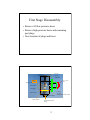
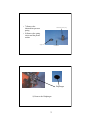
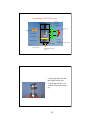
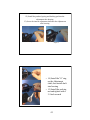
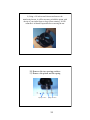
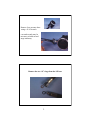
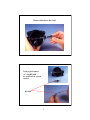
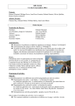
First Stage Disassembly
• Remove All low-pressure hoses
• Remove high-pressure hoses and remaining
port plugs
• Note location of plugs and hoses
“O” ring
“O” ring
Inlet Filter
Spring
Din Lockdown
Screw
High pressure valve
Valve Lifter
Diaphragm
Hand wheel
Thrust washer
Plastic Washer
Spring Carrier
Intermediate pressure
spring
2
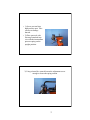
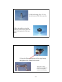
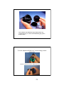
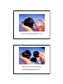
“O” ring
located inside turret retainer
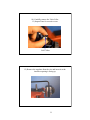
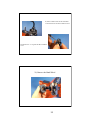
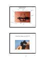
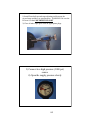
• 1) Screw port tool into
high-pressure port. Take
care not to damage
threads.
• 2) Place port tool with
first stage attached into
vise with the intermediate
pressure spring on the
upright position.
3) Using a 6mm Hex wrench loosen the adjustment screw
enough to lessen the spring tension
3
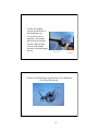
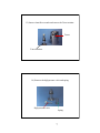
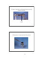
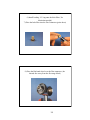
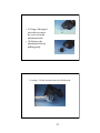
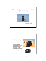
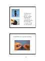
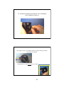
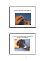
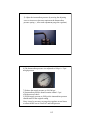
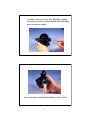
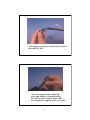
• 4) Place the Spanner
wrench into the holes of
the Diaphragm cap
• 5) Loosen the cap by
applying a firm steady
pressure on the housing
• Caution: Rapid jerking
can cause the spanner
wrench to slip and damage
the cap
Spanner wrench
Diaphragm cap
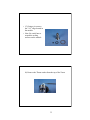
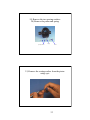
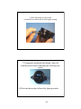
6) Unscrew the Diaphragm cap and remove the Adjustment
screw from the housing
Diaphragm Cap
Adjustment screw
4
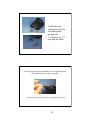
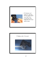
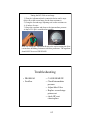
• 7) Remove the
intermediate pressure
spring
• 8) Remove the spring
carrier and the plastic
washer
Intermediate pressure spring
Spring Carrier
Plastic washer
Diaphragm
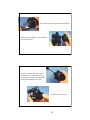
9) Remove the Diaphragm
5
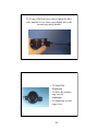
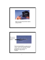
10) Carefully remove the Valve Lifter
11) Inspect Parts for excessive wear
Valve Lifter
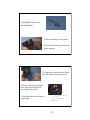
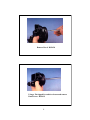
12) Remove the regulator from the vise and invert it so the
6mm hex opening is facing up
6
13) Insert a 6mm Hex wrench and remove the Turret retainer
Turret
Turret Retainer
14 ) Remove the high pressure valve and spring
High pressure valve
Spring
7
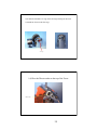
• 15) Using a pic remove
the 3 “O” rings located in
the module
• Note: Be careful not to
scratch the sealing
surfaces on the module
16) Remove the Thrust washer from the top of the Turret
8
17) Remove the Turret and corresponding large “o” ring
• 18) Using a Pic remove
the exterior “o” ring from
the Din Lockdown screw.
( If the yoke adapter is
attached unscrew the
yoke. This “o” ring is
located in the track
surrounding the High
Pressure Inlet
9
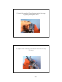
19) Insert a 6mm wrench into the Tank Inlet
Loosen and remove the Din Lockdown Screw
20) Remove the “o” ring from the Din Lockdown
screw
21) Remove the Hand Wheel
10
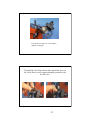
22) Using a 19mm Socket wrench loosen and remove the Din
Connector and Saddle
Saddle
23) Remove the “o” ring located on the Din connector
11
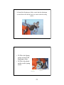
• 24) Carefully remove
the cone shaped filter
and “o” ring from the
interior of the Din
Connector
• Change all the “o”
rings on the port plugs
and all hoses
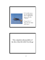
This completes disassembly of
the Dive Rite RG1200 First Stage
12
A) All the old parts that are to be replaced as designated
by the new rebuild kit and should be packaged
B) The remaining parts should be cleaned in a solution
designated for Nitrox cleaning
C) The following lubricants should be used in the reassembling
of the First Stage. Christo-Lube, Krytox or any one of a number
of products available for this purpose that are Nitrox compatible
RG1261 First Stage service kit
•
•
•
•
•
•
•
•
RG1230 Diaphragm
RG1231 “O” ring
RG1232 “O” ring
RG1233 “O” ring
RG1234 H.P. Seat
RG1235 “O” ring
RG1236 “O” ring
RG1237 Thrust
washer
•
•
•
•
•
•
RG1238 “O”ring
RG1239 “O” ring
RG1240 Inlet filter
RG1241 “O” ring
RG1242 “O” ring
RG1243 “O” ring
13
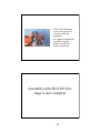
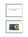
Assembling the RG1200 first stage
“O” ring
“O” ring
Inlet Filter
Spring
Din Lockdown
Screw
High pressure valve
Valve Lifter
Diaphragm
Hand wheel
Thrust washer
Plastic Washer
Spring Carrier
“O” ring
located inside turret retainer
Intermediate pressure
spring
• 1) Screw the port tool into
the High Pressure port
• 2) Place the tool in a vise
with the Turret side facing
up
14
3) After lubricating, place “O” ring
into the bottom of the Din connector
4) Place the saddle over the Din
connector ( Be careful to place the
curved side against the first stage
block
5) Screw the Din connector into the first stage housing
and tighten with a 19mm Socket wrench
Apply One (1) drop
of Locktite to the threads
before screwing DIN
connector into Housing
15
6) Install backing “O” ring onto the Inlet filter ( No
lubrication needed)
7) Place the Inlet filter into the Din Connector (point down)
8) Place the Din hand wheel over the Din connector ( the
threads face away from the first stage block)
16
9) Lubricate and install “O” ring on the top of the din wheel lockdown screw
lubricate and install “O” ring on the bottom of the din wheel lockdown screw
10) Install the Din wheel lockdown screw into the Din connector and
tighten with a 6mm hex wrench
11) Turn the First stage so the Turret side is up
17
12) Lubricate and install “O” ring on the first stage housing for the turret
13) Install the Turret on the first stage
“O” ring #
14) Place the Thrust washer on the top of the Turret
Thrust washer
18
Preparing the Turret retainer/ HP module for
installation
• 15) Lubricate and install “O”
ring inside the top of the Turret
Retainer
• 16) Lubricate and install “O”
ring on the turret retainer on
the surface just below the
threads
• 17) Lubricate and install “O”
ring on the base of the Turret
retainer
• 18) Place the spring on
the top of the Turret
retainer
• 19) Install the new HP
valve. Allow the stem to
pass through the center of
the spring and through
“O” ring
HP valve
spring
19
20) Install the completed Turret Retainer into the first stage
by passing it through the turret
21) Tighten with a 6mm hex wrench ( Be careful not to crimp
“O” ring )
20
22) Turn the first stage over so the balance
chamber is facing up
23) Install the valve lifter into the first stage block, press on
the Valve lifter to verify contact and spring resistance with
the HP valve
21
24) Install the Diaphragm ( Make certain that the diaphragm
is seated below the threads and is in contact with the seating
surface
• 25) Place the Spring
carrier on top of the
diaphragm center
• 26) Place the plastic
washer on the spring
carrier
Spring carrier
Plastic washer
22
27) Install the Adjusting screw ( two turns) into the
Diaphragm cap
28) Place the Intermediate pressure spring onto the spring
carrier
23
• 29) Place the diaphragm
cap over the spring and
screw the cap down
completely
• 30) Tighten the diaphragm
cap firmly using the
spanner wrench with
steady even pressure
Assembly of the RG1205 first
stage is now complete
24
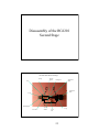
Disassembly of the RG1210
Second Stage
Dive Rite RG1200 second stage
Spacing
washer
Spring
Piston
Packing nut
Adjustment
Shaft
Adjustment
Knob
“o” ring
Inlet Nipple
Inlet Valve
Spacing
Washer
“o” ring
Lever
Arm
25
1) Remove the LP hose from the second stage using a 3/4
and11/16 wrenches
2) Remove the two “O” rings from the LP hose
26
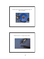
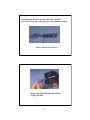
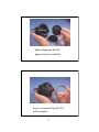
3) Using a 3/4 inch wrench loosen and the remove the Inlet Nipple
• 4) Unscrew the front
cover ( No tools
required)
• 5) Remove the retainer
ring
• 6) Remove the
diaphragm
Retainer
ring
Diaphragm
Front Cover
27
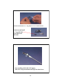
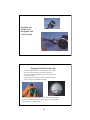
Current Models of the RG1200 no longer utilize Retainer ring
a 1218 Second stage cover and 1219 Metal Retaining ring replaces
the older models
7) Set the Adjustment Knob to its’ easiest setting (counter
clock-wise)
8) Remove the decal from the adjustment knob
28
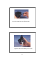
• 9) Using a flat tipped
screwdriver remove
the screw from the
adjustment knob
• 10) Remove the
adjustment knob by
pulling gently
11) using a 3/4 inch wrench remove the Packing nut
29
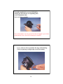
• 12) Remove the
adjustment shaft that
went through the
packing nut
• 13) Remove the “O”
ring from the shaft
14) Unscrew the interior adjustment screw with needle nose
pliers and remove the entire assembly
Clean and lubricate all the interior parts to the adjustment assembly
30
15) Insert the ERASER side of a #2 pencil against the LP
piston ( This will cause the piston to move into the housing.
The lever arm will lower, continue to press firmly until the
lever arm can be removed)
16) Remove the Lever Arm
31
17) Remove the adjustment housing, remove the “O”
ring from the housing
Remove this “O” ring
• 18) Using a 1/4 inch open
end wrench loosen and
remove the Stainless
locking nut. It will be
necessary to hold the
piston with the tip of your
index finger to keep it
from rotating. ( Note:
count the threads exposed
before removing the nut)
32
19) Remove the two spacing washers
20) Remove the piston and spring
Spacing washers
Spring
Piston
21) Remove the seating surface from the piston
using a pic
33
22) Cut the tie wrap that surrounds the mouthpiece
23) Remove the mouthpiece ( the exhaust tee
can now be removed
24) Use a small flat tipped screwdriver
CAREFULLY pry the exhaust tee loose
by using the small spaces provided under
the Inlet and Adjustment tube ports
25) Remove the exhaust tee
34
26) Remove the Exhaust valve by pulling
gently
Exhaust valve
The Dive Rite RG 1210 second
stage has now been completely
disassembled
35
A) All the old parts that are to be replaced as designated
by the new rebuild kit and should be packaged
B) The remaining parts should be cleaned in a solution
designated for Nitrox cleaning
C) The following lubricants should be used in the reassembling
of the First Stage. Christo-Lube, Krytox or any one of a number
of products available for this purpose that are Nitrox compatible
Service Kit RG1262 for the RG1210 adjustable
second stage
• RG1264 Low pressure
seat
• RG1255 “O” ring
• RG1263 SS orifice
• RG1266 Nylon Insert
Nut
• RG1257 “O” ring
• RG1258 “O” ring
• RG1267 Decal
36
Assembling the Dive Rite
RG1210 second stage
Spacing
washer
Spring
Piston
Packing nut
Adjustment
Shaft
Adjustment
Knob
“o” ring
Inlet Nipple
Inlet Valve
Spacing
Washer
“o” ring
Lever
Arm
1) Install the Exhaust valve RG1251
37
• 2) Lubricate and
install “O” ring
• RG1257 onto the
adjustment tube
• 3) Reinstall the
Adjustment tube into
the second stage
( remember to align
the collar properly)
4) Install the valve seat into the Piston
38
5) Place the spring over the piston
6) Install this assembly into the Inlet nipple opening
7) Temporarily install the Inlet Nipple ( this will
hold the piston in place and make the following step
easier)
8) Place the thin washer followed by Spacing washer
39
9) Install the Stainless nylon insert nut onto the
piston finger tight
Stainless nylon insert nut
10) Remove the inlet nipple
11) using the 1/4 wrench tighten the Stainless nylon insert nut
( tighten the nut the same # of threads that it was previously
installed with re: step18 in disassembly)
40
12) Install the pushrod, spring and backing pad into the
adjustment tube housing
13) Screw the interior adjustment shaft into the Adjustment
tube housing
Step #12
Step# 13
• 14) Install the”O” ring
on the Adjustment
shaft, then install shaft
into housing
• 15) Install the packing
nut and tighten with a
3/4 inch wrench
41
17) Install the lockdown the lockdown screw and tighten
with a flathead screwdriver
18) Using the eraser of a #2 pencil compress the piston to the point where
the washers are exposed.
19) Install the lever arm between the two washers
42
• 20) Lubricate and
install “O” ring onto
the Inlet nipple. Install
a new Inlet Valve
• 21) Install the Inlet
Nipple into the second
stage housing
22)Tighten with a 3/4 wrench
43
23) Using a flat head screw driver tighten the Inlet
valve until the Lever Arm is just slightly above the
second stage body threads
• 24) Install the
Diaphragm
• 25) Place the retainer
ring over the
diaphragm
• 26) Install the second
stage cover
44
27) Install the exhaust tee ( Be certain the
locking clips engage on both sides of the
housing
28) Install the mouthpiece and secure with a
tie wrap
45
29) Lubricate and install “O” rings and on the low pressure
hose. Install the hose into a LOW pressure port on the RG1200
First stage
Dive Rite RG1210 second stage
Spacing
washer
Spring
Piston
Packing nut
Adjustment
Shaft
Adjustment
Knob
“o” ring
Inlet Nipple
Inlet Valve
Spacing
Washer
“o” ring
Lever
Arm
46
Disassembling the RG1215
octopus
1) Remove the Low Pressure hose from the first stage using a 9/16 inch wrench
2) Remove the Low Pressure hose from the second stage using a 3/4 and 11/16 inch
wrenches
47
3) Remove the two “O” rings
from the LP hose
4) Using a 3/4 inch wrench remove the Inlet Nipple
remove the “O” ring from the Inlet Nipple
48
5) Unscrew the front cover ( no tools required)
6) Remove the retainer ring and diaphragm
7) Insert the eraser side of a #2 pencil against the LP Piston
{ This will Cause the Piston to move into the housing. The
Lever Arm will lower, continue to press firmly until the Lever
Arm can be removed)
8) Remove the Lever Arm
49
9) Using a 1/4 inch wrench loosen and remove the
stainless/nylon nut, it will be necessary to hold the piston with
the tip of your index finger to keep it from rotating NOTE:
count the # of threads exposed before removing the nut
10) Remove the two spacing washers
11) Remove the piston and the spring
Spacing washers
Spring and Piston
50
12) Remove the seating surface using a Pic
13) Cut the tie wrap that surrounds the mouthpiece
and remove the mouthpiece
51
• The exhaust tee can
now be removed
• 14) Use a small flat
tipped screw driver
and Carefully pry the
exhaust tee loose by
using the spaces
provided
15) Remove the Exhaust tee by pulling gently
The RG1215 octopus has now been completely disassembled
52
A) All the old parts that are to be replaced as designated
by the new rebuild kit and should be packaged
B) The remaining parts should be cleaned in a solution
designated for Nitrox cleaning
C) The following lubricants should be used in the reassembling
of the First Stage. Christo-Lube, Krytox or any one of a number
of products available for this purpose that are Nitrox compatible
RG1268 Octopus service kit
• 1) RG1264 Low
Pressure Seat
• 1 ) RG1255 “O” ring
• 1) RG1263 SSOrifice
• 1) RG1266 Nylon
insert nut
• 1) RG1260 “O” ring
53
Assembling the RG1215
Octopus
1) Install the Exhaust Valve
54
2) Install the Valve seat
into the piston
3) Place the spring over the piston
4) Install this assembly into the Inlet
Nipple opening
5) Temporarily install the Inlet Nipple
This will make the next step easier
6) Place the thin spacing washer
on the piston first followed by
the wide spacing washer
Thin spacing washer
7) Install the stainless nylon nut
finger tight
Wide spacing washer
Stainless nylon nut
55
8) remove the Inlet Nipple
9)Using the 1/4 inch wrench tighten the stainless
nylon nut (tighten the nylon nut the same # of
threads it was previously installed)
10) Using a # 2 pencil compress the the piston to the point
that the spacing washers are exposed
Install lever arm
11) Install the lever arm between the two spacing washers
56
12) Tighten with a 1/4 inch wrench
13) Using a flat head screwdriver turn
the inlet valve until the lever arm is just
slightly above the second stage cover
threads
14) Lubricate and install “O” ring onto the Inlet Nipple
15) Install the Inlet Nipple with Inlet valve # 1263 and “O” ring
Inlet valve
16 ) Tighten with a 3/4 inch wrench
57
17) Install the Diaphragm
18) Place the Retainer Ring on top of the Diaphragm
19 ) Install the second stage cover
hand tight
20 ) Install the Exhaust Tee
21) Install the mouthpiece and
secure with a tie wrap
58
22) Lubricate and install two “O”rings on the Low pressure
hose.
This completes assembly of the RG 1200 octopus
Tuning and adjusting the
Dive Rite RG1200 Regulator
59
1) Install Peter built second stage adjusting tool between the
second stage and the Low pressure hose. WARNING: Be sure the
LP hose is in the LOW PRESSURE PORT
2) Close all other open ports with the appropriate plugs
3) Connect to a high pressure (3000 psi)
source
4) Open the supply pressure slowly
60
5) Adjust the intermediate pressure by moving the adjusting
screw to increase or decrease tension on the Intermediate
pressure spring. ( After each adjustment purge the regulator)
6) The Intermediate pressure is to adjusted to 140 psi +/- 5psi
at high pressure
7) Reduce the supply pressure to 300-500 psi
8) Intermediate pressure should remain within 1-2 psi
of high pressure check
9) Reset supply pressure to 3000 psi the intermediate pressure
should return to the original setting
Note: it may be necessary to purge the regulator several times
to allow the HP seat to “break in” and hold pressure
61
Tuning the RG 1200 second stage
1) Turn the Adjustment knob counterclockwise until it stops
(this will set the second stage for the least resistance)
2) Using the Second stage adjusting tool set the resistance to
.6-.8 inches of water
3) Purge the regulator and observe the intermediate pressure.
A drop of 2-8 psi is considered acceptable
Note: By setting the Adjustment Knob to the easiest setting the diver
can increase breathing resistance to his/her preference. The regulator
should NOT be set to FREEFLOW
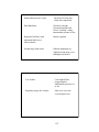
Troubleshooting
• PROBLEM
• Freeflow
• CAUSE/REMEDY
• Check Intermediate
pressure
• Adjust Inlet Valve
• Replace second stage
piston seat
• check HP seat
clean/replace
62
Intermediate pressure creeps
Hp Seat N/G,clean seat
inside first stage block
Hard Inhalation
Check lever height
Check adjustment knob
Check “cracking” setting
Intermediate pressure to low
Regulator freeflows when
adjustment knob set at
least resistance
Retune regulator
Second Stage leaks water
Exhaust diaphragm n/g
Tighten second stage cover
Mouthpiece defective
Low airflow
Cone shaped filter
clogged/replace
Intermediate pressure set
to low
Regulator purges low volume
Inlet valve set to low
Lever height to low
63
RG2010 Balanced
Second Stage
Service Manual
Warning
• This manual is only to be used as a guide
for trained Regulator technician.
Possession of this guide does not qualify
any individual in the service of Dive Rite
Breathing Systems. Only qualified Dive Rite
Dealers can Service Dive Rite Products.
Improper servicing can lead to serious
injury or death.
1
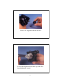
Remove Low pressure hose
using a 11/16 wrench
a second wrench may be
necessary to hold second
stage stationary
Remove the two “O” rings from the LP hose
2
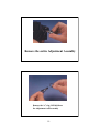
Unscrew Aluminum Ring Part # 1219
Remove Front Cover Part RG1218
Remove Diaphragm Part RG1252
3
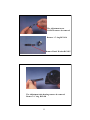
Carefully remove the Lever Arm RG1402 by pulling
the arm away from the Adjust tube RG1405 and lifting
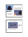
note: no tools are needed
Loosen the Inlet screw RG1410 utilizing a 11/16 wrench
4
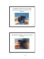
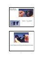
Remove Inlet Screw RG 1410
Using a pick remove
“o” ring RG1409
be careful not to scratch
surface
RG1409
5
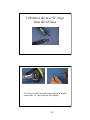
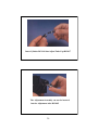
A Flat tipped screw driver will be needed to loosen
the orifice RG 1412
After loosening the orifice completely
use a 6mm Allen key to push the orifice
The Orifice will be returned to Dive Rite
The rebuild kit is supplied with a new Orifice
6
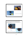
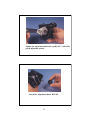
Remove the Inlet Tube RG1407 and the
Spring RG1403
LP seat not to
be removed or
reused.
The Inlet Tube RG1407 is to replaced in its
entirety. The LP Seat RG1408 is installed
permanently in the replacement.
RG1406 “O” rings are also
included.
7
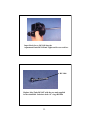
Remove Decal RG1420
Using a Flat tipped Screwdriver loosen and remove
Knob Screw RG1419
8
Remove the Adjustment Knob RG1418
Loosen the Adjustment knob tube cap with a flat
jawed adjustable wrench
9
Remove the entire Adjustment Assembly
Remove the “o” ring RG1404 from
the Adjustment tube assembly
10
The Adjustment screw
RG1414 can now be removed
Remove “o” ring RG 1416
Remove Plastic Washer RG1415
The Adjustment tube housing can now be removed
Remove “o” ring RG1404
11
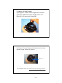
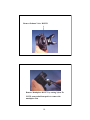
The Deflect tube RG1422 can now be removed take note of the
orientation before removal. Small opening faces the Diaphragm
Using needle nose pliers remove the Clip RG1422
12
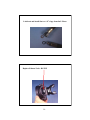
Remove Defector
Assembly RG1424
Remove “o” ring RG1423
Remove Exhaust tee RG1401 by gently pulling from the bottom
13
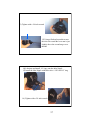
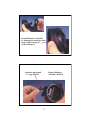
Remove Exhaust Valve RG1251
Remove Mouthpiece RG1273 by cutting Nylon Tie
NOTE: some technicians prefer to remove the
mouthpiece first
14
Warning! Only original Dive Rite Replacement parts are to
Be used in the servicing of the RG 2010 second Stage
A) All the old parts that are to be replaced are designated
in the new rebuild kit .Old parts should be packaged and returned
to Dive Rite
B) The remaining parts should be cleaned in a
solution designated for Nitrox cleaning
C) The following lubricants should be used in the assembly
of the First Stage. Christo-Lube, Krytox or any one of a number
of products available for this purpose that are Nitrox compatible
RG1425 Service Kit
Balanced Second Stage Rg1210
•
•
•
•
•
•
RG1404 “O” Ring
RG1406 “O” Ring
RG1408 LP Seat
RG1409 “O” Ring
RG1411 “O” Ring
RG1412 Orifice
• RG1415 Plastic
Washer
• RG1416 “O” Ring
• RG1420 Decal
• RG1421 Clip
• RG1423 “O” Ring
15
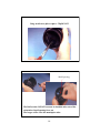
Lubricate and install the two “O” rings from the LP hose
Replace Exhaust Valve RG1251
16
Install Exhaust tee RG1401
by insuring the raised lip on the
body is under the groove
of the exhaust tee
Lubricate and install
“o” ring RG1423
Replace Deflector
Assembly RG1424
17
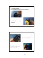
Using needle nose pliers replace Clip RG1422
Small opening
The Deflect tube RG1422 can now be installed take note of the
orientation. Small opening faces out
The larger orifice faces the mouthpiece tube.
18
Opening on Adjustment tube
assembly aligns with bottom
of the Deflect Tube RG1422
Lubricate and Install
“o” ring RG1404
Replace Plastic washer RG1415
Lubricate and
Install “o” ring
RG1404
Lubricate and Install “o” ring RG1416
19
Insert Cylinder RG1414 into Adjust Tube Cap RG1417
The Adjustment Assembly can now be inserted
into the Adjustment tube RG1405
20
Tighten the Adjustment knob tube cap RG1417 with a flat
jawed adjustable wrench
Install the Adjustment Knob RG1418
21
Insert Knob Screw RG1418 into the
Adjustment Knob RG1419and Tighten with a screwdriver
RG 1406
Replace Inlet Tube RG1407 with the new unit supplied
in the rebuild kit. Lubricate both “O” rings RG1406
22
Install Spring RG1403 onto the Inlet Tube RG1407
note: the narrow end of the spring is to be installed as shown
Narrow end towards LP seat
Replace the Inlet Tube RG1407 and the
Spring RG1403
23
Lubricate and Install new “o” ring RG1411 on New Orifice RG1412
Lubricate and install
“o” ring RG1409
onto Inlet screw
RG1410
After installing Orifice RG 1412 tighten
until valve seat protrudesfrom the tip of the Inlet Screw
24
Insert this assembly into the Adjustment tube
Tighten the Inlet screw utilizing a 11/16 wrench
25
Carefully install the Lever Arm RG1402 by
Placing the tabs into the corresponding holes
on the Adjustment tube
note: no tools are needed
Note: If the Orifice was not screwed into the inlet nipple as previously
mentioned the Lever Arm will be improperly installed
Lever Arm is to be set just below the edge of the housing.
Check by placing a straight edge across the housing.
26
Replace Diaphragm RG1252
Replace Front Cover RG1218
Replace Aluminum Ring RG1219
and hand tighten
27
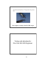
Install the Low
pressure hose
and tighten with
a 11/16 wrench
Tuning the RG 2010 second stage
1) Turn the Adjustment knob counterclockwise until it stops
(this will set the second stage for the least resistance)
2) Using the Second stage adjusting tool set the resistance to
.6-.8 inches of water
3) Purge the regulator and observe the intermediate pressure.
A drop of 2-8 psi is considered acceptable
Note: By setting the Adjustment Knob to the easiest setting the diver
can increase breathing resistance to his/her preference. The regulator
should NOT be set to FREEFLOW
28
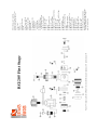
Parts 29 -31make up the Cold Water Conversion Kit these parts replace part 13 and reuse part 14
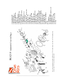
RG1205 First Stage
Yoke Assembly can be installed
to replace DIN Fitting Parts 1-6 are
necessary to replace parts33-39
1) Yoke Screw
2) Yoke
3) Dust Cover
4) RG1240 Inlet Filter
4-1) Clip
5) Yoke Connector Body
6) RG1241 “O” ring
7) DIN Connector saddle
8) First Stage Body
9) Valve Lifter
10) Diaphragm RG1230
11) Spring Carrier
12) Intermediate
Pressure Spring
13) Diaphragm Cap
14) Intermediate Pressure
Spring Adjustment Screw
15) RG1246 Port Plug HP
16) RG1231 ”O” ring
17) RG1232 “O”ring
18) Turret
19) RG1245 Port Plug LP
20) RG1233 “O” ring
21) RG1234 Valve Seat HP
22) High Pressure Valve return Spring
23) RG1235 “O” ring
24) RG1236 “O”ring
25) RG1237 Thrust Washer First Stage
26) RG1238 “O” ring
27) Turret retainer
28) RG1244 Plastic washer
29) Cold water Diaphragm Cap
30) Piston
31) Cold Water Diaphragm
32) Cold Water Diaphragm Cap
33) RG1239 “O” ring
34) DIN Connector Body
35) DIN Hand Wheel
36) RG1240 Inlet Filter
37) RG1241 “O” ring
38) DIN Lockdown Screw
39) RG1242 “O” ring
40) RG1243 “O”ring
41) Thrust Washer part discontinued
Newer model RG1205 first stages utilize
a thicker Diaphragm which no longer
need the Thrust washer
14X
5
4
12
11
15
1
2
16
17
18
19
7
6
20
8
9
On second stages made from late 2000 on, a 1218 second stage cover and a 1219 Retaining ring
replaces parts 7-10 (see photos in manual)
14
13
3
10
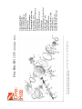
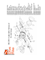
Dive Rite RG 1215 Alternate/ Octo
1) Second Stage Body
2) RG9320 Pull Tie
3) RG1250 Mouthpiece
4) RG1251 Exhaust Valve
5) Exhaust Tee
6) RG1252 Diaphragm
7) Diaphragm Retainer ring
8) Second stage Cover
9) Spring, Purge button Return
10) Purge Button
11) Main Spring valve Seat
12) Inlet Stem
12X) RG1264 Low Pressure Seat
13) RG1255 “O” ring
14) Inlet Nipple
14X) RG1263 Orifice
15) Spacing Washer, Thin
16) Demand Lever
17) Spacing washer, Fat
18) RG1266 Nylon Insert Nut
13
14
34
12
12X
11
1
15
2
16
17
18
32 33
21
22
7
23
6
24
20
25
8
19
26
9
27
28
29
On second stages made from late 2000 on, a 1218 second stage cover and a 1219 Retaining ring
replaces parts 7-10 (see photos in manual)
14X
5
4
3
34
RG1210 Adjustable Second Stage
10
30
1) Second stage body
2) RG9320 Pull tie
3) RG1250 Mouthpiece
4) RG1251 Exhaust valve
5) Exhaust Tee
6) RG1252 Diaphragm
7) Diaphragm Retainer ring
8) Second Stage Cover
9) Spring purge button return
10) Purge Button
11) Main Spring Valve Seat
12) Inlet valve Stem
12X) RG1264 Low Pressure seat
13) RG1255 “O” ring
14) Inlet Nipple
14X) RG1263 Orifice
15) Spacing Washer,thin
16) Demand lever
17) Spacing Washer,Fat
18) RG1266 Nylon Insert Nut
19) RG1257 “O” ring
20) Adjustment Housing
21) Interior Adjustment Screw
22)Adjustment Screw Spring
23) Adjustment Screw Button
24) Adjustment carrier
25) Adjustment Shaft
26) RG1258 “O” ring
this part is to installed on
part 25
27) Packing Nut
28) Adjustment Knob
29) Adjustment Knob lockdown screw
30) RG1267 Decal
31) Deflector “O”ring
32) Dive/Pre-dive Switch
33) Clip
14
5
13
12
4
19
1
3
11
2
18
10
17
16
31
15
30
6
28
20
7
21
11
22
8
29
RG2010 Adjustable balanced
Second stage
24
23
9
25
26
27
1) RG1400 Main Housing
2) RG1273 Pull Tie
3) RG1250 Mouthpiece
4) RG1251 Exhaust Valve
5) RG1401 Exhaust Tee
6) RG1402 Lever Arm
7) RG1252 Diaphragm
8) RG1218 Face Cover
9) RG1219 Face Ring
10) RG1403 Spring
11) RG1404 “O” ring
12) RG1405 Adjustment tube
13) RG1406 “O” ring
14) RG1407 Inlet Tube
15) RG1408 LP Seat
16) RG1409 “O” ring
17) RG 1410 Inlet Screw
18) RG1411 “O” ring
19) RG1412 Orifice
20) RG1414 Cylinder
21) RG1413 Adjustment Screw
22) RG1415 Plastic washer
23) RG1416 “O” ring
24) RG1417 Adjustment Tube
cap
25) RG1418 Adjustment Knob
26) RG1419 Knob Screw
27) RG1420 Decal
28) RG1421 Clip
29) RG1422 Deflector tube
30) RG1423 “O” ring
31) RG1424 Deflector