1
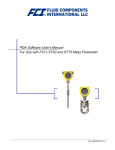
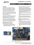
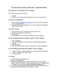
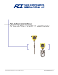
APEX 150
™
Service Manual
1 Introduction
This document applies to the proper
procedure and steps required to manually
install and replace APEX 2.8™ (2.8mm) and
APEX 150™ (1.5mm) terminals in the APEX
150 Hybrid Connector Family.
• When the terminal is correctly installed,
there will be a small click and some
tactile feedback.
• When the terminal is correctly installed,
there will be a small click and some
tactile feedback.
• Once all the terminals are inserted in
the correct position, then press the TPA
into the “final lock” position as shown
in figure 5. If the TPA will not move into
the final-lock position, verify that all
terminals are fully seated.
1.1 Reference
FCI Terminal Drawings:
J54009
J54011
C15004
C15005
FCI Connector Drawings:
K53001
K53002
Required Tools:
Small Needle Nose Pliers
Small Flat Blade Screw Driver
APEX 150 Service Tool (542416XX)
2 Terminal Insertion Instructions
2.1 Female Terminals
• Make sure TPA is in the “pre-lock”
position in the female housing. See
Figure 1.
verify the cavity does not have a seal
plug and verify the TPA is fully in the
pre-lock position (Figure 4).
FIGURE 2
• Once all the terminals are inserted in
the correct position, then press the TPA
into the “final lock” position as shown
in Figure 1. If the TPA will not move
into the final-lock position, verify that
all terminals are fully seated.
2.2 Male Terminals
• Make sure TPA is in the “pre-lock”
position in the female housing. See
Figures 5 and 6.
Pre-Lock
FIGURE 4
• Orient the male terminals correctly with
each terminal position opening in the
male connector assembly as shown in
Figure 3.
Pre-Lock
Final-Lock
Final-Lock
FIGURE 1
• Orient the female terminals correctly
with each terminal position opening in
the retainer of female connector
assembly as shown in Figure 2.
FIGURE 5
• Carefully insert the terminal into the
cavity opening. Only slight force should
be needed. If the force to install each
terminal seems high or the terminal
will not seat – Stop! Remove the
terminal, recheck its orientation, verify
the cavity does not have a seal plug,
and verify the TPA is fully in the prelock position.
3.1 Female Connector
3 Terminal Replacement
Instruction
FIGURE 3
• Carefully insert the terminal into the
cavity opening. If the force to install
each terminal seems high or the
terminal will not seat – Stop! Remove
the terminal, recheck its orientation,
• Insert a small flat blade screw driver in
the slot provided in the TPA and apply
pressure to “Bridge” area of connector
as shown in Figure 6.
• Gently “pry” or pivot the screw driver
thus sliding the TPA into the “Pre-Lock”
position. WARNING: Do not grab or
APEX 150
™
Service Manual
grip the Shorting Bar tabs if so
equipped. Tabs may be damaged
leading to a failure of the shorting
bar function.
terminal stays retained or seems
“stuck,” try reinserting the service tool.
• To attach a new terminal to the wire
see the appropriate APEX Terminal
Crimping Guide.
• With the TPA in the “pre-lock” position,
insert the tip of the Service Tool into
the service port for the terminal in be
removed/replaced. Use care to be sure
the service tool stays in the service
port track (Figure 11).
FIGURE 6
• With the TPA in the “pre-lock” position,
insert the tip of the Service Tool into
the service port of the terminal in be
removed/replaced (Figure 7). NOTE:
Care should be used so as to not insert
the service tool into the terminal
opening.
• Push the Service Tool until resistance is
felt. Carefully press harder until the
service tool moves slightly further into
the connector (this may be
accompanied by a small tactile
sensation). At this point the selected
terminal is ready to be removed.
• Gently pull the TPA into the “Pre-Lock”
position. The TPA should not be
removed from the connector.
WARNING: Care must be used so the
pliers do not slip out of the service
holes and damage any exposed
terminal blades or pinch the
operators hands.
FIGURE 8
3.1 Male Connector
Service Port
FIGURE 11
FIGURE 9
• Grip the TPA with a pair of serrated
needle nose pliers by using the
appropriate holes in the center of the
TPA (Figure 10).
• Push the Service Tool until resistance is
felt. Gently press harder until the
service tool moves slightly further into
the connector (this may be
accompanied by a small tactile
sensation).
• While maintaining pressure on the
service tool, the selected terminal may
be removed from the rear of the
connector by simply pulling it out by its
wire. NOTE: Terminal removal should
require only a gentle pulling force
applied to the wire. If the terminal
stays retained or seems “stuck”, try
reinserting the service tool.
Service Ports
FIGURE 7
• While maintaining pressure on the
service tool, the selected terminal may
be removed from the rear of the
connector by pulling it out by the wire.
To help maintain seal integrity, if
possible, pull the wire at a small angle
away from the connector center as
shown in Figure 8 (not required for
2.8mm terminals). NOTE: Terminal
removal should require only a gentle
pulling force applied to the wire. If the
FIGURE 10