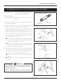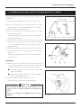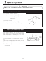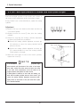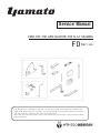
1
Service Manual
FEED-OFF-THE-ARM MACHINE FOR FLAT SEAMING
F D Series
This document is a simplified version of the ser vice manual. The adjustment methods and
similar information that are included in the sewing machine’
s instruction manual are omit ted.
Use this document together with the instruction manual.
Note that the tools and gauges used in this manual are special-order tools. Please purchase
them separately.
CONTENTS
1. How to use tools and gauges
1
1.1 Installing needle clamp
1
1.2 Height of needles
2
1.3 Adjusting back and forth moving amount of looper
1.4 Setting angle of looper
3
4
1.5 Adjusting right and left moving amount of looper
5
1.6 Timing of needle and looper
6
1.7 Distance between needle and looper
8
2.Special adjustment
2.1 Adjusting frame chip guard
2.2 Adjusting stitch unlocking spring
2.3 Left-and-right position of needle and stitch plate tongue
9
9
9
10
Note
This product is subject to change without notice. Due to such event, the contents of this manual may not match the
product in some regards. Every effort has gone into making this manual, nevertheless should you discover any mistakes
or missing information, please note that it may not always be possible for Yamato to correct those errors immediately.
1.How to use tools and gauges
ALWAYS turn OFF the motor switch and check that the motor stops before the work.
1.1 Installing needle clamp
Tools and gauges: Needle bar setting torque rod (0068375) ①
Standard torque: 2.0 N•m
Insert the needle bar setting torque rod ① into the hole on
the upper side of the needle bar ② , and tighten it until it
starts to bend.
①
②
2.0N ・ m
NOTE
Do not tighten with a torque higher than 2.0 N・m.
If you tighten with a torque higher than 2.0 N・m, the
diameter of the lower edge of the needle bar ② will expand, making the needle bar ② unusable.
Note that the lower edge of the needle bar ② does not
touch the top end of the needle clamp ③ .
③
Fig. 1-1
FD
1
1. How to use tools and gauges
1.2 Height of needles
Tools and gauges: Needle height test pin (0068370) ①
Needle height gauge (see table below) ②
Part No. of needle
height gauge
Needle
distance
Height of
needles
0068360
R
13.49 ㎜
0068563
S
12.70 ㎜
(1)Rotate the pulley to move the needle bar ③ to the
highest point.
(2)Insert the needle height test pin ① into the fourth hole
to the left of the needle clamp ④ .
(3)Remove the seal plug ⑤ .
(4)Loosen the screw ⑥ .
(5)Adjust so that the 13.49 mm (12.70 mm) section of the
needle height gauge② can enter smoothly with no clearance.
(6)Set the needle, and make sure that the needle and the
needle drop are parallel. (Fig. 1-4)
(7)Tighten the screw ⑥ .
(8)Install the seal plug ⑤ .
NOTE
④
①
②
Fig. 1-2
③
It is easy to check the parallelism of the needle and the
needle drop if you use the upper knife ⑦ , with the lateral
groove of the stitch plate as a reference. (Fig. 1-5)
If the left-and-right position of the needle is not
appropriate (center of the needle drop area), the sewing
cylinder must be adjusted.
(Refer to“2-3 Adjusting the sewing cylinder position”in
this manual.)
⑥
⑤
Fig. 1-3
⑦
Fig. 1-4
Fig. 1-5
FD
2
1. How to use tools and gauges
1.3 Adjusting back and forth moving amount of the looper
Tools and gauges
:L
ooper avoid gauge unit (0068371) ①
Offset box wrench (0099099) ⑥
Looper avoid gauge unit ①
Standard back and
forth moving amount: 2 .1 m m t o 2.4 m m (2.4 m m a t
shipment)
(1)Rotate the pulley to move the looper rocker shaft to
the rearmost position.
(2)Remove the looper cover spring support, and then
insert the looper avoid gauge unit ① into its hole.
(3)Press the bearing ③ forward so that the plunger ② is fully
pushed out, and then fix it with the screw ④ . (Fig. 1-7)
(4)Adjust so that when you rotate the pulley to move the
looper rocker shaft to the foremost position, end face
A of the bearing ③ comes between end faces B and C
of the plunger ② . (Fig. 1-8)
● If end face B of the plunger ② is aligned with end
face A of the bearing ③ , the back and forth moving
amount of the looper ⑤ is 2.1 mm.
● If end face C of the plunger ② is aligned with end
face A of the bearing ③ , the back and forth moving
amount of the looper is 2.4 mm.
(5)To perform adjustment, remove the sewing cylinder
cover (left), loosen the screw ⑥ at the front of the
looper avoid connecting rod with the offset box wrench
⑥ , and move the screw ⑥ up or down. (Fig. 1-9)
● Move up to shorten the back and forth moving
amount.
● Move down to lengthen the back and forth moving
amount.
Plunger ②
Bearing ③
Fig. 1-6
③
⑤
②
④
Fig. 1-7
A
2.1 ㎜
B
C
2.4 ㎜
Fig. 1-8
NOTE
After adjusting the back and forth moving amount of the
looper, be sure to check the front-and-rear position of
the needle and looper.
(Refer to“Adjusting the looper”in the instruction manual.)
⑦
⑥
Fig. 1-9
FD
3
1. How to use tools and gauges
1.4 Setting angle of looper
Tools and gauges: Looper angle gauge (0068368) ①
Standard setting angle: Face A is perpendicular to the
looper rocker shaft ② (Fig. 1-11)
(1) Insert the looper angle gauge ① into the inner wall in
which the feed bar of the sewing cylinder is positioned.
(2) Insert a screwdriver into the semicircular cutout section
B and press it against the right wall face, while also
making it contact the looper ③ .
(3) Loosen and adjust the screw ④ so that the looper ③ is
against the end face of the looper angle gauge ① with
no clearance.
①
③
B
Fig. 1-10
NOTE
After adjusting the looper setting angle, be sure to check
the front-and-rear position of the needle and looper.
(Refer to“Adjusting the looper”in the instruction manual.)
③
②
A
④
Fig. 1-11
FD
4
1. How to use tools and gauges
1.5 Adjusting the right and left moving amount of looper
Tools and gauges: Looper rocking movement gauge unit
(0068365) ①
Standard moving amount: 55°40′(54°40′to 56°40′)
(1)Remove the looper cover spring support, and then
insert section A of the gauge graduation into its hole.
(2)Tighten slightly with the screw ④ .
(3)Use the screw ⑤ of the needle guard (front) to install
the gauge pointer ③ .
The gauge pointer ③ should be as close as possible to
the gauge graduation ② .
(4)Fix with the screw ④ so that when you rotate the
pulley to move the looper ⑥ to the rightmost position,
0° on the gauge graduation ② is aligned with the
gauge pointer ③ .
(5)Check the graduation of the gauge pointer ③ when you
rotate the pulley to move the looper ⑥ to the leftmost
position.
Adjust if the gauge pointer is not within the standard (54°
40' to 56°40').
Looper rocking movement gauge unit ①
Looper rocking
movement gauge pointer ③
A
Looper rocking movement gauge graduation ②
Fig. 1-12
⑥
⑤
Adjustment
(1)Remove the top cover (front) of the frame and the top
cover (front) gasket, loosen the lock nut (left-hand
thread) ⑦ , and adjust with the adjusting screw ⑧ .
● Rotate the adjusting screw ⑧ clockwise to decrease
the moving amount.
● Rotate the adjusting screw ⑧ counterclockwise to
increase the moving amount.
(2)After adjustment, tighten the lock nut ⑦ .
②
③
④
Fig. 1-13
Increase
Decrease
⑧
Check the right and left moving amount again.
NOTE
After adjusting the right and left moving amount of the
looper, be sure to check the timing of the needle and
looper.
(Refer to“1.6 Timing of the Needle and Looper”in this
manual.)
⑦
Fig. 1-14
FD
5
1. How to use tools and gauges
1.6 Timing of needle and looper
Tools and gauges: L
ooper and needle synchronizing gauge
unit (0068361) ①
Standard timing : T
he needle and looper are synchronized
at a position 3.97 mm from where the
needle starts its upward movement from
the lowest point.
(1)Rotate the pulley to move the needle bar to the lowest
point.
(2)Loosen the adjusting screw ⑤ .
(3)Insert the needle setting block ② to the adjusting
screw ⑤ .
(4)Position so that the adjusting screw ⑥ comes above the
needle bar, and tighten the needle setting block ② .
(5)Rotate the adjusting screw ⑥ until the clearance with
the top of the needle bar ⑬ is 3.97 mm.
Looper and needle synchronizing gauge unit ①
Synchronizing gauge rod ④
Needle setting
block ②
3.97 ㎜
Looper clamp and height gauge ③
Fig. 1-15
⑦
⑤
②
⑥
NOTE
The thickness of the looper clamp and height gauge ③ is
3.97 mm.
You can use this section to measure the clearance between
the adjusting screw ⑥ and the top of the needle bar.
(6)Fix with the nut ⑦ .
(7)Slowly rotate the pulley clockwise until the top of the
needle bar ⑬ makes contact with the adjusting screw ⑥ .
(8)Fix the looper clamp and height gauge ③ to the looper
⑨ with the screw ⑩ .
(9)Install the gauge rod ④ onto the looper clamp and
height gauge ③ with the screw ⑫ , and fix the gauge
rod ④ so that its tip is positioned near to the center of
the graduation of the setting block ② .
At this time, check the graduation.
(10)Slowly rotate the pulley counterclockwise until the
top of the needle bar makes contact with the adjusting
screw ⑥ .
(11)If the difference between the graduation indicated by
the tip of the gauge rod ④ and the graduation that you
checked in step (9) is less than one graduation, then
the timing is correctly aligned.
Adjust if the difference is more than one graduation.
(Refer to the following page for details on adjustment.)
FD
6
3.97 ㎜
⑬
Fig. 1-16
③
⑩
⑨
④
⑫
Fig. 1-17
⑤
④
②
⑥
Fig. 1-18
1. How to use tools and gauges
Adjustment
(1)Remove the crank chamber cover and the crank
chamber cover gasket.
(2)Loosen the screws ① (×3) of the coupling.
(3)When the pulley is rotated clockwise to make the top
of the needle bar ⑬ contact the adjusting screw ② , if
the tip of the gauge rod ③ moves further to the right
than when the pulley is rotated counterclockwise,
the looper timing is too early. Rotate the main shaft
⑤ counterclockwise relative to the crankshaft ④ . If
the tip of the gauge rod ③ moves further to the left,
the looper timing is too late. Rotate the main shaft ⑤
clockwise.
③
Early
Late
⑬
②
Fig. 1-19
④
NOTE
①
After adjusting the coupling, perform the checks in steps
(8) to (11) of“1.6 Timing of the needle and looper”in
this manual. Because of these checks, it is easier if the
screw ① is kept slightly tightened until the adjustment is
finished.
After adjustment, tighten the screw ① , and then check
the timing of the needle and looper again.
⑤
Delay the looper
timing
Hasten the
looper timing
Fig. 1-20
FD
7
1. How to use tools and gauges
1.7 Distance between needle and looper
Tools and gauges: Looper gauge (0068369) ①
Standard distance: W
hen the looper is at the left end,
the distance from the looper tip to the
center of the left needle is 4.2 to 4.8
mm.
(1)Rotate the pulley to move the looper ② to the leftmost
point.
(2)Loosen the screw ③ of the looper holder.
(3)Set the distance between the needle and the looper ②
with the looper gauge ① .
The looper gauge ① is 4.76 mm. Use this gauge as a
guide to adjust the distance between the needle and
looper to between 4.2 and 4.8 mm.
①
4.76 ㎜
②
Fig. 1-21
②
4.2 to 4.8 mm
③
Fig. 1-22
FD
8
2.Special adjustment
ALWAYS turn OFF the motor switch and check that the motor stops before the work.
2.1 Adjusting frame chip guard
Tools and gauges: Pin wrench (0099098) ①
Standard position: In the frame chip guard ② , the top face
of the bearing and the bottom face of
the washer ③ are just like a cam, and
are kept closed.
①
③
(1)Loosen the screw ④ .
(2) Rotate the washer with the pin wrench ① .
Set the position against the chip guard of the presser
foot.
④
②
Fig. 2-1
2.2 Adjusting stitch unlocking spring
When pulling out the fabric from under the presser foot
while sewing, reverse the pulley rotation. At this time,
make sure that the stitch unlocking spring ⑤ stops a loop
from being formed in front of the needle.
The standard strength of the stitch unlocking spring ⑤ is
14 g.
Adjust the stitch unlocking spring holder with the screw ⑥ .
● Rotate the screw ⑥ clockwise to decrease the spring
strength.
● Rotate the screw ⑥ counterclockwise to increase the
spring strength.
⑤
⑥
Increase
strength
Decrease
strength
Fig. 2-2
FD
9
2. Special adjustment
2.3 Left-and-right position of needle and stitch plate tongue
The left-and-right position of the needle and retainer is
the center of the needle drop of the stitch plate tongue.
If the position is not as described above, adjust the sewing
cylinder.
Adjustment
(1)Remove the top cover (front) of the frame and the top
cover (front) gasket.
(2)Slightly loosen the screw ① that joins the sewing
cylinder.
(3)Adjust by rotating the sewing cylinder alignment
eccentric pin ② with the screwdriver.
● Rotate the sewing cylinder alignment eccentric pin
② clockwise to move the sewing cylinder (stitch
plate) to the left.
● Rotate the sewing cylinder alignment eccentric pin
② counterclockwise to move the sewing cylinder
(stitch plate) to the right.
(4)When the stitch plate is (set) in the correct position,
tighten the screw ④ .
Fig. 2-3
Move to the right
Move to the left
①
NOTE
②
If the screwdriver cannot reach the sewing cylinder alignment eccentric pin ② because of the collar of the looper
lever shaft, loosen the collar screw and move the collar
to the front. After adjustment, return the collar to its
original position and tighten the collar screw.
If liquid gasket is adhered to the frame and sewing cylinder and the sewing cylinder does not move even if you
rotate the sewing cylinder alignment eccentric pin ② ,
lightly strike an area close to the joint area with a plastic or wooden hammer.
FD
10
Fig. 2-4
MEMO
FD
11
4-4-12, NISHI T ENM A , K I T A - K U , O S A K A , J A P A N
T E L:81- 6 - 6 3 6 4 -13 21 F A X:81- 6 - 6 3 6 4 -13 0 7
〒530- 0047 大 阪 市 北 区 西 天 満 4 丁 目 4 番 12 号
TEL( 0 6) 6 3 6 4-13 21( 代 )FAX( 0 6) 6 3 6 5- 517 6
P/N 9740070(Service Manual)
No.1 Edited in 2009.6
(FD)
Printed in Japan 2009.8.1H Y