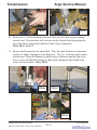
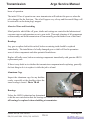
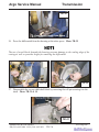
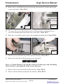
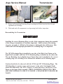
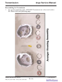
1
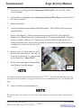
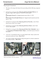
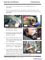
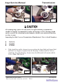
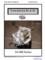
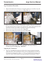
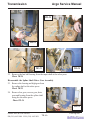
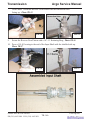
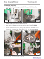
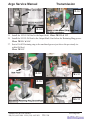
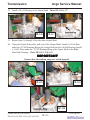
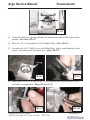
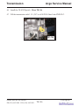
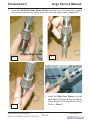
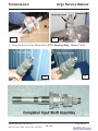
Argo Service Manual Transmission SECTION TR Transmission Table of Contents General Instructions...........................................................................TR-2 Transmission Oil/Maintenance Schedule..........................................TR-3 Recommended Oil....................................................................... ........TR-3 Oil Level Inspection............................................................................ TR-4 Changing the Transmission Oil..........................................................TR-5 Refilling the Transmission with Oil........................................... ........TR-7 General Inspection of the Transmission............................................TR-7 Removing the Transmission....................................................... ........TR-8 Disassembling the Transmission ....................................................... TR-10 Disassembling the Transmission (34-100)Supplement Pages..........TR-2A Separating the Side Cover (Earlier Models).....................................TR-11 Separating the Side Cover (Later Models).......................................TR-12 Disassembling the Shifter Assembly.................................................. TR-18 Disassembling the Differential................................................... ........TR-19 Transmission Component Inspection........................................ ........TR-23 Transmission Component Changes Chart........................................TR-25 Transmission Assembly ......................................................................TR-27 Transmission Assembly (34-100) Supplement Pages....................... TR10A Assembling the Differential................................................................TR-27 Assembling the Differential (34-100) Supplement Pages.................TR-17A Assembling the Shifter Assembly.......................................................TR-33 Assembling the Housing & Cover...................................................... TR-36 Install the Differential.........................................................................TR-42 Install the Shifter Assembly................................................................TR-42 Install the Reverse Idler......................................................................TR-43 Installing the Transmission................................................................ TR-54 Ontario Drive & Gear Limited PH.(519)- 662-2840 FAX (519)- 662-2421 www.odg.com TR-1 Transmission Argo Service Manual General Instructions Detailed information on standard workshop and safety procedures, and general servicing operations is not included in this manual, which has been prepared to assist qualified service personnel. ODG assumes no responsibility or liability for PERSONAL INJURY or VEHICLE DAMAGE which results from any servicing procedure performed, including those instructions outlined in this manual. Before performing a servicing operation, an individual must have determined to his/her satisfaction that a personal injury or vehicle damage will not result from the servicing procedure or tools selected. All transmission work should be performed by a qualified mechanic. Severe damage and/or reduced performance can result from an improperly serviced transmission. Do not attempt to move the gearshift from the neutral starting position until the engine idles down completely. The Argo is equipped with an automatic clutch that is activated by engine speed. If the engine idle speed is too high, the transmission will grind during gear engagement. Ontario Drive & Gear Limited PH.(519)- 662-2840 FAX (519)- 662-2421 TR-2 www.odg.com Argo Service Manual Transmission Transmission Oil Maintenance Schedule The transmission oil should be changed after the initial 25 hours of vehicle operation. After this, it should be changed every 150 operating hours. Proper transmission lubrication will reduce wear, and extend gearbox life. Please use the type, and quantity of transmission oil specified below. Inspecting the condition and level of oil in the transmission must be done on a regular basis. Do not operate the ARGO if the transmission oil level on the dipstick is above or below the grooved indicator. Damage to the transmission or a reduction in vehicle performance could occur. Recommended Oil Type Oil Type: 80W90 Gear Oil HYPOY-C or an EP Rated 80W90 Gear Oil for Extreme Pressure Gear applications. Using any other than the recommended oil could cause serious damage to the transmission components. The approximate refill capacity of the ARGO transmission is 0.85 Liters (1.5 imperial pints, 1.8 U.S pints). However, be sure that it is filled to the full mark on the dipstick. DO NOT OVERFILL. Ontario Drive & Gear Limited PH.(519)- 662-2840 FAX (519)- 662-2421 www.odg.com TR-3 Transmission Argo Service Manual Oil Level Inspection Inspect the transmission oil on a daily basis Do not run the ARGO if the oil level in the transmission shows above or below the mark on the dipstick. Damage to transmission components could occur 1. Place the vehicle on a level surface. This will allow the correct measurement of gear lube in the transmission. 2. Remove the engine access cover and locate the transmission dipstick. Photo to right 3. Clean the transmission around the dipstick location to prevent any dirt from entering the gearbox and causing premature wear to the internal components. 4. TR-01 Remove the dipstick and wipe it clean of oil. Return the dipstick to the transmission and remove it once again. Depending on the age of the vehicle, the dipstick may require a 3/8" opened end wrench to unthread the dipstick from the transmission housing. This could be the case for models built prior to mid 1994. To check the oil level correctly with this style dipstick, unthread it and wipe it clean. Re-thread it back into the housing finger tight, then remove it to view the level. 5. Inspect the oil level. If the level indicated is not even with the mark on the dipstick, go to step 6. Otherwise return the dipstick to the transmission. Ontario Drive & Gear Limited PH.(519)- 662-2840 FAX (519)- 662-2421 TR-4 www.odg.com Argo Service Manual Transmission 6(a) Oil Level Above The Groove i. Insert a vacu-pump hose into the dipstick opening Do not insert the Vacu-pump hose into the transmission if the gearbox oil is extremely hot. Vacu-pump components may melt. ii. Draw out a small quantity of gear oil from the transmission. iii. Remove the vacu-pump from the transmission iv. Repeat steps 1 to 5. 6 (b) Oil Level is Below The Groove i. Place a clean long spouted funnel into the oil fill/dipstick hole ii. Add a small quantity of fresh clean oil as specified in the Recommended Oil Type on page TR-3 of this manual. iii. Remove the funnel and replace the dipstick. Apply a small amount of anti-seize compound to the thread of the dipstick (Older Models) and retighten into the housing with a 3/8" opened end wrench. Changing The Transmission Oil You may drain the transmission’s oil through the oil fill/dipstick, by using a vacuum style pump such as the one available through your ARGO dealer (part # 638-02) or preferably, at the drain plug located at the bottom of the transmission just behind the firewall. Refer to the maintenance schedule in section GI for time change intervals. 1. Drive the vehicle until the transmission is warmed up thoroughly. 2. Park the vehicle on a level surface. Ontario Drive & Gear Limited PH.(519)- 662-2840 FAX (519)- 662-2421 www.odg.com TR-5 Transmission Argo Service Manual 3 Perform the servicing procedure, Removing the Firewall, in Section VB of this service manual. 4 Perform the servicing procedure, Removing the Front Floor Pan, in Section VB of this service manual. 5 Remove the hood. 6 Clean the transmission around the dipstick location. This will keep dirt from entering the gearbox. 7 Remove the dipstick. Vehicles manufactured prior to mid 1994 will require the dipstick to be threaded from the gearbox using a 3/8" opened end wrench. Dipsticks on newer models utilize an "O" ring and need only be pulled straight up and out from the transmission, however the gearshift lever may need to be shifted into low or high gear to allow the dipstick to be removed. 8 Form a piece of sheet metal to place beneath the drain plug to route the oil from the transmission to a plastic bag on the front floor. Photo TR-02 9 Remove the drain plug and clean off any metal filings from the magnet. TR-02 To remove the drain plug easily and effectively, a 7/16" 8 Point Socket must be used. An opened end style wrench or vise grip wrench is not recommended as they will damage the plug. 10 Dispose of the used transmission oil. Be sure to follow any federal or state laws regarding the proper procedure for disposing of oils. Ontario Drive & Gear Limited PH.(519)- 662-2840 FAX (519)- 662-2421 TR-6 www.odg.com Argo Service Manual Transmission Refilling the Transmission with Oil 1 Apply a pipe sealant compound or tape to the drain plug and reinstall. Do not over tighten! 2 Place a clean funnel into the oil fill dipstick hole. 3 Fill the gear box with approximately 0.85 litres (1.5 Imperial Pints, 1.8 U.S. Pints) of clean fresh 80W/90 Gear Lube Hypoy-C or an EP rated 80W/90 gear oil for Extreme Gear Pressure applications. Inspect the level with the dipstick occasionally. 4 Perform the servicing procedure, Transmission Oil Level Inspection. 5 Replace the dipstick. If the dipstick is the thread in type, apply a little anti-seize compound to the threads before installing it back into the transmission. General Inspection Of The Transmission Maintenance Schedule - Inspect every 50 hours. Inspect more often if the vehicle is used under heavy-duty applications. 1. Lift the engine access cover. Problems can occur if ARGO component parts are used for heavy-duty applications. Inspect the transmission for the problems listed below, and perform the recommended servicing procedures. 1. Inspect the transmission casting on both housing and cover for: • cracks or breakage • transmission leakage through the casing If either of these conditions are noted, replace either or both immediately. 2. Inspect the outside of the transmission for: • fluid leakage around seals • fluid leakage around bolt holes • loose bolts If any of these conditions are noted, replace the gasket or seals immediately and tighten all cover bolts to torque specifications. Ontario Drive & Gear Limited PH.(519)- 662-2840 FAX (519)- 662-2421 www.odg.com TR-7 Transmission Argo Service Manual Removing the Transmission 1. Disconnect all wiring to the battery before proceeding with the following component removal. 2. Perform the servicing procedure, Removing the Firewall (Quick Release), for Response, Bigfoot and Conquest in Section VB of this manual. Or: Removing the Firewall for Vanguard models prior to May 19, 1999 Or : Removing the Firewall (Quick Release) for Vanguard models manufactured after May 19, 1999. 3. Perform the servicing procedure, Removing the Front Floor Pan, in the Vehicle Body Section of this service manual. 4. Perform the servicing procedure, Removing the Driven Clutch, in the Clutch Section of this manual. 5. Perform the servicing procedure, Removing the Brake Pads ( Hydraulic ) steps 15, or Removing the Mechanical Brake Calipers, in the Brake System Section of this manual. 6. Locate the (3) mounting bolts that secure the hydraulic brake caliper system to the transmission and remove them. Photo TR-03 7. On Conquest models, disconnect the wiring at the igniter box which is mounted to the steering assembly. Photo TR-04 TR-03 Ontario Drive & Gear Limited PH.(519)- 662-2840 FAX (519)- 662-2421 TR-04 TR-8 www.odg.com Argo Service Manual Transmission 8. Unfasten the twist grip assembly from the steering handle and remove it. Photo TR-05 9. Remove the entire hydraulic brake system from the vehicle. The calipers, master cylinders and brake lines can all remain attached without the loss of any brake fluid. Photo TR-06 TR-06 TR-05 10. Perform the servicing procedure Removing the Drive Chains, in Section WA of this service manual. 11. Perform the servicing procedure, Removing the Brake Disc, in Section BR of this service manual. 12. Locate, unfasten and remove the (2) bolts, lock washers and nuts that secure the transmission to the power pack frame. Photo TR-07 TR-07 13. Remove the transmission guard from the transmission. It is secured with (2) bolts and (2) flatwashers. Photo TR-08 14. Loosen off the carriage bolt of the dash support and turn it 90 degrees. Tilt the transmission back towards the drivers compartment and lift it from the vehicle. TR-08 15. Place the transmission on a clean workbench for disassembly. Ontario Drive & Gear Limited PH.(519)- 662-2840 FAX (519)- 662-2421 www.odg.com TR-9 Transmission Argo Service Manual Disassembling the Transmission 1. Remove the Drain Plug & drain the oil from the transmission. Photo TR-09 2. Remove the Dipstick. 3. Remove the Retaining Ring that secures the Reverse Idler Dowel Pin on the outside of the Cover. Photo TR-10 4. Tap the Dowel pin back into the transmission far enough to free it from the Side Cover. You will need a drift punch to tap it below the surface of the cover. TR-11 5. Remove all side cover fasteners. Photo TR-12 TR-09 TR-10 TR-11 TR-12 6. Position the transmission to remove the Retaining Ring on the Output Shaft of the Housing side. Photo TR-13 7. Remove the Shim from the Output Shaft. Photo TR-14 Ontario Drive & Gear Limited PH.(519)- 662-2840 FAX (519)- 662-2421 TR-10 www.odg.com Argo Service Manual Transmission TR-13 TR-14 All retaining rings, spacers & seals need to be replaced during a transmission rebuild. It is usually recommended to replace all bearings as well. Bearings should only be reused if the technician has determined to his/her own satisfaction that they are okay to reuse. Separating the Side Cover on Transmissions Manufactured Prior to Serial Numbers: 8. 25631GU, 25668HU 25700MU With a dead blow mallet, alternate between striking the Input Shaft and Output Shaft until the Cover begins to separate from the Housing. Continue until the Cover is completely free of the Housing. In most cases the differential will remain with the Cover. Photo TR-15 & 16 TR-15 Ontario Drive & Gear Limited PH.(519)- 662-2840 FAX (519)- 662-2421 TR-16 www.odg.com TR-11 Transmission Argo Service Manual Separating the Side Cover on Transmissions Manufactured From Serial Numbers: 9. 25631GU, 25668HU 25700MU These Side Covers utilize a threaded boss in 2 locations. Photo TR-17 10. Remove the Retaining Ring and Shim on the Output Shaft side of the Cover, Photo TR-18, and ensure that the reverse idler dowel pin has been freed of the cover as in step 3 & 4 11. Thread (2) 5/16"x18 bolts into the threaded boss at both locations on the Side Cover. As the bolts come in to contact with the Housing below, the Cover is pulled from the Output Shaft. Thread the bolts a little at time alternating between the two. This will ensure that it does not bind during separation. Photo TR-19 TR-17 TR-18 TR-19 TR-20 Make sure that the bolts threaded into the Cover are long enough to guarantee that the Cover will completely separate itself from the Housing and may be easily lifted off by hand. In most cases, with this type of separation, the differential will remain within the Housing. Photo TR-20 Remove the differential from the Housing as described in step 8. Ontario Drive & Gear Limited PH.(519)- 662-2840 FAX (519)- 662-2421 TR-12 www.odg.com Argo Service Manual Transmission 12. Remove the Shifter Assembly. Locate the Plug Plate on the Housing side and with a hammer and punch, knock the Plug Plate through at the center until the Shifter Assembly is freed from the Bearing. Photo TR-21 13. If the 101-01 Bearing has remained on the Input Shaft it will be necessary to remove it using a gear puller. Photo TR-22 & 23 14. Slip the Reverse Idler gear from the ½” Dowel Pin. Photo TR-24 15. TR-21 TR-22 TR-23 TR-24 Remove the Input Shaft’s Oil Seal. Photo TR-25 16. Remove the Input Shaft’s Retaining Ring. Photo TR-26 17. Remove the Shim installed below the Retaining Ring. Photo TR-27 Ontario Drive & Gear Limited PH.(519)- 662-2840 FAX (519)- 662-2421 TR-25 www.odg.com TR-13 Transmission Argo Service Manual TR-27 TR-26 Some transmissions may have (2) Shims instead of (1). In rare cases there may be none used. In any case, when reassembling, use the same amount as were used originally. 18. Using a soft faced hammer, tap the Input Shaft out of the Housing. Photo TR-28 19. Place the Housing in the assembly fixture to remove all Bearings, Retaining Rings, Seals and the Plug Plate. 20. Remove the old Cover Gasket. Photo TR-29 TR-28 TR-29 21. Knock the outer Bearing from the Housing using a hammer and drift punch. Tap around the perimeter of the Bearing through the backside of the housing to ensure that it will not bind . Photo TR-30 22 Knock out the Housing Plug Plate. Photo TR-31 Ontario Drive & Gear Limited PH.(519)- 662-2840 FAX (519)- 662-2421 TR-14 www.odg.com Argo Service Manual Transmission TR-30 TR-31 23. Flip the Housing over to remove the outer Retaining Ring. Photo TR-32 24. Using the drift punch and hammer remove the inner Bearing in the same manner as in step 20. Photo TR-33 IMPOR TANT IMPORT When removing this Bearing, take note of the number of Shims that were installed behind it. This may vary from 1 to 2 shims. In any case, be sure to install the same amount as was used previously. Photo TR-34 25. Flip the transmission and remove the inner Retaining Ring. Photo TR-35 TR-32 TR-33 TR-34 TR-35 Ontario Drive & Gear Limited PH.(519)- 662-2840 FAX (519)- 662-2421 www.odg.com TR-15 Transmission Argo Service Manual 26. Remove the inner Seal with a hammer and drift punch. Photo TR-36 27. If the transmission you are disassembling still has the differential assembly in the Side Cover as described in step 8, it will have to be removed from the Cover using an arbor press. First you must remove the Retaining Ring and Shim washer from the Output Shaft. Photo TR-37 & 38 28. Supporting the Cover on each side with 2 short 2x4’s, place it in an arbor press and apply pressure to the Output Shaft. Press the differential from the Cover. Photo TR-39 29. Place the Cover into the assembly fixture and remove all Bearings, Seals & Retaining Rings in a similar manner as performed on the housing. There are 2 plug plates in the Cover side compared to the single one used in the Housing. There are no Shims used behind the inner Bearing of the Cover TR-36 TR-37 TR-38 TR-39 Ontario Drive & Gear Limited PH.(519)- 662-2840 FAX (519)- 662-2421 TR-16 www.odg.com Argo Service Manual Transmission IMPOR TANT IMPORT Transmissions manufactured from Oct of 2000 have had a design change to the Side Cover. This new Side Cover begins on vehicles manufactured from serial numbers: SN11905 TB Oct. 4/00 S11906 TB Oct. 4/00 BF11917 OB Oct. 10/00 CB17471 YB Oct. 12/00 RB17525 TB Oct. 24/00 This Side Cover no longer requires the 31-07 plug or the 106-01 Retaining Ring. The Side Cover has been cast and machined in this area to eliminate the need for both of these parts. The cover will replace all earlier side covers. Photo TR-40 The procedure for removing the 101-01 Bearings will require the use of an internal style of puller as described below. TR-40 TR-41 30. Place the Side Cover into the assembly fixture with the Bearings facing up. Photo TR-41 31. Adjust the internal bearing puller to the closed position. Photo TR-42 32. Insert the bearing puller into the inner race of the 101-01 bearing and tighten the adjustment nut until the puller has spread enough to secure the bearing from the inside. Photo TR-43 Ontario Drive & Gear Limited PH.(519)- 662-2840 FAX (519)- 662-2421 TR-42 www.odg.com TR-17 Transmission Argo Service Manual TR-43 TR-44 33. Take a piece of flat stock with a hole drilled to the center and slip it on to the threaded adjustment rod of the puller. Secure it with a nut. Photo TR-44 34. Flip the Cover on the assembly jig so that the 101-01 Bearings are facing down. Photo TR-45 35. Use a mallet to strike the flat stock and knock the 101-01 Bearing from the casting. Photo TR-46 TR-46 TR-45 Disassembling the Shifter Assembly 36. The Shifter Assembly consists of the Splined Shaft, Drive Gear and Double Gear. Photo TR-47 The Double Gear slides along the Splined Shaft and locks into 4 different shift gate positions (Reverse, Neutral, Low & High Gear). Each position is locked by a Ball & Spring within the Double Gear, and gates machined within the Splined Shaft. Ontario Drive & Gear Limited PH.(519)- 662-2840 FAX (519)- 662-2421 TR-18 TR-47 www.odg.com Argo Service Manual Transmission 37. Place the Shifter Assembly into the arbor and press the Splined Shaft from the 101-01 Bearing and the Double Gear. Photo TR-48 Be aware of the Ball & Spring within the Double Gear when pressing the spline shaft from the assembly. 38. Turn the Splined Shaft to the other end to remove the 101-01 Bearing and Drive Gear. Photo TR-49 TR-48 TR-49 Disassembling the Differential 40. Secure the Differential by the Output shaft on the cage side within a vise. A vise equipped with aluminum jaws must be used to avoid any damage to the output shaft. Photo TR-51 TR-51 When removing the 3 fasteners that secure the differential's Gear Plate and Aluminum cage together, earlier transmissions may also have a lockwasher installed. If this is the case, when reassembling the differential, eliminate the lockwashers and use Red 271 LOCTITE on both the threads of the fastener as well as on the internal threads of the aluminum cage. Ontario Drive & Gear Limited PH.(519)- 662-2840 FAX (519)- 662-2421 www.odg.com TR-19 Transmission Argo Service Manual 41. Hold the Output Shaft from turning while removing the 3 Fasteners that hold the Gear Plate and Aluminum Cage together. Photo TR-52 42. With the Fasteners removed, gently tap the Gear Plate from the Aluminum Cage using a soft faced mallet. Photo TR-53 TR-52 TR-53 When lifting the Gear Plate from the Cage, be aware of any Pinions that may come with the Gear Plate. Avoid any of these falling to the floor. Any damage to these pinions can result in reduction of gear life or noise issues. 43. Remove each of the (6) Pinions. Photo TR-54 44. Remove the Retaining Ring that secures the Sun Gear to the Output Shaft on the Aluminum Cage side. Photo TR-55 TR-55 TR-54 45. Slip the Sun Gear from the Output Shaft. Photo TR-56 46. Remove the Retaining Ring that secures the second Sun Gear to the Output Shaft on the Gear Plate side. Photo TR-57 Ontario Drive & Gear Limited PH.(519)- 662-2840 FAX (519)- 662-2421 TR-20 www.odg.com Argo Service Manual Transmission TR-56 TR-57 47. Slip the Sun Gear from the Output Shaft. Photo TR-58 48. Press the Output Shafts from both Cage and Gear Plate. Photo TR-59 & 60 TR-59 TR-58 TR-60 49. Remove each of the 101-15 Bearings from both Cage and Gear Plate. Slip the bearing remover tool into each of the aforementioned components and tap with your hand or soft faced mallet. Photo TR-61 & 62 TR-61 Ontario Drive & Gear Limited PH.(519)- 662-2840 FAX (519)- 662-2421 www.odg.com TR-21 Transmission Argo Service Manual TR-62 TR-63 50. Remove all (12) Oilite Bushings from both Cage and Gear Plate using a bushing removal tool. This procedure will also push out the Output Shaft Bearing that has more than likely remained assembled to both of these components. Photo TR-63, 64 & 65 51. Remove the Bearing from the Input Shaft. Place the Input Shaft into an aluminum jawed vise, lightly clamping it to the High Gear. The vise, need only make contact with the gear. Being the Bearing is slightly larger in diameter than the High Gear, the vise jaws will hold the bearing up while gently tapping the Input Shaft down with a soft faced mallet. Photo TR-66 TR-64 TR-65 TR-66 Ontario Drive & Gear Limited PH.(519)- 662-2840 FAX (519)- 662-2421 TR-22 www.odg.com Argo Service Manual Transmission 52. Wash all parts in a clean varsol bath and dry all parts with compressed air or a lint free rag. Lay out all parts for inspection. Photo TR-67 TR-67 Always exercise extreme caution when using compressed air. Compressed air can be potentially dangerous causing serious injury or even death if misused. Transmission Component Inspection Mechanical transmissions do not need a great deal of maintenance beyond periodic and regular oil changes. However, once a problem has been detected and the transmission has been disassembled, it is important to examine all transmission components for wear, cracks or breakage. Repairing or replacing all faulty components will prevent further premature breakdowns and the need to disassemble the transmission again in the near future. Inspect all transmission components and look for Broken or badly worn teeth Worn out or seized up bearings Badly worn spline shafts Cracks in the transmission housing or cover Gear Wear Lack of lubrication, wrong type of lubrication or transmission overheating may cause excessive wear or damage to transmission gears. When inspecting gears, follow these guidelines. Normal Wear As gears operate, the meshing operation and oil wash will polish the gear teeth, removing any sharp edges, imperfections or shards. The polished surface should cover the entire length and depth of the teeth. Well lubricated gears will show this condition after many Ontario Drive & Gear Limited PH.(519)- 662-2840 FAX (519)- 662-2421 www.odg.com TR-23 Transmission Argo Service Manual hours of operation. The initial 25 hrs of operation on a new transmission will indicate this process when the oil is changed for the first time. The oil will appear very silvery and fine metal filings will be noticeable on the drain plug's magnet. Abrasive Wear and Scratching Metal particles which flake off gears, shafts and castings are carried in the lubricant and can cause uneven and premature wear to gear teeth. Thorough cleaning of all components at disassembly and fresh transmission oil can normally prevent further wear of this kind. Breakage Any gear or spline shaft with cracked, broken or missing teeth should be replaced immediately. The installation of a badly damaged gear or shaft will lead to premature wear of other components and other potential breakdowns. Replace all badly worn, broken or missing components immediately with genuine ARGO replacement parts. If there is any doubt as to whether the transmission component needs replacing, generally the best thing to do is to replace it while the job is at hand. Aluminum Cage Inspect the aluminum cage for any hairline cracks, especially at the shoulder where the inner bearing is seated. Photo TR-68 Bearings TR-68 Unless the ARGO technician has determined to his/her own satisfaction that the bearings are suitable to reuse, it is recommended that all bearings be replaced when rebuilding a transmission. Ontario Drive & Gear Limited PH.(519)- 662-2840 FAX (519)- 662-2421 TR-24 www.odg.com Argo Service Manual Transmission Argo Transmission Assembly Transmission Component Changes Since 1992 This chart indicates changes to some of the transmission components since 1992. Most, if not all are fully exchangeable if your original part is no longer available. When ordering replacement parts, begin by referring to the correct parts manual for your year and model of ARGO. If the component is no longer listed in your Spare Parts Price List (Distributors & Dealers Only), check the Superceded Section for the correct part(s) that replace(s) the original. Transmission Component Shaft, Splined & Gear, Helical Affects earlier Vanguards 34-81 Output Shaft 610-24H Brake Disc 810-01 Brake Disc From Serial Numbers: CB16459 TB Oct. 27/99 RB16446TB Oct. 26/99 BF11143 TB Oct. 21/99 S11188 TB Nov. 17/99 SN11196 TB Nov. 17/99 Shift Gate (New) From Serial Numbers: Description of Change Apr 29/1992 Keys are eliminated on the spline shaft. Helical gears and splined shafts are coupled by an extended 6PL.-spline. Fully Exchangeable. Jul 07/1999 The output shaft and brake discs are now splined eliminating the need for the 110-14 keys. Older stock is still available. Fully Exchangeable but both shaft and disc need to be replaced together. Refer to the appropriate illustrated parts manual for the new part numbers. Jun 12/2000 Reason for Change -To limit the possibility of the transmission coming out of gear in certain situations. SN11905 TB Oct. 4/00 S11906 TB Oct. 4/00 BF11917 TB Oct. 10/00 CB17471 YB Oct. 12/00 RB17525 Oct. 24/00 Ontario Drive & Gear Limited PH.(519)- 662-2840 FAX (519)- 662-2421 www.odg.com TR-25 Transmission Argo Service Manual Transmission Component Transmission Cover From Serial Numbers: SN11905 TB Oct. 4/00 S11906 TB Oct. 4/00 BF11917 OB Oct. 10/00 CB17471 YB Oct. 12/00 RB17525 TB Oct. 24/00 Reverse Idler (34-16A) From vehicles manufactured from July 3, 2001 Shim Washer between Housing and Shifter Assy. Description of Change Aug 11/2000 The side cover is cast solid in the area of the input shaft and shifter assembly at the 101-01 bearings. This eliminates the need for the 31-07 plug plates & 106-01 retaining rings normally used here. Fully Exchangeable. July 3, 2001 Reverse Idler has two 105-03 bushings instead of a single, 105-05 bushing, along with two radial holes drilled in for better lubrication. Fully Exchangeable Apr 16/2002 To address the issue of the retaining ring in some cases, popping off of the shift yoke due to interference on the casting. Any transmission being serviced and rebuilt between Serial Numbers: CB17404 - CB19432, RB17525 RB19502, BF11917 - BF13347, SN11905 - SN13349, or S11906 - S13350, would benefit from having this new 108-74 shim washer installed at the time of a rebuild. Even though this may not have been an issue, it will be a good precautionary measure for the future. Ontario Drive & Gear Limited PH.(519)- 662-2840 FAX (519)- 662-2421 TR-26 www.odg.com Argo Service Manual Transmission Transmission Assembly Assembling the Differential 1. Secure the Aluminum Cage to the base of the arbor press using a spacer and nut. Photo TR-69 2. Install (6) Oilite Bushings into the Aluminum Cage. Photo TR70 3. Repeat the process installing these bushings into the appropriate Gear Plate. Photo TR-71 The (3) Gear Plates used are: M-Gear Plate H-Gear Plate G-Gear Plate 4. Blow all foreign debris from the Cage and Gear Plate. Photo TR-72 TR-69 TR-70 TR-71 Ontario Drive & Gear Limited PH.(519)- 662-2840 FAX (519)- 662-2421 TR-72 www.odg.com TR-27 Transmission Argo Service Manual 5. Install a Bearing into both Cage and Gear plate. Photo TR-73 & 74 6. Wipe the Output Shaft free of debris with a lint free rag. Install this Output Shaft into the Aluminum Cage. Photo TR-75 & 76 See Transmission Component Changes chart on page TR-25 regarding output shafts. TR-73 TR-74 TR-75 TR-76 Use a spacing tool to secure the previously installed Bearing inside the Aluminum Cage while the Output Shaft is pressed into place. Photo TR-77 TR-77 Ontario Drive & Gear Limited PH.(519)- 662-2840 FAX (519)- 662-2421 TR-28 www.odg.com Argo Service Manual Transmission 7. Orient the Sun Gear as in Photo TR-78 with the higher shoulder side facing up. Install it to the splined end of the Output Shaft. Photo TR-79 & 80 8. Secure the Sun Gear with a Snap Ring. Photo TR-81 9. Be sure the Retaining Ring is properly seated to the machined groove of the Output Shaft. Photo TR-82 Press the Output Shaft from the inside of the cage to seat the Retaining Ring snuggly against the Sun Gear. Photo TR-83 TR-78 TR-79 TR-80 TR-81 TR-82 TR-83 Ontario Drive & Gear Limited PH.(519)- 662-2840 FAX (519)- 662-2421 www.odg.com TR-29 Transmission Argo Service Manual 10. Wipe down the 2nd Output Shaft and assemble to the Gear Plate using the same method as described for the Aluminum Cage. Photo TR-84, 85 & 86 TR-84 TR-85 TR-86 TR-87 11. Orient the 2nd Sun Gear as in instruction 8 and install and secure it with a 107-04 Retaining Ring using the same method as described for the Aluminum Cage in instruction 10. Photo TR-87, 88, 89 & 90 TR-89 TR-88 Ontario Drive & Gear Limited PH.(519)- 662-2840 FAX (519)- 662-2421 TR-30 www.odg.com Argo Service Manual Transmission TR-90 TR-91 12. Set the assembled Aluminum Cage into an assembly stand or an aluminum jawed vise Photo TR-91 13. Install (6) Pinions into the Oilite Bushings of the Aluminum Cage alternating the Pinions in an up and down manner as shown in Photo TR-92 & 93 14. LOCTITE the (3) threaded holes of the Aluminum Cage with Red 271 LOCTITE. Photo TR-94 15. Assemble the Gear Plate to the Aluminum Cage. Align the top of the Pinions in the Cage, with the Oilite Bushings in the Gear Plate. Photo TR-95 & 96 TR-92 TR-93 TR-94 TR-95 Ontario Drive & Gear Limited PH.(519)- 662-2840 FAX (519)- 662-2421 www.odg.com TR-31 Transmission Argo Service Manual 16. Seat the Gear Plate to the Aluminum Cage using a soft faced mallet. Photo TR-97 17 Apply Red 271 LOCTITE to each of the (3) fasteners, Photo TR- 98, and tighten down. Torque to specifications. Photo TR-99 & 100 TR-96 TR-97 TR-98 TR-99 TR-100 Ontario Drive & Gear Limited PH.(519)- 662-2840 FAX (519)- 662-2421 TR-32 www.odg.com Argo Service Manual Transmission 18. Locate the Spline Shaft and assemble the appropriate Drive Gear to the splined end of it. Orient the gear with the machined side down. Photo TR-101, 102 & 103 Drive Gears are as follows: M Drive Gear H Drive Gear G Drive Gear 19. Place a Double Gear into the assembly stand or an aluminum jawed vise on the work bench. Place it into the stand with the machined hole side up. Photo TR-104 & 105 20. Install a Spring to the inner hole of the Double Gear. Photo TR-106 & 107 TR-101 TR-102 TR-103 TR-104 Ontario Drive & Gear Limited PH.(519)- 662-2840 FAX (519)- 662-2421 www.odg.com TR-33 Transmission Argo Service Manual TR-105 TR-107 TR-106 TR-108 21. Place a Ball Bearing to the top of the spring. Photo TR-108 & 109 TR-109 22. Compress the Ball Bearing into the hole of the Double Gear with a flat screwdriver, at the same time inserting the Spline Shaft from the opposite side with the shift gate notches facing down. These notches will mate with the Ball Bearing within the Double Gear when the shifter assembly is completed. Photo TR-110, 111 & 112 (following page.) Ontario Drive & Gear Limited PH.(519)- 662-2840 FAX (519)- 662-2421 TR-34 www.odg.com Argo Service Manual Transmission TR-110 TR-111 TR-112 TR-113 23. Use a soft face mallet to tap the Spline Shaft completely through the Double Gear. Photo TR-113 & 114 24. Remove the assembly to the bench. Grabbing the Double Gear in your hands, shift the Double Gear up and down the length of the Spline to check that all shift gates are smooth and lock securely. Photo TR-115 TR-114 Ontario Drive & Gear Limited PH.(519)- 662-2840 FAX (519)- 662-2421 TR-115 www.odg.com TR-35 Transmission Argo Service Manual Assembling the Housing and Cover 25. Install a Retaining Ring into the inner groove on the Output Shaft side of the Transmission Cover. Photo TR-116 & 117 26. Install the Bearing into the Side Cover with the arbor press. Seat it to the previously installed Retaining Ring. Photo TR-118 & 119 TR-116 TR-118 TR-117 TR-119 27. Apply yellow LOCTITE 641 to the outer edge of (2) Bearings and press them into the Side Cover. Be sure the shielded side is facing down. Photo TR120, 121 & 122 IMPOR TANT IMPORT Vehicles Manufactured prior to S/N CB17471, RB17525, BF11917, SN11905 & S11906 require 2 retainings rings to be installed to the cover first before the bearings are pressed into place. Ontario Drive & Gear Limited PH.(519)- 662-2840 FAX (519)- 662-2421 TR-36 TR-120 www.odg.com Argo Service Manual Transmission TR-121 TR-122 28. Install a Retaining Ring to the inner groove of the Housing’s Output Shaft side. Photo TR-123 & 124 29. Install a Retaining Ring into the Housing at the shifter assemblies bearing side. Photo TR-125 & 126 TR-123 TR-124 TR-125 TR-126 30. Apply 592 LOCTITE Teflon pipe sealant to the Magnetic Oil Drain Plug and install it into the housing. Tighten only snug into Housing. Photo TR-127 & 128 Ontario Drive & Gear Limited PH.(519)- 662-2840 FAX (519)- 662-2421 www.odg.com TR-37 Transmission Argo Service Manual TR-127 TR-128 31. Tap a burnishing tool through the shifter assembly's Oilite Bushing if the old bushing has been replaced with a new one Photo TR-129 32. Place a Shim Washer on top of the previously installed Retaining Ring in the Housing’s Output Shaft side. Photo TR-130 & 131 (This may vary between 1 or 2 shims. Use the quantity previously used.) 33. Install the Bearing to the top of the shim and seat with the arbor press. Photo TR132 & 133 34. Install (1) Bearing, shielded side down, into the Housing’s Shifter Assembly side. Photo TR-134 & 135 (following Page) TR-129 TR-131 Ontario Drive & Gear Limited PH.(519)- 662-2840 FAX (519)- 662-2421 TR-38 TR-130 TR-132 www.odg.com Argo Service Manual Transmission TR-133 TR-134 TR-135 TR-136 35. Install the 34-63 Shifter Yoke to the 34-65 Shifter Assembly securing it with a 10705 Retaining Ring. Photo TR-136, 137 & 138 TR-137 TR-138 36. Install the 113-01 “O” ring to the 34-65 Shifter Assembly. Photo TR-139 & 140 (following page) 37. From the inside of the Housing, slip the Shifter Assembly through the Oilite Bushing at the top of the Housing. Photo TR-141 (following page). Any transmission being serviced and rebuilt between Serial Numbers: CB17471 - CB19432, RB17525 - RB19441, BF11917 - BF13347, SN11905 - SN13349, or S11906 - S13350, would benefit from having this new 108-74 shim washer installed at the time of the rebuild. Even though this may not have been an issue, it will be a good precautionary measure for the future. Photo TR-142 Ontario Drive & Gear Limited PH.(519)- 662-2840 FAX (519)- 662-2421 www.odg.com TR-39 Transmission Argo Service Manual TR-139 TR-140 TR-142 TR-141 38. Orient and secure the Shift Lever Holder to the Shift Shaft using (2) Roll Pins as shown in Photo TR-143. Be sure to support the shaft from below with a piece of metal stock when hammering the pins through the Holder. Photo TR-144 TR-143 Ontario Drive & Gear Limited PH.(519)- 662-2840 FAX (519)- 662-2421 TR-40 TR-144 www.odg.com Argo Service Manual Transmission 39. Insert the Dowel Pin into the boss of the transmission housing and using a soft face mallet, tap it flush to the sealing edge of the housing. Photo TR-145 TR-145 40. Install the Retaining Ring to the bottom of the Dowel Pin. Photo TR-146 TR-146 41. Attach the Shifter Lever assembly temporarily to the Holder. Photo TR-147 42. Place the Housing into a fixture for final assembly. Photo TR-148 TR-147 Ontario Drive & Gear Limited PH.(519)- 662-2840 FAX (519)- 662-2421 TR-148 www.odg.com TR-41 Transmission Argo Service Manual 43. Use compressed air to blow any foreign debris from the Housing before attempting to install the sub-assembled components. Photo TR-149 TR-149 Install the Differential Assembly. 44. Place the Differential into the Housing, slipping the Output Shaft into the Output Shaft Bearing. Press at the arbor until the shoulder of the Aluminum Cage is seated to the Bearing. Photo TR-150, 151 & 152 Install the Shifter Assembly 45. Take the pre-assembled Shifter Assembly and place the Double Gear into the high gear gate on the spline (Lowest Position). Photo TR-153 TR-150 Ontario Drive & Gear Limited PH.(519)- 662-2840 FAX (519)- 662-2421 TR-42 TR-151 www.odg.com Argo Service Manual Transmission TR-152 46. Install the Shifter Assembly into the Housing, lining up the one end of the Spline Shaft with the bearing in the Housing. At the same time, be sure to slip the Shift Yoke over the larger diameter gear of the Double Gear. Photo TR-154 TR-153 TR-154 47. Tap the assembly with a soft faced hammer until the shoulder of the Spline Shaft seats to the Bearing. Photo TR155 & 156 TR-155 TR-156 Install the Reverse Idler 48. Press (2) Oilite Bushings into the Reverse Idler. Press one in from each end. Photo TR-157 & 158 Models manufactured prior to July 3, 2001 have a single oilite bushing and no radial holes drilled in the reverse gear Ontario Drive & Gear Limited PH.(519)- 662-2840 FAX (519)- 662-2421 TR-157 www.odg.com TR-43 Transmission Argo Service Manual TR-159 TR-158 49. If the old bushing(s) was/were replaced with new, press a burnishing tool through the Oilite Bushing of the Reverse Idler. Photo TR-159 & 160 50. Slip the Reverse Idler on to the Dowel Pin making sure that the chamfer side is facing down. Photo TR-161, 162 & 163 TR-160 TR-161 TR-162 TR-163 Ontario Drive & Gear Limited PH.(519)- 662-2840 FAX (519)- 662-2421 TR-44 www.odg.com Argo Service Manual Transmission 51. While one hand holds the top of the Shifter Assembly, Use the other to shift the Lever through all gates. Check that all shift smoothly. Photo TR-164 52. Spin the entire assembly at the Output Shaft to check for any tight spots or unusual noises. Photo TR-165 TR-164 TR-165 53. Apply Black 598 LOCTITE RTV Silicon Gasket Maker to the bottom half of the Housing. Photo TR-166 54. Install the Cover Gasket to the sealing edge of the Housing. Photo TR-167 TR-166 TR-167 55. Apply the same gasket compound to the lower edge of the Side Cover as well. Photo TR-168 (following page) 56. Install the Cover to the Housing and press to fit. Photo TR-169,170 & 171 When applying pressure to the cover at the press, use a soft faced mallet to tap the top end of the cover at the same time to ensure that the cover is not installed crooked. Photo TR-172 & 173 (following page) Ontario Drive & Gear Limited PH.(519)- 662-2840 FAX (519)- 662-2421 www.odg.com TR-45 Transmission Argo Service Manual TR-168 TR-169 TR-170 TR-171 TR-172 TR-173 Ontario Drive & Gear Limited PH.(519)- 662-2840 FAX (519)- 662-2421 TR-46 www.odg.com Argo Service Manual Transmission 57. Secure the Cover using (1) Cap Screw, (4) Bolts and (4) Lock Washers. Apply LOCTITE Silver Grade anti-seize to the cap screw before installing to the lower end of the transmission assembly. Photo TR-174 & 175 TR-174 TR-175 58. Secure the Cover and torque to specifications. Photo TR-176 & 177 Tighten down all fasteners in a cross corner sequence. TR-176 Apply a little gear oil to the inner lip of the Oil Seal to ease assembly around the Output Shaft and prevent any deformity during installation. Photo TR-178 Ontario Drive & Gear Limited PH.(519)- 662-2840 FAX (519)- 662-2421 TR-177 TR-178 www.odg.com TR-47 Transmission Argo Service Manual 59. Press the inner Oil Seal to the Output Shaft. Seat it to the Retaining Ring that was previously installed in the Housing in step 29. Do not over press. Photo TR-179, 180 & 181 60. Install a Retaining Ring to the top of the Oil Seal. Photo TR-182 & 183 TR-179 TR-180 TR-181 TR-182 TR-183 Ontario Drive & Gear Limited PH.(519)- 662-2840 FAX (519)- 662-2421 TR-48 www.odg.com Argo Service Manual Transmission 61. Press the outer Sealed Bearing into the Side Cover and seat it to the Retaining Ring. Photo TR-184, 185 & 186 62. Rotate the transmission assembly and repeat steps 59-61 to the Housing side. TR-184 TR-185 TR-186 TR-187 63. Place the transmission back into the rotating fixture and thread the output shaft puller on to the Output Shaft. Photo TR-187 64. While holding the Output Shaft with the specialized tool holder, thread the hex head bolt into the Output Shaft and tighten it down until the shaft has been pulled towards the outside of the Housing. Pull the shaft far enough to install the Shim Washer and Retaining Ring to the machined groove of the Output Shaft. Photo TR-188, 189, 190 & 191 (following Pages) IMPOR TANT IMPORT Output Shaft Shims come in two thicknesses. Generally, the .040" Shim Washer is installed on the cover side, and the .020" Shim Washer, is installed on the Housing Side. However, there may be cases when only the thinner of the two washers fit on the Cover Side and rare cases when the Output Shafts receive no Shim Washers at all Ontario Drive & Gear Limited PH.(519)- 662-2840 FAX (519)- 662-2421 www.odg.com TR-49 Transmission Argo Service Manual TR-188 TR-189 TR-190 TR-191 65. Rotate the transmission to access the Input Shaft side of the transmission. Photo TR-192 66. Seat the Reverse Idler Pin's Retaining Ring to the pin boss located in the transmission Housing. Through the Input Shaft opening, use a hammer and pin installer to tap the Reverse Idler Pin through the boss and out the Transmission Cover side. Seat the Retaining Ring to the boss. Photo TR-193 & 194 Do not over drive the Idler Pin Retaining Ring against the boss. Damage and deformation to the retaining ring could result in the possibility of it coming off during application. TR-192 Ontario Drive & Gear Limited PH.(519)- 662-2840 FAX (519)- 662-2421 TR-193 TR-50 www.odg.com Argo Service Manual Transmission TR-194 TR-195 67. Rotate the Transmission and secure the opposite end of the Reverse Idler Pin with a 2nd Retaining Ring. Photo TR-195 68. Once the Retaining Ring has been secured to the Cover Side, use a hammer and tap the pin back in the opposite direction to seat the Retaining Ring to the Cover. Photo TR-196 TR-196 TR-197 69. Wipe off the Input Shaft with a lint free rag to remove any oil and debris and insert it into the Input Shaft opening. Use a soft faced mallet to seat the Input Shaft to the Bearing on the Cover Side. Photo TR-197, 198 & 199 TR-198 Ontario Drive & Gear Limited PH.(519)- 662-2840 FAX (519)- 662-2421 TR-199 www.odg.com TR-51 Transmission Argo Service Manual 70. Rotate the Input Shaft to check that it turns freely. Photo TR-200 71. Place the Input Bearing over the Input Shaft and seat it with a soft faced mallet and installation tool. Photo TR-201, 202 & 203 TR-200 TR-201 TR-202 TR-203 72. Place (1) Shim Washer on top of the previously installed Bearing. Photo TR-204 A transmission may utilize either 1 or 2 shims here. When reassembling, always install the original quantity. 73. Install and seat the Retaining Ring. Photo TR-205 & 206 TR-205 TR-204 Ontario Drive & Gear Limited PH.(519)- 662-2840 FAX (519)- 662-2421 TR-52 www.odg.com Argo Service Manual Transmission TR-206 TR-207 TR-208 TR-209 74. Install the Oil Seal to the Input Shaft using a soft faced mallet and seal installation tool. Photo TR-207, 208 & 209 75. Apply 680 Green LOCTITE to the plug plate sealing edge and tap it into the Housing using a steel hammer. Photo TR-210, 211 & 212 TR-210 See Transmission Component Changes chart on page TR-26 regarding plug plates and side covers. TR-211 Ontario Drive & Gear Limited PH.(519)- 662-2840 FAX (519)- 662-2421 www.odg.com TR-53 Transmission Argo Service Manual TR-212 TR-213 76. Place the transmission on the bench and perform a final shift through all gears. 77. Fill with .805 Litres of 80/90 Gear Oil. Photo TR-213 78. Install the Dipstick and check oil level. Installing the Transmission 1. Locate the dash support and move it 90 degrees so that it will not interfere when installing the transmission back into the vehicle. Photo TR-214 2. Place the transmisson back into the power pack frame of the vehicle and install both mounting bolts. Apply blue 242 LOCTITE to the threads of the bolts and secure with a lockwasher and nut. Torque to specifications. Photo TR-215 TR-215 TR-214 3. Next install the driven clutch guard. Apply blue 242 LOCTITE to the 2 mounting bolts and secure tightly. Torque to specifications. Photo TR-216 4. Reposition the dash support back down to the top of the transmission and tighten. Photo TR-217 Ontario Drive & Gear Limited PH.(519)- 662-2840 FAX (519)- 662-2421 TR-54 www.odg.com Argo Service Manual Transmission TR-217 TR-216 5. If the vehicle utilizes the hydraulic brake system, reattach the entire assembly to the transmission using the 3 mounting bolts and lockwashers. Torque to specifications. Photo TR-218 TR-218 All brake lines and calipers should still be attached to the assembly. If not, once the hydraulic brake calipers have been remounted to the transmission and the brake lines reconnected, the brake fluid system will need to be filled with fresh new fluid and the brake system will have to bled. Refer to Bleeding the Hydraulic Brake System in this service guide if necessary. 6. Perform the servicing procedure, Installing the Brake Disc. IMPOR TANT IMPORT A small number of vehicles used a shim washer in behind the brake disc. This shim washer will need to be installed to the output shaft before the brake disc is slipped on. This is required to align the brake disc to the hydraulic caliper properly. Take note of the transmission serial number to correctly identify these vehicles. They are as follows: All 6 wheel hydraulic brake vehicles with serial numbers between BF11321 & BF11390 All 8 wheel vehicles with serial numbers between RB16700 & CB16778 Ontario Drive & Gear Limited PH.(519)- 662-2840 FAX (519)- 662-2421 www.odg.com TR-55 Transmission Argo Service Manual 7. Perform the servicing procedure, Installing the Idler Chain. 8. Perform the servicing procedure, Installing the Driven Clutch. 9. Perform the servicing procedure, Installing the Drive Belt. 10. Perform the servicing procedure, Installing the Firewall. Ontario Drive & Gear Limited PH.(519)- 662-2840 FAX (519)- 662-2421 TR-56 www.odg.com Argo Service Manual Transmission SECTION TR Supplement Pages Ontario Drive & Gear ltd. (519) 662-2840 FAX (519) 662-2421 www.odg.com/centaur Argo Service Manual Transmission Transmission Re & Re 34-100 Series Ontario Drive & Gear Limited PH.(519)- 662-2840 FAX (519)- 662-2421 www.odg.com TR-1A Transmission Argo Service Manual Argo Transmission Disassembly 1. Drain oil and unthread the 4 fasteners securing the shifter lever assembly to top end of the transmission and remove the lever. Photo TR-1 & 2 TR-1 TR-2 2. Remove all fasteners securing the housing halves together. There are 11 located on the input shaft side and 4 located on the opposite side. Ensure that all fasteners have been removed before proceeding to seperate the transmission housings. 3. 4. Remove the oil seal from the input shaft. Photo TR-3 Remove the retaining ring from the input shaft. Photo TR-4 TR-4 TR-3 5. Remove the retaining rings from both output shafts. There may or may not be shims below the retaining rings. Photo TR-5 Separating the Transmission 6. There are 3 threaded tab locations provided on the Avenger transmission housing (input shaft side). These locations are used to assist in separating the two halves of the transmission during disassembly. As 3 bolts are threaded into the housing, they come into contact with the opposite housing, pushing and separating the 2 halves. Ontario Drive & Gear Limited PH.(519)- 662-2840 FAX (519)- 662-2421 TR-2A www.odg.com Argo Service Manual Transmission Thread each of these bolts a little at a time and in an uniform alternating pattern. DO NOT overtighten to avoid the risk of breaking the housing tab. Stop occasionally to tap the output shaft with a soft faced hammer. Repeat this until the cover has separated. Photo TR-6 7. 8. Pull the housing halve, up and off from the input shaft side. Photo TR-7 TR-5 TR-6 TR-7 TR-8 Shift to top position.(High Gear) and remove roll pin from the shift block on the high/low shift shaft. Photos TR-8 & 9 TR-9 Ontario Drive & Gear Limited PH.(519)- 662-2840 FAX (519)- 662-2421 www.odg.com TR-3A Transmission 9. Argo Service Manual Place shift shaft back into neutral. Photo TR-10 10. Place reverse shift shaft into reverse. Photo TR-11 TR-10 TR-11 11. Pull the input shaft from the transmission housing. Photo TR-12 12. Remove the spline shaft drive gear assembly. Photo TR-13 13. Remove the set screw securing the ball and spring within the housing at the hi/lo shift shaft assembly. Photo TR-14 14. Remove the spring and steel ball. Photo TR-15 & 16 15. Place the reverse shift shaft block back down against the housing (out of reverse). Photo TR-17 16. Remove the hi/lo shift shaft from the housing. Photo TR-18 TR-13 Ontario Drive & Gear Limited PH.(519)- 662-2840 FAX (519)- 662-2421 TR-4A TR-12 TR-14 www.odg.com Argo Service Manual Transmission TR-15 TR-16 TR-17 TR-18 17. Using an arbor press, remove the smaller ball bearing from the end of the input shaft. Photo TR-19 18. Remove the retaining ring at the reverse gear. Photo TR-20 TR-19 TR-20 19. Remove the reverse and low gear from the input shaft at the arbor press. Photo TR-21 20. Slip the dog clutch from the input shaft and remove the retaining ring & Thrust Washer found above the High Gear. Photo TR-22 21. Slip the high gear from the input shaft, PhotoTR-22 and remove the thrust washer and Retaining Ring found below it. Photo TR-23 Ontario Drive & Gear Limited PH.(519)- 662-2840 FAX (519)- 662-2421 www.odg.com TR-5A Transmission Argo Service Manual TR-22 TR-21 TR-23 TR-24 22. Remove the last ball bearing from the input shaft at the arbor press. Photo TR-24 Disassemble the Spline Shaft Drive Gear Assembly 23. Remove the bearing and high gear from the spline shaft at the arbor press. Photo TR-25 24. Remove low gear, reverse gear, drive gear and bearing from the spline shaft using the the arbor press. Photo TR-26 TR-25 Ontario Drive & Gear Limited PH.(519)- 662-2840 FAX (519)- 662-2421 TR-6A www.odg.com Argo Service Manual Transmission TR-26 26. Press the differential from the housing at the arbor press. Photo TR-28 The use of wood blocks beneath the housing prevents damage to the sealing edge of the casting as well as provides height for removing the differential TR-28 TR-29 27. Disassemble the reverse shift shaft block by removing the roll pin securing it to the shaft. Photo TR-29 & 30 TR-30 Ontario Drive & Gear Limited PH.(519)- 662-2840 FAX (519)- 662-2421 www.odg.com TR-7A Transmission Argo Service Manual 28. Remove the 3 steel balls located in the housing, between the hi/lo shift shaft and the reverse shift shaft. Photo TR-34 TR-35 TR-34 29. To remove the reverse shift shaft and reverse idler gear from the housing, first remove the retaining ring located above the reverse idler. Photo TR-35 30. Raise the reverse idler up and remove the retaining ring found below. Photo TR-36 TR-36 TR-37 31. Pull the reverse shift shaft up and free from the housing. Photo TR-37 32. Remove the Steel Dowel Pin from the reverse shift shaft. IMPOR TANT IMPORT There is 1 Thrust Washer to the top side of the reverse idler gear and a Retaining Thrust Washer to the underside of the reverse idler gear 33. Remove the reverse shift shaft from the housing. Photo TR-38 34. Remove the last ball and spring from the housing. Photo TR-39 Ontario Drive & Gear Limited PH.(519)- 662-2840 FAX (519)- 662-2421 TR-8A www.odg.com Argo Service Manual Transmission TR-38 TR-39 35. Remove all remaining Retaining Rings, Bearings and Seals from both the left and righthand side housings. 36. Wash and soak all components in a degreasing bath before inspection. Reassembling the Transmission IMPOR TANT IMPORT Installing the correct Retaining Ring to each of the components during the assembly of the Avenger transmission is extremely important. Small variances in retaining ring sizes can make it difficult at first glance to distinguish these differences. This could result with the improper placement of a retaining ring to a component. The 107-02 Retaining Ring is installed to one side of the High Gear Pinion on the Input Shaft assembly, while the 107-10 Retaining Ring is installed on the other side. The one Retaining ring is slightly larger. Ensure that each is installed to the correct retaining ring seat according to the instructions outlined on the following pages. Caution should also be observed with the 107-04 and 107-12 Retaining Rings. The 107-04(smaller), is used to secure each sun gear to the end of the Output Shafts within the differential. The 107-12 (larger), is seated just above the Reverse Gear Pinion on the Input Shaft Assembly. WHEN COMPARING THESE TWO THEY ARE VERY SIMILAR IN SIZE. IF IN DOUBT, A MEASUREMENT SHOULD BE TAKEN. Ontario Drive & Gear Limited PH.(519)- 662-2840 FAX (519)- 662-2421 www.odg.com TR-9A Transmission Argo Service Manual Reassembling the Transmission 1. Lay out all components of the AVENGER Transmission on a clean work surface. See Photo below and following page. Ontario Drive & Gear Limited PH.(519)- 662-2840 FAX (519)- 662-2421 TR-10A www.odg.com Argo Service Manual Ontario Drive & Gear Limited PH.(519)- 662-2840 FAX (519)- 662-2421 Transmission www.odg.com TR-11A Transmission Argo Service Manual Assembling the Idler Gear Bore Assembly 1. Install the 34-109 High Gear to the short side of the 34-112 Splined Shaft. Photo TR-41 IMPOR TANT IMPORT Install the High Gear with the machined shoulder up. See Photo TR-41 2. Press the 101-01 Bearing to the High Gear end of the Splined Shaft with the shielded side facing out. Photo TR-42 TR-41 TR-42 3. TR-43 Install the 34-110 Low Gear to the opposite side of the Splined Shaft (long side). Photo TR-43 IMPOR TANT IMPORT Install the Low Gear with the machined shoulder up. Ontario Drive & Gear Limited PH.(519)- 662-2840 FAX (519)- 662-2421 TR-12A www.odg.com Argo Service Manual 4. Transmission Slip on the 34-111 Reverse Gear up against the previously installed Low gear. Photo TR-45 TR-44 IMPOR TANT IMPORT The 34-111 Reverse gear must be assembled to the Splined Shaft with the chamfered teeth side facing up. Photo TR-45 5. Install the 34-123 Drive gear to the top of the previously installed Reverse Gear. Photo TR-46 TR-46 6. TR-47 Press on the 101-01 bearing to the end of the shaft, shielded side up. Photo TR-47 See assembled component on the following page. IMPOR TANT IMPORT Do not install this 101-01 Bearing to the end of the shaft if the differential assembly has the high ratio 3.3 Gear Plate. This bearing should be installed to the housing at the same time as the 101-03 Bearing (step 16 of Assembling Transmission Components to Housing pg. TR-25). Interference between this Bearing and Gear Plate teeth will be apparent later on when installing along side the differential assembly if this is not observed. Ontario Drive & Gear Limited PH.(519)- 662-2840 FAX (519)- 662-2421 www.odg.com TR-13A Transmission Argo Service Manual Assembling the Input Shaft (Transmissions built prior to A5883) For transmissions built from A5883 see Pages TR-35 for revised Input Shaft Assembly guidance. 1. Install the 107-02 Retaining Ring to the 34-104 Input Shaft. Photo TR-48 IMPOR TANT IMPORT Remember to do the comparison check of this retaining ring as described on page TR-9 2. Slip a 108-79 Thrust Washer on to the Input Shaft and up against the previously installed retaining ring. Photo TR-49 TR-48 TR-49 3. Slip the 34-105 High Gear Pinion (with 4 dog teeth), or 34-128 High Gear Pinion (with 3 dog teeth), up against the Thrust Washer. Photo TR-50 See Note Regarding number of teeth on following page Ontario Drive & Gear Limited PH.(519)- 662-2840 FAX (519)- 662-2421 TR-14A www.odg.com Argo Service Manual Transmission Transmissions manufactured prior to serial #A2856 utilize 4 dog teeth and from #A2856, 3 dog teeth. Photo TR-50 Orient the the High Gear Pinion with the dog teeth facing up. 4. Install the second Thrust Washer to the top of the High Gear Pinion. Photo TR-51 TR-50 TR-51 5. Install the 107-10 retaining ring to secure the second thrust washer. Photo TR-52 6. Slip the 34-103 Dog Clutch (4 Tooth, prior to serial #A2856)or 34-127 Dog Clutch (3 tooth, from serial #A2856),to the Input Shaft. Photo TR-53 IMPOR TANT IMPORT The Dog Clutch needs to be oriented correctly when assembled to the Input Shaft. The dogs on one side of the clutch have a small machined shoulder. These dogs will engage with the Low Gear Pinion so they face away from the previously installed High Gear Pinion Photo TR-53 TR-52 TR-53 7. Install the 34-106 Low Gear Pinion (4 Tooth, prior to serial #A2856) or 34-129 (3 tooth, from serial #A2856)with the dogs facing towards the previously installed Dog Clutch. Photo TR-54 8. Press the 34-107 Reverse Gear Pinion on to the Input Shaft and up against the Low Ontario Drive & Gear Limited PH.(519)- 662-2840 FAX (519)- 662-2421 www.odg.com TR-15A Transmission Argo Service Manual Gear Pinion. Orient the Reverse Gear Pinion with the chamfered teeth facing up. Photo TR-55 TR-54 9. TR-55 Secure the Reverse Gear Pinion with a 107-12 Retaining Ring. Photo TR-56 10. Press a 101-01 bearing to the end of the Input Shaft with the shielded side up. Photo TR-57 TR-56 Ontario Drive & Gear Limited PH.(519)- 662-2840 FAX (519)- 662-2421 TR-16A TR-57 www.odg.com Argo Service Manual Transmission Assembling the Differential 1. Install all 105-03 Oilite Bushings into both 34-122 cage and 34-124 Gear Plate. Photo TR-58 & 59 TR-59 TR-58 2. Blow all foreign debris from the Cage and Gear Plate. 5. Install the 101-15 Bearing into both Cage and Gear plate. Photo TR-60 & 61 6. Wipe the 34-98 Output Shaft free of debris with a lint free rag. Install this Output Shaft into the Aluminum Cage. Photo TR-62 & 63 See Note following page. TR-60 TR-61 TR-62 TR-63 Ontario Drive & Gear Limited PH.(519)- 662-2840 FAX (519)- 662-2421 www.odg.com TR-17A Transmission Argo Service Manual Use a specialized spacing tool to secure the previously installed 101-15 Bearing inside the Aluminum Cage while the Output Shaft is press into place. Photo TR-64 7. 8. 9. Orient the 34-14 Sun Gear as in Photo TR-65 with the higher shoulder side facing up. Install it to the splined end of the Output Shaft. Photo TR-66 & 67 TR-64 Secure the Sun Gear with a 107-04 Snap Ring. Photo TR-68 TR-65 TR-66 TR-67 TR-68 Be sure the Retaining Ring is properly seated to the machined groove of the Output Shaft. Photo TR-69 Press the Output Shaft from the inside of the cage to seat the Retaining Ring snuggly against the Sun Gear. Photo TR-70 Ontario Drive & Gear Limited PH.(519)- 662-2840 FAX (519)- 662-2421 TR-18A www.odg.com Argo Service Manual Transmission TR-69 TR-70 10. Wipe down the 2nd 34-98 Output Shaft and assemble to the Gear Plate using the same method as described for the Aluminum Cage. Photo TR-71, 72 & 73 TR-71 TR-72 TR-73 TR-74 11. Orient the 2nd 34-14 Sun Gear as in instruction 8 and install and secure it with a 10704 Retaining Ring using the same method as described for the Aluminum Cage in instruction 10. Photo TR-74, 75, 76 & 77 Ontario Drive & Gear Limited PH.(519)- 662-2840 FAX (519)- 662-2421 www.odg.com TR-19A Transmission Argo Service Manual TR-75 TR-76 TR-77 TR-78 12. Set the assembled 34-122 Aluminum Cage into an assembly stand. Photo TR-78 13. Install (3) 105-23 Hollow Dowl Pins into the mounting holes of the aluminum cage. Photo TR-79 TR-79 TR-80 14. Install (6) 34-13 Pinions into the Oilite Bushings of the Aluminum Cage alternating the Pinions in an up and down manner as shown in Photo TR-80 & 81 Ontario Drive & Gear Limited PH.(519)- 662-2840 FAX (519)- 662-2421 TR-20A www.odg.com Argo Service Manual Transmission TR-81 TR-82 TR-83 TR-84 16. Assemble the Gear Plate to the Aluminum Cage. Align the top of the Pinions in the Cage, with the Oilite Bushings in the Gear Plate. Photo TR-82 & 83 17. Seat the Gear Plate to the Aluminum Cage using a soft faced mallet. Photo TR-84 18 Apply Red 271 LOCTITE to each of the (3) 112-143 fasteners, Photo TR- 85, and tighten down to 35 FT/LBS. Photo TR-86 TR-85 Ontario Drive & Gear Limited PH.(519)- 662-2840 FAX (519)- 662-2421 TR-86 www.odg.com TR-21A Transmission Argo Service Manual Assembling Transmission Components to Housing 1. Apply some LOCTITE pipe sealant to the threads of the 103-02 drain plug and install into the housing. Photo TR-87 & 88 TR-87 2. 3. TR-88 Start the 34-114 Reverse Shift Shaft into the housing boss as illustrated in Photo TR-89. Place a 108-78 Thrust washer above the 34-108 Reverse Idler, and a 108-81 Retaining Thrust Washer (machined side down), below the Reverse Idler. Push the 34-114 Reverse Shift Shaft completely through the Reverse Gear and washers and into the opposite side of the housing. Install the Reverse gear with the chamfered teeth facing up. Photo TR-90 & 91 TR-89 TR-90 5. Install the 34-32 Spring into the machined hole of the 34-102 Right Hand Housing at the Reverse Shift Shaft location. Photo TR-92 6. Install the 109-05 Steel Ball to the top of the Spring. Photo TR-93 7. Push down on the Steel Ball using the access hole from the top of the Transmission Housing. While the ball is compressed, press the shaft over top of the ball. Photo TR-94 Ontario Drive & Gear Limited PH.(519)- 662-2840 FAX (519)- 662-2421 TR-22A www.odg.com Argo Service Manual Transmission TR-91 TR-92 TR-93 TR-94 IMPOR TANT IMPORT Transmissions Manufactured From Serial Number A3784, require a 113-16 O-Ring installed to the machined groove located near the end of the reverse shift shaft and require these extra steps to install it. i Continue to push the reverse shift shaft through the housing until the machined groove for the O-ring location is visible to the outside of the housing. Photo TR94A ii Install the 113-16 O-ring to the groove and apply some oil lubrication. Photo TR94B TR-94A Ontario Drive & Gear Limited PH.(519)- 662-2840 FAX (519)- 662-2421 TR-94B www.odg.com TR-23A Transmission Argo Service Manual iii Push the reverse shift shaft back through the housing ensuring that you don't damage the O-ring as re-enters the housing. 8. Pull the Reverse Shift Shaft up until the lower retaining ring groove location is visible. shaft is Photo TR-95 9. Install the 107-11 Retaining Ring onto the Reverse Shift Shaft. Photo TR-96 & 97 TR-95 TR-96 10. Lower the Reverse Idler Gear and install the second 107-11 Retaining Ring to the machined groove at the top of the Reverse Idler Gear. Photo TR-98 & 99 TR-97 TR-98 11. Insert a tool, eg. an allen wrench, into the machined hole of the Reverse Shift Shaft and turn the shaft until the keyways of both shaft and transmission boss are aligned. Photo TR-100 Ontario Drive & Gear Limited PH.(519)- 662-2840 FAX (519)- 662-2421 TR-24A www.odg.com Argo Service Manual Transmission TR-99 12. TR-100 Install the 104-40 Dowel Pin to secure the Reverse Shift Shaft. Photo TR-101 13. Assemble the 34-115 Reverse Shift Block to the Reverse Shift Shaft by aligning the keyway with the previously installed Dowel Pin. Photo TR-102 TR-101 TR-102 14. Tap the Shift Block on until the machined hole in both the Reverse Shift Shaft and the Shift Block are aligned, then install the 104-39 Spring Pin. Photo TR-103, 104 & 105 Install the Roll Pin flush to the machine corner of the shift block as shown in Photo TR105 Ontario Drive & Gear Limited PH.(519)- 662-2840 FAX (519)- 662-2421 www.odg.com TR-25A Transmission Argo Service Manual TR-104 TR-103 TR-105 TR-106 15. Install a 106-03 Retaining Ring to top groove of the Housing. Photo TR-106 16. Press and install the 101-03 bearing into the Housing. Photo TR-107 & 108 TR-107 TR-108 If the differential consists of the high ratio 3.3 Gear Plate, it will be advantages to install the 101-01 Bearing into the cover as well at this point to avoid any interference later when installing the assembled Idler Gear Bore Assembly. See IMPORTANT on page TR-13 17. Press the assembled differential into the Housing. Photo TR-109 & 110 18. Install the Idler Gear Bore Assembly at the arbor press. Photo TR-111 & 112 Ontario Drive & Gear Limited PH.(519)- 662-2840 FAX (519)- 662-2421 TR-26A www.odg.com Argo Service Manual Transmission TR-109 TR-110 TR-111 TR-113 TR-112 19. Next, push the Reverse Shift Shaft and Block down against the Housing boss (out of reverse). Install (3) 109-05 Steel Balls into the Hi/Low Shift Shaft cavity of the Housing, and push each one into the machined hole at the Reverse Shift Shaft. These (3) Steel balls will be located between the Reverse Shift Shaft and Hi/Low Shift Shaft. Photo TR-113 & 114 Ontario Drive & Gear Limited PH.(519)- 662-2840 FAX (519)- 662-2421 TR-114 www.odg.com TR-27A Transmission Argo Service Manual 20. Install the 34-113 Hi/Low Shift Shaft into the Housing with the 3 machined gates facing to the outside of the housing and the 1 machined gate facing the Reverse Shift Shaft. Photo TR-115 TR-115 TR-116 21. Align the middle gate in the Hi/Lo Shift Shaft with the access hole in the casting and install a 109-05 Steel Ball and 34-32 Spring. Photo TR-116, 117 & 118 TR-117 TR-118 22. Apply Blue LOCTITE to the threads of the 112-145 Set Screw and tighten into the Housing approximately 2 1/2 turns. This may need to be adjusted later depending on how hard or easy the transmission shifts when tested. Photo TR119 23. Assemble the 34-116 Shift Fork to the Dog Clutch on the Input Shaft Assembly. Photo TR-120 TR-119 24. Raise the Reverse Shift Block up (into reverse). Align the the machined hole of the Hi/Lo Shift Block Fork, with that of the Hi/Lo Shift Shaft, and install the complete Input Shaft assembly into the housing. Photo TR-121 & 122 Ontario Drive & Gear Limited PH.(519)- 662-2840 FAX (519)- 662-2421 TR-28A www.odg.com Argo Service Manual Transmission TR-120 TR-121 TR-122 TR-123 25. Place the transmission into the neutral position. Photo TR-123 26. Secure the Hi/Lo Shift Fork to the Shift Shaft using a 104-39 Spring Pin. Photo TR-124 TR-124 TR-125 27. Install a 106-03 Retaining Ring to the top groove of the 34-101 Left Transmission Housing at the output shaft opening, and a 106-05 Retaining ring at the input shaft opening Photo TR-125 28. Place a 114-01 shim to the top of the 106-03 Retaining Ring. Ontario Drive & Gear Limited PH.(519)- 662-2840 FAX (519)- 662-2421 www.odg.com TR-29A Transmission Argo Service Manual 28. Press a 101-03 & 101-16 Bearing into the Left Transmission Housing. Photo TR126 29. Apply Black 598 LOCTITE RTV Silicon Gasket Maker around the perimeter of the Transmission Housing 30. Press the Left Hand Housing to the Right Hand Housing at the arbor press. Tap with a soft face mallet while pressing at the output shaft area. This will ensure that the housing is pressed on squarely and evenly to the lower half. Photo TR-127 TR-126 TR-127 31. Secure the halves of the transmission together using (10) 112-143, (1) 112-144 fasteners & (11) 108-05 lockwashers installed from the left side of the Housing. Three (3) 112-143, (1) 112-144 fasteners and (4) 108-05 lockwashers are installed from the right side of the Housing. Photo TR-128 Torque to 20FT-LBS Two of these fasteners are shorter and are assembled into the transmission casting at blind holes. One is assembled at the drain plug area from the left side of the housing, Photo TR-129, and the other at the Shifter Lever area from the right side of the housing. Photo TR-130 TR-128 Ontario Drive & Gear Limited PH.(519)- 662-2840 FAX (519)- 662-2421 TR-129 TR-30A www.odg.com Argo Service Manual Transmission TR-131 TR-130 35. Install the 102-05 Oil Seal to the Input Shaft. Photo TR-131 & 132 36. Install the 102-03 Oil Seal to the Output Shaft. Seat below the Retaining Ring groove. Photo TR-133 & 134 37. Seat a 106-03 Retaining ring to the machined groove just above the previously installed Oil Seal. Photo TR-135 TR-132 TR-133 TR-134 TR-135 Ontario Drive & Gear Limited PH.(519)- 662-2840 FAX (519)- 662-2421 www.odg.com TR-31A Transmission Argo Service Manual 38. Install a 101-05 Bearing to the Output Shaft. Photo TR-136 & 137 TR-136 TR-137 39. Repeat Steps 36 through 38 for the other Output Shaft. 40. Using the Output Shaft puller, pull each of the Output Shafts. Install a 114-04 Shim under the 107-02 Retaining Ring at the Output Shaft on the Left Side Housing. Install a 114-05 Shim under the 107-02 Retaining Ring at the Output Shaft on the Right Hand Side Housing. Photo TR-138, 139 & 140 IMPOR TANT IMPORT Ensure that all retaining rings are seated properly TR-138 TR-139 TR-140 Ontario Drive & Gear Limited PH.(519)- 662-2840 FAX (519)- 662-2421 TR-32A www.odg.com Argo Service Manual Transmission TR-141 41. Locate the shift lever opening and place the transmission shift blocks in the neutral postion. See Photo TR-141 42. Place the 113-11 O-ring into the 34-118 Shifter Plate. Photo TR-142 43. Assemble the 34-117 Shift Lever to the Shifter Plate. Apply a small amount of axle grease to the ball area of the shifter lever. Photo TR-143 TR-142 TR-143 44. Apply Blue LOCTITE to each of the 112-04 Fasteners and secure the Shift Lever assembly to transmission. Photo TR-144 & 145 TR-144 Ontario Drive & Gear Limited PH.(519)- 662-2840 FAX (519)- 662-2421 TR-145 www.odg.com TR-33A Transmission Argo Service Manual 46. Install the CE-035 Dipstick. Photo TR-146 47. Fill the transmission with 1.1 L (38.7 oz of 80 W 90 Gear Lube HYPOY-C. TR-146 Ontario Drive & Gear Limited PH.(519)- 662-2840 FAX (519)- 662-2421 TR-34A www.odg.com Argo Service Manual Transmission 1. Transmissions built from A5883: Locate the 34-130 Input Shaft and install the first half of the 107-14 Retaining Ring to the machined groove at the High Gear Pinion location. Photo 1 & 2 1 2 2. Interlock the second half of the 107-14 Retaining Ring into the previously installed one. Photo 3 At the opposite side, squeeze the retaining ring assembly together to lock and seat securely into the machined groove. Photo 4 & 5 4 3 Ontario Drive & Gear Limited PH.(519)- 662-2840 FAX (519)- 662-2421 www.odg.com TR-35A Transmission Argo Service Manual 4. Locate the 108-85 Retaining Thrust Washer and slip it over the input shaft (cupped side towards retaining ring) and up against the retaining ring assembly. Photo 6 & 7 6 5 7 Ontario Drive & Gear Limited PH.(519)- 662-2840 FAX (519)- 662-2421 5. Install the High Gear Pinion on to the Input Shaft (dog teeth facing towards the Thrust Washer). Rest it against the Thrust Washer. Photo 8 TR-36A www.odg.com Argo Service Manual Transmission 6. Slip a 108-79 Thrust Washer to the other side of the High Gear Pinion and secure with a 107-02 Retaining Ring. Photos 9, 10 & 11 9 10 12 11 6. Slip the Dog Clutch to the Input Shaft. Photo 12 IMPOR TANT IMPORT The Dog Clutch needs to be oriented correctly when assembled to the Input Shaft. The dogs on one side of the clutch have a small machined shoulder. These dogs will engage with the Low Gear Pinion so they face away from the previously installed High Gear Pinion Photo 12 7. Install the Low Gear Pinion with the dogs facing towards the previously installed Dog Clutch. Photo 13 8. Slip the Reverse Gear Pinion on to the Input Shaft and up against the Low Gear Pinion. Orient the Reverse Gear Pinion with the chamfered teeth facing up. Photo 14 Ontario Drive & Gear Limited PH.(519)- 662-2840 FAX (519)- 662-2421 www.odg.com TR-37A Transmission Argo Service Manual 14 13 9. Secure the Reverse Gear Pinion with a 107-15 Retaining Ring. Photos 15 & 16 15 Ontario Drive & Gear Limited PH.(519)- 662-2840 FAX (519)- 662-2421 TR-38A 16 www.odg.com