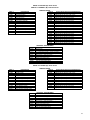
1
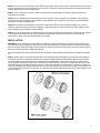
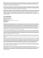
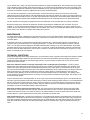
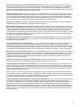
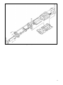
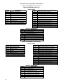
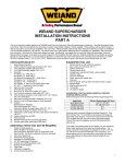
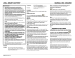
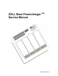
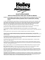
HOLLEY SUPERCHARGER
INSTALLATION INSTRUCTIONS AND TECHNICAL MANUAL
CAUTION: All superchargers and turbochargers increase the combustion pressure and temperature within an engine.
This puts additional loads on pistons, rings, bearings, crank, rods, and cylinder walls. All of these
components are capable of withstanding substantial increases in combustion pressure under proper
conditions.
In order to avoid potentially severe engine damage, it is critical that the timing and fuel mixture are correct. Detonation (spark
knock) caused by excessive ignition timing, or too high of a compression ratio and/or a lean condition in the carburetor can
destroy pistons, rings, and bearings in a short period of time. These conditions coupled with high engine rpm can literally
destroy an engine. Engine speeds in excess of 6,000 rpm are totally unnecessary with a blower, and can be extremely
detrimental. A roots supercharged engine will make maximum torque at a relatively low engine speed.
The Holley Powercharger is intended for use on engines with compression ratios of up to 9.50:1 with a maximum blower
pressure of 5-6 psi. Higher boost pressures will require lower compression ratios or a boost retard.
The Powercharger is available in three different blower sizes, 144 cu.in./revolution, 174 cu.in./revolution and 250
cu.in./revolution. The 144 and 174 blowers are used in low profile applications and the 250 blower is a taller higher performance
blower.
See the operation section of these instructions for details of distributor timing and carburetor modifications.
These instructions are general installation instructions for all versions of the Holley Powercharger. At the end of these
installation instructions there is a technical manual which outlines how the blower works and how you can get the most out of the
Holley supercharger.
The supercharger is complete in this kit. The pulleys are sold separately. For Powerchargers a different size driven pulley (the
upper pulley) is required for different displacement engines, so the correct pulley must be purchased separately. See your
Holley supercharger dealer for applications and part numbers.
The automotive versions of the 250 Powercharger include the 2-4 barrel carburetor adapter (#93151). The single 4 barrel
adapter is also available (#93150).
The supercharger, when installed correctly, will not cause any damage to an engine in good operating condition, as long as
engine knock, or ping, is controlled. The supercharger should not be used on any engine that is not in good operating condition,
or that does not have adequate oil pressure.
Before you begin installation of your new supercharger there are some additional Holley products you may wish to consider:
Boost Gauge, Part no. 90520: This extremely high quality gauge tells you engine vacuum or boost pressure at a glance.
Designed to be used with the Holley system the gauge reads 0-30 inches of vacuum and 0-15 psi boost.
Fuel Line Kit, Part Nos. 93171 and 93172: Fuel line kits for dual side mounted Holley carburetors. The kits include hard line
sets for both carburetors with fuel block and fittings. #93171 is for mechanical secondary carburetors and #93172 is for vacuum
secondary carburetors. Single Holley carburetor fuel lines are also available, 93178 for mechanical secondary carburetors or
93179 for vacuum secondary.
Camshafts for Street Superchargers: The Camshaft (P/N 01006LSK) for the small block Chevrolet is a streetable cam with a
reasonable idle, plenty of vacuum and very good mid and top range power. The Ultra Charger Cam for big block Chevrolet has a
slightly rough idle, acceptable vacuum for most street applications and outstanding mid and top range power. Both cam kits
include special valve springs and lifters. The Camshaft (P/N 02006LSK) also includes retainers.
Linkage Kits, Part no. 90747: Holley offers a kit that mounts between the supercharger housing and the carburetor and allows
the late model GM factory throttle cable to be relocated to work with the repositioned carburetor on the supercharger. It also
accepts the transmission kickdown cable. This kit can be used on all single carburetor Powerchargers.
Linkage Kits, Part no. 93167 (250 Powercharger): Holley offers linkage kit for the 250 Powercharger with two side mounted
Holley carburetors. The rigid linkage synchronizes the two carburetors.
Linkage Kits, Part no. 93197 (250 Powercharger): Holley offers linkage kit for the 250 Powercharger with two fore and aft
Holley carburetors. The rigid linkage synchronizes the two carburetors.
Precautions before beginning installation: One of the most important aspects of an engine that is to utilize a supercharger is
its overall condition. The Holley supercharger is not a cure all for an ailing engine, and may cause an engine already in poor
shape to fail. The chosen engine should first be double-checked on the following points:
1. OIL PRESSURE. A supercharger increases cylinder pressure, which increases the loading on the connecting rod and main
bearings. As long as there is adequate oil pressure, no difference in bearing life should be expected. DO NOT ASSUME that
because the engine oil light does not come on that there is adequate engine oil pressure. We strongly recommend that your
engine be able to maintain a MINIMUM OF 20 PSI OIL PRESSURE AT IDLE, and more as engine RPM increases. THIS
SHOULD BE CHECKED WITH A GAUGE. Use of a slightly higher viscosity oil may be required. Do not resort to an “oil
thickening” additive to achieve the recommended oil pressure. Repair the problem before installing the Holley supercharger.
2. COMPRESSION RATIO, RING CONDITION, AND COMPRESSION PRESSURE. An engine being considered for a
supercharger should not exceed 9.5:1 compression ratio. Exceeding this limit requires a reduction in the amount of boost, water
injection, race fuel, or excessive spark retarding to prevent detonation (engine knock) and its destructive results on the engine.
Performing a compression or leak down test before installation is also a good idea. This will help determine ring condition and
valve seating. An engine with one or more cylinders reading 10-15% lower than the rest should have this condition checked and
repaired before supercharger installation. Check the factory service manual for proper procedures and readings.
EFFECTIVE COMPRESSION RATIO CHART
Comp.
Ratio
7.0
7.5
8.0
8.5
9.0
9.5
10.0
10.5
11.0
2
8.0
8.5
9.1
9.7
10.2
10.8
11.4
11.9
12.5
4
8.9
9.5
10.2
10.8
11.4
12.1
12.7
13.4
14.0
6
9.9
10.6
11.3
12.0
12.7
13.4
14.1
14.8
15.5
Blower Boost Pressure (lbs. per square inch)
8
10
12
14
16
10.8
11.8
12.7
13.6
14.5
11.6
12.6
13.6
14.6
15.7
12.4
13.4
14.5
15.6
16.7
13.1
14.3
15.4
16.6
17.8
13.9
15.1
16.3
17.6
18.8
14.7
16.0
17.3
18.5
19.8
15.4
16.8
18.2
19.5
20.9
16.2
17.6
19.1
20.5
21.9
17.0
18.5
20.0
21.5
22.9
18
15.3
16.7
17.8
18.9
20.0
21.1
22.2
23.4
24.5
20
16.2
17.8
18.9
19.8
21.2
22.4
23.6
24.8
26.0
22
17.0
18.6
19.8
20.9
22.4
23.6
24.8
26.2
27.5
24
17.9
19.5
20.9
21.9
23.6
24.8
26.0
27.6
28.9
The above chart shows the effective compression ratio of your engine, which combines the static compression ratio with the
amount of supercharger boost. Note that for most street applications with 92 octane pump gas, you should keep your effective
compression ratio below about 12:1. On marine engines, you should keep the effective compression ratio below about 11.5:1.
For added protection against possible engine detonation (knock), we strongly recommend using a boost retard system, such as
Holley P/N 91070.
3. RADIATOR CAPACITY. The Holley supercharger, under boost conditions, permits your engine to convert air/fuel mixture into
heat at a greater rate than stock, which produces more heat and, therefore, more power. Sustained periods of wide open throttle
driving will raise the temperature of your engine. If your radiator is sized correctly for your stock engine, it should pose no
problem with the supercharger. Where radiator cooling capacity may be marginal, we recommend that, prior to the installation of
your Holley supercharger, you increase the cooling capacity, either through enlarging the radiator or adding auxiliary fans.
4. IGNITION QUALITY. Any engine being considered for use with a supercharger should undergo a general tune-up prior to the
installation. Any ignition component in questionable condition should be replaced before supercharger installation. Missing,
cross-firing, or electrical leaks should be carefully checked and repaired. Modification to the spark advance curve may also be
necessary as discussed in the operation section of these instructions. We do not recommend a point type distributor on a blower
motor, use only and electronic distributor.
DISASSEMBLY
STEP 1. Drain the cooling system. Remove the upper radiator hose and put it aside. Remove the thermostat housing and the
thermostat. Disconnect the heater hoses that are attached to the intake manifold. Scrape any gasket material from the
thermostat housing. Disconnect the battery.
2
STEP 2. Loosen and remove all accessory drive belts from the engine. Remove the alternator or alternator brackets if any of the
brackets are attached to the intake manifold. Remove any other accessory or accessory brackets that are attached to the intake
manifold. Remove the fan from the water pump.
STEP 3. In many cases it will be easier to install the lower pulley to the crankshaft if the radiator and/or the fan shroud is
removed from the vehicle.
STEP 4. Remove the distributor and spark plug wires from the engine, noting the position of the distributor and rotor before
removal to permit easy reinstallation of the distributor. If the distributor uses a separate coil mounted on the intake manifold,
remove the coil and its mounting bracket.
STEP 5. Disconnect the throttle linkage or cable from the carburetor. Disconnect the transmission linkage, if any, from the
carburetor. Disconnect the fuel line from the carburetor. Temporarily plug the fuel line. Disconnect any other linkage or wiring
that is connected to the carburetor or intake manifold.
STEP 6. Remove the bolts holding the intake manifold to the cylinder heads and remove the intake manifold. Remove all traces
of the old gaskets and sealer from the cylinder heads and cylinder block. If the same carburetor is to be used with the
supercharger, remove it from the intake manifold and set it aside.
INSTALLATION
WARNING: Be very careful that no foreign objects are allowed to enter the supercharger. Anything that comes between the
rotors and the housing or between the two rotors can cause serious damage to the supercharger. Do not remove the covering
from the outlet port of the supercharger, until just before it is bolted to the intake manifold. Do not remove the covering from the
intake port, until the carburetor is ready to be bolted on.
250 Powerchargers use a Gilmer (toothed) belt to drive the blower. See the supplemental instructions for details of the specific
kit.
STEP 1. (Powercharger). Remove the bolts that secure the crankshaft pulley to the damper. The center bolt from the damper
must also be removed on small block Chevrolet V8s. Install the supplied supercharger drive pulley together with any spacers
that are supplied with the kit inside of the stock stamped steel crankshaft pulley. Fit the pilot on the pulley or spacer into the
center of the stock steel pulley, and the pilot of the drive pulley into the spacer, if there is one, and align the bolt holes. Put the
supplied bolts through the pulley and spacer (if there is one) into the crankshaft. Use thread sealer on these bolts. Tighten the
bolts. The small block Chevrolet kits require the removal of the center bolt that secures the harmonic balancer to the engine, but
on other engines the center bolt is not removed. On small block Chevrolet kits install the supplied center bolt and tighten it to 75
ft./lbs. See Figure 1.
Figure 1
3
STEP 2. Prepare the intake manifold for installation. Install the thermostat into the manifold, and bolt on the thermostat housing.
Use a new thermostat gasket when installing the thermostat housing and always use a thermostat or a water restrictor. 250
Powerchargers include a new thermostat housing which is mounted on the front face of the intake manifold. The thermostat
housing has an “O” ring seal, so no gasket is required.
Remove the heater hose fitting(s), water pump bypass fittings and the temperature gauge sender from the old intake manifold
and install in the similar location in the Holley intake manifold. Install pipe plugs in the unused water opening(s) in the manifold.
The 1/8" pipe threaded hole on the manifold is for a manifold pressure gauge and the distributor vacuum advance/boost retard.
If a gauge is not being used, this hole should be plugged with a 1/8 NPT pipe plug.
STEP 3. Install the supplied new intake manifold gaskets. Use the original intake manifold hold down bolts. If the distributor goes
through the intake manifold, check that it fits correctly before tightening the manifold bolts. Leave the distributor in place while
the bolts are being tightened. Tighten the intake manifold hold down bolts in the sequence specified by the manufacturer and to
their specified torque. It is important to follow the tightening sequence and torque readings accurately to ensure that the
manifold is not distorted. In some cases where there is a tight clearance next to a manifold bolt, 12 point or socket head screws
may need to be used.
TOOLS REQUIRED:
Ratchet or Speed Handle
Torque Wrench (100 lb./ft.)
Sockets 7/16”, 1/2”, 9/16”, & 5/8”
Extensions 3” or 4”
Open End/Box Wrench 3/8”, 7/16”, 1/2”, 9/16”, & 5/8”
Allen Wrench 3/8”
Gasket Scraper
Small block Chevrolet and Ford blower kits with the 144 cid blower have provision for an exhaust crossover for manifold heat
and exhaust gas recirculation (EGR). There is a mounting pad on the Holley intake manifold for the EGR valve. A block off plate
is installed on the pad that can be removed to mount the EGR valve if it is being used. The exhaust gas for the EGR valve
comes from the exhaust heat crossover in the intake manifold. If you are not using the EGR valve and if you do not use the
vehicle in extremely cold conditions, the exhaust crossover passage can be blocked with steel shims at both cylinder heads. The
driveability of the supercharger is very good without exhaust heat under all but the very coldest conditions. If you block the
exhaust heat crossover, also secure the exhaust heat valve in one of the exhaust manifolds in the open position. Blocking the
exhaust heat will provide approximately 10-15 HP gain on an average V8.
The 250 Powercharger with Gilmer belt drive has a pop off valve mounted on the right hand side of the intake manifold. Install
the pop off valve onto the intake manifold after the manifold is bolted to the engine. Check to see that the gasket is attached to
the back side of the pop off valve plate. Place the plate on the manifold and then screw in the two studs. Put the two springs
over the studs. Put the spring retainers into the outer end of the springs and screw the lock nuts onto the studs. Tighten the nuts
until you have a spring height of 1-1/2" on each spring.
STEP 4. Reinstall radiator if removed. Connect upper radiator hose to the thermostat housing and connect the heater hose(s).
You may need to use a different upper radiator hose to clear the supercharger drive housing. Fill the cooling system and check
for leaks.
STEP 5 (Powercharger). Prepare the supercharger for installation. Remove the bolt and washer on the end of the supercharger
input shaft. Remove the plastic shipping cover from the input shaft. You may find some oil residue around this area. This is gear
oil, which has leaked down the keyway of the input shaft. Put the drive pulley you have chosen and the 3/16 x 3/16 x 3/4 key on
to the input shaft. Secure with the bolt and washer. We suggest that you use a little Loctite on the pulley retaining bolt threads.
Also put some gasket sealer on the underside of the washer to prevent oil seeping out of the keyway. Torque the bolt to 30
ft./lbs. Use a clean rag between the rotors to keep the shaft from turning. Make sure to remove the rag after tightening.
Install the carburetor adapter on the 250 Powercharger. Install the gasket and screws supplied with the adapter. Tighten the
screws to 10 ft./lbs. After installing the adapter feel inside of the rotor housing to be sure that the ends of the eight screws do not
project through into the bore of the rotor housing.
To check the oil level, first tilt the supercharger forward to be sure that oil flows around the front bearing. Then set the
supercharger flat on a bench. Use the new oil level sight window to check the level. (See Figure 2.) The oil level should be up to
the bottom of the hole. If the oil level is low, fill with SAE 80-90 gear lube. Because of the internal baffles inside of the gear case,
the oil that is poured into the blower will go in very slowly. After pouring more oil into the fill hole wait two minutes before
checking the fill level.
4
Figure 2
STEP 6 (Poly-V belt). A bracket for the idler is attached to the drive housing of the supercharger. There are two basic idler
assemblies that are used on almost all kits. The idler for blowers with the standard input location has one spring loaded idler
bolted to it (see Figure 3). The idler for blowers with an offset input (used on Ford V8 engines to clear the distributor) have a
fixed idler and a spring loaded idler. The spring-loaded idler is bolted to the cast mounting bracket (see Figure 4). Both types of
mounting brackets have a number of holes in them for locating Only two of the holes are used for the mounting bolts for the
spring loaded idler/tensioner. These holes allow for several different locations for the idler assembly, and are used for different
sizes of driven (upper) pulleys.
The idler assembly should be bolted to the support bracket with the two Allen head screws supplied with the kit. The preliminary
location for the spring loaded idler is shown on the supplemental instructions for the particular blower kit. The two screws that
hold the spring loaded idler in place go through either two holes in the upper row or two holes in the lower row on the support
bracket and then screw into either the upper or lower two tapped holes on the idler mounting pad. Mount the idler and tighten
the screws, but do not use the thread sealer at this time. The supercharger should now look like Figure 3 or 4. Be sure that the
bolts securing the support bracket to the drive housing are also tight. The nut on the threaded rod extending from the end of the
idler assembly should be fully tightened to pull the idler all of the way in.
5
Figure 3
Figure 4
STEP 6 (250 Gilmer belt). The idler support assembly bolts to the front of the intake manifold. The support plate is secured with
four 3/8-16 flat head Allen screws. The screws go through the idler support plate, through the four aluminum spacer tubes, and
screw into the front of the intake manifold. Tighten the screws to 25-35 ft/lbs. (See Figure 5.)
6
Figure 5
STEP 7. Remove cardboard cover from the bottom of the supercharger and clean the surface. Check the flatness of the intake
manifold by placing the supercharger on the manifold and rocking it. If the manifold is flat, the supercharger will not rock. On
older or rebuilt engines there may be some rocking. If there is more than .010" rocking, the supercharger housing may become
distorted when it is bolted down. This can be checked by placing a feeler gauge between the bottom of the rotor housing and the
intake manifold or by using a straightedge.
A gasket is used between the intake manifold and the blower on all blowers. The 250 Powercharger formerly used an O-Ring
set into a groove in the top of the intake manifold. This has been replaced with a gasket for better sealing. Some intake
manifolds may have a machined groove for an O-Ring, but these will seal correctly with the supplied gasket.
For Powerchargers, install the four 7/16" x 7" bolts, or three 6-3/8" and one 8" studs for blowers with offset input shafts, through
the mounting holes in the supercharger. Put the supplied flat washers under the heads of the bolts. Use thread sealer on these
bolts. Tighten the bolts or nuts. Do not tighten the bolts or nuts to over 10 ft./lbs., or the threads in the intake manifold may strip,
or the blower may lock up.
If the manifold is not completely flat, there will be an increase in the torque required to turn the blower, usually at ninety degree
intervals in each complete revolution of the input shaft. If the torque to turn the input shaft is not over 25 in./lbs. at these tight
spots, the Teflon seals will wear in during the first few miles of driving. If the turning torque is over 25 in./lbs., then loosen one
hold down bolt at a time to see which one is causing the blower to bind up. Leave this one bolt at a lower torque level, but at
least 5 ft./lbs. for the Powercharger, while the blower is being run in and tighten it later when the Teflon has seated.
STEP 8. Reinstall the stock brackets and accessories that attach to the intake manifold. The 144 and 174 manifolds are
equipped with mounting bosses to accommodate most standard OEM parts from your stock manifold. . Because of the larger
size of the 250 Powercharger it may be necessary to modify some brackets and accessories. Connect heater hoses and any
other plumbing that connects to the manifold.
STEP 9 (Poly-V belt). Install and tighten the accessory belts. Install the Poly-V belt over the lower drive pulley, driven pulley,
and idler pulley(s). Loosen the nut on the threaded rod on the back of the idler to let the idler pulley tension the belt. When the
nut is loose, measure the distance between the pulley support and the end of the fixed tube of the idler as shown in Figure 6.
This dimension should be between .30" and .50" (5/16" and 1/2"). If the measured dimension is outside of this range, the idler
will have to be moved in or out. Due to manufacturing tolerances on belts, the final position of the idler may be different than the
preliminary location.
After the idler is correctly located and the dimension is between .30" and .50", tighten the nut on the threaded rod to remove
tension from the idler. Then apply the supplied thread sealer to the two mounting screws and tighten securely. Remove the nut
from the threaded rod and leave it off.
On some late model engines the idler may interfere with the alternator. If this happens you will need to use a slightly longer
alternator belt.
7
Figure 6
STEP 9 (Gilmer belt). Install all belt-driven engine accessories and drive belts before installing the blower drive. Put the 5/8-11
socket head bolt through the center of the idler pulley assembly. Put the bolt through the slot in the idler support plate and put
the nut on the back side of the plate. Align the nut with the slot and tighten the bolt finger tight with the pulley slid as far inboard
as possible. Put the blower drive belt over the drive and driven pulleys and over the idler. Make sure that the belt is seated in the
grooves in the upper and lower pulleys. Slide the idler pulley out until there is about 1-1/2" of slack in the belt when the blower is
cold. Tighten the bolt. The belt tension will be rechecked later after the engine has been warmed up. There must be a minimum
of 1/2-5/8" slack in the belt when the engine is hot, or the blower or crankshaft can be over stressed. (See the included Gilmer
Belt Installation and Adjustment Instruction sheet for more details.
STEP 10. Install the fan if required. It may be necessary to put a fan spacer between the fan and the water pump so that the fan
will not hit the supercharger drive belt. Allow at least 3/8" between the fan blades and the rear side of the radiator and fan
shroud to avoid contact. You may need to modify an available fan spacer to achieve proper fan clearance. We do not
recommend using a large viscous drive clutch fan with a blower. The addition of a fan spacer to the system together with the
higher engine speeds frequently used with a supercharger seems to aggravate the possibility of breakage of the water pump. A
lighter weight flex fan is recommended, particularly for truck usage. Also make sure that the pump pulley, spacer and fan
assembly are concentric and balanced.
Some applications may not have enough room for a conventional fan with the supercharger installed. In this case electric
cooling fan(s) can be used.
STEP 11. Remove the cardboard cover(s) from the top of the blower. Install the carburetor(s) on the top of the supercharger. If a
spreadbore is being used install a carburetor gasket at least 1/8" thick, preferably the stock GM carburetor spacer/insulator. This
spacer/insulator assures a complete seal between the carburetor and the top of the blower. Some gaskets have a channel at the
back that can cause a vacuum leak. Check the carburetor gasket and spacers that you are using to be sure that they fully seal
to both the bottom of the carb and to the top of the blower. Holley spread bore carburetors will not always seal to the top of the
Holley blower using standard gaskets. If there is an air leak between the carburetor and the blower, the engine will not run
correctly and it will probably be lean. If you are using the Holley #90747 throttle cable bracket, install it between the carburetor
and the blower when the carburetor is installed. Be sure to use a cork or rubber gasket between the air cleaner and the
carburetor, or excessive noise may result.
Check to see that the secondary throttle blade of the spreadbore carburetor can open fully without hitting the blower. The 1/8"
gasket or spacer should be enough to avoid this problem, but it should be checked to be sure. If a Holley carburetor with the
REO accelerator pump is used, it may be necessary to use two gaskets, so that the pump will not hit the supercharger housing.
Check all carburetor secondary throttle plates in the full open position to make sure they don’t hit the blower housing. If they do,
space the carburetor up with the appropriate spacer or gaskets. If you have adequate hood clearance it’s not a bad idea to
utilize a non-metallic spacer between the carb and blower as a heat insulator. These are available from several manufacturers.
8
250 Powerchargers use either one or two 4 bbl carburetors, depending on the carburetor adapter installed on the blower. The
single carburetor installation is similar to the smaller blowers, as described above.
For 250 Powerchargers with two carburetors, the mounting pad is drilled so that the carburetors can be mounted either fore and
aft or side saddle. The only carburetors that will fit when mounted fore and aft are the Holley 1850 or other similar model
Holleys. All other carburetors must be mounted side saddle.
STEP 12. Connect the throttle linkage to the carburetor. Some cable throttle linkages and most rod-type linkages will require
reworking to properly operate the throttle lever. Be sure that the carburetor is wide-open when the accelerator pedal is pushed to
the floor, and that the throttle closes fully when the accelerator pedal is released.
Vehicles equipped with a TH200, TH200-R4, TH700-4R, C-3, AOD, or A4LD transmission have the shifts controlled by a
mechanical linkage or cable between the carburetor and the transmission. This linkage or cable must be connected to the
carburetor in exactly the same manner as the stock vehicle for the transmission to operate correctly. On GM transmissions the
proper operation of the throttle cable is essential for correct operation and life of the transmission. Vehicles equipped with
TH350, C-4, C-5 or C-6 transmission use a mechanical linkage or cable between the carburetor and transmission to control
transmission kickdown. These cables and linkages must be adjusted for correct operation of the kickdown at wide-open throttle.
The TH400 transmission uses an electric switch to control kickdown.
For GM cars with a single carburetor Holley offers a special cable bracket (#90747) that mounts between the supercharger
housing and the carburetor. It allows the late model GM factory throttle cable (or kickdown cable), transmission cable, and
cruise control cable to be relocated to work with the repositioned carburetor on the supercharger.
For 250 Powerchargers with two carburetors Holley offers a throttle linkage kits. #93167 is for 250 Powercharger with side
saddle carburetors. This kit uses a bellcrank on the side of the blower to connect to the vehicle throttle linkage.
If your vehicle is equipped with a TH-350 or TH-400 automatic transmission, the shifts are controlled by a vacuum modulator
that senses manifold vacuum, while kickdown is controlled by linkage, a cable or a switch. In most cases the vacuum modulator
will work satisfactorily when hooked up to the carburetor.
STEP 13. Run a fuel line from the fuel pump to the carburetor. Be sure that the fuel line is away from the exhaust or any moving
parts and that it is well secured. Use only approved fuel line. Install a new fuel filter between the fuel pump and the carburetor.
See the Holley Supercharger Technical Manual for fuel line and pump sizes. Holley's fuel line kit #93171 can be used for side
mount Holly double pumper carburetors and #93172 can be used for side mount Holley vacuum secondary carburetors.
STEP 14. Recheck the distributor and install the spark plug wires. Be sure that the distributor is installed in the same position
that it was in when it was removed. Use the distributor hold down clamp from the old manifold. A stud can be used to secure the
hold down clamp. Incorrect ignition timing can cause backfiring, which may result is severe blower damage. See the Holley
Supercharger Technical Manual for timing tips.
STEP 15. Connect power brake vacuum hose and other vacuum hoses to the vacuum fittings on the carburetor or to the port on
the passenger’s side of the rotor housing under the carburetor. (The pipe plug must be in this port if it is not connected to a
vacuum line.) The power brakes must not be connected to the intake manifold. The crankcase vent hose (or the PCV valve)
must have a separate vacuum connection to the carburetor or to the port on the rotor housing. The crankcase vent must not be
connected to the same vacuum fitting used for the power brakes or for any other vacuum accessory. All other vacuum needs
can be connected to one fitting, but the crankcase vent must be separate. The power brakes and other accessories will not work
correctly if they are connected to the same fitting as the crankcase vent.
If a manifold pressure gauge (boost gauge) is used, it should be connected to the intake manifold. This gauge, part number
90520, is available from Holley. If a boost retard system is used, it also connects to this port. Use a T fitting if both a gauge and
boost retard are connected in this location.
STEP 16. Install an air cleaner(s). The engine should not be run for any length of time or the vehicle should not be driven
without an air cleaner. Otherwise dirt particles may damage the supercharger and will damage the engine.
STEP 17. Start the engine and let it idle. Look for gasoline, coolant, oil or vacuum leaks. There may be a noise similar to a
misadjusted tappet coming from the supercharger, if there is rubbing between the Teflon seals and the housing. This noise may
take a few thousand miles to go away as the Teflon seats. Check that the blower drive pulley on the crankshaft is running true
and that the blower drive belt is also running true. Set the spark timing.
STEP 18. Let the engine idle for 5-10 minutes before driving the vehicle. (If the blower is being installed on a newly built engine,
the engine should be broken in the normal manner. (See your cam instruction manual.) Do not use wide-open throttle, until you
are sure the engine, transmission and BRAKES are working properly. Keep the engine speed down for the first 20 minutes of
driving to allow the Teflon to properly seat. Once the engine is warm, and the Teflon is properly seated, give the vehicle a few
full throttle bursts. The boost should come immediately, rising to its peak level above 4,000 engine rpm, if you’ve selected the
proper size driven pulley for your engine displacement. If the boost reading is low, check the low boost section of the Technical
Manual.
9
With a Gilmer belt drive, check the tension of the drive belt when the engine is up to operating temperature. There must be a
minimum of 1/2-5/8" slack in the belt when the engine is hot, or the blower or crankshaft can be over stressed. If you fracture the
blower-input shaft housing because the belt was too tight, it will not be covered by warranty.
After a short test drive, check again for leaks, particularly for gasoline leaks.
TECHNICAL MANUAL
The purpose of this section of the installation instructions is to provide the owner with an overview of mechanically driven
superchargers - their operation, characteristics and advantages. This section points out what to expect from your blower and
how to get the most from your blower in longevity and performance.
The Holley Powercharger 144 and 174 blowers have good efficiency at speeds and pressures normally used on the street.
These Holley blowers are not designed as a full race blower, but rather a compact and lightweight system, which will install on
your engine with little or no modification
OPERATION
When driving a vehicle equipped with the Holley supercharger you will have more engine torque available at all engine speeds.
It will be very responsive to accelerator pedal movement and will not have any of the lag associated with other types of
superchargers.
If you have fitted a manifold vacuum/boost gauge, you will notice that under most driving conditions, the gauge will remain in the
vacuum range. It will show a manifold boost from about half to wide-open throttle (WOT). The manifold boost at WOT will
change with engine speed, being the greatest at high engine speeds. There will be enough boost in the low to mid speed range
to greatly improve the acceleration of the vehicle, however.
There will be very little noise from the supercharger, except at WOT. Since the Poly-V belt is quiet, it does not add noise to the
blower, as a Gilmer belt does. There may be some additional noise from a new blower, while the Teflon seals are seating in.
The 144 and 174 Powercharger kits are designed to use a single four-barrel carburetor. The original stock carburetor used on
the engine can be used with the supercharger. The stock size carburetor will work well with the supercharger, although a higher
flow capacity carburetor will usually increase top end power. Stock carburetors are usually more than adequate up to 4,500 to
5,000 rpm with 5-6 psi boost.
The 250 Powercharger uses either one or two four-barrel carburetors. See the carburetor section of this manual for carburetor
flow recommendations.
There may be a flat spot or hesitation when the throttle is opened quickly with the supercharger, particularly with larger
displacement engines. This can be corrected by increasing the volume of the accelerator pump shot. On a Holley carburetor, the
REO large accelerator pump kit can be installed.
HOW IT WORKS
All roots type superchargers function in a similar fashion. The minor differences are in the shape and number of lobes used. A
roots type blower is an air pump. Air from the carburetor side is drawn into the housing by the rotors, pushed to the outlet side,
and compressed in the manifold. Each complete revolution of the blower will produce four pressure pulses. These occur when
the rotor tips pass the blower outlet port edge. The GMC 71 series blowers have three lobes and the rotors are helically cut.
Both these features serve to somewhat quiet the pulses, but make for a more complex and expensive blower.
The quantity of air that the supercharger will move and the displacement of the supercharger is determined by the volume of air
that is trapped between the rotor and the housing. Four of these volumes of air are moved every revolution of the blower. If the
quantity of air that is pumped by the blower is more than the quantity of air that would normally be drawn in by the engine, the
additional air will pressurize the intake manifold and produce boost.
The reason a large engine can produce more torque and power, all else being equal, is that it can convert more air/fuel mixture
to energy per revolution than a small engine. A blower simply assists a small engine in “breathing” like a big one. The pressure
ratio of the blower is roughly proportional to the ratio of power increase.
DETONATION ELIMINATION
The increase in engine output with a Holley supercharger does have the potential of causing serious engine problems in one
area—detonation, knock, or engine ping. The blower will increase the effective compression ratio of the engine. A 7 psi blower
pressure will raise a 7.5:1 compression ratio to an effective 9.8:1 compression ratio. An 8.5 compression ratio will be raised to
an effective 11.2:1, and a 10.0:1 compression ratio will be raised to an effective 13.5:1 ratio.
10
This higher effective compression ratio of the engine makes detonation a potential problem, particularly with the lower octane
fuels that are now available. There are several methods that may be used to keep detonation under control, but it is essential
that there be no detonation. A very limited amount of detonation will result in severe damage to the engine. A supercharged
engine will be much less tolerant of detonation than a normally aspirated engine.
The basic means of controlling detonation are compression ratios, spark advance, fuel mixture and water injection. A lower
compression ratio is the best way to control detonation, but this may require building a special engine. For normal street use
with the boost pressure in the 5-7 psi range a compression ratio of up to 8.5:1 can be used, although some spark retard may be
needed.
Spark retard will always reduce detonation, although it is best for the spark to be retarded only when the supercharger is
producing boost and to have more spark advance at part throttle. This improves the part throttle performance and the fuel
economy. There are several ways to reduce the spark advance under boost without reducing the part throttle spark advance.
Holley offers an electronic boost retard unit (P/N 91070). This unit will retard the timing from 1° to 3° (adjustable) per pound of
boost. It works with any electronic trigger ignition system except MSD. MSD also manufactures a unit, the Boost Timing Master
that retards the spark under boost.
We have achieved our best results with 12 to 20° of initial lead with a total lead of 32 to 36°. The advance should be in by 2,000
to 2,500 rpm. Excessive ignition timing will not produce appreciably better performance and can be potentially very harmful.
A richer fuel mixture will reduce detonation, but will have only a limited effect compared to spark retard. It is always desirable to
have the WOT mixture on the rich side for any supercharged engine to reduce piston failures.
Octane booster additives can give a substantial increase to the octane of pump fuel. A series of tests were run at San Diego
State University where different “octane booster” additives were added to 92 octane Super Unleaded gasoline. The octane
number of the fuel was measured on a supercharged CFR engine. The highest measured octane was 104.5 for Moroso 2
additive. They mixed 16 oz. of additive to 22 gallons of gasoline. This is a gain of 12.5 octane numbers. Other additives that
were checked gave smaller, but still significant gains in octane. This, however, can be expensive. The Moroso 2 additive in the
concentration tested, adds about $0.65 to the cost of each gallon of gasoline. Higher octane leaded “racing” gasolines with
octane ratings of 107 or higher are also available in most areas, but these gasolines are also very expensive. Generally both the
racing gasolines and the octane booster additives are too expensive to consider for the everyday street driven vehicle.
ENGINE COMPONENT RECOMMENDATIONS
It is not necessary to build a special engine to go with a Holley supercharger if the boost is limited to the 5-7 psi range. Above
that boost the engine will need a lower compression ratio. Even a specially built engine does not need to use O-rings between
the head and block, dead soft copper gaskets, or other “tricks” used with blown engines. The engine requirements for using a
blower are much simpler than most people expect. Good oil pressure, proper cylinder sealing (rings and valves) and oil control,
an adequate radiator - usually the factory original, an ignition system in proper working order, and a properly sized carburetor
are all that one needs to effectively use a supercharger.
For a higher boost (9-12 psi) engine, other than forged low compression pistons, there are few special parts required. It is not
necessary to use forged crankshafts or four bolt bearing caps on a blown engine, since the high loading of these parts comes
from high engine speeds, not high cylinder pressures. A supercharger produces extra power in the normal speed range and
does not have to be turned to high engine speeds, as is normally required for a high output unblown engine. We have found that
Felpro head gaskets with a wire sealing ring work very well in a blown engine. We have also had very good results with Lunati
Pro-Series or Sealed Power Speed Pro Plasma Moly-coated piston rings.
CAMSHAFTS
High overlap camshafts are actually detrimental to a supercharged street engine’s performance. The longer the exhaust and
intake are open at the same time, the more usable air/fuel mixture is blown out the tailpipe. We have found that a cam with a
114º lobe centerline works best on a street driven vehicle. When choosing a cam profile to work well with a blower, moderate lift
and duration are desirable, but excessive overlap is undesirable. Cams generally produce additional power only at higher engine
speeds usually above 4,500 rpm. If higher engine speed performance is not desired, a stock cam is actually better than a
modified cam.
Holley offers a line of street supercharger cams for small and big block Chevrolet engines. The Camshaft (P/N 01006LSK) for
the small block Chevrolet is a streetable cam with a reasonable idle, plenty of vacuum, and very good mid and top range power.
The Camshaft (P/N 02006LSK) for the big block Chevrolet has a slightly rough idle, acceptable vacuum for most street
applications, and outstanding mid and top range power.
Valve springs are more critical on a blown engine than on a normally aspirated one, since you have supercharger boost
pressure acting on the backside of the intake valve, trying to push it open. You need stronger valve springs with a supercharger.
Special valve springs are included with all Holley cams.
11
CYLINDER HEADS
Enlarging and polishing the intake ports of a cylinder head is of medium value on a supercharged street engine. While it cannot
hurt performance, whatever gain you may see from this type of modification may not be worth the trouble and expense. A free
breathing exhaust system has always been a big performance plus, and is a good idea with a supercharged engine. Engines
with small stock exhaust ports (such as 302 and 351-W Fords) will improve with opened up exhaust ports. Headers do not
provide as great an increase with a blown engine as on a normally aspirated engine, but do help performance. Larger valves
only increase the engine output above 4,500 rpm or so, but they do not hurt performance at any speed. Increasing the exhaust
valve size usually give greater increases in performance than increasing the intake valve size. Expect to see a boost drop with a
good flowing set of heads. Despite the boost drop the engine performance will increase.
IGNITION SYSTEMS
A “hot” ignition system, especially one equipped with a knock sensor, will be an asset to a supercharged engine, especially
when producing more than recommended boost. A capacitive discharge, electronic or high-energy system will be a very
worthwhile addition to your engine. If you are installing a blower on a late model engine with computer controlled spark advance
it is necessary that all elements of the engine computer control system be operational or else the computer may not provide the
correct spark advance. If this is not possible it will be necessary to replace the computer controlled distributor with an earlier
model for the same engine that has mechanical spark advance in the distributor. You can use either an OEM distributor or an
aftermarket performance distributor. We have found that for all of the engines that we have dyno-tested that the best power is
obtained with 32 degrees of total spark advance, with the entire advance coming in by 2,800 rpm. This is the maximum power
with 108-octane race gasoline, you will probably not be able to use this much advance with pump gasoline. Our tests have
shown that dropping the total spark advance back to 25 degrees results in a loss of only two percent of power and torque up to
4,000 rpm and four percent of power and torque at 5,500 rpm. For this small loss in power there will be a considerable reduction
in detonation. With a boost retard system, such as the Holley #91070 you can use full advance in the distributor and have the
spark retarded when the boost comes in.
CARBURETION
Necessary carburetor modifications are minimal with the Holley blower. The installation of a blower increases the distance from
the carburetor to the cylinder, which makes a larger volume accelerator pump necessary, If you are using a Holley carburetor, a
50cc accelerator pump kit (Holley PN 20-11) works well. A richer mixture is always desirable on a blown engine to control
detonation. The mixture of the secondary side of the carburetor and the WOT or power valve mixture are the more important.
Late model “emission” carburetors tend to be jetted much leaner than non-emission or “universal” carburetors. These
carburetors need larger jets on both the primary and secondary sides.
We have run tests with all makes of four barrel carburetors on supercharged engines and gotten good results with all of them.
OEM carburetors will work well on engines that are used in the low and mid speed range. These carburetors usually have a
lower air flow capacity than is needed for high engine speed running or for boost of over 7 psi. If a new carburetor is being
purchased for a supercharger, we would recommend a Holley carburetor, mainly because of the wide range of sizes available
and the easy availability of jetting and other parts for these carburetors. Detailed information of the operation and tuning of
Holley carburetors is available in the book “Holley Carburetors and Manifolds” by Mike Urich and Bill Fisher published by H. P.
Publishing.
The rated flow capacity of a carburetor is a way of measuring carburetor size. It is the quantity of air flow through the carburetor
that gives a specified pressure drop across the carburetor: usually 1.5 inches of mercury for four barrel carburetors and 3.0
inches of mercury for two barrel carburetors: the higher the flow rating, the bigger the carburetor. Or, the bigger the carburetor
the lower the pressure drop across it at any given air flow. A carburetor can flow more air than its rated capacity, but when it
does so it has a greater pressure drop across the carburetor. The pressure drop through the carburetor reduces the pressure
into the supercharger and also reduces the boost pressure in the intake manifold. Therefore the bigger the carburetor the higher
the blower boost and the higher the maximum power. The problem with this is at the other end of the air flow range. Too big of a
carburetor will have low air velocity through the carburetor at idle and in low speed driving and will give poor driveability. The
required air flow capacity for a carburetor on a supercharged engine depends on the displacement of the engine and the boost
pressure desired. For single carburetor installations with boost in the 5-7 psi range we recommend that you consider the
following carburetor flow capacities:
Engine Displacement
300 CID
350 CID
Carburetor Capacity
650 CFM
750 CFM
400 CID
450 CID
850 CFM
850 CFM
Use the available carburetor size that is closest to what is recommended for your engine size. The carburetor capacities are for
5-7 psi boost. For higher boost levels (10-12 psi) the carburetor capacity should be about 15% larger. We strongly recommend
vacuum secondary carburetors for street use, since they provide better low and mid speed driveability than mechanical
secondary or “double pumper” carburetors. Air valve secondary carburetors like the Holley vacuum secondary carburetors are
normally available only up to 750 CFM capacity. Holley does make an 850 CFM vacuum secondary carburetor that is available
12
only on special order. Holley now offers a 950 CFM carburetor for higher boost applications. This carburetor is good for higher
revving big block engines and high boost 350 CID engines. If you need more than 850 CFM the best choice is the Holley 1050
CFM or 1150 CFM Dominator carburetors. These are basically race-only type carburetors and do not have good driveability on
the street. The Dominator requires an adapter plate since it has a unique bolt pattern.
If you are using two carburetors on a 250 Powercharger, we recommend that you use two 750 CFM vacuum secondary
carburetors for 350 cid engines and two 750 CFM double pumper carburetors for engines up to 460 cid. For larger engines two
850 CFM carburetors should be used. For very high output engines two 1050 CFM or 1150 CFM Dominator carburetors can be
used. These carburetors require special adapters and are basically race only carburetors with poor low speed performance.
The two carburetor mounting pads are tapped so that the two carburetors can be mounted either fore and aft or sideways. .
Because the height of the carburetor is raised when the Holley supercharger is installed, the stock air cleaner may not be
reusable, or you may wish to install an aftermarket air cleaner. In either case, when selecting an air cleaner, make sure it has
provision for PCV inlet and has as large a filtering area as possible. In this case, more is better. Be careful to allow enough room
for the choke on the carburetor to operate, without hitting the air cleaner.
MAINTENANCE
The Holley Powercharger is designed for long trouble-free service. The only area that should be checked regularly is the oil level
in the gear case. The oil level should be checked every 1,000 miles. If it is below the level of the check hole SAE 80/90 gear oil
should be added.
At the same time the oil is checked the drive belt should be examined. Ploy-V belts should be replaced, if it shows signs of
excessive wear on the inside surface or if it is slipping excessively. In normal use, the belt should last a minimum of 20,000
miles. You can detect excessive slippage by the black powdered rubber collecting on top of the idler assembly. Gilmer belts
should be replaced, if they show signs of excessive wear. In normal use, a Gilmer belt should last a minimum of 25,000 miles.
Be sure to check the Gilmer belt tension. There must be a minimum of 1/2-5/8" slack in the belt when the engine is hot, or the
blower or crankshaft can be over stressed.
TECHNICAL QUESTIONS
During the development of the Holley Powercharger, we encountered a variety of popular misconceptions and questions related
to roots type superchargers. Most of the questions arise as a result of lack of familiarity with supercharging in general. The
questions answered here apply to most supercharger systems, not just the Holley unit. Below are some of the most asked
questions and some answers.
What is the difference between a roots type supercharger and a centrifugal type supercharger? A roots (or positive
displacement) type supercharger pumps the same quantity of air fuel mixture to the intake manifold for each revolution of the
blower at any speed. This gives the same theoretical boost pressure at any engine speed. In actual practice this is not quite
true. There is internal leakage in the blower due to the clearances between the rotors and the housing. This results in less boost
below 2,500 engine rpm, but relatively constant boost pressure at higher speed. A centrifugal blower on the other hand
generates boost by speeding up the air and forcing it into the intake manifold, similar to a turbocharger. The quantity of air it
moves depends on the speed that the blower is running. The boost pressure increases with engine speed. This results in much
less boost at lower speeds.
If both a roots blower and a centrifugal blower are set up to give 10 psi of boost at 6,000 engine rpm, the roots blower will have
about the 10 psi boost between 2,500 and 6,000 engine rpm with the boost dropping off below 2,500 rpm. The centrifugal blower
will have 10 psi boost at 6,000 engine rpm, about 7 psi boost at 5,000 rpm, 4 psi at 4,000 rpm and 2.5 psi boost at 3,000 rpm.
Since the increase in engine torque over the unblown engine is relative to the boost, the roots blown engine will have a major
advantage in torque and acceleration between 2,000 and 5,000 rpm.
When does the Holley supercharger produce boost? The boost pressures mentioned above are the wide open throttle
boost numbers. If the throttle is less than wide open there will be less boost or even a vacuum in the intake manifold. When
cruising at 60 mph there will be 10-15 inches of vacuum in the intake manifold, the same vacuum that the vehicle would have
without a blower. To get the desired boost from the blower, the throttle must be wide open.
How much boost will I get? The wide open throttle boost of a roots blower will depend on the displacement of the engine the
displacement of the blower and the drive ratio of the blower. Changing the blower driven pulley (the upper pulley) changes the
drive ratio and therefor changes the boost. Other factors such as camshaft timing, valve size and port size will also change the
wide open throttle boost. Check with the Holley supercharger catalog or customer service to get the specific boost level you
need.
13
NOTE: The equation for figuring boost with a certain size blower on a certain size engine, and different pulley combinations are
as follows:
[(25.58) x (Blower Displacement) x (Blower Drive Ratio)]
------------------------------------------------------------------------------(Engine Cubic Inch Displacement)
(-) 14.7 = BOOST
EXAMPLE: 350 cu. In. with a 144 blower and 1.95 - 1 drive
25.58 x 144 x 1.95 ÷ 350 = 20.52 - 14.7 = 5.82 psi of boost
BLOWER DISPLACEMENTS (cubic inch displacement for one revolution of rotors)
142 = 142
144 = 144
174 = 174
177 = 177
250 = 250
256 = 256
420 = 420
6-71 = 411
8-71 = 436
10-71 = 469
12-71 = 497
14-71 = 522
BLOWER DRIVE RATIO
Divide the lower pulley diameter by the top pulley diameter (serpentine style).
Divide the lower pulley tooth count by the top pulley tooth count (Gilmer style).
This should be all the information you need to figure boost. Keep in mind that these are generic figures, because there are too
many variables when you include barometric pressure, humidity, air temperature, and engine configuration. There is no way to
take these factors into account with an equation.
What maintenance will the Holley blower require? Very little. Check the oil level in the gear case reservoir at 1,000 mile
intervals. Change the oil every 7,500 miles. Check the belt condition at the same time. Belt life should be at least 20-40,000
miles
Will the supercharger give me better mileage? No. While the supercharger under normal driving conditions has proven to be
no real detriment to gas mileage, you should not expect any improvement. Because a supercharger, under full throttle
conditions, makes a small engine perform as a larger one might, the more you use full throttle, the more your gas mileage will
suffer. We have found that for a typical street driven car the fuel mileage will decrease by about 4% once the novelty of the
supercharger has worn off.
Should I use a different heat range spark plug when running the Holley blower? Usually a one or two step colder plug is
beneficial. Too high a heat range can lead to pre-ignition under boost conditions.
What ignition timing works best? This will vary, depending on the boost pressure, compression ratio and fuel octane level.
We have found, for a good starting point, that good results are achieved with 16 degrees of initial lead with a total lead of 32 to
35 degrees. Excessive lead will not produce appreciably better performance and will potentially be harmful. Also having the
timing come in too soon may cause detonation. The full advance should be in no sooner than 2,000 rpm and no later than 2,800
rpm.
Why do my exhaust pipes run red hot? Either incorrect ignition timing or a lean mixture can cause this. Without enough initial
advance the engine will run hot and the exhaust pipes will glow in the dark. Check that your timing is within the ranges listed in
the ENGINE COMPONENT RECOMMENDATIONS section.
What is the major advantage to a Holley Supercharger? An instant, responsive performance increase, without major engine
modifications. The Holley supercharger is complete as shipped. The horsepower per dollar ratio is one of the highest for the
aftermarket industry. Tests run show a gain of 40% in peak horsepower just by the addition of the Holley supercharger. The
responsiveness of the vehicle with the supercharger is also very impressive.
How long will the Holley supercharger last? We have seen several superchargers that have run over 100,000 miles with no
problems and one that has run 127,000 on a big block Chevy. There are very few parts in the supercharger than can wear out,
so you should have many trouble free miles with the Holley supercharger
If the drive belt breaks is the car immobile? Not at all. Simply drive the car. The blower should spin freely. The car won’t
have as much power, but it will not be immobile. If for some reason the blower seizes, remove the belt. The car can be driven,
due to the leakage around the blower rotors. The car will accelerate slowly, but it will get you home. Belt breakage is extremely
rare.
14
Why is there no pop off valve on the manifold of Poly-V drive kits? We do not incorporate a pressure relief (or pop off)
valve in our Powerchargers driven by a Poly-V drive belt. We use a spring-loaded idler on a multiple rib Poly-V belt. Our intake
manifold has a small volume. This limits the force of any backfire. If a backfire does happen, the belt slips and no damage
occurs. The 250 Powerchargers with a Gilmer belt drive do have a pop off valve on the manifold. A severe backfire may result in
damage to the supercharger with either type of belt drive system.
What kind of fuel should I use? Always use premium fuel. If available, leaded premium is the best for vehicles that are not
restricted to “unleaded fuel only”. With a water injection unit, a knock sensor or a boost retard system slightly lower octane fuel
can be used, but should be avoided if possible. When using a blower, especially under heavy load conditions, the higher the
fuel’s octane the less chance there is of damaging the engine due to detonation. As the octane rating drops, the need for water
injection, spark retarding, or octane-boosting additive increases. High octane is cheap insurance.
Why do I have a poor idle? Rough idle or high idle speeds are usually caused by a vacuum leak. It can also be caused by a
radical camshaft, incorrect ignition timing or improperly adjusted carburetor(s).
What happens if I float the valves on my engine? Floating the valves on a blown engine can be potentially very serious. A
blower is actually putting additional pressure on the underside of the valve head (as much as 30 pounds) it is therefore possible
to float the valves at a much lower engine rpm than you would if the engine were unblown, especially if the valve springs are a
bit weak. Additionally, valve float can produce backfiring. In the event a valve is held open too long with a full charge in the
cylinder as well as in the manifold and blower the resulting explosion can damage the blower. We recommend that you maintain
good quality valve springs with adequate (not excessive) tension and secondly that you do not over-rev your engine. We feel
that 5,500 rpm is a safe limit for most applications.
What types of gear lube are acceptable for use in the gear case of the Holley blower? Holley uses SAE 80-90 gear lube in
the supercharger. When installing the blower on the manifold, be sure to follow the installation instructions regarding oil level.
Synthetic gear oil may also be used.
Can I run Nitrous Oxide with the Holley blower? Yes. The power output will be somewhere in the 60% increase range with
both the blower and nitrous. The caution we would like to present here is that you should be very sure that your engine
components are up to the loads of that kind of power. You should, at least, have the engine components described in the high
boost section of these instructions. Also be sure that you fuel lines and fuel pump are up to par for a nitrous system. The nitrous
oxide and extra fuel should be injected before the blower, usually between the carburetor and blower, to help cool the blower.
Will I be able to run propane with the blower? We recommend against it. We rely on the cooling effect of the fuel vaporizing
as it goes through the blower to cool the blower’s internal components. Propane is almost completely vaporized as it leaves the
carburetor, and contributes nothing from there on to cool the blower. This means that the blower is more likely to run hot and
malfunction. Several customers have reported running the Holley supercharger successfully with propane, but we have not
actually seen one of these installations.
Why doesn’t my boost level come up to the level advertised? There are a variety of reasons, most are not directly the fault
of the blower. Please see the Low Boost Trouble Shooting Guide elsewhere in these instructions.
Is there any particular camshaft to use with a blower? Yes, depending on what kind of driving you are going to do. If the
majority of your driving is to be done with the engine below 4,000 rpm, then a stock camshaft will work best. If your driving will
take you to the 4,000+ rpm range on a regular basis then you should consider using a camshaft that is specifically designed for
use with a blower. Basically you want a cam with more lift and duration on the exhaust side than on the inlet (about 10º more
duration) and lobe centerlines at 112-114º.
Holley offers a line of street supercharger cams for small and big block Chevrolet engines. The Camshaft (P/N 01006LSK) for
the small block Chevrolet is a streetable cam with a reasonable idle, plenty of vacuum and very good mid and top range power.
The Camshaft (02006LSK) for big block Chevrolet has a slightly rough idle, acceptable vacuum for most street applications and
outstanding mid and top range power. Both cams include new springs and lifters.
Can the camshaft profile make a difference in the amount of indicated boost? Yes. In our dyno tests we found that for less
than 4,000 rpm, the difference in boost and power is negligible. Above 4,000 rpm the difference was quite noticeable. In a
small block Chevrolet dyno test, the stock cam with the blower produced 12.5 psi boost and 310 horsepower at 6,000 rpm. The
same engine produced 7 psi and 410 horsepower at 6,000 rpm with our Camshaft (P/N 01006LSK). The high-boost level
obtained with the stock cam at high engine speeds is deceptive. The blower forcing more air into the manifold than the short
duration cam will let into the cylinder causes the high boost level. The air piles up in the intake manifold and gives a high boost
pressure. With the longer duration cam, the air can get into the cylinder and produce more power, but the measured boost in
the manifold is less.
15
LOW BOOST TROUBLESHOOTING GUIDE
1.
AIR INLET RESTRICTION
A.
The carburetor is too small. The power rating of your engine with the addition of a supercharger, should increase about
40%, and the carburetor air flow capacity should be increased to match. Suggestions for the proper carburetor usage are
given in this manual. Basically, when a blower is used on an engine, the rate at which the engine consumes air is
increased by from 30 to 70 percent. This requires a proportionally larger carburetor. Too small a carburetor will not allow
sufficient air to enter the supercharger.
B. Carburetor throttle blades are not opening fully. There are a variety of reasons why you may not be getting wide-open
throttle of both the primary and secondary throttle blades when the accelerator is pushed to the floor. Make sure the throttle
lever is able to open fully, being unrestricted by the transmission kickdown linkage or throttle cable, by improper accelerator
cable and/or linkage geometry, or blocked by other accessories. Make sure that the throttle cable or linkage travel matches
the travel required by the carburetor. Check to see if the throttle blades interfere with the blower housing. Have someone
step on the accelerator pedal and push it all the way to the floor, with the engine off. If the throttle blades do not fully open,
correct this condition before proceeding.
C. Air inlet restriction. Some air cleaners and filters can be extremely restrictive, either by inlet size, filter flow capacity, or
the design of the air cleaner itself. If there is any doubt, use a larger capacity air cleaner. Always use a new air cleaner
element.
D. Air inlet restriction test. If there is any doubt about a restriction anywhere in the air inlet system, a simple test will show
whether there is a restriction. Connect a vacuum gauge or the boost vacuum gauge to the bottom of the carburetor (not the
intake manifold). Warm the car up and drive it at wide-open throttle through the rpm range up to at least 5000 rpm.
Observe (or have a passenger observe) the vacuum under the carburetor. At low engine speeds, under 2500 rpm, with the
throttle fully open, the vacuum under the carburetor should be 1 inch of mercury (1” Hg) or less. At higher engine speeds
(2500-5000 rpm), the vacuum should be no more than 2.5-3.0” Hg. The vacuum reading should not be above 4” Hg at
wide-open throttle under any full throttle conditions. If you show a higher vacuum than this at wide-open throttle, then check
the three items above in A, B, and C.
2.
Engine Condition and Configuration
A.
Excessive overlap in the camshaft profile. Too much overlap can be detrimental to the amount of boost that the blower
can produce. When the intake and exhaust valves are both open, the air mixture is easily passed in and out of the cylinder,
unused, and out of the tailpipe. A high overlap, or “race” profile camshaft can make an appreciable difference in the
amount of boost the blower produces. Not only can an incorrect cam profile hurt performance as compared to a stock cam,
but the correct choice of cam can make a marked increase in performance. With the Holley cam, the boost level may go
down, but the power will go up.
Ring and valve condition. If the piston rings and the valves are leaking or are in poor condition, the boost may be blowing
by the rings into the crankcase or out the tailpipe. Please refer to the engine component and condition recommendation
section for suggestions on checking the condition of your engine.
Gasket leaks. Gasket leaks should show up as a vacuum leak when running the engine at idle. This is not normally a low
boost cause, but if the gasket leak is sufficient, the volume of air lost can make a difference. Blower to manifold O-ring and
manifold to cylinder head gaskets can let the boost escape, if they are not fully tightened. Sealer on these gaskets should
eliminate leaks.
B.
C.
3.
Blower RPM too slow.
A.
Matching the blower size and drive ratio to the engine size and desired boost is an approximation. There are other
factors that also come into play. Sometimes the most effective method of achieving the advertised boost is to simply run
the blower slightly faster than calculated. This holds especially true when the boost is just a couple of pounds short.
16
Figure 7—Exploded View
17
SERVICE PARTS & OPTIONAL ACCESSORIES
PART# 77-250CSBP (B)—Polished Finish
PART# 77-250CSB (B)—Satin Finish
SERVICE PARTS
PART #
93211
93212
155285
91153
91167
91177
91168
91097
91095
91094
91055
91057
DESCRIPTION
PART #
Manifold—polished finish
Manifold—satin finish
Blower manifold gasket
Input housing assembly
Gaskets and seals
Rotor gaskets and seals
Gear set
Gilmer drive and pulley
Gilmer drive belt
Gilmer drive idler
Idler bracket and spacers
Case and rotor assembly (polished)
91001
91002
91003
91004
91005
91001
91002
91003
91004
91005
91001
91002
91003
91004
91005
CHEVY SMALL BLOCK PULLEY DESCRIPTION
Upper pulley for 350 (6-7 lbs. boost)
Upper pulley for 350 (8-9 lbs. boost)
Upper pulley for 350 (10-11 lbs. boost)
Upper pulley for 350 (12-13 lbs. boost)
Upper pulley for 350 (14-15 lbs. boost)
Upper pulley for 383 (4-5 lbs. boost)
Upper pulley for 383 (6-7 lbs. boost)
Upper pulley for 383 (8-9 lbs. boost)
Upper pulley for 383 (10-11 lbs. boost)
Upper pulley for 383 (12-13 lbs. boost)
Upper pulley for 400 (4-5 lbs. boost)
Upper pulley for 400 (6-7 lbs. boost)
Upper pulley for 400 (8-9 lbs. boost)
Upper pulley for 400 (10-11 lbs. boost)
Upper pulley for 400 (12-13 lbs. boost)
OPTIONAL ACCESSORIES
PART #
90520
90747
93167
93197
93179
93178
93172
93171
93157
91070
DESCRIPTION
Boost gauge
1 x 4 carburetor linkage
2 x 4 carburetor linkage—side by side
2 x 4 carburetor linkage—in line
1 x 4 carburetor fuel line—vacuum secondary
1 x 4 carburetor fuel line—double pump
2 x 4 carburetor fuel line—vacuum secondary
2 x 4 carburetor fuel line—double pump
Mega Scoop—single carburetor
Electronic boost retard
PART# 77-250CBBP (B)—Polished Finish
SERVICE PARTS
PART #
93218
155285
91155
91167
91177
91168
93266
91094
91055
91057
DESCRIPTION
Manifold
Blower manifold gasket
Input housing assembly
Gaskets and seals
Rotor gaskets and seals
Gear set
Gilmer drive belt
Gilmer drive idler
Idler bracket and spacers
Case and rotor assembly (polished)
PART #
91000
91001
91002
91003
91000
91001
91002
91003
91004
91001
91002
91003
91004
91005
91002
91003
91004
91005
CHEVY BIG BLOCK PULLEY DESCRIPTION
Upper pulley for 396/402 (8-9 lbs. boost)
Upper pulley for 396/402 (10-11 lbs. boost)
Upper pulley for 396/402 (12-13 lbs. boost)
Upper pulley for 396/402 (14-15 lbs. boost)
Upper pulley for 427 (6-7 lbs. boost)
Upper pulley for 427 (8-9 lbs. boost)
Upper pulley for 427 (10-11 lbs. boost)
Upper pulley for 427 (12-13 lbs. boost)
Upper pulley for 427 (14-15 lbs. boost)
Upper pulley for 454 (6-7 lbs. boost)
Upper pulley for 454 (8-9 lbs. boost)
Upper pulley for 454 (10-11 lbs. boost)
Upper pulley for 454 (12-13 lbs. boost)
Upper pulley for 454 (14-15 lbs. boost)
Upper pulley for 502 (4-5 lbs. boost)
Upper pulley for 502 (6-7 lbs. boost)
Upper pulley for 502 (8-9 lbs. boost)
Upper pulley for 502 (10-11 lbs. boost)
OPTIONAL ACCESSORIES
PART #
90520
90747
93167
93197
93179
93178
93172
93171
93157
91070
18
DESCRIPTION
Boost gauge
1 x 4 carburetor linkage
2 x 4 carburetor linkage—side by side
2 x 4 carburetor linkage—in line
1 x 4 carburetor fuel line—vacuum secondary
1 x 4 carburetor fuel line—double pump
2 x 4 carburetor fuel line—vacuum secondary
2 x 4 carburetor fuel line—double pump
Mega Scoop—single carburetor
Electronic boost retard
PART# 77-144CSB-1 (B)—Satin Finish
PART # 77-144CSBP-1 (B)—Polished Finish
SERVICE PARTS
PART #
90580
90581
90524
90824
90825
90884
90822
91163
91133
91134
91168
91180
90920-1
90921-1
DESCRIPTION
Manifold (satin)
Manifold (polished)
Blower manifold gasket
Drive belt—6 rib
Drive belt—10 rib
Input housing assembly
Idler assembly—6 rib
Idler assembly—10 rib
Gaskets
Rotor gaskets and seals
Gear set
Input shaft and coupler
Case and rotor assembly (satin)
Case and rotor assembly (polished)
PART #
90634
90541
90545
90542
90543
90544
90634
90541
90545
90542
90543
90544
90634
90541
90545
90542
90543
90634
90541
90545
90542
CHEVY BIG BLOCK PULLEY DESCRIPTION
Upper pulley for 327 (11-12 lbs. boost)
Upper pulley for 327 (10-11 lbs. boost)
Upper pulley for 327 (8-9 lbs. boost)
Upper pulley for 327 (7-8 lbs. boost)
Upper pulley for 327 (5-6 lbs. boost)
Upper pulley for 327 (4-5 lbs. boost)
Upper pulley for 350 (9-10 lbs. boost)
Upper pulley for 350 (8-9 lbs. boost)
Upper pulley for 350 (7-8 lbs. boost)
Upper pulley for 350 (6-7 lbs. boost)
Upper pulley for 350 (4-5 lbs. boost)
Upper pulley for 350 (3-4 lbs. boost)
Upper pulley for 383 (8-9 lbs. boost)
Upper pulley for 383 (6-7 lbs. boost)
Upper pulley for 383 (5-6 lbs. boost)
Upper pulley for 383 (4-5 lbs. boost)
Upper pulley for 383 (3-4 lbs. boost)
Upper pulley for 400 (7-8 lbs. boost)
Upper pulley for 400 (5-6 lbs. boost)
Upper pulley for 400 (4-5 lbs. boost)
Upper pulley for 400 (3-4 lbs. boost)
OPTIONAL ACCESSORIES
PART #
90520
90747
93179
93178
93157
91070
90845
90523
92356
90748
DESCRIPTION
Boost gauge
1 x 4 carburetor linkage
1 x 4 carburetor fuel line—vacuum secondary
1 x 4 carburetor fuel line—double pump
Mega Scoop—single carburetor
Electronic boost retard
Offset thermostat housing
Offset thermostat housing
Late A/C thermostat housing
1987-later manifold adapter
PART# 77-174CBB-1 (B)—Satin Finish
SERVICE PARTS
PART #
90584
90565
90830
90826
90827
90889
90822
91163
91133
91134
91182
90831
90928-1
DESCRIPTION
Manifold
Manifold gasket
Crank pulley—10 rib
Drive belt—6 rib
Drive belt—10 rib
Input housing assembly
Idler assembly—6 rib
Idler assembly—10 rib
Gaskets
Gear set
Input shaft and coupler
Crank spacer
Case and rotor assembly (satin)
PART #
90542
90543
90544
90639
90740
90542
90543
90544
90639
90542
90543
90544
CHEVY BIG BLOCK PULLEY DESCRIPTION
Upper pulley for 396 (12-13 lbs. boost)
Upper pulley for 396 (10-11 lbs. boost)
Upper pulley for 396 (8-9 lbs. boost)
Upper pulley for 396 (6-7 lbs. boost)
Upper pulley for 396 (4-5 lbs. boost)
Upper pulley for 427 (10-11 lbs. boost)
Upper pulley for 427 (8-9 lbs. boost)
Upper pulley for 427 (6-7 lbs. boost)
Upper pulley for 427 (4-5 lbs. boost)
Upper pulley for 454 (8-9 lbs. boost)
Upper pulley for 454 (6-7 lbs. boost)
Upper pulley for 350 (4-5 lbs. boost)
OPTIONAL ACCESSORIES
PART #
90520
90747
93179
93178
93157
91070
90845
90523
92356
DESCRIPTION
Boost gauge
1 x 4 carburetor linkage
1 x 4 carburetor fuel line—vacuum secondary
1 x 4 carburetor fuel line—double pump
Mega Scoop—single carburetor
Electronic boost retard
Offset thermostat housing
Offset thermostat housing
Late A/C thermostat housing
19
Holley Performance Products
1801 Russellville Rd., P.O. Box 10360
Bowling Green, KY 42102-7360
Technical Service:
1-270-781-9741
Printed in U.S.A.
Copyright © 2001
199R-10243
Date: 02-07-01
20