1
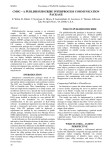
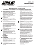
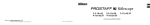
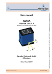
CMA Operating Manual: Canon Mask Aligner Introduction Use the Canon PLA-501F Mask Aligner (See Fig. 1: Right View) whenever you have a process flow that requires more than one mask on a wafer. If it is critical to align these masks with each other, you must use this tool. The Northern California Nanotechnology Center has two Aligners, both are rigged for four inch wafers. Safety Highlights: 1. If you haven't used the tool in a long time and have doubts about its operation, either ask a superuser to reacquaint you with it or work together with another knowledgeable user. 2. If you have any problems contact: Dan Haskell, 1125 Kemper Hall Corey Wolin, 1125 Kemper Hall Lab Manager Pre-operational Checklist Before you enter the cleanroom: 1. Have you arranged training from the superuser or lab manager on the Aligner? 2. See the manual "Introduction to the Northern California Nanotechnology Center" for general reminders about cleanroom practice. If you have questions about where things are stored or hung, ask the lab manager or a superuser. 3. Do you have your tweezers? First setup after entering the cleanroom: 1. Mark your use of this tool in the Aligner log book. Note any problems encountered by recent users. 2. Check to see if the mercury lamp is on. During the quarter it's best if the lamp remains on all the time. Turn on the mercury lamp thirty minutes to two hours before using the Aligner. a. Check to see that the Main Panel POWER is OFF. (Fig. 4: Main Panel). See Fig. 2: Top View to locate the Main Panel. b. Turn ON the POWER switch (Fig. 6: Mercury Lamp Power Supply). The mercury lamp power supply is on the floor by the right front table leg. c. Press the START switch (Fig. 6). d. DO NOT change the CURRENT ADJUSTMENT setting (Fig. 6). If you think it needs adjustment, talk with the lab technician. Setup after the mercury lamp has warmed up: 1. Turn on the house vacuum pump. 2. Check the pressure gauges (Fig. 2) to see if the nitrogen is on. If not, turn on the nitrogen. Generally, the nitrogen should always be on. 3. Turn ON the Aligner POWER (Fig. 4). 4. Turn ON the ILLUMINATOR. (Fig. 4). 5. Set the Main Panel switches (Fig. 4) as follows: CONTACT/PROXIMITY: CONTACT CONTACT: SOFT WAFER FEED: AUTO. 6. If the MANU lamp is not lit, press the MANU button (Fig. 4). 7. Set the LIGHT INTEGRA thumb wheel (Fig.4) between 45- 60. Exposure time for these settings is roughly 4.5-6 seconds. You may need to experiment to find the optimum setting for your process. 8. Adjust the eyepieces: a. Twist left and right FOCUS ADJUSTMENT knobs (Figs. 1-3) to obtain the desired field illumination. b. Set lens separation for correct binocular viewing: o i. Read the eyepiece separation value from between the eyepiece lenses. o ii. Set the dial on the barrel of each eyepiece to match the eyepiece separation value. Operating Instructions 1. Load and align the photomask. a. Unlock the saddle by pulling the Saddle Release Lever (Fig. 2). Swing the saddle to the right while holding the saddle handle (see Figs. 1; and 3: Left View). b. Fit the photomask, chrome or emulsion side down, onto the photomask holder. Rest it against the three guide pins (two on the back, one on the left). c. Press the MASK LOAD switch on the main panel (Fig. 4). d. Turn the photomask with the Photomask Rotational Adjustment knob (Fig. 1) so that the front edge of the mask is roughly parallel to the front of the Aligner. e. Swing the saddle back to its original position. f. Use the Objective Spacing knobs (Figs. 1-3) to find vertical scribe lines, i.e., the edge of the die. The Objective Spacing knobs move the left and right objective lenses horizontally. g. Turn the Photomask Rotational Adjustment knob until the same patterns are seen in both fields of view. Horizontal mask patterns should be parallel to a line through the centers of both the right and left objective lenses. h. Use the Scanning Grip (Fig. 3) to find the alignment structures (usually crosses). You will use these structures later to align wafers to the mask. 2. Load the wafer. For manual loading, see Subroutine 2: Manual Wafer Load below. For automatic loading, follow these steps: a. Place the wafer carriers with the H-bar side down (see Fig. 7: Wafer Carrier) on the Wafer Supply and Take-up Stages (Fig. 2). Place unexposed wafers, photoresist side up, in the supply carrier you placed on the Supply Stage. The take-up carrier should be empty. b. Press the START switch (Fig. 5: Front Panel). See (Fig. 2) to locate the Front Panel. The wafer moves to the pre-alignment station where it is automatically pre-aligned. Next, an auto hand swings the wafer from the pre-alignment station to the wafer chuck and sets the required alignment gap. Then the ALIGN lamp flashes (Fig. 5). 3. Make a coarse wafer alignment. a. Again unlock the saddle by pulling the Saddle Release Lever forward (Fig. 2). Swing the saddle to the right while holding the saddle handle. b. With the naked eye make a rough alignment with the XY alignment grip (Fig. 2). Press in the black button just above the grip to do a coarse alignment. Release the button for a fine alignment. On the front panel, press the top button on the Fine/Coarse Wafer Angle Control Selector (Fig. 5). This button determines the speed of rotational alignment. c. Now make a rough aligment with the Wafer Angle Control (Fig. 5). On the front panel, press the top button on the Fine/Coarse Wafer Angle Control Selector (Fig. 5). This button determines the speed of rotational alignment. d. Return the saddle to its original position. 4. Align the wafer to the mask. a. If this is the first mask level for a batch of wafers, see Subroutine 1: First Mask Exposure below. b. If necessary, focus the left view field with the Focus Adjust Knob for both fields of view (Fig. 2). Then focus the right view field with the right Focus Adjust knob (Figs. 2 &3). c. If the mask alignment structures are not in both the left and right fields of view, repeat steps 1 (f) - (h) above. d. Find an alignment structure on the wafer in the left field of view using the XY alignment grip (Figs. 1 & 2). Make a coarse alignment. e. Find a second alignment structure in the right field of view using the Wafer Angle Control (Fig. 5). Make a coarse alignment. f. Align the wafer alignment structure in the left view field to the mask alignment structure using the XY alignment grip. Make first a coarse alignment and then a fine one. Release the button on the grip to do fine alignments. g. Align the wafer alignment structure in the right field of view to the mask alignment structure using the Wafer Angle Control (Fig. 5). Make first a coarse alignment and then a fine one. Press the appropriate button on the Fine/Coarse Wafer Angle Control Selector to switch from coarse to fine alignment (Fig. 5). This rotation will move the wafer alignment structure in both the left and right fields of vision. Therefore: h. Go back and repeat steps 4 (f) - (g) making fine alignments until the alignment structures in both fields of vision are aligned. i. Press the ALIGN switch (Fig. 5). The EXPO lamp will start flashing. (Fig. 5). The wafer now rises and makes contact with the mask. DO NOT move either the wafer or the mask after they have made contact. j. Check to see if the wafer and the mask are still correctly aligned. If the wafer has lost its proper alignment, press the ALIGN switch and repeat steps 4 (d) - (i). 5. Expose wafer. a. Attached to the frame of the scanning grip (Fig. 3) is a small horizontal grid and vertical pointer. Use the scanning grip to move the pointer to the approximate center of the grid. This centers the exposure lens over the wafer. b. Press the EXPO switch (Fig. 5). The EXPO lamp lights, the ALIGN lamp goes out, and the wafer is exposed. After the wafer is exposed it is automatically ejected to the Take-up Stage and the next wafer is placed on the chuck ready for alignment. Subroutine 1: First Mask Exposure Because the first mask layer does not need coordination with previously aligned layers, one is free to expose it without alignment. Indeed, the Canon Mask Aligner can automatically expose an unpatterned batch of wafers without user assistance. 1. For the first wafer of a batch of unpatterned wafers, follow the operating procedure through step 3 (d). 2. Press the ALIGN switch. 3. Press the EXPO switch on the front panel (Fig. 5) and then immediately press the 1ST MASK switch on the main panel (Fig. 4). The Aligner will automatically pre-align, gap set, expose, and eject each succeeding wafer. Until the batch is finished, DO NOT touch the Wafer XY Alignment Adjustment knob (Figs. 1 & 2), the Wafer Angle Control (Fig. 5), or the Photomask Rotational Adjustment knob (Fig. 1). Subroutine 2: Manual Wafer Load Normally one loads the wafer so that the primary flat faces the rear of the aligner. By using manual load the flat may be oriented in any direction you desire. For a manual load, substitute the following procedure for the Operating Instructions step 2 above. 1. Set the Wafer Feed switch on the main panel to MANU (Fig. 4). 2. Using tweezers, place the wafer in the pre-alignment station oriented as you wish. On your left, find the prealignment station. It is under the auto hand at the end of the tracks leading from the Wafer Supply Stage. Allow for the rotation of the auto hand. The auto hand will rotate the wafer 130° clockwise when it loads the wafer. Log Off 1. Leave the mercury lamp on if you plan to use this tool again within a week. In general, leave the lamp on throughout each quarter. This saves wear and tear on the bulb. 2. Remove your aligned wafers. 3. You're finished! Troubleshooting 1. Check the logbook for any problems on prior runs. 2. If the auto arm fails to pick up the wafer from the pre-alignment stage, check whether you have turned on the vacuum pump. If the vacuum is on, check your wafer to see if it is uneven. If the wafer is not problematic, the suction cups on the auto arm may be the problem. Contact the lab technician for repairs. 3. For other problems, talk with the lab technician or check the manufacturer's service manual, section II. Find this manual in room 2136 Kemper Hall, filed under "Canon." Figures