1
Table of Contents
Job Specification Sheet....................................................................................................................................................3
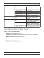
General Commercial Pre-Installation Check List..............................................................................................................4
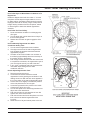
3200 Timer Setting Procedure..........................................................................................................................................5
3210 Timer Settings.........................................................................................................................................................6
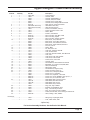
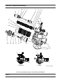
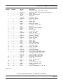
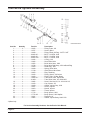
3200 & 3210 Timer Series................................................................................................................................................7
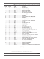
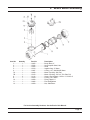
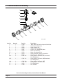
3200 Timer Assembly.....................................................................................................................................................10
3210 Timer Assembly.....................................................................................................................................................12
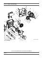
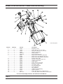
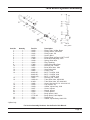
Upper Environmental Powerhead Assembly..................................................................................................................14
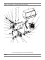
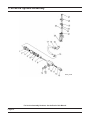
Lower Environmental Powerhead Assembly..................................................................................................................16
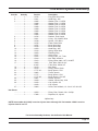
Lower Designer Powerhead Assembly...........................................................................................................................17
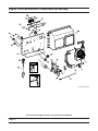
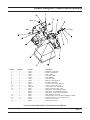
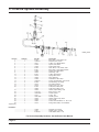
Upper Designer Powerhead Assembly...........................................................................................................................18
Control Valve Assembly..................................................................................................................................................20
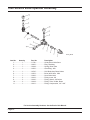
1600 Brine System Assembly.........................................................................................................................................22
1650 Brine System Assembly.........................................................................................................................................23
1700 Brine System Assembly.........................................................................................................................................24
1710 Brine System Assembly.........................................................................................................................................26
2” Brass Meter Assembly...............................................................................................................................................27
2” Plastic Meter Assembly..............................................................................................................................................28
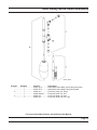
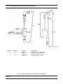
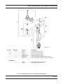
2300 Safety Brine Valve Assembly.................................................................................................................................29
2310 Safety Brine Valve Assembly.................................................................................................................................30
2350 Safety Brine Valve Assembly.................................................................................................................................31
1600 Service Valve Operator Assembly.........................................................................................................................32
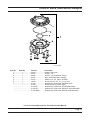
Control Valve Side Mount Adapter..................................................................................................................................33
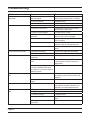
Troubleshooting..............................................................................................................................................................34
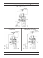
Water Conditioner Flow Diagrams - Downflow...............................................................................................................36
Water Conditioner Flow Diagrams - Upflow...................................................................................................................38
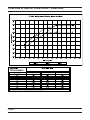
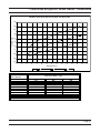
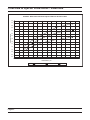
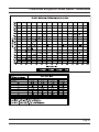
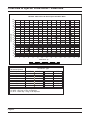
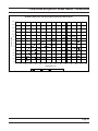
Flow Data & Injector Draw Rates - Downflow................................................................................................................40
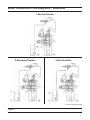
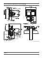
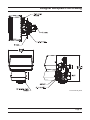
Environmental Backplate Line Drawing..........................................................................................................................46
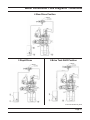
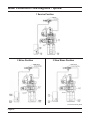
Designer Backplate Line Drawing..................................................................................................................................47
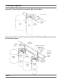
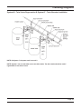
Plumbing Diagrams........................................................................................................................................................48
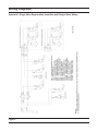
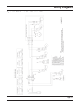
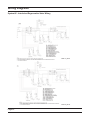
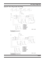
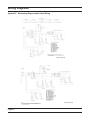
Wiring Diagrams.............................................................................................................................................................50
1600/1700 System Nozzle & Throat Chart.....................................................................................................................56
Service Assemblies........................................................................................................................................................57
IMPORTANT PLEASE READ:
•
The information, specifications and illustrations in this manual are based on the latest information available at the time of
printing. The manufacturer reserves the right to make changes at any time without notice.
•
This manual is intended as a guide for service of the valve only. System installation requires information from a number of
suppliers not known at the time of manufacture. This product should be installed by a plumbing professional.
•
This unit is designed to be installed on potable water systems only.
•
This product must be installed in compliance with all state and municipal plumbing and electrical codes. Permits may be
required at the time of installation.
•
If daytime operating pressure exceeds 80 psi, nighttime pressures may exceed pressure limits. A pressure reducing valve must
be installed.
•
Do not install the unit where temperatures may drop below 32°F (0°C) or above 125°F (52°C).
•
Do not place the unit in direct sunlight. Black units will absorb radiant heat increasing internal temperatures.
•
Do not strike the valve or any of the components.
•
Warranty of this product extends to manufacturing defects of the vessel and controller, not the membrane. Misapplication of this
product may result in failure to properly condition water, or damage to product.
•
A prefilter should be used on installations in which free solids are present.
•
In some applications local municipalities treat water with Chloramines. High Chloramine levels may damage valve components.
•
Correct and constant voltage must be supplied to the control valve to maintain proper function.