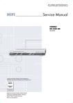
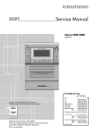
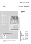
1
Service Manual
HiFi
VERTIGA
UMS 4600 DEC
GLR1200
H
C
U
A
R
EB LY
G
N
N
E
O
N
R
SE
E
U
T
L
IN
A
R
N
R
FÜ
E
T
R
NU OR IN
F
Zusätzlich erforderliche Unterlagen für den Komplettservice
Additionally required Service Documents for the Complete Service
Service
Manual
Sicherheit
Safety
Materialnr./Part No.
720108000001
Materialnummer/Part Number 720107740000
Änderungen vorbehalten/Subject to alteration
TCC 0206 HH • Prepared in Germany
http://www.grundig.com
GRUNDIG Service
VERTIGA UMS 4600 DEC
Es gelten die Vorschriften und Sicherheitshinweise gemäß dem Service Manual "Sicherheit",
Materialnummer 720108000001, sowie zusätzlich die eventuell abweichenden, landesspezifischen Vorschriften!
The regulations and safety instructions shall be
valid as provided by the "Safety" Service Manual,
part number 720108000001, as well as the respective national deviations!
Inhaltsverzeichnis
Table of Contents
Seite
Page
Allgemeiner Teil ............................... 1-2 … 1-12
General Section ................................ 1-2 … 1-12
Messgeräte / Messmittel .............................................................. 1-2
Allgemeine Hinweise .................................................................... 1-2
Technische Daten ........................................................................ 1-3
Servicehinweise ........................................................................... 1-3
Bedienhinweise ............................................................................ 1-4
Ausbauhinweise ......................................................................... 1-12
Measuring Instruments / Equipment ............................................ 1-2
General Notes .............................................................................. 1-2
Technical Data ............................................................................. 1-3
Service Hints ................................................................................ 1-3
Operating Hints ............................................................................ 1-8
Disassembly Hints ..................................................................... 1-12
Abgleichvorschriften .................................... 2-1
Adjustment Procedures ................................ 2-1
Platinenabbildungen
und Schaltpläne ............................... 3-1 … 3-14
Layout of PCBs
and Circuit Diagrams ....................... 3-1 … 3-14
Blockschaltplan ............................................................................ 3-1
Verdrahtungsplan ......................................................................... 3-2
Netzteil ......................................................................................... 3-3
Verstärker .................................................................................... 3-4
Hauptplatte ................................................................................... 3-5
CD-Teil ......................................................................................... 3-8
USB-Teil ..................................................................................... 3-11
Display-Platte/Bedienteil ............................................................ 3-13
Block Diagram .............................................................................. 3-1
Wiring Diagram ............................................................................ 3-2
Power Supply ............................................................................... 3-3
Amplifier ....................................................................................... 3-4
Main PCB ..................................................................................... 3-5
CD Section ................................................................................... 3-8
USB Section ............................................................................... 3-11
Display Board/Keyboard ............................................................ 3-13
Explosionszeichnung und
Ersatzteilliste ...................................... 4-1 … 4-2
Exploded View and
Spare Parts List .................................. 4-1 … 4-2
Explosionszeichnung ................................................................... 4-1
Ersatzteilliste ................................................................................ 4-2
Exploded View ............................................................................. 4-1
Spare Parts List ........................................................................... 4-2
Allgemeiner Teil
General Section
Messgeräte / Messmittel
Measuring Instruments / Equipment
Mess-Sender
Oszilloskop
Trenntrafo
Signal generator
Oscilloscope
Insulating transformer
Wobbelsender
Digitalvoltmeter
Klirrfaktormessgerät
Sweep generator
Digital voltmeter
Distortion meter
Allgemeine Hinweise
General Notes
Vor dem Öffnen des Gehäuses zuerst den Netzstecker ziehen!
Before opening the cabinet disconnect the mains plug!
Achtung: ESD-Vorschriften beachten
Attention: Observe the ESD safety regulations
Leitungsverlegung
Bevor Sie die Leitungen und insbesondere die Masseleitungen lösen,
muss die Leitungsverlegung zu den einzelnen Baugruppen beachtet
werden.
Nach erfolgter Reparatur ist es notwendig, die Leitungsführung wieder
in den werkseitigen Zustand zu versetzen um evtl. spätere Ausfälle
oder Störungen zu vermeiden.
Wiring
Before disconnecting any leads and especially the earth connecting
leads observe the way they are routed to the individual assemblies like
the chassis, mains switch panel, keyboard control panel, picture tube
panel, deflection unit, loudspeaker and so on.
On completion of the repairs the leads must be laid out as originally
fitted at the factory to avoid later failures or disturbances.
Durchführen von Messungen
Bei Messungen mit dem Oszilloskop an Halbleitern sollten Sie nur
Tastköpfe mit 10:1 - Teiler verwenden. Außerdem ist zu beachten,
dass nach vorheriger Messung mit AC-Kopplung der Koppelkondensator des Oszilloskops aufgeladen sein kann. Durch die Entladung
über das Messobjekt können Bauteile beschädigt werden.
Carrying out Measurements
When making measurements on semi-conductors with an oscilloscope, ensure that the test probe is set to 10:1 dividing factor. If the
previous measurement was made on AC input, please note that the
coupling capacitor in the oscilloscope will be charged. Discharge via
the item being checked can damage the components.
Messwerte
Bei den in den Schaltplänen angegebenen Messwerten handelt es
sich um Näherungswerte!
Measured Values
The measured values given in the circuit diagrams are approximates!
1-2
GRUNDIG Service
VERTIGA UMS 4600 DEC
Technische Daten
Technical Data
System
Spannungsversorgung:
Betriebsspannung ................................................................... 230V~
Netzfrequenz ........................................................................ 50/60Hz
Max. Leistungsaufnahme ........................................................... 28W
Leistungsaufnahme in Stand-by ................................................ ≤5W
System
Power supply:
Operating voltage ................................................................... 230V~
Mains frequency ................................................................... 50/60Hz
Max. power consumption .......................................................... 28W
Power consumption in stand-by ................................................. ≤5W
Verstärkerteil
Ausgangsleistung:
Sinusleistung .......................................................................... 2 x 5W
Musikleistung ......................................................................... 2 x 8W
Amplifier unit
Output:
Sine wave power .................................................................... 2 x 5W
Music signal power ................................................................ 2 x 8W
Empfangsteil
Empfangsbereich:
FM .......................................................................... 87,5 ...108,0MHz
MW ........................................................................... 522 ... 1620kHz
Receiver unit
Reception range:
FM .......................................................................... 87.5 ...108.0MHz
MW ........................................................................... 522 ... 1620kHz
CD Teil
Frequenzgang .......................................................... 100Hz ... 15kHz
Geräuschspannungsabstand (bewertet) ................................. ≥60dB
CD unit
Frequency response ................................................ 100Hz ... 15kHz
Noise-voltage ratio (wtd.) ........................................................ ≥60dB
MP3-Features
Alben und Files ................... Max. 200 Alben, max. 500 Files pro CD
File System/File Management ............ ISO 9660 Level 1 kompatibel
MP3 features
Albums and files: ............... Max. 200 albums, max. 500 files per CD
File system/file management .............. ISO 9660 Level 1 compatible
Abmessungen
Abmessungen Gerät B x H x T .......................... 170 x 172 x 250mm
Abmessungen Lautsprecher B x H x T .............. 128 x 255 x 148mm
Dimensions
Device dimensions W x H x D ........................... 170 x 172 x 250 mm
Loudspeaker dimensions W x H x D .................. 128 x 255 x 148mm
Gewicht
Gewicht Gerät ........................................................................... 2,4kg
Gewicht pro Lautsprecher ........................................................ 0,8 kg
Weight
Device weight ............................................................................ 2.4kg
Weight per loudspeaker ............................................................ 0.8kg
Servicehinweise
Service Hints
Achtung: ESD-Vorschriften beachten
Attention: Observe the ESD safety regulations
Vor Öffnen des Gehäuses Netzstecker ziehen.
Disconnect the mains plug before opening the set.
CD-Laufwerk
Bei Ausbau der Lasereinheit oder der Servo-Leiterplatte muß vor
Abziehen der Steckverbindung eine Schutzlötstelle auf der Leiterplatte der Lasereinheit angebracht werden, um eine Zerstörung der
Laserdioden durch statische Aufladung zu vermeiden.
CD Mechanism
When removing the Laser pick-up or the Servo PCB, the Laser pickup PCB must be provided with a protective soldered joint before
unplugging the connectors to avoid damage to the Laser diodes by
static charges.
Beim Einbau einer neuen Lasereinheit (CD-Laufwerk) muß nach
Einstecken der Steckverbinder die werkseitig angebrachte
Schutzlötstelle entfernt werden!
When inserting the new Laser pick-up (CD drive mechanism) the
soldered joint fitted at the factory must be removed after the
connectors are plugged in.
Schutzlötstelle
Protective soldered joint
1-3
GRUNDIG Service
Bedienhinweise
Dieses Kapitel enthält Auszüge aus der Bedienungsanleitung. Weitergehende Informationen entnehmen Sie bitte der gerätespezifischen Bedienungsanleitung, deren Materialnummer Sie in der Ersatzteilliste finden.
1-4
VERTIGA UMS 4600 DEC
GRUNDIG Service
1-5
VERTIGA UMS 4600 DEC
GRUNDIG Service
1-6
VERTIGA UMS 4600 DEC
GRUNDIG Service
1-7
VERTIGA UMS 4600 DEC
GRUNDIG Service
Operating Hints
This chapter contains excerpts from the operating instructions. For further particulars please refer to the appropriate user instructions the part number of which is indicated in the relevant spare parts list.
1-8
VERTIGA UMS 4600 DEC
GRUNDIG Service
1-9
VERTIGA UMS 4600 DEC
GRUNDIG Service
1 - 10
VERTIGA UMS 4600 DEC
GRUNDIG Service
1 - 11
VERTIGA UMS 4600 DEC
Schrauben B und C (4 davon unter A)
B
Screws B and C (4 below A)
A
GRUNDIG Service
Ausbauhinweise / Disassembly Hints
Gehäuse öffnen / Open the cabinet:
759541045600
1 - 12
C
VERTIGA UMS 4600 DEC
GRUNDIG Service
VERTIGA UMS 4600 DEC
Abgleichvorschriften
Tuner
Messgeräte: Mess-Sender, Digital-Voltmeter
Abgleich
Vorbereitung
Abgleichvorgang
1. MW-Oszillator
Digital-Voltmeter an Messpunkt TP1 (VT).
Bei 530kHz mit T101 auf 1,0V (+ 0,5V/- 0,2V) abgleichen.
2. AM-ZF
Mess-Sender über Loopantenne einkoppeln.
f = 450kHz; ohne Modulation
Digital-Voltmeter an Messpunkt TP2.
Mit T102 auf Maximum abgleichen.
3. MW-Eingangskreis
Mess-Sender über Loopantenne einkoppeln.
ohne Modulation
Digital-Voltmeter an Messpunkt TP2.
Wechselweise mit MW COIL (auf der Ferrit-Antenne) bei
603kHz und mit TC101 bei 1404kHz auf Maximum abgleichen.
Adjustment Procedures
Tuner
Test equipment: Signal Generator, Digital Voltmeter
Adjustment
Preparation
Adjustment Procedure
1. MW Oscillator
Digital Voltmeter to Testpoint TP1 (VT).
At 530kHz adjust T101 for 1.0V (+ 0.5V/- 0.2V).
2. AM IF
Couple Signal Generator via Loop Antenna.
f = 450kHz; no modulation
Digital Voltmeter to Testpoint TP2.
Adjust T102 for maximum.
3. MW Pre Stage
Couple Signal Generator via Loop Antenna.
no modulation
Digital Voltmeter to Testpoint TP2.
Adjust alternating with MW COIL (on the ferrite antenna)
at 603kHz and with TC101 at 1404kHz for maximum.
TC101
IC101
T101
IC103
TP2/PIN 19
IC104
T102
TP1/PIN 5
2-1
Blockschaltplan / Block Diagram
GRUNDIG Service
Schaltpläne und Platinenabbildungen / Circuit Diagrams and Layout of the PCBs
3-
VERTIGA UMS 4600 DEC
GRUNDIG Service
VERTIGA UMS 4600 DEC
Verdrahtungsplan / Wiring Diagram
Power
Supply
CD+MCU Board
Amplifier
Board
Main Board
Display Board
3-
GRUNDIG Service
VERTIGA UMS 4600 DEC
Netzteil / Power Supply
p. 3-4
3-
GRUNDIG Service
Verstärker / Amplifier
p. 3-3
p. 3-6
p. 3-6
3-
p. 3-6
VERTIGA UMS 4600 DEC
p. 3-6
GRUNDIG Service
VERTIGA UMS 4600 DEC
Hauptplatte / Main PCB
to W403
p. 3-8
to CN792
p. 3-9
3-
GRUNDIG Service
VERTIGA UMS 4600 DEC
Hauptplatte / Main PCB
to CN101
p. 3-8
to CN603
p. 3-4
to W791
p. 3-8
to CN405
p. 3-13
to CN302
p. 3-8
to CN604
p. 3-4
to CN413
p. 3-4
3-
to CN605
p. 3-4
GRUNDIG Service
VERTIGA UMS 4600 DEC
Hauptplatte / Main PCB
3-
GRUNDIG Service
VERTIGA UMS 4600 DEC
CD-Teil / CD Section
to CN105
p. 3-5
to CN107/p. 3-6
to CN101
p. 3-6
to CN102
p. 3-6
to CN403/p. 3-13
to CN201/202/p. 3-13
3-
GRUNDIG Service
VERTIGA UMS 4600 DEC
to CN103/p. 3-5
to CN402/p. 3-11
CD-Teil / CD Section
to CN404/p. 3-13
3-
GRUNDIG Service
VERTIGA UMS 4600 DEC
CD-Teil / CD Section
3 - 10
GRUNDIG Service
USB-Teil / USB Section
3 - 11
to W402
p. 3-9
VERTIGA UMS 4600 DEC
GRUNDIG Service
VERTIGA UMS 4600 DEC
USB-Teil / USB Section
3 - 12
GRUNDIG Service
VERTIGA UMS 4600 DEC
Display-Platte/Bedienteil / Display Board/Keyboard
p. 3-9
p. 3-6
p. 3-8
CN404/405/407/408/p. 3-8
3 - 13
GRUNDIG Service
VERTIGA UMS 4600 DEC
Display-Platte/Bedienteil / Display Board/Keyboard
3 - 14
Exploded View and Spare Parts List
GRUNDIG Service
Explosionszeichnung und Ersatzteilliste
VERTIGA UMS 4600 DEC
4-1
VERTIGA UMS 4600 DEC
Ersatzteilliste
Spare Parts List
NUR FÜR INTERNEN GEBRAUCH
FOR INTERNAL USE ONLY
VERTIGA UMS 4600 DEC
12 / 2005
MATERIAL-NR. / PART NO.: 720123225100
BESTELL-NR. / ORDER NO.: GLR1200
ERSETZT AUSGABE 11/2005
SUBSTITUTE EDITION 11/2005
POS. NR. ABB.
POS. NO. FIG.
4-2
0001.000
0002.000
0003.000
0017.000
0018.000
0019.000
0020.000
0024.000
0027.000
0028.000
0029.000
0034.000
0035.000
0036.000
0038.000
0040.000
0043.000
0044.000
0046.000
0048.000
0051.000
0063.000
0064.000
0066.000
0069.000
0071.000
0073.000
0074.000
0076.000
0083.000
0089.000
0090.000
0091.000
0092.000
0093.000
0095.000
S
S
S
HiFi
GRUNDIG Service
ǵ
MATERIAL-NR. ANZ.
PART NUMBER QTY.
BEZEICHNUNG
DESCRIPTION
d
©
GLR1200
VERTIGA UMS 4600 DEC GRAPHIT
TAUSCHGERAET
VERTIGA UMS 4600 DEC GRAPHIT
EXCHANGE SET
759541042200
759541042300
759541042400
759541042500
759541042600
759541042700
759541042800
759541042900
759541043000
759541043100
759541043200
759541043300
759541044900
759541043400
759541043500
759541043600
759541043700
759541043800
759541043900
759541043800
759541044000
759541044100
759541044200
759541044300
759541045000
759541044400
759541044500
759541044600
759541044700
759541044800
759541045600
759541045500
759541045400
759541045700
759541045800
720117137300
FRONT KLAPPE
GEHAEUSEVORDERTEIL UNTEN
USB KNOEPFE
KNOPF FUNKTION
LICHTLEITER
GEHAEUSEVORDERTEIL
USB KARTENMODUL
LCD/BEDIENMODUL
KNOPF NETZ
BEDIENKNOEPFE CD
LINSE KNOPF NETZ
DISPLAY
HAUPTMODUL
KNOPF VOLUMEN
REFLEKTOR
LINSE KNOPF VOLUMEN
TRANSFORMATOR
GUMMI FUSS
GEH.-RUECKTEIL
GUMMI FUSS
GLEICHRICHTERMODUL
VERSTAERKERMODUL
SCHALTER LS-201V-002
CD-TRAEGER
CD-MODUL
RAD MOTOR
ZAHNRAD
TRAEGER ZAHNRAD
DECKEL CD
CD-MECHANIK
FOLIE AUX IN
LAUTSPRECHERBOX OHNE GITTER
ABDECKUNG LAUTSPRECHERBOX
RIEMEN
NETZKABEL
FERNBEDIENUNG
FRONT DOOR
FRONT CABINET DOWN
USB KNOB
KNOB FUNCTION
LUMINAT
FRONT CABINET
USB CARD BOARD
LCD/CONTROLBOARD
KNOB POWER
CONTROL KNOBS CD
LENS KNOB POWER
DISPLAY
MAINBOARD
KNOB VOLUME
REFLECTOR
LENS KNOB VOLUME
TRANSFORMER
RUBBER FOOT
BACK CABINET
RUBBER FOOT
RECTIFIERBOARD
AMPLIFIER BOARD
SWITCH LS-201V-002
CD-TRAY
CD-BOARD
WHEEL MOTOR
GEAR
GEAR BRACKET
CD DOOR
CD-MECHANISM
FOIL AUX IN
LOUDSPEAKERBOX WITHOUT GRILLE
COVER LOUDSPEAKERBOX
BELT
POWER CORD
REMOTE CONTROL
720114058500
720114058600
720107740000
BEDIENUNGSANLEITUNG D/GB/F/I/P/E
BEDIENUNGSANLEITUNG NL/PL/DK/S/FIN/TR
SERVICE MANUAL D/GB
INSTRUCTION MANUAL D/GB/F/I/P/E
INSTRUCTION MANUAL NL/PL/DK/S/FIN/TR
SERVICE MANUAL D/GB
MATERIAL-NR. BEZEICHNUNG
PART NUMBER DESCRIPTION
LED 1
LED 2
LED 3
LED 4
759541045100
759541045200
759541045300
759541045300
POS. NR.
POS. NO.
MATERIAL-NR. BEZEICHNUNG
PART NUMBER DESCRIPTION
LED WEISS
LED ULTRABLAU
LED BLAU
LED BLAU
Es gelten die Vorschriften und Sicherheitshinweise
gemäß dem Service Manual "Sicherheit", Mat.-Nummer 720108000001, sowie zusätzlich die eventuell abweichenden, landesspezifischen Vorschriften!
!
(!)
The regulations and safety instructions shall be valid
as provided by the "Safety" Service Manual, part
number 720108000001, as well as the respective
national deviations.
ÄNDERUNGEN VORBEHALTEN / SUBJECT TO ALTERATION
VERTIGA UMS 4600 DEC
POS. NR.
POS. NO.