1
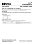
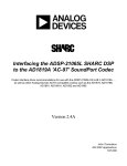
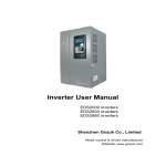
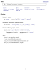
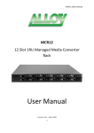
Engineer-To-Engineer Note
EE-74
Technical Notes on using Analog Devices’ DSP components and development tools
Phone: (800) ANALOG-D, FAX: (781) 461-3010, EMAIL: [email protected], FTP: ftp.analog.com, WEB: www.analog.com/dsp
Copyright 1999, Analog Devices, Inc. All rights reserved. Analog Devices assumes no responsibility for customer product design or the use or application of customers’ products
or for any infringements of patents or rights of others which may result from Analog Devices assistance. All trademarks and logos are property of their respective holders.
Information furnished by Analog Devices Applications and Development Tools Engineers is believed to be accurate and reliable, however no responsibility is assumed by Analog
Devices regarding the technical accuracy of the content provided in all Analog Devices’ Engineer-to-Engineer Notes.
Analog Devices Serial Port Development and Troubleshooting Guide
Compiled by the Analog Devices DSP Applications group
Introduction
The purpose of this document is to assist engineers in the design and debugging of serial port communications in
systems using Analog Devices’ DSPs. First, it will cover general system design strategies to help ensure low
noise levels and valid signals throughout the system. Next, it will focus on common serial port problems and
their respective solutions. This section is processor nonspecific. The following section deals with processor
specific issues, these being the ADSP21xx family and the ADSP2106x family of DSPs. Finally, there is a
section containing example serial-port initialization code for both families of DSPs.
General ADSP-21xx / 2106x DSP SPORT Design Issues
(Note: because the serial ports on both the ADSP21xx and ADSP2106x families
of DSPs are very similar in architecture and functionality, the issues presented in
the section apply to both)
Perhaps one of the largest cause of serial port problems is poor board design. The serial ports are essentially
edge-triggered state machines - this means that every time a valid edge occurs on a serial clock line, the state
machine is stimulated. A valid edge occurs when the voltage level on a serial port line passes across
approximately 2.5 Volts in 5 Volt parts and 1.3 Volts in 3.3V parts - we will refer to this as the critical
voltage. If the serial clock is set to ‘positive edge’ polarity (configurable in serial port control register), a valid
edge occurs when the voltage on the serial clock line passes from below the critical voltage to above the critical
voltage. On the other hand, if the serial clock is set to ‘falling edge’ polarity, a valid edge occurs when the
voltage passes from above the critical voltage to below the critical voltage.
a
Positive Edge Polarity
vali
d
Negative Edge Polarity
Vcc
Critical
point
Vcc
vali
d
Critical
point
Vdd
Vdd
Figure 1 : Positive and Negative Edge Polarity
There are many design related problems that can cause noisy serial clock lines which can potentially cross the
critical voltage multiple times per one clock pulse. The example below presents two variations of the same
serial clock signal - one has a large signal reflection which causes each period of the serial clock to cross the
critical point multiple times. This will cause the state machine within the serial port to sample the serial data lines
twice per clock period causing the serial data to become corrupted. The other signal is properly compensated
so no reflections occur and the data is sampled once per period.
This signal does not contain reflections
This signal contains reflections
Figure 2: Signals with reflections
The following sections present specific design strategies to avoid problems like this one.
Decoupling the DSP’s Vcc and GND Pins
The DSP should have a .1µF capacitor connected between each of its Vcc and Gnd (Vdd) pins. This helps
keep the power supply to the DSP clean of voltage spikes and dips on the Vcc and Gnd lines. Large spikes
and dips in the Vcc and Gnd lines can cause the processor to jump into an unknown state potentially causing the
processor to crash. These capacitors should be placed as close as possible to the actual Vcc and Gnd pins of
the chip for maximum effectiveness.
Hardware Construction (PCB vs. Wirewrap)
EN-74
Page 2
Technical Notes on using Analog Devices’ DSP components and development tools
Phone: (800) ANALOG-D, FAX: (781) 461-3010, FTP: ftp.analog.com, EMAIL: dsp.support @analog.com
Signal Trace Length
Serial lines greater than about 3” will require some sort of reflection compensation. Details about this are
covered in the solutions section.
Common Serial Port Problems
This section is a troubleshooting guide. Each problem listed below contains a description of why it exists and
some techniques to isolate a specific cause. Once the cause is determined, a reference is provided for the
solutions table where conveniently enough, solutions can be found.
DSP is Receiving and/or Transmitting Corrupt Data
First ensure that the device communicating with the DSP is operating correctly. If the DSP is receiving corrupt
data, it may be because the device it is communicating with is transmitting corrupt data. If it is, make sure that
the signals that it is generating are clean, meet required timing specs and have good levels.
Below is an example of communications system where data is being corrupted:
Serial Clock
DSP 1
Serial Data
DSP 2
Frame Sync
Shifted Data:
When serial data received by DSP 2 is a shifted version of the data transmitted by DSP 1, this usually means
there is a data synchronization problem. This is often common when transmitting unframed data and can be
caused by a noisy serial clock or system noise. Below are a few examples of 8-bit data words which have been
shifted during the transmission from DSP 1 to DSP 2.
Data Sent from DSP 1:
10101010
11110000
00001111
Data Received by DSP 2:
01010101
01111000
00011111
See items:
EN-74
Page 3
Technical Notes on using Analog Devices’ DSP components and development tools
Phone: (800) ANALOG-D, FAX: (781) 461-3010, FTP: ftp.analog.com, EMAIL: dsp.support @analog.com
Incorrect Bits:
When serial data received by DSP 2 contains corrupted bits, there is usually a system noise problem. Below
are a few examples where 8-bit data words transmitted from DSP 1 to DSP 2 have become corrupted.
Data Sent from DSP 1:
10101010
11110000
00001111
Data Received by DSP 2:
10101110
10110010
01001111
No activity on serial port lines
When the serials ports are not enabled, the serial port signals are tristated.
Invalid line levels on serial port lines
Invalid line levels will occur when two devices are trying to drive the serial port. If one part is driving a serial
port line high and another is driving it low at the same time the resulting voltage on that line while be somewhere
between Vcc and Gnd. This can also damage one of the
Noise on serial port lines
Solutions Table
Proper termination of long SPORT traces
SPORT_Tech_Note.pd
f
The serial port on the DSP is very sensitive to any external noise in the system. This includes noise due to
reflections on the lines, signal degradation due to long trace lengths, and signal interference. Any trace that is
equal to or longer than 3--4 inches has to be treated as a transmission line at the high frequencies that the
SPORT generally operates at, and must be properly terminated to reduce noise and glitches on the lines. Failure
to do so may result in the SPORT locking up, or the SPORT transmitting or receiving incorrect data. In addition
EN-74
Page 4
Technical Notes on using Analog Devices’ DSP components and development tools
Phone: (800) ANALOG-D, FAX: (781) 461-3010, FTP: ftp.analog.com, EMAIL: dsp.support @analog.com
to good board layout and design considerations (refer High Speed Digital design book), a popular method to
reduce noise is to provide series termination resistors on the SPORT control lines, as close to the DSP
generating the signals as possible(preferably right next to the DSP).The value of the resistor typically ranges
between 20-100 ohms, but an exact value depends on the trace lengths and the characteristic impedance of the
line. Values can be determined by using an equation described in the book “High-Speed Digital Design-A
Handbook of Black Magic” by Howard W. Johnson and Martin Graham, and published by Prentice-Hall.
If the total electrical delay of the signal net in questions is greater than six times the rise or fall time of the source,
you should terminate the signal. Rough calculations of the total line length delay of the net should be calculated
with 0.180ns per inch and 2 pF per inch.
Example 1:
A driver is connected to 6 loads, each load is 8pf, the connection is a star connection, where the longest path
from the driver is 15 inches, the output impedance of the driver is 10 ohms, and the rise / fall time of the driving
signal is 2.0 ns max.
The max. rise and fall times of the Driving Signal is 2 ns.
The Total Signal trace delay is (15 * .180 ns) this is 2.7 ns.
The Total RC load delay is ((8 pF * 6) + (15 * 2 pF) * 10 ohms = 0.780 ns
Then the ratio of signal delay to rise time is signal delay / rise time equals 3.48 ns / 2.0 ns = 3.48 The ratio is
less than 6, so this signal should be OK, and Terminations would not be required.
Example 2:
A driver is connected to 6 loads, each load is 8pf, the connection is a star connection, where the longest path
from the driver is 30 inches, the output impedance of the driver is 15 ohms, and the rise / fall time of the driving
signal is 1.0 ns max.
The max. rise and fall times of the Driving Signal is 1 ns.
The Total Signal trace delay is (24 * .180 ns) this is 5.4 ns.
The Total RC load delay is ((8 pF * 6) + (30 * 2 pF) * 10 ohms = 1.00 ns
Then the ratio of signal delay to rise time is signal delay / rise time equals 6.4 ns / 1.0 ns = 6.4 The ratio is
greater than 6, this signal would cause reflection problems, and terminations should be used.
For a series termination: The termination value should be the PWB characteristic impedance minus the driver
output impedance. Example: Assuming a PWB Z of 50 ohms, and Driver Z of 10 ohms, then the series
termination located as close to the driver as possible would be 40 ohms.
EN-74
Page 5
Technical Notes on using Analog Devices’ DSP components and development tools
Phone: (800) ANALOG-D, FAX: (781) 461-3010, FTP: ftp.analog.com, EMAIL: dsp.support @analog.com
For a end termination (parallel split termination): The parallel equivalent termination value should be the PWB
characteristic impedance. Example: Assuming a PWB Z of 50 ohms, then the parallel equivalent split termination
values located as close to the end of the line as possible would be 50 ohms. You should not exceed IOH Max
and IOL Max of the Driver. After establishing the 2 resistor values for the termination (for most CMOS logic the
ratio should be the ratio of IOH and IOL), calculate the current through the two resistors based on the VOH
and VOL, if the current in either case exceeds IOH Max or IOL Max, you should not use a end termination
arrangement.
Processor Specific Issues
21xx
The questions and answers provided in this Tech-note are based on commonly asked questions from
customers, or information that is not documented extensively in the ADSP-2100 Family User’s manual, and is
intended to supplement the information provided therein.
The serial ports have the capability of transmitting and receiving serial data in the form of bits, with the MSB
first. Bits are clocked in at the rate of the serial port clock (which can either be internally generated by the DSP
as a fraction of the processor clock (CLKOUT), or externally generated by another device, and supplied to the
DSP). Bits are transmitted on the rising edge of an SCLK pulse, and received on the falling edge of an SCLK
pulse. The frame sync signal is used to signify the start of a serial data word or stream of serial words.
Continuous mode of operation of Serial Port
The ADSP-2100 Family User’s manual (third edition) describes the operation of the SPORTs in continuous
mode (for example, refer section 5.9 on timing examples on page 5-16). The serial port is said to operate in
the continuous mode while either transmitting or receiving, if a bit is shifted out or in with every SCLK pulse,
without a pause. This is not a special mode of operating the serial port, and hence there is no register or bit
associated with it. The value in the RFSDIV register determines the operation. For example, to set the serial
port up in this mode, with an internal RFS and alternate framing, set RFSDIV to be equal to the SLEN-1.
Internal generation of transmit and receive frame syncs with frame syncs NOT required
If a serial port is set for internal frame sync(transmit or receive) and the SPORT x Control register is configured
for “frame-sync-not-required”, (in other words, bits 11 and/or 13--the RFSR and the TFSR set to 0), the
serial port continues to generate a frame sync for every transmitted or received word. In other words,
operation of the SPORT is identical for either mode. The main difference is seen at the receiving end where if
the SPORT is set up for external frame sync, the DSP ignores the frame sync after the initial pulse.
EN-74
Page 6
Technical Notes on using Analog Devices’ DSP components and development tools
Phone: (800) ANALOG-D, FAX: (781) 461-3010, FTP: ftp.analog.com, EMAIL: dsp.support @analog.com
Disabling and Re-enabling SPORTs
At any time after a serial port is disabled, if it is necessary to re-enable it, it is recommended that the control
registers corresponding to the serial port be set up again before the SPORT is re-enabled.
If a serial port is set for internal frame sync and is then enabled, the first frame sync appears after RFSDIV serial
clock cycles.
When a serial port is set for internal frame sync and alternate mode, the smallest number that be written into the
RFSDIV register is the number of bits in each word. This is because the frame sync is active throughout the
length of the word.
Enabling SPORTS
It is critical that the RFSDIV register is set before enabling the sports. When the sports are enabled the register
will count to zero and you will get the receive frame sync 1-2 cycles later.
The total is n + (1 or 2)
1 cycle if in alternate frame mode
2 cycle if in normal frame mode
where n is the value of the receive count register
Use of gated serial clocks with the serial port
We strongly recommend the use of a continuous serial clock(internally generated by the DSP), or external for
the serial port. The reason for this is because of the latency involved, in that the DSP requires a few cycles to
synchronize the serial port after it receives the first serial clock pulse. However, if it is imperative for the specific
application to use a gated serial clock, it is important to ensure that the clock is not discontinued in the middle of
receiving or transmitting a word.
Disabling SPORT autobuffering temporarily
If a certain application requires the SPORT to be set up to receive a known number of words while using
autobuffering, and the user wishes to stop receiving words for some period of time before re-enabling it, two
options are available. The first is to disable autobuffering in the SPORTx receive interrupt service routine and
disable the SPORT. The SPORT continues to receive/transmit words until and unless autobuffering is disabled.
One must be aware of the latencies involved while re-enabling the SPORT at a future time.
The second option is to disable autobuffering and to simply mask off the SPORTx interrupt. This will cause the
SPORT to shift in words into the RXx register, but not interrupt the DSP. The following simple example
illustrates how this is done for the SPORT0 receiving data, on the ADSP-218x. A similar procedure can be
followed for SPORTx transmit interrupt.
SPORTx_RCV: AX0 = B#0xxxxxxxxxxxxxx0;
DM(Sportx_Autobuf_Ctrl) = AX0;
POP STS;
IMASK = B#xxxx0xxxxx;
EN-74
Page 7
Technical Notes on using Analog Devices’ DSP components and development tools
Phone: (800) ANALOG-D, FAX: (781) 461-3010, FTP: ftp.analog.com, EMAIL: dsp.support @analog.com
PUSH STS;
......
RTI;
It is necessary to manually pop and push the status register because the original IMASK was pushed onto the
stack before the interrupt is serviced.
To re-enable the SPORT at some future time, (it is possible to use an interrupt or a flag from the transmitter to
let the receiving DSP know it is ready to transmit again) it is only necessary to set the corresponding bit in the
IMASK register, in other words to H#xxxx1xxxxx, and re-enable the autobuffering. Once the receiving DSP
has done this, it can indicate to the transmitter that it is ready to receive the next set of words.
Startup Time
“When a serial port is enabled by a write to the System Control Register, it takes two SCLK cycles before it is
actually enabled. On the next (third) SCLK cycle, the serial port becomes active, looking for a frame sync.”
The SPORT was designed this way to synchronize the enable signal to the asynchronous serial clock. To the
clocked serial port, it appears that any cycle could be the start of a frameless data stream; there is a valid frame
signal every cycle. This causes the SPORT to skip the data on the first two or three cycles of SCLK if you are
not giving any cycles without the frame signal, since it ignores the frame signal until the SPORT becomes active.
This situation can happen to anyone using frameless modes with the clock only operating when data is being
sent.
The solution of sending a couple dummy bits will work fine if the SPORT is enabled long before the SCLK
starts, but could cause trouble if the enable bit is written at about the same time as the first SCLK cycle. An
alternate solution would be to have the frame signal de-asserted for 2 or more SCLK cycles, and than asserted
when the data starts. Some other processors have a special asynchronous start mode to better support the
"toggle the clock only when there is data" type of operation.
SHARC
Changing Multichannel TX and RX Channel Selects:
The MTCSx bits can be changed while the serial port is active as long as the current channel, STCTLx(CHNL),
does not correspond to timeslot of the changed bits. It is possible that the current channel can change to the next
channel after STCTLx(CHNL) is read. So writing to MTCSx must be avoided when the value of
STCTLx(CHNL) is equal to or one less than that of the timeslot for the changed bits in MTCSx. Changing
MRCSx can occur at any time, there is no problem even if the current channel corresponds to changed bit of
MRCSx.
Changing Multichannel TX and RX Companding Selects:
EN-74
Page 8
Technical Notes on using Analog Devices’ DSP components and development tools
Phone: (800) ANALOG-D, FAX: (781) 461-3010, FTP: ftp.analog.com, EMAIL: dsp.support @analog.com
The MTCCS and MRCCS bits are read during the transmission/reception of the last bit of the current channel
to about the time when the 2ndbit of next channel is transmitted. So these bits should not change in this window
of about 2 serial clock cycles. Since this window overlaps the current channel and the next channel, we can
follow the same rule which we do for MTCS bits. This means that we should avoid changing the MTCCS and
MRCCS bits when the changed bits corresponds to channel number. STCTL(CHAN) and STCTL(CHAN) +
1.
He was very concerned about a possible contention on the DTx pin of SPORT0 for multiple 218x dsp's in
multi-channel mode transmitting in adjacent channels with the frame delay = 0. He felt that there was a potential
15ns of overlap in transmitting for the last bit of one channel to the first bit in the next channel.
The particular specs of interest are Tscde and Tscdd.
In the schematics for the circuitry of the SPORT he found that there is a single signal that controls the
enable/disable of data transmission. The min for Tscde comes from the case where SPORT DTx was enabled
in the previous SCLK cycle and therefore no transition takes place. The max. spec for Tscdd comes from the
case where SPORT DTX was enabled in the previous SCLK cycle and therefore a transition to disable is
necessary.
From this it is apparent that since both 218x's will be transitioning at the overlap (one from enable to disable and
the other from enable to disable), each will experience very close to the same delay and therefore the overlap
will be very small and the contention will be negligible.
1. Does the SPORT need an input on TCLK, or does the transmitter use RCLK for transmitting in multichannel
mode? If it does use RCLK, what should we do with TCLK input? ANS: On same SPORT, the DT & DR
lines are connected together.
The TCLK input can be left floating.
2. What does the transmitter send after it completes sending all the data in its transmit data buffer and no other
data is written to it? ANS: It tristates the DT line.
3. Does bit CKRE of STCTL do anything in multichannel mode since the transmit side is using RFS? ANS:
No
Example Code
Part 1: 21xx Serial Port Initialization Code
This example code configures an ADSP21xx DSP for multichannel serial communications using
autobuffering. Clock and RFS are generated externally.
EN-74
Page 9
Technical Notes on using Analog Devices’ DSP components and development tools
Phone: (800) ANALOG-D, FAX: (781) 461-3010, FTP: ftp.analog.com, EMAIL: dsp.support @analog.com
.MODULE/RAM/ABS=0
MultiChannelSPORT;
Variable Declaration & Initialization
#include
<constant.k>;
.var/dm/circ
.var/dm/circ
txbuffer[12];
rxbuffer[12];
.init txbuffer : <2181.dat>;
/* test file used
Interrupt Vector Table
/* IRQ vector table */
jump start; rti; rti; rti;
rti;
rti;
rti;
jump
rti;
rti; rti; rti;
/*
rti; rti; rti;
/*
rti; rti; rti;
/*
TXIRQ; rti; rti; rti;
rti; rti; rti;
/*
rti;
rti;
rti;
rti;
jump
rti;
rti; rti;
rti; rti;
rti; rti;
rti; rti;
TimerIRQ;
rti; rti;
/* jump over interrupt vectors */
code vectors here upon IRQ2 interrupt */
code vectors here upon IRQL1 interrupt */
code vectors here upon IRQL0 interrupt */
/* code vectors here upon SPORT0 TX interrupt */
code vectors here upon SPORT0 RX interrupt */
rti;
/* code
rti;
/* code
rti;
/* code
rti;
/* code
rti; rti; rti;
rti;
/* code
vectors here upon
vectors here upon
vectors here upon
vectors here upon
/* code vectors
vectors here upon
IRQE interrupt */
BDMA interrupt */
SPORT1 TX (IRQ1) interrupt */
SPORT1 RX (IRQ0) interrupt */
here upon TIMER interrupt */
POWER DOWN interrupt */
System Initialization Code
1. Set imask to enable only transmit interrupt.
start:
/* Configure System Register
imask = b#0001000000;
/*
|||||||||+ |
||||||||+- |
|||||||+-- |
||||||+--- |
|||||+---- |
||||+----- |
|||+------ |
||+------- |
|+-------- |
+--------- |
*/
2.
*/
timer
SPORT1
SPORT1
BDMA
IRQE
SPORT0
SPORT0
IRQL0
IRQL1
IRQ2
rec or IRQ0
trx or IRQ1
rec
trx
Set icntl to disable interrupt nesting and to make all IRQ interrupts edge sensitive
icntl = b#00111;
EN-74
Page 10
Technical Notes on using Analog Devices’ DSP components and development tools
Phone: (800) ANALOG-D, FAX: (781) 461-3010, FTP: ftp.analog.com, EMAIL: dsp.support @analog.com
/*
||||+|||+-||+--|+---+-----
|
|
|
0
|
IRQ0: 0=level, 1=edge
IRQ1: 0=level, 1=edge
IRQ2: 0=level, 1=edge
IRQ nesting: 0=disabled, 1=enabled
*/
3.
Set mstat
mstat = b#1100000;
/*
||||||+- |
|||||+-- |
||||+--- |
|||+---- |
||+----- |
|+------ |
+------- |
*/
Data register bank select
FFT bit reverse mode (DAG1)
ALU overflow latch mode, 1=sticky
AR saturation mode, 1=saturate, 0=wrap
MAC result, 0=fractional, 1=integer
timer enable
GO MODE
4. Set System Control Register to enable SPORT 0
/* System Control Register */
ax0 = b#0001000000000000;
/* xxx!||+-----/+-/| !|||
| !|||
| !||+---------| !||
| !||
| !||
| !||
| !||
| !||
| !|+----------| !+-----------| +=============
+---------------*/
dm (System_Control_Reg) = ax0;
| program memory wait states
| 0
|
0
0
0
0
0
0
0
SPORT1 1=serial, 0=FI, FO, IRQ0, IRQ1, SCLK
SPORT1 1=enabled, 0=disabled
SPORT0 1=enabled, 0=disabled
0
Serial Port Initialization Code
1.
Set SPORT0 control register
/* SPORT0 Control Register */
ax0 =b#1000010000001111;
/* ||\ /||||\|++++
|| \| |||| +---|| | |||+-----|| | ||+------|| | |+-------|| | +--------|| |
|| |
EN-74
dm (SPORT0_Control_Reg) = ax0;
- SLEN (serial word length - 1)
- DTYPE (date format)
- INVRFS (Invert RFS signal)
- INVTFS (Invert TFS signal)
- IRFS (Internal RFS enable)
- ITFS (or multichannel len 1=32)
Page 11
Technical Notes on using Analog Devices’ DSP components and development tools
Phone: (800) ANALOG-D, FAX: (781) 461-3010, FTP: ftp.analog.com, EMAIL: dsp.support @analog.com
|| +----------||
|+-------------+--------------*/
2.
- Multiframe delay
- ISLCK (Internal clock generation)
- Multichannel enable
Set multichannel transmit and receive channels (receive on even, transmit on odd).
/* Tx and Rx Word Enable Register (for multichannel) */
3.
ax0 = b#1010101010101010;
ax0 = b#1010101010101010;
dm (SPORT0_RX_Channels1) = ax0;
dm (SPORT0_RX_Channels0) = ax0;
ax0 = b#0101010101010101;
ax0 = b#0101010101010101;
dm (SPORT0_TX_Channels1) = ax0;
dm (SPORT0_TX_Channels0) = ax0;
Set clock divisions to zero since they’re not being generated in the 2181.
/* Receive FS and clock divisions = 0 */
ax0 = 0x0;
dm(0x3FF4) = ax0;
dm(0x3FF5) = ax0;
4.
Setup Autobuffering.
/* Autobuffering control registers */
ax0 =b#0000001000000011; dm (SPORT0_Autobuf) =
/*
x|x|\ /\|\ /\||+- - RBUF (Receive buffer
| | | | | |+-- - TBUF (Transmit buffer
| | | | | +--- - RMREG
| | | | +------ - RIREG
| | | +-------- - TMREG
| | +----------- - TIREG
| +------------- - BIASRND
+--------------- - CLKODIS
ax0;
enable)
enable)
*/
i0 = ^rxbuffer;
m0 = 1;
l0 = %rxbuffer;
i1 = ^txbuffer;
l1 = %txbuffer;
/* Configure DAG's for autobuffering */
EN-74
Page 12
Technical Notes on using Analog Devices’ DSP components and development tools
Phone: (800) ANALOG-D, FAX: (781) 461-3010, FTP: ftp.analog.com, EMAIL: dsp.support @analog.com
Main Loop
Wait for an interrupt and service it.
ena ints;
WaitLoop:
IDLE;
jump WaitLoop;
Transmit Interrupt Service Routine
Here we reinitializing the transmit and receive buffers
TXIRQ:
i0 = ^rxbuffer;
i1 = ^txbuffer;
rti;
.endmod;
Part 2: ADSP2106x Serial Port Initialization Code
This example code configures an ADSP2106x DSP for multichannel serial communications using DMA.
Clock and RFS are generated internally.
#define Channels 24
#include "def21060.h"
.EXTERN
.EXTERN
.EXTERN
.EXTERN
setup_1847;
spt0_asserted;
rx_buf, tx_buf;
input_samples;
/* Initialize variables */
.segment/dm seg_dmda;
.var TXData[12] = "Sharc.dat";
.var RXData[12];
.var samples[323];
.endseg;
Interrupt Vector Table
/* Reset */
.segment/pm
EN-74
seg_rth;
Page 13
Technical Notes on using Analog Devices’ DSP components and development tools
Phone: (800) ANALOG-D, FAX: (781) 461-3010, FTP: ftp.analog.com, EMAIL: dsp.support @analog.com
// The kernel begins with the interrupt table.
// Reserved interrupt, IRPTL bit 0, Vector 0x00
___lib_RSRV0:
NOP;
NOP;
NOP;
NOP;
// Reset vector (read-only, non-maskable):
// This needs to be kept, to start the kernel monitor program.
___lib_RSTI:
IDLE;
// Implicit IDLE instruction.
JUMP startup;
RTI;
RTI;
// Reserved interrupt, IRPTL bit 2, Vector 0x08
___lib_RSRV1:
NOP;
NOP;
NOP;
NOP;
// Vector for status stack/loop stack overflow or PC stack full:
// Stack overflow, IRPTL bit 3, Vector 0x0c
___lib_SOVFI:
RTI;
RTI;
RTI;
RTI;
// High priority timer interrupt, IRPTL bit 4, Vector 0x10
___lib_TMZHI:
RTI;
RTI;
RTI;
RTI;
// Vector Interrupt, IRPTL bit 5, Vector 0x14
___lib_VIRPTI:
RTI;
RTI;
RTI;
RTI;
// IRQ2, IRPTL bit 6, Vector 0x18
// This vector is used for the UART.
___lib_IRQ2I:
RTI;
RTI;
RTI;
RTI;
// IRQ1, IRPTL bit 7, Vector 0x1c
___lib_IRQ1I:
RTI;
/* pluck "string" */
RTI;
RTI;
RTI;
// IRQ0, IRPTL bit 8, Vector 0x20
___lib_IRQ0I:
RTI;
RTI;
RTI;
RTI;
// Reserved interrupt, IRPTL bit 9, Vector 0x24
___lib_RSRV2:
NOP;
NOP;
NOP;
NOP;
// DMA 0 (Sport 0 Rcv), IRPTL bit 10, Vector 0x28
___lib_SPR0I:
jump input_samples; RTI;
RTI;
RTI;
// DMA 1 (Sport 1 Rcv / LBUF 0), IRPTL bit 11, Vector 0x2c
___lib_SPR1I:
RTI;
RTI;
RTI;
RTI;
// DMA 2 (Sport 0 Xmt), IRPTL bit 12, Vector 0x30
___lib_SPT0I:
jump spt0_asserted; RTI;
EN-74
RTI;
RTI;
Page 14
Technical Notes on using Analog Devices’ DSP components and development tools
Phone: (800) ANALOG-D, FAX: (781) 461-3010, FTP: ftp.analog.com, EMAIL: dsp.support @analog.com
// DMA 3 (Sport 1 Xmt / LBUF 1), IRPTL bit 13, Vector 0x34
___lib_SPT1I:
jump TXIRQ;
RTI;
RTI;
RTI;
// DMA 4 (LBUF 2), IRPTL bit 14, Vector 0x38
___lib_LP2I:
RTI;
RTI;
RTI;
RTI;
// DMA 5 (LBUF 3), IRPTL bit 15, Vector 0x3c
___lib_LP3I:
RTI;
RTI;
RTI;
RTI;
// DMA 6 (EPB 0 / LBUF 4), IRPTL bit 16, Vector 0x40
___lib_EP0I:
RTI;
RTI;
RTI;
RTI;
// DMA 7 (EPB 1 / LBUF 5), IRPTL bit 17, Vector 0x44
___lib_EP1I:
RTI;
RTI;
RTI;
RTI;
// DMA 8 (EPB 2), IRPTL bit 18, Vector 0x48
___lib_EP2I:
RTI;
RTI;
RTI;
RTI;
// DMA 9 (EPB 3), IRPTL bit 19, Vector 0x4c
___lib_EP3I:
RTI;
RTI;
RTI;
RTI;
// Link service request, IRPTL bit 20, Vector 0x50
___lib_LSRQ:
RTI;
RTI;
RTI;
RTI;
// DAG1 buffer 7 circular buffer overflow, IRPTL bit 21, Vector 0x54
___lib_CB7I:
RTI;
RTI;
RTI;
RTI;
// DAG2 buffer 15 circular buffer overflow, IRPTL bit 22, Vector 0x58
___lib_CB15I:
RTI;
RTI;
RTI;
RTI;
// Low priority timer interrupt, IRPTL bit 23, Vector 0x5c
___lib_TMZLI:
RTI;
/* pluck "string" */
RTI;
RTI;
RTI;
// Fixed point overflow exception, IRPTL bit 24, Vector 0x60
___lib_FXOVF:
RTI;
RTI;
RTI;
RTI;
// Floating point overflow exception, IRPTL bit 25, Vector 0x64
___lib_FPOVF:
RTI;
RTI;
RTI;
RTI;
// Floating point underflow exception, IRPTL bit 26, Vector 0x68
___lib_FPUNF:
RTI;
RTI;
RTI;
RTI;
// Floating point invalid exception, IRPTL bit 27, Vector 0x6c
___lib_FPINV:
RTI;
RTI;
RTI;
RTI;
EN-74
Page 15
Technical Notes on using Analog Devices’ DSP components and development tools
Phone: (800) ANALOG-D, FAX: (781) 461-3010, FTP: ftp.analog.com, EMAIL: dsp.support @analog.com
// User SW interrupt 0, IRPTL bit 28, Vector 0x70
___lib_USW0:
RTI;
RTI;
RTI;
RTI;
// User SW interrupt 1, IRPTL bit 29, Vector 0x74
___lib_USW1:
RTI;
RTI;
RTI;
RTI;
// User SW interrupt 2, IRPTL bit 30, Vector 0x78
___lib_USW2:
RTI;
RTI;
RTI;
RTI;
// User SW interrupt 3, IRPTL bit 31, Vector 0x7c
___lib_USW3:
RTI;
RTI;
RTI;
RTI;
.endseg;
Main Code Segment
In this segment of code, we initialize the 1847, serial ports and DMA. Then, interrupts are enabled and we wait
for one to occur.
/* Code Starts Here ! */
.segment/pm
seg_pmco;
startup:
Call setup_1847;
/* Initalize the codec */
Call ConfigSPORT;
Call ConfigDMA;
bit
bit
bit
bit
clr
set
set
set
imask
imask
mode1
astat
SPR1I; /* Unmask transmit and receive interrupts */
SPT1I;
IRPTEN;
/* Enable all interrupts */
FLG2;
waiting:
nop;
jump waiting;
Transmit Interrupt Service Routine
In order to initialize a new DMA transfer after a previous transfer has completed, the following steps must be
taken:
The DMA enable bit must be cleared in the Serial Port Transmit Control Register.
2) The DMA control registers (II1, IM1, C1) must be reloaded.
1)
EN-74
Page 16
Technical Notes on using Analog Devices’ DSP components and development tools
Phone: (800) ANALOG-D, FAX: (781) 461-3010, FTP: ftp.analog.com, EMAIL: dsp.support @analog.com
3)
The DMA enable bit must be set in the Serial Port Transmit Control Register.
TXIRQ: r1 = b#11111111111110111111111111111111;
r0 = dm(STCTL1);
/* Reset DMA */
r2 = r1 and r0;
dm(STCTL1) = r2;
/* Clear DMA Enable bits of serial control regs */
r0 = dm(SRCTL1);
r2 = r1 and r0;
dm(SRCTL1) = r2;
Call ConfigDMA;
/* Reset DMA registers */
r1 = not r1;
r0 = dm(STCTL1);
r2 = r1 xor r0;
dm(STCTL1) = r2;
/* Set DMA Enable bits of serial control regs */
r0 = dm(SRCTL1);
r2 = r1 xor r0;
dm(SRCTL1) = r2;
rti;
Talkthru Running on Serial Port 0
This takes samples from the serial port 0 receive register. and puts them in the transmit registers.
input_samples:
r15 = dm(rx_buf + 1);
dm(tx_buf + 1) = r15;
r15 = dm(rx_buf + 2);
dm(tx_buf + 2) = r15;
rti;
Serial Port Initialization Code
ConfigSPORT:
1. Set channels to transmit and receive on.
transmitting on the even channels.
Here we are receiving on the odd channels and
/* Multichannel Receive Select */
r0 = 0x55555555;
dm(MRCS1) = r0;
EN-74
Page 17
Technical Notes on using Analog Devices’ DSP components and development tools
Phone: (800) ANALOG-D, FAX: (781) 461-3010, FTP: ftp.analog.com, EMAIL: dsp.support @analog.com
/* Multichannel Transmit Select */
r0 = 0xAAAAAAAA;
dm(MTCS1) = r0;
2. Set data companding bits if we want to use this feature.
/* Multichannel Companding Select */
r0 = 0;
dm(MTCCS1) = r0; dm(MRCCS0) = r0; /* No companding on either tx or rx */
3. Set SCLK and RFS rates.
/* Receive Divisors */
r0 = 0x01900028;
dm(RDIV1) = r0;
/* set RCLKDIV at 1MHz or 40 divisions*/
/* set RFSDIV at 2500 Hz or 16,000 divisions*/
/* Transmit Divisors */
r0 = 0x01900198;
dm(TDIV1) = r0;
/* same as receive? */
4. Set transmit control register
/* SPORT1 Transmit Register */
r0 =b#00000000000100000000000011110000;
dm(STCTL1) = r0;
|/|\|||/\||/||||||||x||\|||/|\|+---- Sport Enable
| | \|/
/ |||||||| || \|/ | +----- Data Type
| | |
| |||||||| || | +------- Serial Word Endian (1=MSB first)
| | |
| |||||||| || +---------- Serial Word Length
| | |
| |||||||| |+------------- Pack (1=pack)
| | |
| |||||||| +-------------- Int Generated Transmit Clock (1=int)
| | |
| |||||||+---------------- Clock Edge for data (1=rising)
| | |
| ||||||+----------------- TFS Required (1=yes)
| | |
| |||||+------------------ Int Generated TFS (1=int)
| | |
| ||||+------------------- Data Independant TFS (1=yes)
| | |
| |||+-------------------- Active Low TFS (1=yes)
| | |
| ||+--------------------- Late TFS (1=yes)
| | |
| |+---------------------- SPORT Tx DMA Enabled (1=ena)
| | |
| +----------------------- SPORT Tx DMA Chaining (1=ena)
| | |
|
| | |
|
| | |
+------------------------- Multichannel frame delay = 1
| | +------------------------------ Current Channel Select
| +--------------------------------- Transmit Underflow Status (read
/*
-
only)
+----------------------------------- TX Data Buffer Status (read - only)
*/
EN-74
Page 18
Technical Notes on using Analog Devices’ DSP components and development tools
Phone: (800) ANALOG-D, FAX: (781) 461-3010, FTP: ftp.analog.com, EMAIL: dsp.support @analog.com
5. Set receive control register
/* SPORT1 Receive Register */
r0 =b#00010111100000000100010011110000;
dm(SRCTL1) = r0;
|/|\|||/|||x||||x|||x||\|||/|\|+---- Sport Enable
| | \|/ ||| |||| ||| || \|/ | +----- Data Type
| | | ||| |||| ||| || | +------- Serial Word Endian
| | | ||| |||| ||| || +---------- Serial Word Length
| | | ||| |||| ||| |+------------- Pack (1=pack)
| | | ||| |||| ||| +-------------- Int Generated Receive Clock (1=int)
| | | ||| |||| ||+---------------- Clock Edge for data (1=rising)
| | | ||| |||| |+----------------- Rvs Required (1=yes)
| | | ||| |||| +------------------ Int Generated RFS (1=int)
| | | ||| |||+-------------------- Active Low RFS (1=yes)
| | | ||| ||+--------------------- Late RFS (1=yes)
| | | ||| |+---------------------- SPORT Rx DMA Enabled (1=ena)
| | | ||| +----------------------- SPORT Rx DMA Chaining (1=ena)
| | | ||+------------------------- 2D DMA
| | | |+-------------------------- SPORT Loobback
| | | +--------------------------- Multichannel enable (1=yes)
| | +------------------------------ Number of Channels - 1
| +--------------------------------- reveive Overflow Status (read - only)
+----------------------------------- RX Data Buffer Status (read - only)
/*
*/
rts;
DMA Initialization Code
Here we are setting the I, M and C registers of DMA channel 1 (SPORT 0 receive) and DMA channel 3
(SPORT 0 transmit)
ConfigDMA:
/*DMA Channel 1 used for SPORT0 RX*/
r0 = RXData;
dm(II1) = r0;
r0 = 1;
dm(IM1) = r0;
r0 = 12;
dm(C1) = r0;
/*DMA Channel 3 used for SPORT0 TX*/
r0 = TXData;
dm(II3) = r0;
r0 = 1;
dm(IM3) = r0;
r0 = 12;
dm(C3) = r0;
rts;
EN-74
Page 19
Technical Notes on using Analog Devices’ DSP components and development tools
Phone: (800) ANALOG-D, FAX: (781) 461-3010, FTP: ftp.analog.com, EMAIL: dsp.support @analog.com
.endseg;
That’s all, folks!
EN-74
Page 20
Technical Notes on using Analog Devices’ DSP components and development tools
Phone: (800) ANALOG-D, FAX: (781) 461-3010, FTP: ftp.analog.com, EMAIL: dsp.support @analog.com