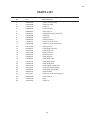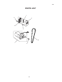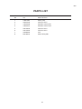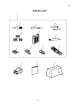
1
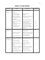
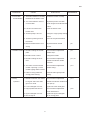
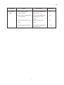
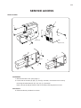
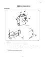
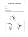
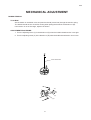
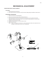
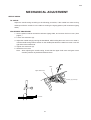
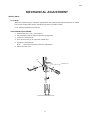
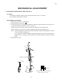
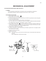
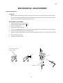
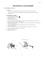
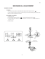
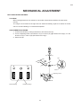
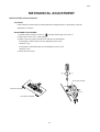
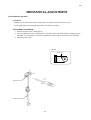
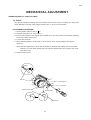
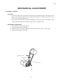
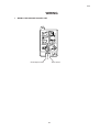
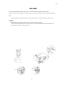
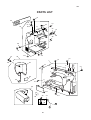
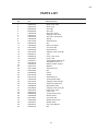
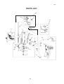
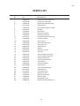
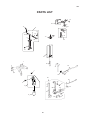
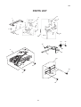
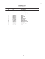
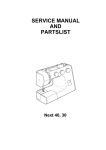
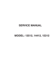
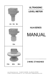
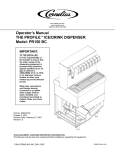
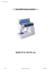
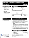
SERVICE MANUAL
PARTS LIST
MODEL 920
CONTENTS
WHAT TO DO WHEN ................................................................................................. 1-3
SERVICE ACCESS
FACE COVER ............................................................................................................... 4
FRONT COVER ............................................................................................................ 5
REAR COVER .............................................................................................................. 6
MECHANICAL ADJUSTMENT
TOP TENSION .............................................................................................................. 7
BOBBIN TENSION ........................................................................................................ 8
PRESSER BAR HEIGHT AND ALIGNMENT ................................................................ 9
NEEDLE SWING ......................................................................................................... 10
NEEDLE DROP .......................................................................................................... 11
CLEARANCE BETWEEN NEEDLE AND HOOK (NO.1) ............................................ 12
CLEARANCE BETWEEN NEEDLE AND HOOK (NO.2) ............................................ 13
FEED DOG HEIGHT ................................................................................................... 14
NEEDLE BAR HEIGHT ............................................................................................... 15
NEEDLE TIMING TO SHUTTLE ................................................................................. 16
DISTORTED PATTERN .............................................................................................. 17
BUTTONHOLE FEED BALANCE ............................................................................... 18
BARTACK FEED OF BUTTONHOLE ......................................................................... 19
BUTTONHOLE FUNCTION ........................................................................................ 20
DISENGAGEMENT OF CAM FOLLOWER ................................................................ 21
MOTOR BELT TENSION ............................................................................................ 22
WIRING ....................................................................................................................... 23
OILING ........................................................................................................................ 24
PARTS LIST ........................................................................................................... 25-43
920
WHAT TO DO WHEN
CONDITION
1. Skipped
stitches
CAUSE
HOW TO FIX
1. Needle is not inserted
REFERENCE
Insert the needle properly.
properly.
2. Needle is bent or blunt.
Change the needle.
3. Incorrectly threaded.
Rethread.
4. Needle or thread are
Use appropriate needle thread
inappropriate for the fabric
for fabric being sewn.
being sewn.
5. Sewing on stretch fabric.
Use a #11 blue tip needle.
6. Inappropriate needle bar
See mechanical adjustment
height.
p.15
"needle bar height".
7. Inappropriate needle to
See mechanical adjustment
hook timing.
p.16
"needle timing to shuttle".
8. Inappropriate needle to
See mechanical adjustment
hook clearance.
p.12,13
"clearance between needle
and hook".
2. Fabric is not
1. Incorrect feed dog height.
See mechanical adjustment
moving
p.14
"feed dog height".
2. Thread on bottom side of
Make sure to bring both needle
fabric is jammed up.
and bobbin thread under the
foot when start sewing.
3. The upper
thread breaks
3. Feed dog teeth are worn.
Change the feed dog.
1. Initial sewing speed is too
Start with medium speed.
fast.
2. Incorrectly threaded.
Thread correctly.
3. Needle is bent or blunt.
Change the needle.
4. Upper thread tension is too
Adjust the upper thread
strong.
tension.
5. Needle size is inappropriate
Use appropriate needle and
for the fabric being sewn.
thread for fabric being sewn.
6. Needle eye is worn.
Change the needle.
7. Needle hole of needle plate
Replace the needle plate.
is worn or burred.
1
p.7
920
CONDITION
4. The bobbin
thread breaks
CAUSE
HOW TO FIX
1. The bobbin thread is incorrectly
REFERENCE
Thread the bobbin correctly.
threaded in the bobbin case.
2. Too much thread is around
Adjust the position of bobbin
on the bobbin.
winder stopper and rethread the
bobbin.
3. Lint has corrected in the
Clean the bobbin case.
bobbin case.
4. Thread quality is too low.
Change to a high quality sewing
thread.
5. Thread is jamming around
Clear out the jammed thread.
the bobbin.
6. Bobbin thread tension is too
Adjust the bobbin thread
strong.
p.8
tension.
5. Needle breaks 1. Needle is hitting the needle
See mechanical adjustment
plate.
p.11
"needle drop".
2. Needle is bent or blunt.
Change the needle.
3. Needle is hitting the hook
See mechanical adjustment
race.
p.12,13
"clearance between needle
and hook".
4. The fabric moves while the
See mechanical adjustment
needle is piercing it, or the
p.10
"needle swing".
needle zigzags while in fabric.
5. Fabric is being pulled too
Guide the fabric gently while
strongly while sewing.
6. Noisy
operation
sewing.
1. Backlash between the shuttle
See mechanical adjustment
hook gear and lower shaft
"clearance between needle and
gear is too wide.
hook (No.2)".
2. Lower shaft gear is loose.
Tighten the lower shaft gear.
3. Inappropriate belt tension.
See mechanical adjustment
"motor belt tension".
4. Upper shaft gear is loose.
Tighten the upper shaft gear.
5. Not enough oil.
Oil all moving parts.
2
p.13
p.22
920
CONDITION
7. Deformation
pattern
CAUSE
HOW TO FIX
1. Inappropriate zigzag
See mechanical adjustment
synchronization.
REFERENCE
p.10
"needle swing".
2. Inappropriate disengagement
of cam follower.
See mechanical adjustment
p.21
"disengagement of cam
follower".
3. Upper thread tension is too
Adjust the upper thread
tight.
p.7
tension.
4. Inappropriate feed balance.
See mechanical adjustment
“distorted pattern”.
3
p.17
920
SERVICE ACCESS
FACE COVER
(A)
(B)
TO REMOVE
1. Remove the face cover by removing the cap (A) and screw (B).
TO ATTACH
2. Attach the face cover with the screw, and then, replace the cap.
4
920
SERVICE ACCESS
FRONT COVER
G
A
Cap
H
F
E
Front cover
Rear cover
G
I
C
D
B
K
J
TO REMOVE
1. Remove the face cover. (See page 4.)
2. Loosen the set screws (A), (B), (C), and (D), and then, remove the front cover by
removing the setscrews (E), (F), (G), (H), (I), (J) and (K).
Note: Unhook the tab (K) from the rear cover when removing the front cover.
TO ATTACH
3. Follow the above procedure in reverse.
5
920
SERVICE ACCESS
REAR COVER
A
B
D
Rear cover
F
E
C
TO REMOVE
1. Remove the face cover and front cover. (See page 4, 5.)
2. Loosen setscrews (A), (B), and (C), and remove setscrews (D), (E), and (F).
3. Pull up the spool pins. Remove the machine socket. Remove the rear cover clearing the
presser foot lifter from the slit on the cover.
TO ATTACH
4. Follow the above procedure in reverse.
6
920
MECHANICAL ADJUSTMENT
TOP TENSION
TO CHECK:
The standard upper hread tension should be 65-95g when pulling the thread (cotton thread
#50) in the direction of (B) with setting the tension dial at "3". (Make sure the foot should be
lowered.)
If the tension is out of the standard range, adjust it as follows:
ADJUSTMENT PROCEDURE:
1. Remove the front cover unit. (See page 5.)
2. Turn the adjusting nut (C) in the direction of (D) when the upper thread tension is too tight.
Turn the adjusting nut (C) in the direction of (E) when the upper thread tension is too loose.
3. Attach the front cover unit.
C
B
E
D
7
920
MECHANICAL ADJUSTMENT
BOBBIN TENSION
TO CHECK:
Set the bobbin in the bobbin case and pass the thread (cotton #50) through the tension spring.
The bobbin thread tension should be 45-55g when pulling the thread in the direction of (B).
If the tension is out of the range, adjust it as follows:
ADJUSTMENT PROCEDURE:
1. Turn the adjusting screw (C) in the direction of (D) when the bobbin thread tension is too tight.
2. Turn the adjusting screw (C) in the direction of (E) when the bobbin thread tension is too loose.
(B)
Cotton thread #50
(E)
(D)
(C)
8
920
MECHANICAL ADJUSTMENT
PRESSER BAR HEIGHT AND ALIGNMENT
TO CHECK:
1. Raise the presser foot lever (A).
2. The distance between the presser foot (D) and the needle plate (E) should be 6.0mm (0.24").
ADJUSTMENT PROCEDURE:
1. Remove the face cover. (See page 4.)
2. Remove the setscrew (B) and take the lamp socket off.
3. Raise the presser foot lever (A) and loosen the setscrew (C) on the presser bar holder.
Adjust the distance between the presser foot (D) and the needle plate (E) to 6.0mm (0.24").
4. Tighten the setscrew (C) securely.
5. Tighten the setscrew (B) to secure the lamp socket.
6. Attach the face cover.
Note: When you tighten the setscrew (C), make sure that both sides of the presser foot are
parallel to the feed dog slots (F) on the needle plate.
(A)
(F)
(B)
(C)
(D)
(E)
6.0mm
9
920
MECHANICAL ADJUSTMENT
NEEDLE SWING
TO CHECK:
Adjust the needle swing according to the following procedure, if the needle bar starts moving
sideways while the needle is in the fabric at sewing the zigzag pattern (with maximum zigzag
width).
ADJUSTMENT PROCEDURE:
1. Set the pattern selector dial with maximum zigzag width, and remove the front cover. (See
page 5.)
2. Loosen two setscrews (A).
3. Adjust the needle swing by turning the handwheel, while holding the worm so as not to rotate it,
until the needle swing starts at 2-3mm on the needle plate after the needle has come out of the
right side of the needle hole.
4. Tighten two setscrews (A).
5. Attach the front cover.
Note: After adjusting the needle swing, check that the upper shaft worm and gear rotate
smoothly without any backlash between them.
Gear
Upper shaft worm
(A) (2 PCS.)
2–3 mm
10
920
MECHANICAL ADJUSTMENT
NEEDLE DROP
TO CHECK:
When the needle swings in maximum zigzag width, the distance between the both ends of needle
hole on the needle plate and the needle drop positions should be equal.
If not, make an adjustment as follows:
ADJUSTMENT PROCEDURE:
1. Remove the face cover. (See page 4.)
2. Set the pattern selector dial at maximum zigzag width.
3. Loosen the setscrew (A).
4. Turn the eccentric pin to adjust the needle drop.
5. Tighten the setscrew (A).
Note:
Check the hook timing after this adjustment.
6. Attach the face cover.
(A)
Eccentric pin
Both clearance should be equal
11
920
MECHANICAL ADJUSTMENT
CLEARANCE BETWEEN NEEDLE AND HOOK (NO.1)
TO CHECK:
The clearance between needle and shuttle race should be –0.05 to +0.10mm.
If not, make an adjustment as follows:
ADJUSTMENT PROCEDURE:
1. Remove the face cover. (See page 4.)
2. Set the pattern selector dial "
".
3. Loosen setscrew (A), and move the needle bar supporter in either direction of arrows (B or C)
to adjust the clearance between –0.05 to +0.10mm.
* When clearance is too wide, move the needle bar supporter to the direction (B).
* When clearance is too narrow, move the needle bar supporter to the direction (C).
Note: After this adjustment, check if the clearance between needle and needle plate is 0.15mm
or more as shown in figure (D).
If not, adjust the clearance between needle and shuttle race by using the method of
adjustment No.2 on page 13 after readjust the clearance between needle and needle
plate.
4. Attach the face cover.
(A)
(C)
(B)
Needle bar supporter
–0.05-+0.10 mm
FIigure D
Clearance between needle and needle
plate is more than 0.15 mm
12
920
MECHANICAL ADJUSTMENT
CLEARANCE BETWEEN NEEDLE AND HOOK (NO.2)
TO CHECK:
Use this adjustment method No.2 if the clearance cannot be adjusted by method No.1.
The clearance between needle and shuttle race should be –0.05 to +0.10mm.
ADJUSTMENT PROCEDURE:
1. Set the pattern selector dial at "
".
2. Remove the rear cover. (See page 6.)
3. Loosen the setscrew (A) on lower shaft bushing and slide the gear about 0.5mm to the right to
make a slack between gears.
4. Lower the needle and loosen the two shuttle race screws (B).
Move the shuttle race unit axially either forward or backward to adjust the clearance between
the needle and the shuttle race in the range of –0.05 to +0.10mm.
5. Set the pattern select dial at "
". Turn the handwheel to check if the clearance between the
needle and inner edges of the shuttle race spring at the left and right needle drops are equal.
If not, make an adjustment by turning the shuttle race unit.
6. Tighten the two shuttle race screws (B).
7. Loosen the setscrew on lower shaft bushing and slide the gear back to its original position
while adjusting the backlash.
8. Tighten the setscrew (A) firmly.
9. Attach the rear cover.
Note: The rotary play of the hook driver should be 0.3mm or less and the lower shaft turns
smoothly.
After the adjustment, check the hook timing
(A)
–0.05 to +0.10 mm
Clearance should be equal
Needle
Shuttle race
Setscrews (B) (2 pcs.)
Lower shaft
bushing (front)
13
Shuttle race spring
920
MECHANICAL ADJUSTMENT
FEED DOG HEIGHT
TO CHECK:
1. Lower the presser foot.
2. Turn the handwheel toward you until the feed dog comes to its highest position. The feed dog
height should be 0.75-0.90mm.
If it is not in the range, adjust as follows.
ADJUSTMENT PROCEDURE:
1. Open the shuttle cover.
2. Lower the presser foot and turn the handwheel toward you until the feed dog comes to its
highest position.
3. Loosen the setscrew (A) .
4. Turn the feed lifting pin to adjust the feed dog height (0.75-0.90mm).
5. Tighten the setscrew (A).
6. Turn the handwheel toward you to recheck the height of feed dog.
Needle plate
0.75–0.90 mm
(A)
Feed lifting pin
14
920
MECHANICAL ADJUSTMENT
NEEDLE BAR HEIGHT
TO CHECK:
When the tip of shuttle hook meets the left side of the needle in ascending travel of the needle
from its left and lowest position, the distance between the top of the needle eye and the tip of the
shuttle hook should be in the range of 2.9-3.5 mm.
ADJUSTMENT PROCEDURE:
1. Remove the face cover. (See page 4.)
2. Set the pattern selector dial at "
".
3. Open the shuttle cover.
4. Remove the shuttle race ring.
5. Turn the handwheel toward you until the tip of the shuttle hook meets the left side of the needle.
6. Loosen the lower shaft crank arm setscrews (A).
7. Adjust the height of the needle bar by moving the needle bar upward or downword without turning
it.
8. Toghten the setscrew (A).
9. Attach the shuttle race ring.
Tip of shuttle hook meets
left side of needle
2.9 - 3.5 mm
Needle bar
15
(A)
920
MECHANICAL ADJUSTMENT
NEEDLE TIMING TO SHUTTLE
TO CHECK:
The height of the needle point from its lowest point of travel should be in the range of
1.45-1.95 mm when the tip of the shuttle hook just meets the left side of the needle at the left
needle position.
ADJUSTMENT PROCEDURE:
1. Set the pattern selector dial at "
"
2. Remove the front cover. (See page 5.)
3. Open the shuttle cover.
4. Remove the shuttle race ring.
5. Turn the handwheel toward you until the tip of the shuttle hook meets the left side of the needle.
6. Loosen the lower shaft crank arm setscrews (A).
7. While holding the shuttle hook so it doesn't turn, turn the handwheel toward you until the needle
comes to its lowest position.
Turn the handwheel further to raise the needle about 1.7mm from its lowest position.
8. Tighten the setscrews (A).
9. Turn the handwheel toward you to check if the height is in the range of 1.45 - 1.95 mm.
If it is not in this range, repeat the above procedure.
10. Attach the shuttle race ring.
11. Attach the front cover.
Lower shaft crank arm
Lower shaft
1.45–1.95 mm
(A) (2 pcs.)
Lowest position
16
920
MECHANICAL ADJUSTMENT
DISTORTED PATTERN
TO CHECK:
If the stretch stitch patterns are distorted with setting the stitch length control at “
”.
(In case of being a difference between forward feeding and backward feeding during stretch stitch
patterns), make an adjustment as follows:
ADJUSTMENT PROCEDURE:
1. Remove the cap.
2. Set the pattern selector control at “
”, and the stitch length control at “
”.
3. Turn the stretch stitch adjusting screw in the direction of (C) when A > B, or in the direction of
(D) when A < B.
4. Mount the cap.
(C)
Cap
(D)
Notch
Strech stitch
adjusting screw
17
920
MECHANICAL ADJUSTMENT
BUTTONHOLE FEED BALANCE
TO CHECK:
When sewing buttonhole, the stitches on each side of buttonhole should be the same stitch
density.
The range of 9-12 stitches in the right side row "backward feeding" against 10 stitches in the left
side row "forward feeding" is considered acceptable.
ADJUSTMENT PROCEDURE:
1. Confirm the stitches by sewing buttonholes, and remove the cap.
2. Turn the adjusting screw in the direction of (C) in case of (A) (right stitches are rough), or in the
direction of (D) in case of (B) (left stitches are rough).
3. Attach the cap.
(D)
(C)
Cap
A
B
Notch
Adjusting screw
Forward feeding
Backward feeding
18
920
MECHANICAL ADJUSTMENT
BARTACK FEED OF BUTTONHOLE
TO CHECK:
If the material is feed forward or backward when sewing bartack on buttonhole, make an
adjustment as follows:
ADJUSTMENT PROCEDURE:
1. Set the pattern selector control at “
” and the stitch length control at “4”.
2. Remove the front cover. (See page 5.)
3. Place a piece of paper under the foot and turn the handwheel.
If the paper is feed forward, turn the adjusting screw in the
direction of (C).
If the paper is feed backward, turn the adjusting screw in the
direction of (D).
4. Mount the front cover.
(D)
(C)
ADJUSTING SCREW
FORWARD FEEDING
BACKWARD FEEDING
19
920
MECHANICAL ADJUSTMENT
BUTTONHOLE FUNCTION
TO CHECK:
Buttonholes should be about 3mm longer than the length set by the buttonhole foot.
If this length cannot be obtained, then check and adjust as follows:
ADJUSTMENT PROCEDURE:
1. Remove the face cover. (See page 4.)
2. Turn the adjusting screw in the direction of (A) if the buttonhole stitch length is longer than the
standard, or in the direction of (B) if the buttonhole stitch length is shorter than the standard.
3. Attach the face cover.
Standard
About 3mm
(A)
Adjusting screw
(B)
Buttonhole lever
20
920
MECHANICAL ADJUSTMENT
DISENGAGEMENT OF CAM FOLLOWER
TO CHECK:
Too narrow clearance between the cam follower and the top convex of zigzag cam may often
cause difficulty in turning of the pattern selector dial, or can not correct pattern.
ADJUSTMENT PROCEDURE:
1. Set the pattern selector dial "
".
2. Remove the front cover. (See page 5.)
3. Put the cam follower to the zigzag cam (straight cam), and also put the cam follower releasing
arm to the pattern select cam.
4. Loosen the setscrew.
5. Move adjusting plate in the direction of arrow until to touch to the releasing arm tighten
setscrew.
Note: After this adjustment, check that the clearance between the zigzag cam and the cam
follower is 0.3 mm when putting the cam follower releasing arm onto position (A) of pat
tern select cam.
6. Attach the front cover.
0.3mm
ZZ cam
Releasing arm
Setscrew
Pattern selector cam
Adjusting plate
Release arm
21
920
MECHANICAL ADJUSTMENT
MOTOR BELT TENSION
TO CHECK:
1. If the motor belt tension is too tight or too loose, it can cause a belt noise: If the tension is too
tight, it can cause the machine to run slowly and the motor to overload; if the tension is too
loose; it can cause the belt to jump.
2. The correct motor belt tension is when the deflection of motor belt is about 7mm (0.28") - 9mm
(0.36"). (when pushing the motor belt by finger with a 300 gram load.)
ADJUSTMENT PROCEDURE:
1. Remove the rear cover. (See page 6)
2. Loosen the setscrews (A) and (B).
3. Move the motor up or down to adjust the deflection about 7mm (0.28") - 9mm (0.36").
4. Tighten the setscrews (A) and (B).
Deflection 7-9mm
300g load
(A)
(B)
22
920
WIRING
1.
WIRING FOR MACHINE SOCKET UNIT
From lamp socket
From motor
23
920
OILING
Factory lubricated parts will provide years of household sewing without routine oiling.
However, whenever the machine is being serviced, check to see if any parts need to be lubricated.
OIL
Use good quality sewing machine oil at the points (A, B, C, D, E) indicated by black arrows.
GREASE
White grease is recommended for use on gears and cam surfaces.
It is an improved grease, and it can be used on the metal and plastic parts which points are
indicated by the white arrows (F,G, & H).
D
A
E
B
C
F
H
G
24
920
PARTS LIST
KEY
NO.
PARTS
NO.
DESCRIPTION
PARTS LIST
25
920
PARTS LIST
15
24
22
21
20
16
12
18
17
27
13
19
28
36
23
26
15
15
32
13
12
15
12
1
33
13
4
13
3
2
7
6 5
35
34
9
14
8
29
10
11
25
40
13
37
39
38
26
30
7
31
920
PARTS LIST
KEY
NO.
PARTS
NO.
1
2
3
4
5
6
7
8
9
10
11
12
13
14
15
16
17
18
19
20
21
22
23
24
25
26
27
28
29
30
31
32
33
34
35
36
37
38
39
40
304601307
304001105
652302004
652205006
736007009
000076317
735013005
730006000
000101404
000061205
739004005
000115205
000081005
000121905
653006101
304605079
304029361
730501011
000160102
735016307
000071013
000101828
843014004
304030804
639161008
000101703
745031000
000107307
304501007
739064003
000198604
304613003
304051007
840602006
724025006
000115607
735616200
735002001
000097901
000061319
DESCRIPTION
Rear cover (unit)
Rear cover
Spool pin
Spool pin
Spool pin spring
Tapping screw 3x10
Spool pin spring base
Spring
Setscrew 4x6
Nut
Bed cover plate
TP screw 4x6
Setscrew 4x8
Tapping screw 4x12 (B)
Cap
Front cover (unit)
Front cover
Thread guide plate (unit)
Adjustable lock nut 4
Bobbin winder stopper
Washer
Setscrew 4x16
Nut
Panel
Sticker
Setscrew 4x12
Thread guide plate
Tapping screw 3x8 (B)
Extension table (unit)
Bed rubber base
Tapping screw 4x14 (B)
Face cover (unit)
Face cover
Thread cutter (unit)
Reflex sticker
TP screw 4x8
Rubber base (unit)
Rubber base
Flat screw M5x18
Nut
27
920
PARTS LIST
33
30
23
25
1
19
32
31
7
20
21
15
22
2
17
23
28
8
13
29
14
24
11
26
18
9
12
25
10
4
3
16
15
5
6
27
28
920
PARTS LIST
KEY
NO.
PARTS
NO.
1
2
3
4
5
6
7
8
9
10
11
12
13
14
15
16
17
18
19
20
21
22
23
24
25
26
27
28
29
30
31
32
33
305604004
735221008
735222009
000101404
735025000
000138307
735026001
735027002
735028003
000111500
735029004
000001609
735030008
000013903
000081005
000070506
301612003
660106001
304610000
739017001
304045008
739019003
000002105
304603000
000103808
304008009
000101703
611510000
301505002
740613007
740050000
740051001
740620018
DESCRIPTION
Presser bar base plate (unit)
Presser bar base plate
Needle drop adjusting plate
Setscrew 4x6
Needle bar supporter stopper
Bolt 4x8
Presser bar
Presser bar spring
Presser bar bracket
Hexagonal socket screw 4x8
Presser foot lifter
Snap ring E-5
Tension release lever
Snap ring CS-5
Setscrew 4x8
Washer
Presser foot (unit)
Setscrew
Tension release arm (unit)
Tension release arm base
Tension release arm
Tension release spring
Snap ring E-3
Tension assembly
Setscrew 3x5
Top cover thread guide
Setscrew 4x12
Foot holder (unit)
Zigzag foot (unit)
BH lever base (unit)
BH lever base
BH adjusting lever
Presser bar base plate (unit)
29
920
PARTS LIST
14
24
23
14
21
8
13
11
36
12
13
37
17
9
22
10
15
16
1
25
3
2
20
4
7
18
2
19
26
35
32
4
31
5
30
15
33
28
27
23
6
29
30
34
920
PARTS LIST
KEY
NO.
PARTS
NO.
1
2
3
4
5
6
7
8
9
10
11
12
13
14
15
16
17
18
19
20
21
22
23
24
25
26
27
28
29
30
31
32
33
34
35
36
37
740007013
000081005
730024004
000101404
743634003
000009009
000053709
301610001
301032003
730022002
673022002
000070609
000002507
000111304
000111902
730503116
301504104
678084007
748021006
735119002
625506109
743664105
731511006
000002806
102408089
740617001
753629109
740047004
753027008
000023009
000113306
000160102
740048005
740049006
740052002
735504008
680032007
DESCRIPTION
Face cover set plate
Setscrew 4x8
Needle bar supporter spring
Setscrew 4x6
Lamp socket (unit)
Lamp 240v 15w
Cord tie band
Needle bar supporter (unit)
Needle bar supporter
Needle bar supporter pin
Wave washer
Plain washer
Snap ring E-4
Hexagonal socket screw 5x5
Hexagonal socket screw 3x4
Needle bar (unit)
Needle bar connecting stud (unit)
Eccentric pin
Zigzag rod plain washer
Zigzag rod
Thread take-up lever (unit)
Needle bar crank (unit)
Thread take-up lever pin (unit)
Snap ring E-6
#14 Needle
BH lever (unit)
BH lever (unit)
BH lever supporter
Friction spring
Spring pin
Socket screw 4x10
Adjustable lock nut 4
BH lever base plate
BH lever spring
BH shifting rod
Needle bar crank pin (unit)
Needle bar crank rod
31
920
PARTS LIST
15
19
16
20
14
1
21
18
11
9
17
7
10
12
8
4
13
28
5
6
29
30
10
25
31
25
24
22
27
26
23
32
3
2
920
PARTS LIST
KEY
NO.
PARTS
NO.
1
2
3
4
5
6
7
8
9
10
11
12
13
14
15
16
17
18
19
20
21
22
23
24
25
26
27
28
29
30
31
304607004
639113016
000810005
650070037
102073003
761052007
000036717
732025001
639095000
000111304
749011109
000111201
000022802
731312005
304609006
304042005
743011008
304044007
304043006
000161309
000110107
732003003
000172602
743029009
000030205
743019006
000023803
304612301
639097242
304050006
000107802
DESCRIPTION
Upper shaft (unit)
Clutch spring
Setscrew 4x8
Clutch cap
Setscrew
Setscrew
Thrust washer
Upper shaft front bushing
Ring
Hexagonal socket screw 5x5
Worm
Hexagonal socket screw 4x4
Spring pin 2x12
Felt
Crank rod (unit)
Feed cam
Crank rod
Crank cam
Crank cam plate
Tapping screw 3x12
Hexagonal socket screw 5x5
Upper shaft rear bushing
Setscrew 5x8
Felt
Snap ring E-8
Belt wheel
Spring pin
Handwheel (unit)
Handwheel
Balance weight
Tapping screw 3x10 (B)
33
920
PARTS LIST
17
6
1
7
5
3
21
9
2
8
5
3
22
10
25
20
24
23
5
4
28
33
3
26
16
27
18
13
11
14
19
31
15
12
29
32
5
34
30
5
35
14
34
920
PARTS LIST
PARTS
NO.
KEY
NO.
1
2
3
4
5
6
7
8
9
10
11
12
13
14
15
16
17
18
19
20
21
22
23
24
25
26
27
28
29
30
31
32
33
34
35
304006007
740011009
000002105
740010008
000081005
740602405
735501108
740003101
740042009
000002806
304604702
303028002
303051004
000103808
736015000
739063002
304611104
000014007
304007204
000160102
648010009
739020007
735077007
735073003
000013800
745052007
000101301
740125007
304608201
000081500
303078007
304063002
000172602
304063002
304028201
DESCRIPTION
Handle
Handle shaft
Snap ring E-3
Handle supporter
Setscrew 4x8
Bobbin winder base plate (unit)
Bobbin winder arm (unit)
Bobbin winder base plate
Bobbin winder arm spring
Snap ring E-6
Zigzag mechanism (unit)
Index spring (1)
Index spring (2)
Setscrew 3x5
R button shaft
R button spring
Feed regulator (unit)
Snap ring CS-4
R button
Adjustable lock nut 4
Setscrew
Feed regulating rod
Feed regulating body spring
Plain washer
Snap ring CS-6
Reverse link
Setscrew 5x10
Feed regulator spring
Button base (unit)
Setscrew 3x12
Spring
Pattern indicator plate
Setscrew 5x8
Stitch length button
Stitch width button
35
920
PARTS LIST
12
2
3
5
7
13
14
9
4
1
11
4
4
6
15
19
8
8
16
10
18
8
17
8
36
920
PARTS LIST
PARTS
NO.
KEY
NO.
1
2
3
4
5
6
7
8
9
10
11
12
13
14
15
16
17
18
19
744004001
681009101
735950003
000110107
000036201
735233003
735061101
000111304
735236006
102261000
822070003
735234004
639036003
639037004
000001609
735610101
532096007
647515006
000172602
DESCRIPTION
Needle plate
Setscrew
Lower shaft gear (unit)
Hexagonal socket screw 5x5WP
Washer 8-0.5
Bushing
Feed lifting cam
Hexagonal socket screw 5x5
Lower shaft
Bobbin
Felt
Bushing
Lower shaft crank arm
Pin
Snap ring E-5
Shuttle race body (unit)
Shuttle hook
Bobbin case (unit)
Setscrew 5x8
37
920
PARTS LIST
21
15
1
28
4
5
6
2
6
10
25
11
26
12
13
27
8
7
10
3
11
6
19
14
9
20
6
12
17 18
22
23
24
38
16
920
PARTS LIST
KEY
NO.
PARTS
NO.
1
2
3
4
5
6
7
8
9
10
11
12
13
14
15
16
17
18
19
20
21
22
23
24
25
26
27
28
735612000
735078008
735079009
735080003
000002507
000111201
735081004
735082005
735083006
735084007
735085008
000101404
301609007
301027005
743013000
000097200
735087000
735088001
730061003
735090006
102141003
740013001
739022009
000081119
735071104
000002806
735276008
743012009
DESCRIPTION
Feed rock shaft (unit)
Feed rock shaft
Feed bar
Feed bar shaft
Snap ring E-4
Hexagonal socket screw 4x4
Feed dog
Setscrew
Feed bar spring
Feed rock shaft center
Feed rock shaft center plate
Setscrew 4x6
Feed lifting arm (unit)
Feed lifting arm
Feed rod spring
Setscrew 4x12
Feed lifting pin
Feed lifting roller
Feed lifting spring
Feed lifting shaft
Feed regulator slide block
Drop feed selecting plate
Feed lifting shaft holder
Setscrew 4x6
Feed rock shaft connecting pin
Snap ring E-6
Ring
Feed rod
39
920
PARTS LIST
7
6
3
4
5
8
1
2
40
920
PARTS LIST
KEY
NO.
PARTS
NO.
DESCRIPTION
1
2
3
4
5
6
7
8
743611004
000201209
739503308
739037007
000103509
000107802
000060802
650166019
Motor (unit)
Setscrew 5x12
Machine socket (unit)
Machine socket cover
Setscrew 4x10
Setscrew 3x10
Nut
Motor timing belt
41
920
PARTS LIST
1
2
4
3
6
5
7
8
12
11
10
9
13
42
14
920
PARTS LIST
KEY
NO.
PARTS
NO.
1
2
3
4
5
6
7
8
9
10
11
12
13
14
304870309
820832005
647803004
647808009
102261000
540401026
802424004
737801015
611406002
731806001
740801004
042870308
304800283
741811000
DESCRIPTION
Accessory set
Screw driver (Large)
Screw driver (Small)
Buttonhole opener
Bobbin
Needle set
Brush
Buttonhole foot
Zipper foot
Straight stitch foot
Buttonhole foot (unit)
Foot control
Instruction book
Cover
43