1
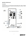
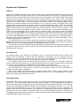
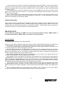
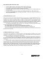
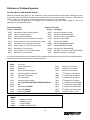
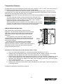
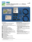
Master Controller 2.0v24
Reverse Cycle Defrost System
Installation & Operations Manual
An Electronic Microprocessor-Based
Electric/Mechanical Expansion Valve Refrigeration Control System
With TCP/IP Internet Monitoring Feature
May 2015
PN 888-88889
©2015 Master-Bilt Products, an unincorporated division of Standex International Corporation. All rights reserved.
Printed in U.S.A.
IMPORTANT NOTICES
• Read this manual before installing your Master Controller 2.0 system.
Keep the manual and refer to it before doing any service on the
equipment. Failure to do so may result in personal injury or waive
warranty of damaged equipment.
• Modifications to existing equipment are subject to approval by Master-Bilt
and must be explicitly written. There are no implied flexibilities designed into
this product.
• The following points apply unless overwritten and approved by the MasterBilt engineering department:
o Maximum distance of wires between the evaporator and the Master
Controller 2.0 MUST not exceed 40 ft.
o The Master Controller 2.0 MUST be mounted on the neighborhood of
the vestibule entrance door for below -40oF extra low temp freezer
o All sensor wires MUST be in separate metal conduit from power wiring
and control wiring for below -40oF extra low temp freezer
• Due to continuous product enhancements, Master-Bilt reserves the right to
make engineering changes and change specifications for product
improvement without notice.
2
TABLE OF CONTENTS
INTRODUCTION .................................................................................................................. 4
WARNING LABELS AND SAFETY INSTRUCTIONS .......................................................... 5
APPLICATIONS .................................................................................................................... 5
MASTER CONTROLLER LAYOUT ...................................................................................... 6
Description ................................................................................................................. 7
Factory-Mounted Parts ............................................................................................... 8
Features ..................................................................................................................... 9
Sequences of Operation .......................................................................................... 10
START UP ......................................................................................................... 10
OFF MODE ........................................................................................................ 10
COOL MODE ...................................................................................................... 10
DEFROST MODE ................................................................................................. 11
Scheduled Defrost ..................................................................................... 11
Demand Defrost ........................................................................................ 12
Manual Defrost ......................................................................................... 12
COIL DRAIN MODE .............................................................................................. 12
FAN DELAY MODE ............................................................................................... 12
SAFETY MODE ................................................................................................... 12
Multiple Evaporator Configuration ............................................................................ 13
BOND CONTROLLERS FROM FRONT PANEL .............................................................. 14
SYCHRONIZE MODE (peer to peer) ........................................................................... 14
ALTERNATING MODE ........................................................................................... 14
Definition of On-Board Symbols ............................................................................... 15
STATUS, DEFAULT AND READING DISPLAY ............................................................... 15
VARIABLES ....................................................................................................... 15
MANUAL MODE................................................................................................... 15
TYPICAL SETPOINTS PARAMETER .......................................................................... 16
ALARM DISPLAY ................................................................................................. 17
Setting Parameters by On-Board Pushbuttons ........................................................ 17
Temperature Sensors .............................................................................................. 19
SENSOR SERVICE INSTRUCTIONS .......................................................................... 19
Pressure Transducer ............................................................................................... 20
Charging the Master Controller 2.0 Refrigeration System ....................................... 21
Technical Notes ....................................................................................................... 22
REVERSE CYCLE DEFROST ........................................................................................... 23
General Information ................................................................................................. 23
Advantages .............................................................................................................. 23
Factory-Installed Parts ............................................................................................. 23
Eliminated Parts ....................................................................................................... 24
Defrost Time ............................................................................................................ 24
Charging a Master Controller 2.0 System Equipped with Reverse Cycle Defrost ... 24
ELECTRIC WIRING............................................................................................................ 24
TYPICAL WIRING DIAGRAMS ....................................................................................... 25-27
TROUBLESHOOTING GUIDE ........................................................................................... 28
Troubleshooting Electric Expansion Valve .............................................................. 29
MASTER-BILT PART NUMBERS ....................................................................................... 29
3
INTRODUCTION
Thank you for purchasing a Master-Bilt Master Controller 2.0 for Electric or Reverse Cycle Defrost system. This
manual contains important instructions for installing, using and servicing the system as well as a parts list. Read this
manual carefully before installing or servicing your equipment.
DANGER
Improper or faulty hook-up of electrical components of the refrigeration units can result in severe injury or
death.
All electrical wiring hook-ups must be done in accordance with all applicable local, regional or national
standards.
NOTICE
Installation and service of the refrigeration and electrical components must be performed by a refrigeration
mechanic and/or a licensed electrician.
The portions of this manual covering refrigeration and electrical components contain technical instructions intended
only for persons qualified to perform refrigeration and electrical work.
This manual cannot cover every installation, use or service situation. If you need additional information, call or write
us:
Customer Service Department
Master-Bilt Products
Highway 15 North
New Albany, MS 38652
Phone: 800-684-8988
Fax: 866-882-7629
Email: [email protected]
4
WARNING LABELS AND SAFETY INSTRUCTIONS
This is the safety-alert symbol. When you see this symbol, be alert to the potential for personal
injury or damage to your equipment. Be sure you understand all safety messages and always
follow recommended precautions and safe operating practices.
NOTICE TO EMPLOYERS
You must make sure that everyone who installs, uses or services your refrigeration is thoroughly familiar
with all safety information and procedures.
Important safety information is presented in this section and throughout the manual. The following signal words are
used in the warnings and safety messages:
DANGER:
Severe injury or death will occur if you ignore the message.
WARNING: Severe injury or death can occur if you ignore the message.
CAUTION: Minor injury or damage to your refrigeration system can occur if you ignore the message.
NOTICE:
This is important installation, operation or service information. If you ignore the message, you
may damage your refrigeration system.
The warning and safety labels shown throughout this manual are placed on your Master-Bilt refrigeration
system at the factory. Follow all warning label instructions. If any warning or safety labels become lost or
damaged, call our customer service department at 800-684-8988 for replacements.
This label is on the housing of the Master Controller 2.0 typically located on an evaporator coil.
APPLICATIONS
Master Controller 2.0 Electric/Reverse-Cycle Defrost systems are designed to control Master-Bilt made condensing
units and evaporators for freezer and cooler applications. Each system contains a condensing unit, evaporator(s)
with Master Controller 2.0 board(s), Mechanical/electric expansion valve(s), pressure transducers, temperature
sensors, reverse cycle valve and operational controls.
5
MASTER CONTROLLER
Description
The Master Controller 2.0 is a custom-designed microprocessor-based electronic controller for Master-Bilt
refrigeration products. The controller caple to control an electric expansion valve in response to evaporator
superheat and return air temperature. The hardware and input/output descriptions and connections of a Master
Controller 2.0 are shown below.
Figure 1 . Master Controller 2.0 Board Layout.
6
•
SEI or SER Terminals. Sporlan SEI and SER type electric expansion valves are currently used for all applications.
There are 1596 nominal steps for entire valve stroke.
•
Pressure Transducer is mounted at the evaporator suction header to measure saturated suction pressure in absolute
value but displayed in gauge pressure in PSIG. The suction pressure is converted to evaporating temperature. The
difference between outlet temperature and evaporating temperature is the true superheat displayed as “SUPH”.
•
Defrost Termination Temperature Sensor TS3 is mounted downstream of the distributor tube after the valve and
close enough to the evaporator coil to measure defrost termination temperature during defrost cylce. Figure 2 on the
previous page shows the sensor locations of the evaporator and the controller.
•
Outlet/Fan Cut-In Temperature Sensor TS1 is mounted on the suction line about 6” to 10” away from the evaporator
to measure outlet temperature during cooling cycle and to serve as evaporator fan cut-in temperature sensor. The
sensor is at a 2 or 10 o’clock position on the suction line. The default value of the fan cut-in temperature is pre-set at
o
20 F for commercial refrigeration application.
•
Room Temperature Sensor TS2 is typically mounted with a plastic tie at the drain pan on the side of the evaporator
return air. It is located around the middle of the evaporator to allow even air flow across it. If necessary, it can be
relocated to a spot with better representation of the cold room temperature.
•
Four Digit LED Display is used to show status of the controller, set point values and temperatures.
•
Green Amber and Red LED Status Indicators. The green LED will be on when the compressor relay is energized.
The green LED will blink when the air temperature is satisfied, but the compressor minimum run timer or minimum off
timer has not yet timed out. The red LED indicates a critical alarm has occurred (Low Pressure alarm). The amber
LED indicates all other alarms.
•
Six Push Buttons are used to display set points and status as well as to reset operational parameters like room
temperature, defrost mode, number of defrosts, etc. Their functions can be also performed by using the TCP/IP
interface.
•
Two 20 Amp, 240 VAC NC/NO Relays. One relay is used for the defrost heater when the heater load is less than 20
amp. It will be wired to defrost heater contactor when heater load is over 20 amp or three phase heaters. For a reverse
cycle defrost system, it is wired to a 40VA transformer that provides 24VAC power to the reversing valve
solenoid coil. The other relay is used to switch evaporator fans ON and OFF. A fan contactor will be used if the fan
motor is lager than 10 amps or three phase or the voltage is different from control voltage.
•
One 3 Amp, 240 VAC NC/NO Relay is used for the compressor contactor or liquid line solenoid.
•
One 3 Amp, 240 VAC NC/NO Relay is an option for an external alarm system. The customer can decide what type of
a physical alarm is used. This relay is energized when the controller is powered on. Whenever the controller gives an
alarm, the relay will be de-energized. For example, a technician can connect a phone alarm system to this relay. When
there is an alarm, the alarm system can dial in his pager or cellular phone.
•
One RJ-45, TCP/IP Ehternet Port is used for Peer to Peer system or an alternating system communication requiring
ethernet connection. It is also used to communicate with a Laptop, internal network, or the internet.
•
Power Input 120 or 208/240 VAC. For 120 VAC input, jumper between pins 1 and 2 of ‘Voltage Jumper’ connector and jumper
between pins 3 and 4 of ‘Voltage Jumper’ connector. For 208/240 VAC input, jumper between pins 2 and 3 of ‘Voltage Jumper’
connector.
7
Evaporator
Evap Coil In/
Defrost Temp. Sensor
Liquid Line
Pressure
Transducer
Suction Line
Distributor
Evap out / Fan Delay
Temp Sensor
Room Temp Sensor
Electric
Expansion
Valve
T1 T2 T3
ADVANCED MASTER CONTROLLER
Figure 2.
Factory-Mounted Parts
•
•
•
A controller board, an Electric/Mechanical expansion valve, a pressure transducer, and three temperature
sensors for single evaporator system (standalone or alternating) or peer (multiple evaporator system)
evaporator are pre-mounted at the factory. . For a multiple evaporator system, only 1 evaporator is required
to have an air temperatue sensor. For reverse cycle defrost, a 24 VAC 40VA transformer is mounted at
standalone or master evaporator to provide power 24VAC to the four-way reversing valve mounted in the
condensing unit. The control circuit and power supply are pre-wired to the terminal board of the evaporator.
The board is molded in epoxy to avoid excessive moisture in cold room.
A 4-way reversing valve, operating at 24 VAC, is installed in a reverse cycle defrost equipped unit. A
transformer is also installed in one of the evaporators to supply 24VAC to the 4-way reversing valve.
Peer to Peer controls can be connected directly to each other, using a CAT-5E cable, if there are only 2
controllers. The controllers must be connected through an Ethernet switch or router if 3 or more controllers
are on the system. The controllers must be bonded together. A technician should install the CAT-5E cable
from the controllers to the Ethernet switch or router and bond the controllers. All components are factory
tested. A technician should check all the wiring and settings for proper operation after installation.
8
Features
•
One of the most energy-saving features of the Master Controller 2.0 Reverse Cycle Defrost system is free
floating head pressure. A head pressure control is not installed on Master Controller 2.0 systems. Without
this control, compressors work at the highest efficiency at the lowest possible condensing pressure rather
than at the limited pressure level typically found in conventional systems using a head pressure control valve
for low ambient environments. For more energy saving information, go to www.masterbilt.com/pdfs/master_controller_vs_standard_system.pdf.
•
Option for Mechanical Expansion Valve, or Electronic Expansion Valve
With the electric expansion valve; the refrigerant flow of the electric expansion valve is modulated by the
true superheat, or the difference of evaporator outlet and evaporating temperatures.
The room temperature sensor replaces the conventional temperature control. The temperature is set with
the pushbuttons on the Master Controller 2.0 board or through the web page. The default temperature must
be checked during the first startup of the machine against actual application temperature. Default must be
re-set to actual application temperature if there is a discrepancy.
Evaporator Fans cycle during compressor off mode, and options for electric defrost heaters to cycle on-andoff durring defrost for addition energy saving.
The on-board timer is used for run time control and scheduling defrosts. No mechanical defrost timer is
necessary for this system. Once the power is turned on, the timer starts counting.
The Master Controller 2.0 has the capability to perform scheduled defrost or demand defrost for either
Reverse Cycle hot gas defrost, or Electric defrost.
o When the scheduled defrost scheme is chosen, the on-board timer is used for scheduled defrosts.
The system works in the same fashion as a regular conventional system with mechanical defrost
timer.
o When the demand defrost is chosen, the controller will not initiate a defrost unless it is needed. The
low temperature system is pre-set with demand defrost.
The demand defrost scheme is a pioneer design by Master-Bilt for freezer applications. Extensive lab tests
indicate that many unnecessary defrosts are eliminated and energy consumption reduced when using
demand defrost compared to using a conventional refrigeration system equipped with a mechanical defrost
timer.
The operational status of modes, room temperature and alarms is displayed on the four-digit on-board
display.
Manual defrost is available on standalone and Peer to Peer systems.
All components are factory-mounted, pre-wired and tested to save on-site installation labor and reduce
chance of installation errors.
o
The superheat set point has a wide adjustability range 5° to 20 F. This range allows the controller to meet
different customers’ needs, and require less refrigerant charge for winter operation than conventional
refrigeration unit when no head pressure valve is installed in the condensing unit.
The controller can be used in low, medium and high temperature applications. The internal programming will
recognize the input of room temperature set point (RMSP) and automatically select appropriate segments of
the program for the application.
The patented reverse cycle defrost control (United States Patent 7,073,344) reduces defrost energy usage
by up to 80% and decreases defrost time from 20-45 minutes (freezer equipped with electric heaters) to 3-5
1
minutes in a freezer or 1 /2 – 2 minutes in a cooler with a completely clean defrost.
Maximum operating suction pressure can be controlled by the electric expansion valve eliminating the
crankcase pressure regulator for some applications.
Minimum operating suction pressure provides additional compressor protection.
•
•
•
•
•
•
•
•
•
•
•
•
•
•
9
Sequences of Operation
START UP
When power is applied to the board, the controller closes the valve. The controller will display ‘STUP’ on its four-digit
display for five seconds. It will then display ‘CKFN’ on the four-digit display for 10 seconds. The evaporator fans will
be on for the first 15 seconds allowing a service technician time to check them. The controller will then turn the fans
off and check each sensor. The controller will check the pressure transducer for a short or open. It will display
‘CKPR’ on the four-digit display for three seconds. If the sensor fails, the controller will display an alarm and go to
safety mode for a failed sensor. If the sensor passes, it will display ‘OKPR’ on the four-digit display for three
seconds. The controller will check the sensor connected to ‘TS1’ for a short or an open. It will display ‘CKT1’ on the
four-digit display for three seconds. If the sensor fails, the controller will display the alarm ‘STSA’ on the four-digit
display and go to safety mode for a failed suction sensor. If the sensor passes, it will display ‘OKT1’ on the four-digit
display for three seconds. The controller will check the sensor connected to ‘TS2’ for a short or an open. It will
display ‘CKT2’ on the four-digit display for three seconds. If the sensor fails, the controller will display the alarm
‘ATSA’ on the four-digit display and go to safety mode for a failed air sensor. If the sensor passes, it will display
‘OKT2’ on the four-digit display for three seconds. The controller will check the sensor connected to ‘TS3’ for a short
or an open. It will display ‘CKT3’ on the four-digit display for three seconds. If the sensor fails, it will display the alarm
‘CTSA’ on the four-digit display and go to safety mode for a failed coil temperature sensor. If the sensor passes, it
will display ‘OKT3’ on the four-digit display for three seconds. If all sensors pass, the controller will display ‘CKFH’
on the four-digit display for six seconds.
The controller will not go into defrost during the preceding start up procedure. It will check the number of
defrosts per day (DFPD) and time_of_day (HOUR, MIN). If it is time for the controller to be in defrost, it will start in
DEFROST mode. If not, the controller will start in COOL(REFR) mode after fan delay.
The set points are stored in EEPROM (Electrically Erasable Programmable Read Only Memory). Batteries are
not required to store the new set points. If power is lost, the set points which were in the controller at that time will be
used when power is restored.
OFF MODE (OFF)
The controller starts in OFF mode by fully closing the valve. The controller will keep the valve closed for the
minimum OFF Time (MOTM) in order to keep the compressor in pumpdown or off for a minimum amount of
time.When the room temperature reaches the cut-in set point (room temperature set point “RMSP” plus the
temperature difference set point “ADIF”), the controller goes to COOL mode (REFR).
If a scheduled defrost scheme is selected, while the controller is in OFF mode, it is constantly checking the
number of defrosts per day and the time_of_day and calculating the time for defrost. When the time_of_day is right
for a defrost, it will immediately go into DEFROST mode right after the current OFF mode.
If the demand defrost scheme is selected, defrost will be checked and initiated only during the COOL mode.
After the Minimum OFF Time is timed out and the room temperature reaches the Cut-In temperature, the
controller will go into COOL mode(REFR).
While in OFF MODE, the four-digit display on Master will show ‘OFF’ for three seconds, ‘RMTP’ for two
seconds, and the numerical display of the room temperature for five seconds. The four-digit display on controllers
without an air temperature sensor will show ‘OFF’.
COOL MODE (REFR)
The controller starts COOL mode by opening the valve. The condensing unit will start by a suction line low pressure
control cut-in. The electric expansion valve is modulated by the controller so that a preprogrammed superheat set
point is maintained during the refrigeration process. Actual superheat is the temperature difference of the evaporator
outlet and the evaporating temperature converted from the reading of the presssure transducer, or Tout-Tsat. The
controller will keep modulating the valve so the superheat will equal the superheat set point. Meanwhile, the
controller reads also the room air temperature TS2. When the room temperature is below the room temperature set
o
point (pre-set to -10 F for low temp), it goes back to OFF mode. All the time that the controller is in COOL mode, it
is constantly checking the criteria to determine if a defrost should be initiated. It will immediately go into DEFROST
mode (DEFR) when defrost criteria are met.
10
If the suction pressure is above the maximum operating pressure set point (MOP), the valve will modulate to
control the pressure at or below the maximum operating pressure set point (MOP). When the operating suction
pressure is lower than MOP, it will go back to superheat control. Suction pressure is used to calculate saturated
temperature (TSAT).
If the suction pressure is below the Minimum pressure set point (MNPR), the valve will close and the control
signal to the external relay will be turned off. It will resume normal operation when the pressure is above the
Minimum pressure set point.
While in COOL MODE, the four-digit display on Master will show ‘REFR’ for three seconds, ‘RMSP’ for two
seconds, and the numerical display of the room temperature for five seconds. The four-digit display on controllers
without an air temperature sensor will show ‘REFR’.
DEFROST MODE (DEFR)
There are two methods to determine if a defrost will be initiated for the Master Controller: scheduled defrost and
demand defrost. If the parameter “DINM” = “DEMD” and the number of defrosts per day ‘DFPD’ is set to 0, the
controller will do the demand defrost by default. If the parameter “DINM” = “SCHD” and the number of defrosts per
day ‘DFPD’ is set from 1 to 8, the controller will do the scheduled defrost.
IMPORTANT NOTE:
In the controller, the parameter of “DFMD” has to be set for proper method of defrost. “DFMD = ELEC” is
for regular electric defrost; “DFMD = RCD” is for regular reverse cycle defrost;
Scheduled Defrost
The following is the description of the scheduled defrost.
The time_of_day is really an elapsed counter that counts the number of minutes that have passed. An elapsed count
of 0 is 12:00 AM. The count goes up to 1439 which corresponds to 11:59 PM. The counter then will reset to 0.
The time of day will be kept as long as input power is connected. If input power is turned off, then back on, the
time of day will be reset to 0 which corresponds to 12:00 AM.
The first defrost start time is an elapsed time of 0 (12:00 AM). The subsequent defrost start times are
determined by adding the number of minutes between each defrost to the previous start time until there is a defrost
start time for each defrost per day. The number of minutes between each defrost is determined by taking 1440 /
number of defrosts per day as set up by the ‘DFPD’ set point.
When starting an electric defrost, FAN relay is de-energized to turn off the fans. The controller waits for five
seconds, then the DEFROST relay is energized to start a defrost.
When starting a reverse cycle defrost, the FAN relay is de-energized to turn off the fans while, at the same time,
COMPRESSOR relay is de-energized to turn off the compressor. There is a 10 second delay before the DEFROST
relay is energized to switch the four-way reverse valve. Then there is a 30 second waiting period for pressure
equalizing. Afterward, COMPRESSOR relay is energized to turn the compressor. Hot gas will be reversed to flow to
the evaporator while the electric expansion valve is modulated to start a defrost.
The controllers use the coil sensor ‘TS3’ as the defrost termination sensor. When this temperature gets above
the preprogrammed Defrost Termination Set Point (DTSP) before the preprogrammed Maximum Defrost Time
(MXDT), the defrost will terminate. Otherwise, it will be terminated when the Maximum Defrost Time (MXDT) times
out.
While in DEFROST MODE, the four-digit display will be ‘DEFR’ for three seconds, ‘DTTP’ for three seconds,
and the numerical display of the temperature reading from sensor TS3 for three seconds.
11
Demand Defrost
When “DINM” = “DEMD” and ‘DFPD’ is set to ‘0’, the controller will initiate a demand defrost. The controller will not
go to ‘DEFROST MODE’ until a heavy frost accumulation is in the evaporator coil. When frost is built up in the
evaporator, it will block the air flowing through the evaporator coil and reduce the heat transfer area. It will also
decrease the evaporating temperature, which, in turn, increases probability of frosting. A demand defrost scheme to
detect the frost build-up and the criteria to start defrost are programmed in the Master Controller. Unlike scheduled
defrost, the Master Controller 2.0 with demand defrost is really an energy saver. If no selection is made, the
controller will automatically select demand defrost when the power is applied to the controller. The defrost procedure
is the same as described for the scheduled defrost.
After selecting the demand defrost, if the elapsed time since the last defrost has been a selectable time (INTV)
from 8 hours (480) to 72 hours(4320), the Master Controller 2.0 will go into defrost to ensure a proper oil return.
Manual Defrost
The controller allows manually-initiated defrost when needed. The manual defrost will be disabled if the evaporator
inlet sensor detects the temperature higher than the defrost termination temperature. Operation of the manual
defrost will be discussed in a later section.
COIL DRAIN MODE (DRAN)
The controller automatically goes into COIL DRAIN whenever a defrost is terminated. The controller stays in this
mode for the preprogrammed ‘DRIP TIME’. When this time is completed the controller opens the expansion valve
and goes into FAN DELAY mode (FNDL).
While in COIL DRAIN MODE, the four-digit display on the controller will show ‘DRAN’ for five seconds, ‘RMTP’
for three seconds, and the numerical display of the room temperature for three seconds. The four-digit display on
controllers without an air temperature sensor will show ‘DRAN’.
FAN DELAY MODE (FNDL)
The controller will pull down the temperature of the evaporator without the fans on until one of the following occurs:
The FAN DELAY TIME setpoint times out, standard five minutes, or the fan cut-in sensor’s temperature (FDTP) TS1
goes below the FAN DELAY TEMPERATURE Setpoint . The controller will then go into COOL mode.
While in FAN DELAY MODE, the four-digit display will be ‘FNDL’ for three seconds, ‘FDTP’ for three seconds,
and the numerical display of the temperature reading from sensor TS1 for three seconds.
SAFETY MODE
When an alarm occurs, such as a sensor failure or a communication alarm, the controller will go into ‘SAFETY
MODE’. SAFETY MODE provides minimum refrigeration to the refrigerated room before the corrective action is
taken and the alarm is cleared. The system will do the following in Safety Mode:
• Pressure transducer alarm (PRSA)
o Cool mode
Valve open for the minimum compressor run time
Valve closed for the minimum compressor off time
Keep doing above cycle until alarm goes away
Ignores maximum pressure control mode
• Outlet sensor alarm (STSA)
o Cool mode
Valve open for the minimum compressor run time
Close valve for the minimum compressor off time
Keep doing above cycle until alarm goes away.
o Fan delay mode
Lets fan delay time out (five minutes)
12
Defrost Mode
If this alarm and defrost term temp sensor alarm, reverse cycel defrost will last only three
minutes with valve open;
If this alarm and defrost term temp sensor alarm, electric defrost will last only ten minutes
with valve closed.
Room temp sensor alarm (ATSA)
o Cool Mode
Run on superheat control for the minimum compressor run time
Close valve for the minimum compressor off time
Keep doing above cycle until alarm goes away.
Low superheat alarm (LOSH)
o Close valve and wait for alarm to go away.
High Room Temperature Alarm (HITA)
The ‘high room temperature alarm’ occurs when the room temperature is above the preprogrammed ‘HIGH
TEMPERATURE ALARM’ for a preprogrammed number of minutes. The alarm is cleared when the room
temperature is less than the ‘HIGH TEMPERATURE ALARM’ set point.
Low Room Temperature Alarm (LOTA)
The ‘low room temperature alarm’ occurs when the room temperature is below the preprogrammed ‘LOW
TEMPERATURE ALARM’ for a preprogrammed number of minutes. The alarm is cleared when the room
temperature is above the ‘LOW TEMPERATURE ALARM’ set point.
Defrost term temp sensor alarm (CTSA)
o Defrost mode
Open valve until alarm goes away or defrost terminates.
If this alarm and outlet temp sensor alarm, defrost will last only three minutes.
Use outlet sensor for defrost temperature termination
o
•
•
•
•
•
•
Communication alarm (COMA)
o For Alternating mode, (ALTN) go to standalone mode.
o For Synchronous mode, (SYNC)
Cool mode
• Run on superheat control for the minimum compressor run time
• Close valve for the minimum compressor off time
• Keep doing above cycle until alarm goes away.
Pumpdown Mode
• Wait until pump down time times out.
Drip Mode
• Wait until Drip time times out.
Defrost Mode
• Valve will close when defrost termination temperature meets its set point if reverse
cycle defrost. Valve will close at all time if electric defrost. It will then wait the full
defrost time for other evaporators to defrost..
• If in demand defrost mode, defaults to three defrosts per day.
Multiple Evaporator Configuration
The Master Controller 2.0 can be configured with 1 to 8 other controllers. Each controller is appointed a static I/P
address at the factory for communication and sequence of operation. The evaporators are piped together to one
condensing unit. The room temperature sensor is mounted on any of the controllers. All controllers can have a room
temperature sensor connected for better control. All evaporators have a pressure transducer, outlet sensor and coil
sensor. All controllers will communicate with each other to share the room temperature reading and the coil
temperature reading. All controllers can modulate its electric expansion valve independently.
• The communication cable is a CAT/5E cable, up to 330 feet.
• Communication for peer to peer control are connected to the RJ-45 connector.
13
BOND CONTROLLERS FROM FRONT PANEL
•
•
•
•
•
•
Connect to Ethernet switch or router only the controllers that you want to bond.
On any controller, using the left and right buttons, go to Manual Mode (MNMD).
Press ‘ENTER’, display will show Password (PSWD), press ‘ENTER’
Using the left, right, up and down buttons enter ‘0002’ and hold ‘ENTER’ button until display shows one of
the manual modes.
Using the up and down buttons, go to ‘BOND’, press ‘ENTER’, display will show ‘ITBD’ (initialize bond).
Press and hold the ‘ENTER’ button until display shows ‘MNMD’. After about 5 seconds, all controllers will
reset. They are then bonded.
SYCHRONIZE MODE (Peer to Peer )
When power is turned on, that controller will initialize itself by closing the valve. A ‘ROOM TEMPERATURE’ sensor
is needed to be connected to only one Controller. A ‘ROOM TEMPERATURE ALARM’ is set only if none of the
controllers have a good air temperature sensor connected. If it does not have a room temperature sensor
connected, it will put itself in ‘COOL’ mode and wait to get the room temperature from another controller. If it does
not receive any command within a minute, it will set the ‘communication alarm’ and then run in ‘SAFETY MODE’ as
described previously. The ‘communication alarm’ clears when it receives any command from that controller.
The controllers switch between ‘COOL’ mode and ‘OFF’ mode based on the warmest temperature reading
from all controllers that have a room temperature sensor.
If any controller decides to go in defrost, all controllers will then go into defrost.
If any controller decides to go in drain mode, all controllers will then go into drain mode.
If any controller decides to go in fan delay mode, all controllers will then go into fan delay mode
If there is a communication alarm at any controller, then the controller will go into defrost as a scheduled defrost
that will terminate on time only.
ALTERNATING MODE (between 2 controllers)
The controller can be configured as an alternating system for dual single-evaporator refrigeration units to provide
redundancy of a refrigerated cold room. Once the network is set up, a CAT/5E cable can be connected between the
2 controllers or a switch/router, connected to the RJ-45 connector.
When the alternating mode is selected, the dual refrigeration units will start pulling down box temperature to
the cut-out set point then both go into OFF MODE(OFF). When the box temperature rises up to cut-in temperature,
the one of the units will come on while the other stays off. The other evaporator will perform the refrigeration in next
cooling cycle.
When the Lead Lag mode is selected, the first controller (lead) will run as stand alone control for the number
of hours as is set “TBLL”. The other controller will stay off (Lag mode) for that same amount of hours. After the one
controller has been running and the other control has been off and in lag mode for the number of hours in ‘Time
Between Lead/Lag’ (TBLL), the first controller will go in Lag mode and the second controller will first go through a
defrost cycle, then run as a stand alone control. The above cycle will keep repeating. If one controller have an alarm
beside the door alarm; then the other become the Lead then the one that have alarm will become the Lag. If both
controller have the alarm beside door alram; the the controller will stay in the current mode.
14
Definition of On-Board Symbols
STATUS, DEFAULT AND READING DISPLAY
When the on-board green light is on, the compressor relay is energized. When the green light is blinking, the room
temperature sensor is satisfied, but waiting for the minimum off time or minimum run time to time out. When the red
light is on, there is a critical alarm. When the amber light is on, there is a non-critical alarm.
The status and the digital data are displayed on the onboard four-digit LED display. Below is a list of the
parameters of the operational status.
On-board Four-Digit
Display Description
STUP
Indicates the status of Start Up Mode
CKFN
Check fan working status
On-board Four-Digit
Display Description
CKFH
Indicates all sensors are OK
FNDL
Indicates FAN DELAY MODE
CKP1
Check pressure transducer
FDTP
Actual TS1 value in FAN DELAY
OKP1
Indicates the pressure transducer is working
COOL
Indicates COOL MODE
CKT1
Check sensor TS1, the suction/fan cut-in sensor
OKT1
Indicates the TS1 is working as it should
OFF
PMDN
Indicates OFF MODE
Indicates PUMPDOWN MODE
CKT2
Check sensor TS2, the room temp sensor
DEFR
Indicates DEFROST MODE
OKT2
Indicates the TS2 is working
DRAN
Indicates COIL DRAIN MODE
CKT3
Check sensor TS3, the coil temp sensor
DFTP
Inlet Sensor TS3 value in DEFROST MODE
OKT3
Indicates the TS3 is working
LAG
Standby controller of Lead/Lag C
A list of the parameters that can be displayed and/or changed is shown below when access to the default settings is
needed. This access is usually done by a trained technician.
VARIABLES
“VARI”
RMTP
Description
Room Temperature
D1ST
DIGITAL Input 1 Status
SUPH
Superheat
D2ST
DIGITAL Input 2 Status
PRES
Suction Pressure Reading
D3ST
DIGITAL Input 3 Status
TSUC
Suction Temperature Reading
IPQ1
1
ST
Quadrant of IP Address
nd
TSAT
Saturated Temperature
IPQ2
2 Quadrant of IP Address
TCOI
Coil Temperature
IPQ3
3 Quadrant of IP Address
VALV
Expansion Valve Position
IPQ4
4 Quadrant of IP Address
STAT
Status REFR/OFF/DEFROST/DRAIN/FAN DELAY
NET1
1
rd
th
ST
Quadrant of Subnet Mask
nd
ALCM
ON
NET2
2 Quadrant of Subnet Mask
RLDF
Defrost Relay ON/OFF
NET3
3 Quadrant of Subnet Mask
RLFN
Fan Relay ON/OFF
NET4
4 Quadrant of Subnet Mask
ALAU
AUX Relay ON/OFF
FWRV
Firmware Version V3.98
MANUAL MODES
“MNMD”
MCTL
MANUAL STATUS
MVLV
MANUAL VALVE
CLAL
CLEAR ALARM
BOND
BOND CONTROLLERS
15
rd
th
TYPICAL SET POINTS FOR AMC CONTROLLER 2.0
SETPOINT
“STPT”
Air/Electric
Defrost
[email protected]
Reverse Cycle
Defrost
DESCRIPTIONS
Freezer
Cooler
Freezer
Cooler
RMSP
Room Air Setpoint
-10
35
-10
35
ADIF
MRTM
MOTM
MNPR
T4TP
REL4
CYCF
DINM
DFPD
DFMD
INTV
Room Air Differential
AUX Temp Functionality DISA/T4RT/4CL
AUX Relay Functionality ALMR/2COMP/2FAN/2SPR/PEDR
FAN Cycle Mode ON/CYCL
Defrost Initiate Mode DEMD/SCHD
# Of DEFROST per day
Defrost Mode ELEC/RCD
Maximum Time Between Defrost
5
2
2
0
DISA
ALMR
5
2
2
15
DISA
ALMR
5
2
2
0
DISA
ALMR
5
2
2
15
DISA
ALMR
CYCL
DEMD
0
RCD
720 min
CYCL
SCHD
2
ELEC
720 min
CYCL
DEMD
0
RCD
720 min
CYCL
SCHD
2
ELEC
720 min
PMDN
Pump Down Time Before Defrost
1
1
1
1
CYCD
DTSP
MXDT
MNVP
DRAN
DFFN
FDTP
MFDT
FOFF
CLTD
MEVM
ALSP
TBLL
HITA
LOTA
HITD
DI1M
DI1S
DI2M
DI2S
DI3M
DI3S
RMT2
HOUR
MIN
REFT
VTYP
SHSP
MOP
MTYP
RATE
MXST
Defrost Heater Cycle Mode ON/CYCL
Defrost Termination Setpoint
Maximum Defrost Time
Minimum Valve Position in Defrost
Drain Time
Defrost Fan State
Fan Delay Temperature
Maximum Fan Delay Time
Fan off Temperature Setpoint
Coil TD for demand defrost
ON
50F
35 min
20%
5 min
OFF
20
5
35
10
SYNC
5
CYCL
45F
35 min
0
5 min
OFF
55
5
60
10
SYNC
5
ON
50F
35 min
20%
5 min
OFF
20
5
35
10
SYNC
5
CYCL
45F
35 min
0
5 min
OFF
55
5
60
10
SYNC
5
20
10
45 min
SOFF
CLOS
DOOR
CLOS
DISA
CLOS
-5
N/A
N/A
404A
SER 6
10
55
-
20
10
45 min
SOFF
CLOS
DOOR
CLOS
DISA
CLOS
42
N/A
N/A
404A
SER 6
10
80
-
20
10
45 min
SOFF
CLOS
DOOR
CLOS
DISA
CLOS
-5
N/A
N/A
404A
SER 6
10
55
-
20
10
45 min
SOFF
CLOS
DOOR
CLOS
DISA
CLOS
42
N/A
N/A
404A
SER 6
10
80
-
Minimum RUN Time
Minimum OFF Time
Minimum Suction Pressure Setpoint
Multiple Evap Mode SYNC/ALTN
Air DIFF. To Leave Alternating Mode
Time between Lead/Lag
HIGH Air Temperature ALARM Offset
LOW Air Temperature ALARM Offset
High Air Temp DELAY
DIGITAL INPUT 1 MODE DISA/SOFF/DOOR/2NRT/DFLO/DFIL
DIGITAL INPUT 1 STATE OPEN/ CLOSE
DIGITAL INPUT 2 MODE DISA/SOFF/DOOR/2NRT/DFLO/DFIL
DIGITAL INPUT 2 STATE OPEN/CLOSE
DIGITAL INPUT 3 MODE DISA/SOFF/DOOR/2NRT/DFLO/DFIL
DIGITAL INPUT 3 STATE OPEN/CLOSE
Room TEMP Sensor #2
Hour of Day
Minute of Day
R-404a,R-22
Valve Type MECH/KE2 RSV/SER 6/CUSTOM
Superheat Set Point
Max Suction Pressure Setpoint
EEV Motor Type (only for VTYP = CUSTOM )
Motor Step Rate (only for VTYP = CUSTOM )
Maximum Valve Steps (only for VTYP = CUSTOM )
16
ALARM DISPLAY
Any alarm will cause alarm relay to switch. All alarms have a distinct display shown on the four-digit display on the
controller. The red LED will be on for a pressure or suction temperature sensor alarm and the amber LED will on for
all other alarms. Multiple alarms can exist. There is a priority as to which alarm will be displayed before another.
ALARMS
“ALST”
PRSA
STSA
ATSA
CTSA
ATSA
LOSH
HITA
LOTA
LPRA
XTA1
XTA2
XTA3
DROA
COMA
Description
PRESSURE SENSOR ALARM
SUCTION TEMP SENSOR ALARM
AIT TEMP SENSOR ALARM
COIL TEMP SENSOR ALARM
AUX TEMP SENSOR ALARM
LOW SUPERHEAT ALARM
HIGH TEMPERATURE ALARM
LOW TEMPERATURE ALARM
LOW PRESSURE ALARM
EXTERMAL ALARM/ DIGITAL INPUT 1
EXTERMAL ALARM/ DIGITAL INPUT 2
EXTERMAL ALARM/ DIGITAL INPUT 3
DOOR OPEN ALARM
COMMUNICATION ALARM
PRIORITY
1
2
3
4
5
6
7
7
7
8
8
8
9
10
Setting Parameters By On-Board Pushbuttons
There are two levels for programming the controllers with the four-digit display and six pushbuttons. The first
level (User’s Level) will enable the USER to set the room temperature set point ‘RMSP’; the second level
(Technician’s Level) allows access to the other parameters as described above.
User’s Level
Press the right or left button until ‘STPT’ (Set point) is displayed. Press the ‘ENTER’ button.
If ‘PSWD’ (Password) is displayed, press the ‘ENTER’ button again. The display should
read ‘0000’ with the 0 on the right blinking. Enter the password ‘0001’ by using the up and
down buttons to increment or decrement the blinking digit, and the right or left buttons to
move the blinking digit to the next digit. When the display reads ‘1111’, press and hold the
‘ENTER’ button (about 3 seconds) until ‘RMSP’ (room set point’ is displayed. Press the
‘ENTER’ button to display the value for ‘RMSP’. If you want to change the value, press and
hold the ‘ENTER’ button until the right digit starts blinking (about 3 seconds). Use the up
and down buttons to increment or decrement the value. Use the right and left buttons to
change the digit that is blinking. When the value that is wanted is displayed, press and hold
the ‘ENTER’ button until the digit stops blinking (about 3 seconds). At any time, pressing
the ‘BACK’ button will escape to the step before.
TECHNICIAN’s Level
Press the right or left button until ‘STPT’ (Set point) is displayed. Press the ‘ENTER’ button.
If ‘PSWD’ (Password) is displayed, press the ‘ENTER’ button again. The display should
read ‘0000’ with the 0 on the right blinking. Enter the password ‘0002’ by using the up and
down buttons to increment or decrement the blinking digit, and the right or left buttons to
move the blinking digit to the next digit. When the display reads ‘0002’, press and hold the
‘ENTER’ button (about 3 seconds) until a set point’ is displayed. Use the up and down
buttons to get to the set point that is wanted. Press the ‘ENTER’ button to display the value
for that set point. If you want to change the value, press and hold the ‘ENTER’ button until
the right digit starts blinking (about 3 seconds). Use the up and down buttons to increment
or decrement the value. Use the right and left buttons to change the digit that is blinking.
When the value that is wanted is displayed, press and hold the ‘ENTER’ button until the digit
stops blinking (about 3 seconds). At any time, pressing the ‘BACK’ button will escape to the
step before.
17
MANUAL VALVE
Press the right or left button until ‘MNMD’ (Manual Mode) is displayed. Press the ‘ENTER’
button. If ‘PSWD’ (Password) is displayed, press the ‘ENTER’ button again. The display
should read ‘0000’ with the 0 on the right blinking. Enter the password ‘0002’ by using the
up and down buttons to increment or decrement the blinking digit, and the right or left
buttons to move the blinking digit to the next digit. When the display reads ‘0002’, press
and hold the ‘ENTER’ button (about 3 seconds) until a manual mode is displayed. Use the
up and down buttons to get to ‘MVLV’ (manual valve). Press the ‘ENTER’ button to display
the value for the valve position. Use the up and down buttons to increment or decrement
the percentage for the valve to be open. Use the right and left buttons to change the digit
that is blinking. At any time, pressing the ‘BACK’ button will escape manual valve mode and
go back to auto mode. If no buttons are pressed for 1 hour, the controller will go back to
auto mode.
CLEAR ALARM
Press the right or left button until ‘MNMD’ (Manual Mode) is displayed. Press the ‘ENTER’
button. If ‘PSWD’ (Password) is displayed, press the ‘ENTER’ button again. The display
should read ‘0000’ with the 0 on the right blinking. Enter the password ‘0002’ by using the
up and down buttons to increment or decrement the blinking digit, and the right or left
buttons to move the blinking digit to the next digit. When the display reads ‘0002’, press
and hold the ‘ENTER’ button (about 3 seconds) until a manual mode is displayed. Use the
up and down buttons to get to ‘ALST’ (alarm status). Press the ‘ENTER’ button and the
display will show ‘CLAL’ (clear alarm). Press and hold the ‘ENTER’ button until the display
changes. The alarms have cleared. At any time, pressing the ‘BACK’ button will escape
this mode the previous step.
MANUAL DEFROST
Press the right or left button until ‘MNMD’ (Manual Mode) is displayed. Press the ‘ENTER’
button. If ‘PSWD’ (Password) is displayed, press the ‘ENTER’ button again. The display
should read ‘0000’ with the 0 on the right blinking. Enter the password ‘0002’ by using the
up and down buttons to increment or decrement the blinking digit, and the right or left
buttons to move the blinking digit to the next digit. When the display reads ‘0002’, press
and hold the ‘ENTER’ button (about 3 seconds) until a manual mode is displayed. Use the
up and down buttons to get to ‘MCTL’ (manual control). Press the ‘ENTER’ button to
display the mode that the controller is in. To change the mode, press and hold the ‘ENTER’
button (about 3 seconds) until the display changes to the next mode. If the controller was in
‘COOL’ or ‘OFF’, it will go to ‘DEFR’. If the controller was in ‘DEFR’, it will go to ‘DRAN’. If
the controller was in ‘DRAN’, it will go to ‘FNDL’. If the controller was in ‘FNDL’, it will go to
‘COOL’. At any time, pressing the ‘BACK’ button will escape manual valve mode and go
back to auto mode.
BOND CNTRLRS
Connect the controllers that need to communicate with each other using the RJ-45
connector of the controller to an ethernet switch or router. If there are just 2 controllers, you
can connect them directly, without the ethernet switch or router. Disconnect any other
controller that is not going to communicate with this group of controllers. On any of
the controllers, press the right or left button until ‘MNMD’ (Manual Mode) is displayed.
Press the ‘ENTER’ button. If ‘PSWD’ (Password) is displayed, press the ‘ENTER’ button
again. The display should read ‘0000’ with the 0 on the right blinking. Enter the password
‘0002’ by using the up and down buttons to increment or decrement the blinking digit, and
the right or left buttons to move the blinking digit to the next digit. When the display reads
‘0002’, press and hold the ‘ENTER’ button (about 3 seconds) until a manual mode is
displayed. Use the up and down buttons to get to ‘BOND’ (bond controllers). Press the
‘ENTER’ button and the display will show ‘INBD’ (initiate bonding). Press and hold the
‘ENTER’ button until the display changes. After 3 to 5 seconds, all connected controllers
will reset. The bonding process is complete. At any time, pressing the ‘BACK’ button will
escape this mode the previous step.
18
Temperature Sensors
o
o
The application range of the temperature sensors used for this controller is -60 F to +150 F. If the sensor detects a
temperature out of the range, an alarm will show on the controller display.
Three temperature sensors are used in the Master Controller 2.0 refrigeration system. They are the room
temperature return air sensor, the evaporator defrost termination temperature surface sensor and the evaporator
outlet (suction line) temperature surface sensor. All sensors
are solid state devices with the same characteristics that change electrical resistance in response to a change in
temperature.
The room temperature sensor is factory-mounted on the lower back of the
evaporator at the drain pan. This placement avoids heat from defrost heaters
and
lights and still allows a good air stream over the sensor. Figure 3 shows a
typical mounting of the room temperature sensor.
The
defrost termination sensor is mounted on one of the distributor tubes close the
coil
end plate. The outlet sensor is mounted on the suction line at the outlet of the
evaporator as shown in Figure 4. These sensors are interchangeable.
Figure 3
SENSOR SERVICE INSTRUCTIONS
DEFROST TERMINATION
TEMP SENSOR
EVAP OUT
FAN DELAY
TEMP SENSOR
PRESSURE
TRANSDUCER
Care must be taken when brazing the suction line at the
evaporator. The outlet sensor must be taken out before brazing.
After brazing, fasten the sensor with the metal strap provided.
Make sure the sensor is tight and has good contact with the
suction line.
The temperature sensor cannot be repaired. Using the
measurements in Chart A below, you can determine if they are
functioning correctly. If the sensors are found out of tolerance,
they should be replaced.
As mentioned above, the temperature sensor changes
electrical resistance in response to temperature changes.
Disconnect the sensor from the controller, check the temperature
at the sensor location, then check and record the resistance
through the temperature sensor.
SUCTION LINE
6" TO 10"
Figure 4
Procedures to check temperature sensor tolerance with ice water:
1. Use a cup of water with well-stirred ice. The water temperature should be an even 32°F.
2. Submerge the room temperature sensor (TS2) into the water while the Master Controller 2.0 is normally
operating. Check the display for the value. If the sensor shows 32°F, it is working properly.
3. Press the right or left buttons until the display shows the name of one of the variables. Press the up or down
buttons until the display reads ‘TCOI’, the defrost termination sensor (TS3). Press the ‘ENTER’ button to
display the value. Submerge the sensor into the water. Check the display for the value. If the sensor shows
32°F, it is working properly.
4. Scroll down the display to “TSUC”, the outlet sensor (TS1) value.
5. Submerge the outlet sensor into the water. Check the display for the value. Again, if the sensor shows 32°F,
it is working properly.
Compare the temperature and resistance to Chart A.
19
Chart A. Temperature/Resistance Characteristics (-50 to 80 oF)
Temp. oF
Temp. oC
ohms*1k
Temp. oF
Temp. oC
ohms*1k
-50
-45.6
43.45
15
-9.4
7.579
-40
-40.0
32.31
20
-6.7
6.731
-35
-37.2
27.96
25
-3.9
5.993
-30
-34.4
24.27
30
-1.1
5.349
-25
-31.7
21.13
32
0
5.123
-20
-28.9
18.43
35
1.7
4.781
-15
-26.1
16.12
40
4.4
4.281
-10
-23.3
14.13
50
10.0
3.454
-5
-20.6
12.42
60
15.6
2.805
0
-17.8
10.94
70
21.1
2.294
5
-15.0
9.651
80
26.7
1.888
10
-12.2
8.544
o
NOTE: Use resistance at 32 F for sensor checking.
Pressure Transducer
Your Master Controller 2.0 will be equipped with one of two types of pressure transducer (PT). The difference is in
the color of sensor wires as noted below:
New PT (19-14226, 19-14223) OLD PT (19-13955, 19-14092)
Description
RED
GREEN
BLACK
+VDC
(+5)
SIGNAL (sig)
GROUND (5-)
BLACK
WHITE
GREEN
The GROUND is connected to terminal ‘5-‘ on the board. The SIGNAL lead is connected to terminal ‘sig’ on the
board. The +VDC lead is connected to terminal ‘5+’ on the board. Chart B shows the characteristics of the pressure
transducer. NOTE: The pressure transducer cannot be repaired but replaced only.
Chart B. Pressure Sensor Simulation Values ( 0 to 150 PSIA)
V
Bar
PSIA
PSIG
(Signal to Ground)
0
0
-14.6
0.509
0.69
10
-4.6
0.784
1.379
20
5.4
1.058
2.069
30
15.4
1.332
2.758
40
25.4
1.587
3.448
50
35.4
1.862
4.137
60
45.4
2.136
4.827
70
55.4
2.391
5.516
80
65.4
2.665
6.206
90
75.4
2.920
6.895
100
85.4
3.194
7.585
110
95.4
3.469
8.274
120
105.4
3.724
20
Charging the Master Controller 2.0 Refrigeration System
Note: If you are a first time installer of a Master Controller 2.0 system, please call MasterBilt for on-phone training.
Since the system is designed with free floating head control, the head pressure control valve is not installed in this
type of system. Therefore, the compressor operates at its highest EER value.
During initial pull down, after primary charge while the system is running, a large evaporator superheat is built
up. The electric expansion valve is then open all the way. If the system is charged full sight glass during this period,
the system is already overcharged.
Note: The liquid line size is determined by conventional piping practices for
air and electric defrost. For reverse cycle defrost, the liquid line must be
selected by choosing the liquid line one nominal step larger than the
conventional approach. For example: for an evaporating temperature =
-20ºF, refrigerant R-404A, and a capacity of 20,000 Btuh, the conventional
tables will suggest a liquid line size of ½” OD. When utilizing the reverse
cycle feature of the Master Controller, the liquid line size should be 5/8” OD.
When utilizing the electric or air defrost scheme, there is no need to make
the line larger.
All suction lines may be chosen by conventional practices. Please note the
“stubs” at both the evaporator and condensing unit do no necessarily mean
that this is the correct size for your application.
Calculation of estimated amount of working refrigerant:
The amount of working refrigerant can be estimated by the following formula:
Tons of cooling capacity x 4.5 LBS/Ton + Full Liquid Line Charge between Evaporator and Condenisng
Unit
For example, a system of 12,000 BTUH @ -20F suction, 50 ft 1/2” liquid line run, R404A, 100F Liquid, the
working amount of refrigerant is: 1 x 4.5 + 6.5 x 50/100 = 7.75 LBS R404A. The actual charge should be
approximately this working amount of refrigerant.
Weight of Refrigerant in LBS per 100 ft of Liquid Line:
Liquid Line
Size, Inch
Refrigerant
Lbs of Refrigerant
3/8
R22
R404A
R22
R404A
R22
R404A
R22
R404A
4.0
3.5
7.5
6.5
12.0
10.5
24.5
21.0
1 /2
5/8
7/8
21
The recommended charging procedures are:
(1) Charge the system by weighing exact amount of refrigerant specified by Master-Bilt for the unit. Or,
(2) Charge 50% of the liquid receiver (if provided) rated holding capacity. Let the system run through the pull
down period until room temperature is closely reached, then gradually add refrigerant until actual superheat
“SUPH” on board is approaching superheat setpoint “SHSP”. Bubbles may be seen in the sight glass.
(3) In a reverse cycle defrost system, there may not be a liquid receiver. Charge the system the working amount
of refrigerant calculated above. Let the system run through the pull down period until room temperature is
closely reached. Then gradually add refrigerant until actual superheat “SUPH” on board is approaching
superheat setpoint “SHSP”. Bubbles may be seen in the sight glass.
How to diagnose an overcharged system:
An overcharged system will not operate properly.
• First, be sure that system is not leaking
• Compressor may be short cycling
• Frost building up on compressor suction section, suction filter or service valve
• Low superheat alarm appears on the controller display constantly
• Head pressure cut-out during defrsot for a reverse cycle defrost system
Solution:
Taking some refrigerant out of the system until on-board actual superheat “SUPH” is observed approaching
superheat setpoint “SHSP”.
Technical Notes
•
•
•
•
•
•
With the optional alarm relay the external temperature and alarm indicator should be connected to “C”
(common) and “NC” (normal close) terminals. The alarm does not indicate what causes the alarm. To find
out what has caused the alarm, check the onboard four-digit display for alarm codes and refer to the
diagnosis chart for corrective action. Thermostat wiring can be used for connection.
o
Defrost termination set point (DTSP) can be also set up to 80 F. When setting the defrost termination
temperature, make sure that the frost is free after each defrost. Also make adjustments to the maximum
defrost duration when necessary.
o
The superheat of each application can be set by the customer. Superheat 10-15 F is recommended for
o
winter operation, superheat 5-10 F for summer.
Always clear the “LOSH”, “HITA” and “LOTA” alarms after corrective action is taken. The sensor and
communication alarms cannot be cleared unless they are corrected.
o
Cat5/e communication cable should be rated 300 V 80 C or higher. If the wire is rated lower than 300 V, a
separate conduit must be used for communication cables.
Follow the instructions in the Master-Bilt Condensing Unit and Refrigeration System Installation & Operation
Manual to perform the final check up before charging and starting up the system. Always refer to this service
manual, make sure all steps are understood. Don’t hesitate to call Master-Bilt Customer Service Department
at 800-684-8988 for technical assistance.
22
REVERSE CYCLE DEFROST
General Information
Master-Bilt’s patented (U.S. patent no. 7,073,344) reverse cycle defrost is a standard feature on Master Controllerequipped refrigeration systems. A reverse cycle valve is already factory-installed on the condensing unit. The
valve’s primary function is to reverse the direction of the refrigerant flow during defrost. When the Master
Controller’s demand defrost determines that a defrost is necessary, the reverse cycle valve is activated and the high
temperature refrigerant flow is reversed.
Under the normal refrigeration cycle, the refrigerant flow is the same as traditional refrigeration modes. During the
defrost mode, the refrigerant flow is reversed back through the evaporator coil heating it from the inside-out along its
entire length and completely eliminating frost buildup (see figure 5 below).
Figure 5
Advantages
Reverse cycle technology offers several significant advantages:
• An up to 80% reduction in defrost energy usage. This savings, coupled with that from the demand
defrost feature, dramatically reduces energy consumption.
• Eliminates many mechanical parts
• Reduces cost of evaporator, installation and wiring
• Reduces defrost time
• No significant increase in freezer room temperature
• No noticeable increase in product temperature
Factory-Installed Parts
A 4-way reversing valve, operating at 24 VAC, is installed in a reverse cycle defrost unit. A transformer is also
installed in the master evaporator to supply 24VAC to the 4-way reversing valve.
23
Eliminated Parts
The Master-Bilt Reverse cycle’s unique technology, coupled with the bi-flow electric expansion valve, eliminates the
need for:
• Defrost heaters
• Head pressure control valves
• Check valves and expansion valves at the condenser that are normally necessary in traditional hot gas
defrost systems
• By-pass valves
• Liquid line solenoid valves
• Receiver tanks (except in B-series condensing units 6 HP and up)
• Sight glasses
Removing these components reduces the cost of the evaporator itself and saves on installation and wiring.
Defrost Time
Defrost time is greatly lessened with the reverse cycle option. The average time using electric defrost heaters is 201
30 minutes but reverse cycle performs a completely “clean” defrost typically in 3 – 5 minutes for freezers and 1 /2 – 2
minutes for coolers. Because the defrost is so rapid, there is no noticeable increase in freezer room temperature and
the product temperature rise is also significantly less. Reverse cycle defrost, combined with demand defrost,
assures the evaporator receives the number of complete defrosts needed at the necessary times to prevent iced
evaporators while assuring the protection of the valued product being stored.
Charging a Master Controller 2.0 System Equipped with Reverse Cycle
Defrost
Note: If you are a first time installer of a Master Controller 2.0 system,
please call Master-Bilt for on-phone training.
Please refer to Page 21: Charging the Master Controller 2.0 Refrigeration System
Due to the reversing of the refrigerant flow, it is recommended that the refrigeration liquid line piping also
be insulated to prevent condensation drips between the condensing unit and the evaporator coil.
ELECTRIC WIRING
WARNING
Please make sure to turn all power off before servicing electrical equipment. Always use a qualified and
trained technician. If you are the technician and a first-time installer of a Master Controller 2.0 system, call
our service department at 800-684-8988 for free training and support.
The field wiring for a Master Controller 2.0 refrigeration system includes the power supply to the condensing
unit, the evaporator (fans, heaters and controller) and the communication cables between master and slaves.
Thermostat wiring may be used for four-way reversing valve power supply since it is 24 VAC.
24
TYPICAL WIRING DIAGRAM
(AIR DEFROST)
N.O.
25
TYPICAL WIRING DIAGRAM
(REVERSE CYCLE DEFROST)
N.O.
26
TYPICAL WIRING DIAGRAM
(ELECTRIC DEFROST)
Note: For feature configuration, please refer to the wiring diagram
in the actaul system for installation.
27
TROUBLESHOOTING GUIDE.
Trouble, Alarm Codes
Causes
Pressure transducer alarm
PRSA
Outlet sensor TS2 fails
STSA
Room sensor TS3 fails
ATSA
Coil/defrost sensor TS1 fails
CTSA
Aux sensor fails (if provided)
T4SA
Low superheat
LOSH
High room temperature
HITA
Low room temperature
LOTA
Low pressure alarm
LPRA
Digital Input 1
XTA1
Digital Input 2
XTA2
Digital Input 3
XTA3
Door Alarm
DROA
Communication
COMA
•
•
•
•
•
•
•
•
•
•
•
•
•
•
•
•
Bad transducer
Out of range
Loose wire
Wrong hook-up
Mechanical damage
Connection wire loose
Overheated
Out of range
Mechanical damage
Connection wire loose
Overheated
Out of range
Mechanical damage
Loose connection wire
Overheated
Out of range
•
•
•
•
Mechanical damage
Loose connection wire
Overheated
Out of range
Corrective Actions
•
•
•
•
•
•
•
•
•
Wire correctly
Replace the sensor
Tighten the connection wires
When brazing suction line, take out the sensor
Install the sensor after brazing
Tighten the connection wires on the controller
terminal
• The room sensor can be replaced by surface sensor
Superheat setting too low
Wrong locations of TS2
Sensors may be loose
Uneven feeding of coil circuits
Overcharge of refrigerant
Defective electric expansion valve (EEV)
• Compressor stops
•
•
•
•
•
•
•
•
•
•
•
•
•
•
•
•
•
•
•
•
•
•
•
•
•
•
•
•
•
•
•
•
Replace the pressure transducer
Turn off power for a few seconds, turn back on
Toghten the connections
Insufficient refrigeration
Heat load too large
Compressor fails or high pressure cuts out
Evaporator fans may not run
Door open for too long
Coil iced-up
Inproper low temp setpoint
Over designed system
Refrigerant leak
Bad transducer
Incorrect digital input MODE
Mechanical damage
Loose connection wire
Out of range
Incorrect digital input MODE
Mechanical damage
Loose connection wire
Out of range
Incorrect digital input MODE
Mechanical damage
Loose connection wire
Out of range
Door are open
Incorrect parameter
Bad door switch
Loose RJ-45 coonection
Failed communication port
28
• Tighten the connection wires on the controller
terminal
• Let the sensor cool down to application temperature
range: –50oF to +103oF
• Replace failed sensor
• Tighten the connection wires on the controller
terminal
• Let the sensor cool down to application temperature
range: –50oF to +103oF
• Replace failed sensor
• Change to correct set point
• Make sure the distributor is feeding each circuit
evenly
• Insulate the sensors with foam tape
• Use correct refrigerant charge
• Check EEV wiring
• Replace defective EEV
• Check compressor
• Check system design to select a sufficient system
• Replace failed compressor
• Fix the evaporator fans
• Keep the cold room door closed during refrigeration
• Check possible air leak through the walls of cold
room
• Change low temp set point
• Re-select the system
• Fix leak
• Replace pressure transducer
• Correct the digital input MODE parameter
• Tighten the connection wires on the controller
terminal
• Replace failed sensor/switch/relay
• Correct the digital input MODE parameter
• Tighten the connection wires on the controller
terminal
• Replace failed sensor/switch/relay
• Correct the digital input MODE parameter
• Tighten the connection wires on the controller
terminal
• Replace failed sensor/switch/relay
• Close door tightly
• Declare the correct parameter relay (open/close)
• Change the door switch
• Replace connector
• Change a new controller board
Troubleshooting the Electric Expansion Valve
If the valve stops moving, depending upon how far open it is, one or more alarms may be displayed. These alarms
include a low superheat alarm, a low temperature alarm, and/or a high temperature alarm.
Use the following steps to troubleshoot the valve:
1) Disconnect the valve from the controller.
2) The resistance between the black and white leads should be 90 ohms. The resistance between
the black and red leads should be an open.
3) The resistance between the red and green leads should be 90 ohms. The resistance
between the white and green leads should be an open.
4) The resistance between each lead and the brass housing of the valve should be an open.
5) Read the AC, not DC, voltage across the black and white leads while the valve is moving. The AC
voltage should be 11 to 13 VAC. The voltage will be close to 0 VAC when the valve is not moving.
6) Repeat step 5 across the red and green leads.
If any voltage is out of tolerance, replace the controller. If the above steps pass, inspect for contamination in the
valve or nicks on the seat of the valve.
CAUTION: If the valve was taken apart and was left running while taken apart, the piston may have come too far out
of the motor assembly. If you reassemble the valve with the piston in this position, the threads in the piston will be
stripped when the piston is forced into the seat while tightening the lock nut. Make sure the piston is drawn up far
enough into the motor assembly before reassembling.
MASTER-BILT PART NUMBERS
Use the chart below when ordering replacement parts for your Master-Bilt Master Controller 2.0 refrigeration
system.
Item Description
Master Controller 2.0 Board Med. Temp. Cooler
Master Controller 2.0 Board Low Temp. Freezer
Electric Expansion Valve
Electric Expansion Valve
Low Pressure Transducer
4-Way Reversing Valve
4-Way Reversing Valve
Temperature Sensor
Temperature Sensor
24VAC Control RELAY
24VAC, 40VA Transformer
Wireless Router
Fast MB Master-Controller, Commercial
Range, 5 Port 10/100
Fast Ethernet Switch, 8 Port 10/100
Cable: 50 feet Ethernet Cat5e,
Cable: 25 feet Ethernet Cat5e
Cable: 100 feet Ethernet Cat5e
Valve Test Kit
Fuse, BK/MDL-1/4, Time Delay, for AMC
Part Number
19-14285
19-14282
19-13772
19-13773
19-14223
09-09776
09-09783
19-13967
19-13968
19-13986
39-01088
19-14294
Notes
Please re-set for applications
Please re-set for applications
Connections: SER-6-1/2”x1/2”
Connections: SER-6-5/8”x5/8”
Suction Pressure
7/8” Connections, 24VAC Coil
1 3/8” Connections, 24VAC Coil
30” Leads
10 ft Leads
For compressor control
120/208/240 V Primary
19-14287
19-14288
19-14290
19-14289
19-14291
19-13786
19-14299
With Ethernet Switch
Use between AMCs
With Ethernet Switch
Recommended for service
for AMC, Vendor: KE2Therm
For condensing unit installation and wiring, please consult the Master-Bilt Condensing Unit System Installation and
Operation Manual. If any discrepancy is found in this manual, please contact Master-Bilt Technical Service
Department immediately.
29
908 Highway 15 North
New Albany, MS 38652
Service Dept. phone: 800-684-8988
Fax: 866-882-7629
Email: [email protected]
Rev. 4-7-2015
©2015 Master-Bilt Products, an unincorporated division of Standex International Corporation. All rights reserved. Printed in
U.S.A.
30