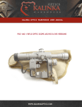
1
KALINKA OPTICS WAREHOUSE USER MANUAL
PO2.8X18 (KASHTAN 1P78)
TACTICAL COMBAT RIFLE SCOPE
WWW.KALINKAOPTICS.COM
PO2.8X18 (KASHTAN 1P78)
TACTICAL COMBAT RIFLE SCOPE
TABLE OF CONTENTS
OVERVIEW
3
INTRODUCTION
3
GENERAL DESCRIPTION
3
TECHNICAL SPECIFICATIONS
6
DELIVERY SET
6
FUNCTIONAL CAPABILITIES
7
SYSTEM COMPONENTS
7
DESIGN AND OPERATION
7
SETTING UP
8
MOUNTING THE SCOPE
8
CLAMP ADJUSTMENT
9
ZEROING THE SCOPE
10
SAFETY AND MAINTENANCE REQUIREMENTS
14
SAFETY PRECAUTIONS AND STORAGE REQUIREMENTS
14
CLEANING
14
WARRANTY
©2013 KalinkaOptics Inc.
www.kalinkaoptics.com
15
2
OVERVIEW
INTRODUCTION
Thank you for choosing the PO2.8x18 "KASHTAN" rifle scope at Kalinka Optics! We are confident that the optic you have
chosen will live up to your highest expectations.
Please, read this instruction manual carefully before using the scope. This manual will guide you through the steps to
properly install, zero and maintain your optic for optimal performance. It also gives explicit technical information on
construction and operating characteristics of this device.
Should you have questions that have not been addressed in this manual please contact us at [email protected]. We
will be happy to assist you.
GENERAL DESCRIPTION
Background
PO2.8x18 rifle scope can be also referred to as Kashtan 1P78 or Kashtan S. Kashtan 1P78. It is a military collimating scope
with a solar powered dual black/green German Post reticle, or rangefinding reticle. The scope is manufactured by
"Novosibirsk Instrument-Making Plant", Russia, also known as NPZ, and exclusively exported by Kalinka Optics.
Kashtan 1P78 is the newest collimator scope representing the leading edge of collimating technology from the NPZ factory.
Its high quality is battlefield-proven. Kashtan scopes are being used on the rifles of elite units in Russia's Ministry of Internal
Affairs (MVD): Police divisions, "Spetznaz" Special Forces, OMON, etc.
©2013 KalinkaOptics Inc.
www.kalinkaoptics.com
3
Modifications
Kashtan 1P78 is available in several versions that differ from one another by the mount shape and the rifle models they best
fit for.
Name
Overall Dimensions
Type of Weapon
Kashtan S
200x90x173 mm
AK/"Saiga" with a mounting side rail
at 290mm from the back plate
(see Figure 1)
Kashtan S2
190x90x173 mm
AK/"Saiga" with a mounting side rail
at 270mm from the back plate
(see Figure 1)
Kashtan S3
274x90x173 mm
AK/"Saiga" with a mounting side rail
at 365mm from the back plate
(see Figure 1)
Kashtan P
180x90x110 mm
Any rifle equipped with a regular
Picatinny top rail
Picture
Figure 1. Kashtan on Saiga
©2013 KalinkaOptics Inc.
www.kalinkaoptics.com
4
Main features
The clamp will fit any rifle with a standard 14 mm dovetail side optic rail, except for Kashtan P, which goes onto a Picatinny
rifle top rail. Before attempting to mount the scope make sure that your rifle has the correct side rail as it is crucial for proper
function of the scope. A side rail may not be preinstalled on the rifle. In this case a rail of the right type can be ordered at
www.kalinkaoptics.com.
Working conditions. The scope can be used in a variety of climatic conditions with temperatures ranging from -40°C to
+50°C (-40°F to +122°F) and relative humidity of up to 98%. The scope is also sealed against sand and dust as well as filled
with Nitrogen to prevent fogging.
The scope reticle is available in two versions. The first one is well known German Post also used in Rakurs scopes (Figure
2a). It not only fills the role of the traditional CQB (Close Quarters Battle) short range/fast acquisition sight, but can also be
used for longer range combat shooting.
Figure 2a
Figure 2b
The second version (Figure 2b) has rangefinding and BDC (Bullet Drop Compensation) features. The aiming chevrons are
designed to adjust for bullet drop of AK caliber at up to 700 meters, considering that the scope is zeroed at 100 meters. The
top chevron introduces no BDC and is used for aiming at ranges up to 400 meters. The dot below is used for 500 meters.
Second and third chevrons are used for BDC at distances of 600 and 700 meters accordingly.
Rangefinding capabilities are provided by the vertical bars (highlighted in green on Figure 2c). The bars and gaps between
them are sized up in Mils and can be used for range estimation.
Figure 2c
Optics. Its fully coated prismatic lens system provides a remarkable, high contrast, wide angle field of view allowing for fast
acquisition of moving and spaced targets. You have an unlimited field of view and maximum ability to register incoming
targets.
The special protective lens coatings protect the scope from scratching and fouling in the extreme battlefield conditions where
it was designed to operate. A light-dividing mechanical and coating system produces exceptional dual visualization of the
target and reticle at the same time so you see both in high resolution for better targeting.
Ballistic adjustment is carried out with the windage and elevation turrets covered with protective caps. The scope has very
accurate windage/elevation adjustments in small increments: every turret' click moves MPI (Mean Point of Impact) by 3 cm at
100 m.
©2013 KalinkaOptics Inc.
www.kalinkaoptics.com
5
TECHNICAL SPECIFICATIONS
Magnification
2.8±0.14
Objective Aperture
18 mm
Field of View
13
Field of View at 1000 m
300 m
Eye Relief
32 mm
Eye Relief Diameter
6 mm
Windage
1 MOA/click
Elevation
1 MOA/click
Reticle Style
Modified German Post
Rangefinding Capability
Yes
Illuminated Reticle
Green
Red Dot Size
No
Nitrogen Purged
Yes
Mount Type
AK, AKM, Saiga, SLR
Waterproof
Yes
Color
Grey
Tube Diameter
No
Temperature
-40 to +50 C
Power Source
Solar
o
o
Overall Dimensions
Kashtan S
200x90x173 mm
Kashtan S2
190x90x173 mm
Kashtan S3
274x90x173 mm
Kashtan P
180x90x110 mm
Item Weight*
1.3 pounds
*Slightly varies depending on the model
DELIVERY SET
Optical scope with a metal flip up objective cover – 1
Rubber eyepiece attached to the scope – 1
Protective mounted scope cover – 1
Soft carry case – 1
Lens cleaning cloth – 1
Screwdriver/spanner (Figure 3) – 1
Service Manual – 1
©2013 KalinkaOptics Inc.
www.kalinkaoptics.com
Figure 3. Screwdriver/spanner
6
FUNCTIONAL CAPABILITIES
SYSTEM COMPONENTS
1.
Flip up objective protective cover
2.
Elevation turret cap
3.
Body
4.
Eyepiece clamp
5.
Rubber eyepiece
6.
Objective aperture
7.
Latching lever
8.
Adjustment screw
9.
Latch
10. Mount
Figure 4
DESIGN AND OPERATION
The scope consists of the objective (6), prism erecting system, reticle, elevation and windage adjustment mechanisms, light
source and ocular with a rubber eyepiece (5) attached to it. These parts are integrated into the scope's body (2) as it is
shown on Figure 4.
The mount (10) with a side mounting seat of dovetail type is fastened to the lower part of the body. It is designed for
mounting the scope on "Saiga" and other AK-type rifles.
Rubber eyepiece (5) is fastened on the ocular with the clamp (4) to provide proper eye relief, comfortable aiming, and safe
usage of the scope during firing.
o
The objective cover (1) can be flipped up to 105 . It can be turned around the scope's optical axis and fixed in different
positions for protecting the objective lens from lateral sun rays and other bright light sources, which makes aiming more
comfortable.
Elevation and windage adjustment turrets covered with threaded caps (Figure 5) are intended for zeroing the scope. They
can be set in discrete fixed positions, each click shifting the aiming mark by 1 MOA.
©2013 KalinkaOptics Inc.
www.kalinkaoptics.com
7
Figure 5
SETTING UP
MOUNTING THE SCOPE
Before mounting the scope make sure that you have an AK style side optic rail installed on your rifle.
If you are not careful to ensure you have the correct rail model for your scope it is possible to mount the scope on a wrong rail like SVD style,
for example. While it may seem to ‘fit’, you will encounter problems such as too much or not enough of eye relief, the scope won't hold its
"zero" if removed, etc. Finally, shooting with an improperly installed scope may cause damage due to recoil.
1.
Mount
2.
Clamp
3.
Adjustment screw
4.
Retaining clip
5.
Latching lever
Figure 6
The scope has a nondetachable mount (1) that will fit a regular 14 mm dovetail AK style side rail placed on the left side of your rifle (see
Figure 6). The mounting procedure consists of the following steps:
1. Loosen the clamp (2) by turning the latching lever (5) clockwise up to its extreme outer position. When in home position the lever is firmly
locked to avoid occasional detachment of the scope. To unlock the latching lever push it down and then turn it aside.
2. Slide the scope onto your side rail moving it forward towards the barrel until it reaches the forward position. Then turn the lever
counterclockwise to tighten the clamp (Figure 7). Make sure that the lever is latched into its initial home position and won't come off
©2013 KalinkaOptics Inc.
www.kalinkaoptics.com
8
spontaneously.
Figure 7
CLAMP ADJUSTMENT
Grip of the clamp can be adjusted if it appears to be too tight or too loose. Complete the following steps for the clamp
adjustment:
1. Turn the latching lever (5) clockwise to release the clamp and remove the scope from the rifle side rail. Place the scope
upside down to obtain easy access to the latching system of the mount.
2. Locate the retaining clip (4) that is holding the lever onto the scope. Using a flat screw driver, turn the adjustment screw (3) a little to
release the clip.
3. Place a flat screwdriver blade on the edge of the retaining clip and rotate it out of its indentation.
Figure 8
©2013 KalinkaOptics Inc.
www.kalinkaoptics.com
9
o
4. Once the retaining clip is placed at 90 to the latching lever, you can easily slide it off of the center shaft of the lever and
remove it to release the latching lever (Figure 8).
5. Once the clip is removed, you can disengage the lever from its tooth gear on the center shaft.
6. Slide the scope onto your side rail and then reposition the lever so that you have a nice tight fit (Figure 9). Be careful not to
over-tighten!
Figure 9
Once the proper tension is obtained, you can fix the lever in the right position replacing the retaining clip by inserting the
center shaft into the large hole in the clip. Then simply slide the clip back into the indentation and tighten back the adjustment
screw if necessary.
After the reassembling is complete you may want to try the fit. Make sure that the scope will slide onto the side rail easily,
and will also tighten up securely. There should be a moderate amount of tension on the lever when it is about 85% closed,
and it should take mild pressure to lock it completely. Do not over-tighten! Repeat the procedure to adjust the grip if needed.
ZEROING THE SCOPE
General
Zeroing is the process of aligning the point of aim with the point of impact, so that the two become one (see Figure 10).
©2013 KalinkaOptics Inc.
www.kalinkaoptics.com
10
Figure 10
Point of aim: The spot where you are aiming at, denoted as the spot where the crosshairs on your reticle intersect.
Point of impact: The spot where your bullet actually impacts the target.
Thus, all we are basically doing is making sure that the bullet actually goes where we put the aiming mark, i.e. the chevron in the middle of
the reticle.
We have to keep in mind that the trajectory of a bullet is more or less an arc rather than a straight line. When a bullet runs out of steam, it
falls to the ground. This part seems fairly intuitive, but most people fail to realize that the moment the bullet leaves the barrel it succumbs to
gravity and begins a downward trajectory. No matter how high powered the cartridge is, gravity always wins.
This fact brings us to conclusion that we must zero the rifle at a certain range, and since gravity affects the bullet, the rifle is only zeroed to
that range – any other range will require corrective input on the scope by adjusting the elevation turret. That is why first of all we should
define the preferred range to zero a rifle (and therefore zero the scope) at. Most military units zero weapons at 300 meters, but that is
impractical for civilians as there aren’t always shooting ranges with that kind of distance available.
In any case we have to follow the rule:
Zero at the range you intend to engage targets at
The safe bet for most shooters that are shooting .308 (7,62×51mm), .30-06 (7,62×63mm) or similar caliber is to zero at 100 meters, as this is
an easily obtainable distance. These cartridges shoot relatively flat out to 500 yards, so there isn’t much if any adjustments that need to be
made inside those distances.
Zeroing the scope at the range
Since the long-range zeroing procedure involves real shooting it is to be carried out outdoors with as little wind effects as possible. This
method can be used with much longer shooting distances like 200 or 300 meters. Nevertheless, you may want to choose a range that seems
most appropriate for your perspective targets, which is usually 100 meters or less. Besides, since magnification of the scope is relatively
small, zeroing at shorter distances appears more reasonable.
1. Mount the scope to the rifle. Make sure it is firmly set on the side rail. It’s easy to impart errors into the scope by mounting it slightly
crooked.
2. Position the gun on shooting bags or in a gun vise, or use the gun’s bipod. In other words, shooting should be carried out in conditions that
provide the best stability.
3. Load the rifle, place the aiming mark on the target, without moving the rifle fire 3-5 shots, which would be enough to determine the mean
point of impact (MPI). While shooting make sure that the mark is fixed on the target and doesn't deviate from shot to shot.
4. Note where the shots went with respect to target. Were they high? Were they low? The best way to check this is by actually walking up to
the target and looking at it. Determine the MPI and mark it on the target for better identification (Figure 11). If the scope is zeroed the MPI
has to coincide with the point of aim. If the two points diverge by more than 5 cm the following steps should be made.
5. Carefully look through the scope and place the aiming mark on the center of the target (Figure 11).
©2013 KalinkaOptics Inc.
www.kalinkaoptics.com
11
Figure 11
6. Remove the protective caps of the windage and elevation turrets and get the spanner handy for adjustment procedures.
7. While holding the rifle steady, turn the windage and elevation turrets with the spanner (Figure 12) so that the aiming chevron mark aligns
with the MPI that you marked on the target. Arrows and letters on the turrets' black top rim show the direction of trajectory correction:
U - UP / D - DOWN
L - LEFT / R - RIGHT
Turning a turret by 1 click shifts the MPI by 1 MOA, i.e. 3 cm at the range of 100 m.
Figure 12
8. Fire another round, aiming through the scope for the center of the target. Your shot should be dead on. If not, repeat steps 5 and 7.
7. After the scope is zeroed install the protective caps back to the adjustment turrets.
9. Now that your rifle and scope are zeroed for the chosen range, you may want to fire off a few more shots to make sure that the settings
are correct.
Zeroing with a laser bore sight
Alternatively, you can also zero a scope with a laser bore sight. This method is rather convenient and accurate. It also
saves your ammo. However, one can never be sure that a scope is precisely zeroed without checking it by making a few
shots.
©2013 KalinkaOptics Inc.
www.kalinkaoptics.com
12
A good laser bore sight will put you on paper. This easy-to-use
product helps the sighting process go much smoother and can
get a shooter within four inches of the bull's-eye at 100 yards.
Bore sights generally come in two types: the ones that go into
the chamber like a real cartridge and the ones that are to be
attached to the front of the barrel (Figure 13). In any case this
device is needed to produce a laser beam coming straight out of
the barrel.
Thus, you can conveniently see through the scope both the laser
spot covering the target and the aiming mark. Adjusting the
scope, you can make the two points overlap without even taking
your eye off the ocular.
Figure 13
Despite all advantages, bore sight zeroing has an obvious drawback stipulated by divergence of the strait laser beam and the declining real
bullet trajectory (see Figure 14). Therefore, the more range we have the less accuracy we get. That is the reason why bore sights won't work
well at relatively long distances. Most manuals recommend aiming at a target that is 25-50 meters away.
Figure 14
No matter how good your bore sighting is the final sight-in will be shooting the firearm. If you want to achieve a maximum of accuracy you
should zero your optic scope with live ammunition as described above.
Final notes
One should keep in mind that aside from precise zeroing the scope, there are other factors affecting accuracy of shooting. In addition to
weather conditions that may influence the trajectory, your zero changes any time you:
Use a sufficiently different load of ammunition than you zeroed with
Use a heavier or lighter bullet than the bullet you zeroed with
Hold the rifle differently or have a different check weld than you originally zeroed with
Have a different eye relief than you originally zeroed with
Shoot at a different range than you originally zeroed with
©2013 KalinkaOptics Inc.
www.kalinkaoptics.com
13
SAFETY AND MAINTENANCE
REQUIREMENTS
SAFETY PRECAUTIONS AND STORAGE REQUIREMENTS
Before using the scope make sure that the mount matches the side rail installed on your rifle. The scope must be
securely fastened to the side rail. Shooting with an improperly installed scope may cause damage due to due to
recoil. See the mounting instructions above if the clamp appears too loose.
Never disassemble the scope.
Protect the scope from shocks and other mechanical damages to exclude destruction of delicate optical lenses and
the light element.
Do not touch the optical surfaces with your hands.
All moving assemblies are permanently lubricated and do not require additional lubrication.
After using the scope in wet conditions wipe it with dry soft cloth and live it to dry out at a temperature not exceeding
112 F°.
Keep the turret caps in place at all times when you are not using the adjustment system. These caps are intended to
keep moisture, dust and dirt out of the mechanical system.
Close the objective lens with the flip-up cover (see Figure 4) during breaks in operation. Protect optical lenses from
scratches during operation and storage.
Store the device in a bag.
o
Optimal storage conditions are at temperatures ranging from 5 to 50 C and relative humidity not exceeding 85%
Avoid storing the scope in hot places, such as the passenger compartment of a vehicle on a hot day. High
temperature could adversely affect the lubricants and sealants.
Never leave the scope where direct sunlight can enter either the objective or the ocular lens. Damage may result
from the concentration of the sun’s rays, commonly known as burning glass effect.
CLEANING
Coarse dirt/debris must be removed from the lens surface. Failure to remove grit before final cleaning is sure to damage lens
coatings.
Position the lens so particles will fall away and then use a soft brush to gently whisk away the debris, while blowing on the
lens to dislodge the particles. For heavy dirt, like dried mud, use a spray of clean water or lens cleaning fluid to remove the
dirt.
After the dirt is removed, use a lens cloth or soft cotton cloth to whisk away the remaining smudges and debris. Lightly
breathing on the lens surface will moisten the surface and aid this process. Never rub a lens — gently whisk it with slight
pressure. Avoid having only one thickness of cloth between your finger tip and the surface. Bunch up the cloth loosely so it
absorbs the pressure of the cleaning. Rotate the cloth around the lens surface, working from center to edge of lens.
Only occasional cleaning of the outside of the scope is required. You may use a soft cloth to wipe dirt or fingerprints off the
scope body.
©2013 KalinkaOptics Inc.
www.kalinkaoptics.com
14
WARRANTY
The scope meets or exceeds the quality standards set forth by the manufacturer and its technical specifications match those listed in this
manual.
Kalinka Optics Warehouse® offers its Unbeatable Full 12-month Factory Warranty on all products sold against defects in workmanship and
materials for one year from date of purchase. Absolutely no returns or warranty claims will be processed without a Return Authorization
Number, see the site for details. If maintenance or feasible and justifiable repairs have to be done upon expiration of the warranty period, all
costs related to these services are the responsibility of the customer.
Thanks for Shopping with US!
For further questions or additional information please contact:
KalinkaOptics Inc.
406 S Marine Blvd. Suite #2
Jacksonville, NC 28540, USA
E-mail: [email protected]
Phone: +1 (910) 989-0109
Fax: +1 (888) 817-8097
©2013 KalinkaOptics Inc.
www.kalinkaoptics.com
15