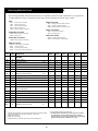
1
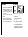
ONL843NSATS
For Models: NL843N2, NL843NW2, and NL843N3
OPERATOR’S MANUAL
Marine Generators | Marine Diesel Engines | Land-Based Generators
As of January 2008, U.S. EPA regulations require the
application of a permanently applied label near the fuel tank
fill port for diesel driven equipment. This label is to state:
LOW OR ULTRA LOW SULFUR FUEL ONLY
Northern Lights is providing this label for application to the
fuel inlet of the fuel supply tank for each engine or generator
set. This is to be applied by the installer of the engine or gen
set, or by the manufacturer of the equipment that the engine
or gen set is installed in. The location of the label must be
in clear site of personnel that refill the supply tank.
Note: Starting in 2011, the label will state:
ULTRA LOW SULFUR ONLY.
— CALIFORNIA —
Proposition 65 Warning:
Diesel engine exhaust and some of its constituents are known to the State of California to cause
cancer, birth defects, and other reproductive harm.
Northern Lights
4420 14th Avenue N.W.
Seattle, WA 98107
Tel: (206) 789-3880
Fax: (206) 782-5455
Copyright ©2009 Northern Lights, Inc.
All rights reserved. Northern Lights™, and
the Northern Lights logo are trademarks of
Northern Lights, Inc.
Printed in U.S.A.
PART NO.: ONL843NSATS 10/09
OPERATOR'S MANUAL
for Models
NL843N2, NL843NW2, and NL843NW3
Read this operator's manual thoroughly before starting to operate your equipment.
This manual contains information you will need to run and service your new unit.
Table of Contents
Introduction ................................................. 4
Models Included............................................... 4
Model Numbers................................................ 4
Serial Numbers................................................. 4
Servicing (continued)
V-Belts.......................................................... 13
Valve Clearances............................................ 13
Fuels - General............................................... 14
Fuel Filters..................................................... 14
Bleeding the Fuel System................................ 15
Injector Service....................................... 16 - 17
Injection Pump............................................... 17
Cooling System - General................................ 17
Cooling System Flushing................................ 18
Generator Ends............................................... 18
Electrical System - General............................. 18
Glow Plugs.................................................... 18
Booster Batteries............................................ 19
Battery Care................................................... 19
Winterizing / Out-of-Service............................ 19
Warranty . ..................................................... 5
Safety Rules.................................................. 5
Component Locations
NL843NW2 Industrial Generator....................... 6
CONTROL Panels
Northern Lights Generator Sets.......................... 7
Operating Procedures
Break-in Period................................................ 8
Before Starting................................................. 8
Starting............................................................ 8
Operating......................................................... 8
Stopping.......................................................... 8
Shutdowns and Alarms...................................... 9
Spare Parts....................................................... 9
Troubleshooting
Electrical....................................................... 20
Engine.................................................... 21 - 23
Wiring DiagramS
AC Electrical.......................................... 24 - 25
DC Electrical.......................................... 26 - 27
Servicing Schedule Chart..................... 10
Servicing
Lubrication - General...................................... 12
Checking Oil.................................................. 12
Oil Changes................................................... 12
Changing Oil Filter......................................... 12
Air Filter........................................................ 13
Proprietary Information
This publication is the property of Northern Lights, Inc.
It may not be reproduced in whole or in part without the written permission of Northern Lights, Inc.
© Northern Lights, Inc. All rights reserved. Litho U.S.A. Publication number ONL843NSATS 10/09
ONL843NSATS 10/09
Introduction
As operator, it is your obligation to learn about your
equipment and its proper maintenance. This is not a
comprehensive technical service manual. Nor will it
make the reader into an expert mechanic. Its aim is to
aid you in maintaining your unit properly.
Servicing of generator sets presents unique problems.
Failures often occur in remote areas far from competent
assistance. Generators are taxed far more severely than
auto or truck engines; therefore, maintenance schedules
must be adhered to more strictly.
Failures can begin with minor problems that are overlooked and become amplified when not corrected during
routine maintenance.
Unit Identification
ModelS INCLUDED
This manual covers the operating instructions for:
NL843N2, NL843NW2, and NL843NW3 industrial generator sets
Fill in the model number of your unit in the blank space provided.
This will give you a reference whenever service or maintenance is required: My Northern Lights generator set model number is:
Model Numbers
Model numbers give the unit's application, block model, aspiration, and RPM:
NL
Northern Lights industrial generator set
NL843NW2
=
N, W
843
+
Model number of engine block
Bore
Cylinders
84 mm
3
Northern Lights industrial diesel generator set
with an 843N engine and a PX-312K2
generator end.
NL843N2
+
=
N: N engine
W: New winding
Northern Lights industrial diesel generator
set with an 843N engine and a BCI 164
generator end.
Serial Numbers
Your set has three serial numbers: 1 an engine number stamped
on the block, 2 a generator plate, and 3 a generator set plate.
Use the serial number on the generator set plate when ordering parts
or in correspondence. The generator set plate is found on the service
side of the generator and resembles the drawing in Figure 1.
Figure 1: Generator set serial number plate.
ONL843NSATS 10/09
Warranty
NOTE: If the warranty is to apply, the servicing
instructions outlined in this manual must be
followed. If further information is needed, please
contact an authorized dealer or the factory.
A warranty registration certificate is supplied
with your set. It entitles the original purchaser of our
equipment to a warranty covering material
or assembly faults. The extent of coverage is described
in the Limited Warranty Statement. We recommend
that you study the statement carefully.
Safety Rules
CAUTION: Accident reports show that careless use of engines causes a high percentage of accidents.
You can avoid accidents by observing these safety rules. Study these rules carefully and enforce them on the job.
• Never leave engine without proper security.
• Keep your hands, feet, hair and clothing away from
power-driven parts.
• Turn the coolant tank cap slowly to relieve pressure
before removing. Add coolant only when the engine
is stopped and cool.
• Check for any loose electrical connections or faulty
wiring.
• Mount a fire extinguisher near engine.
• Engines should be operated only by knowledgeable,
qualified personnel.
• Always disconnect the battery ground strap before
making adjustments.
• Look completely around engine to make sure that
everything is clear before starting.
• Operate engines in properly ventilated areas.
• Do not operate an engine that isn't in proper
working order. If an unsafe operating condition is
noted, tag the set and control panel so others will
also know about the problem.
• Keep trash and other objects away from engine.
• Escaping fluids under pressure can penetrate your
skin. Use a piece of cardboard or wood, not your
hands, to search for leaks.
• Provide first aid kits.
• Avoid wearing loose clothing without a belt when
working around engines.
• Do not oil or grease engine while it is running.
• Use caution in handling fuel. Never refuel a hot
or running engine. Do not smoke while filling fuel
tank or servicing fuel system.
CAUTION: This symbol is used throughout
this book to alert you to possible danger areas.
Please take special notice of these sections.
ONL843NSATS 10/09
Industrial Generator Component Locations
4
3
5
7
6
8
9
10
11
2
12
1
13
22
20 19 18 17 16
21
23
15
14
24
28
26
25
29
27
Figure 2A
and 2B:
NL843NW2
1. Control Panel Plug-in
2.Generator Plate
3.Generator Junction Box
4. DC Circuit Breaker
5.Air Filter
6.Air Filter Pre-cleaner
22
7. Oil Fill
8. Fuel Injector
9. Oil Pressure Switch
10. Coolant Fill
11. Injection Pump
12. Shutdown Solenoid
13.
14.
15.
16.
17.
18.
Fuel Filter/ Water
Separator
Fuel Inlet Line
Fuel Return Line
Oil Dipstick
Block Drain
Oil Drain Valve
ONL843NSATS 10/09
19.
20.
21.
22.
23.
24.
Oil Filter
Fuel Lift Pump
Magnetic Pick-up
Secondary Fuel Filter
Coolant Temp. Switch
Exhaust Outlet
25.
26.
27.
28.
29.
Starter
DC Alternator
Detachable Supply &
Return Valves
Fuel Filter Neck
Fuel Gauge Sender
S-1A Control Panel
8
2
1
1. Autostart/ stop module
3
7
Automatically pre-heats, starts, and monitors the
engine for overcrank, overspeed, high coolant
temperature, and low oil pressure. Annunciates run
and fault conditions via unit mounted LEDs. Also
monitors mag pick-up signal. If signal is lost, the
engine will shut down and the overcrank and overspeed LEDs will turn on.
2. ENGINE CONTROL SWITCH
Toggle switch, turns engine off or on.
3.HOUR METER
Keeps track of engine running time.
4. Master battery switch
6
5
4
On/ off switch disconnects batteries from engine
controls.
5.Battle short switch
Figure 3-a: S-1A Control Panel
Bypasses safety shutdowns. Does not bypass mag-
netic pick-up shut down or prevent user from shutting the engine down via the engine control switch
(#2) or the emergency stop switch (#6).
6. Emergency stop
Easily accessible button to turn the engine off quickly.
9
7. Switch to activate fuel gauge
Activates fuel gauge when the engine is not running.
8.Fuel level gauge
Shows fuel level.
9.auxiliary dc power supply
Extra plug-in for DC power.
Figure 3-b: Auxiliary DC Power Supply (NATO Connector)
ONL843NSATS 10/09
Operating Procedures
BREAK-IN PERIOD
starting
1. The first 100 hours on a new or reconditioned
engine are critical to its life and performance.
2. Frequently check the engine temperature and oil
pressure.
3. Oil consumption is greater during break-in as
piston rings take time to seat.
4. Break-In Oil Changes: Change engine oil and
filter at 50 hours. Change oil and filter again at
100 hours (consult Lubricants section for oil
recommendation).
1. Turn the toggle switch to Start/ Run position. The
engine will take 15 to 20 seconds to start cranking
(with glow plugs).
2. If the unit automatically shuts down (and the
problem fixed) the toggle switch has to be placed in
the Off/ Reset position before starting again.
Operating
1. If the generator shuts down automatically,
investigate possible reasons; high temperature, low
oil pressure, etc... then reset and restart.
2. Let the unit run unloaded for a three to five minute
warm-up period.
3. Apply electrical load.
Operating Instructions:
Maintain at least a 75% load on your generator
set for the first 100 hours. If this is not possible,
maintain no less than a 50% load to ensure proper
seating of the piston rings. Vary the load to help
seat the rings.
stopping
1. Remove electrical load from the generator set.
2. Run the engine for a 3 to 5 minute cool down
period.
3. Turn the Engine Control switch to the Off/ Reset
position.
Before Starting
1. Check the water level by removing the pressure
cap from the radiator. In order to give the cooling
water an opportunity to expand, the level should
be about 1 in. (2.5 cm) below the filler cap sealing
surface when the engine is cold.
SHUTDOWNS
CAUTION: Use protective clothing and open
the filler cap carefully when the engine is warm
to prevent burns.
1. Your unit is fitted with a system to protect it from
high water temperature or low oil pressure.
a. Generator sets have shutdown systems to stop the engine. They have no warning horns.
2. Do the following when your warning or shutdown
system is activated:
a. Use the Trouble Shooting Guide on page 20 to
isolate the cause of the overheat.
2. Check the oil level in the crankcase with the
dipstick. The oil level must be in the waffled area on
the stick. Never allow the level to go below this area.
Always add the same viscosity of oil as is already in
the crankcase.
3. Check the fuel tank level and open any fuel valves.
4. NOTE: The battery switch must always be kept
ON while the engine is running. If the switch is
turned OFF while the engine is running, the
battery charging regulator could be ruined.
ONL843NSATS 10/09
Operating Procedures
CAUTION: Do not remove the water fill
cap of an overheated engine. Escaping high
temperature steam can cause severe burns.
Allow the engine to cool and then remove the
cap slowly using protective clothing.
3.
d. Make repairs. Repeat troubleshooting.
If your set is operating a long distance from a
servicing dealer, add the following:
a. Complete set of injectors
b. Copper washers for injector change
c. Complete set of glow plugs
d. Fuel lift pump
3. If shutdown is activated and the temperature does
not appear to be outside the normal temperature
range:
a. Check the engine crankcase oil level.
b. If the oil level is low, fill with recommended
lubricating oil and restart. Watch the oil pressure
gauge carefully and shut off the engine if it does
not show a normal reading (20-60 PSI) after a
few seconds of operation.
c. If the oil level is normal, DO NOT restart the
engine. Call your dealer for assistance.
SPARE PARTS
1. Northern Lights recommends that you keep the
following spare parts on hand for field service. The
parts are available from your local Northern Lights
dealer.
2.
All owners should have the following spares:
a. Primary and secondary fuel filter elements
b. Oil filters
c. Air filter
d. Alternator belt
e. Thermostat and gaskets
f. Glow plug
g. Injector and washer
ONL843NSATS 10/09
Servicing Schedule Chart
The Servicing Schedule Chart below shows the service schedule required for proper maintenance of your generator
set. More detailed coverage of each Service Point (SP) is listed on the page noted in the ‘page’ column.
DAILY:
SP1
SP5
SP7
SP13
SP18
EVERY 500 HOURS:
SP8 Change primary fuel filter element
SP9 Change secondary fuel filter
SP22 Inspect condition of exhaust system
Check oil level in engine
Check V-belt tension
Check primary fuel filter
Check coolant level
Check electrolyte in batteries
EVERY 1000 HOURS:
SP6 Check valve clearances
SP11 Check injectors
AFTER FIRST 50 HOURS:
SP2/3 Change engine oil and filter
SP6 Adjust valves
EVERY 2500 HOURS:
SP12 Check fuel injection pump
SP14 Check and flush cooling system
AFTER FIRST 100 HOURS:
SP2/3 Change engine oil and filter
EVERY 250 HOURS:
SP2/3 Change engine oil and filter
SP4
Check air cleaner
SP15 Check and clean radiator
SP19 Check state of charge of batteries
SERVICE
50
250
500
1000
2500
POINT PAGE OPERATIONDAILYHoursHoursHoursHoursHours
ENGINE:
SP1
12
Check oil level
SP2
12
Change engine oil
1) 5)
SP3
12
Change lube oil filters
1) 5)
•
•
•
SP4
13
Check air cleaner, change element @ 1000 hrs. 1) 4)
SP5
13
Check V-belt tension
SP6
13
Check valve clearances
•
1) 2) •
•
•
FUEL SYSTEM:
SP7
14
Check primary filter (Racor)
2) 3)
SP8
14
Change primary filter element (Racor)
2) 3)
SP9
14
Change secondary fuel filter
1) 3)
SP10
15
Bleed the fuel system
SP11
17
Check injectors
SP12
17
Check fuel injection pump
•
•
•
•
3)
1) 3) 6) 7)
•
7)
COOLING SYSTEM:
SP13
17
Check coolant level
SP14
18
Check and flush cooling system
4)
SP15
18
Check and clean radiator 4)
ELECTRICAL SYSTEM:
SP18
19
Check electrolyte level in batteries
SP19
19
Check condition of batteries with hydrometer
OUT OF SERVICE:
SP21
Winterizing or out-of-service
19
•
•
1) 4)
•
•
•
•
3)
1) Perform all maintenance once a year even if hour level has not been reached.
2) Consult manufacturer's maintenance schedule, note on chart.
3) Whenever necessary.
4) More often if necessary.
5) After first 50 hours, then after 100 hours, then at every 250 hours.
6) Clean injection nozzles every 1500 hours.
7) For EPA emission standards fuel nozzle needs to be cleaned
every 1500 hours, the fuel nozzle and fuel pump need to be
cleaned, adjusted, or repaired every 3000 hours, and the quality
guarantee for these parts is 1500 hours or 2 years.
ONL843NSATS 10/09
10
Service Record Notes
ONL843NSATS 10/09
11
Servicing
LUBRICATION - GENERAL
SP2. OIL CHANGES
1. Use only clean, high quality lubricants stored in
clean containers in a protected area.
2. These lubricants are acceptable:
a. API Service CC/CD/CE single viscosity oils.
b. API Service CC/CD/SF multi-viscosity oils.
3. Use the proper weight oil for your average operation temperature.
1. The set is delivered with special break-in oil.
Change the engine oil and oil filter after 50 hours
of operation. Use Service CC 30 weight oil during
the first 100 hours.
2. Change the oil and filter again at 100 hours using the
oil recommended in the above diagram. After this,
change oil and filter every 250 hours.
3. During intermittent cold weather operation, change
oil every 100 hours or six weeks, whichever comes
first.
4. Change oil at the end of each season and the
beginning of each season.
5. Change oil when engine is warm.
6. Dispose of waste oil in an approved manner.
7. Never use a flushing oil.
8. Loosen the clamp on the oil change tube. Remove
cap. Drain oil. Replace the cap and tube.
9. Refill engine with recommended oil for the season.
10.Engine capacity with new oil filter is:
NL843NW2 and NL843N2 – 1.6 gallons
(6 liters)
Air
Single
Multi TemperatureViscosityViscosity
Above 32°F
(0°C)
SAE 30W
SAE 15-40W
-10 to 32°F
(-23 to 0°C)
SAE 10W
SAE 10-30W
Below -10°F
(-23°C)
SAE 5W
SAE 5-20W
Figure 4: Lube Oils
4. Some increase in oil consumption may be
expected when SAE 5W and SAE 5-20W oils are
used. Check oil level frequently.
5. Never put additives or flushing oil in crankcase.
SP1. Checking oil level
1. Check the oil level in the crankcase with the dipstick. The oil level must be in the waffled area
on the stick. Never allow the level to go below
this area. Follow the lubrication recommendations
above.
SP3. CHANGING lube OIL FILTER
1. Change the lube oil filter every 250 hours.
2. Use a filter wrench to remove old filter. Dispose of
filter in approved manner.
3. Make sure the gasket from the old filter is removed
and discarded. Clean mount face.
4. Spread a thin film of engine oil on the rubber gasket
on the new filter and screw it on nipple until gasket
meets the sealing surface.
5. Using hands only – no wrench – tighten filter
one-half turn farther. Overtightening can do
damage to filter housing.
6. Fill engine with recommended oil. Start engine and
check for leakage. Stop engine, wait 3 minutes, and
check oil level. Add additional oil if necessary.
7. Oil filter part number is:
NL843N2 & NW2 – #24-03100
ONL843NSATS 10/09
12
Servicing
SP4. AIR cleaner
1.
2.
Inspect air cleaner every 250 hours. In dusty
conditions, check more often.
Replace if necessary. Part number is:
NL843NW2 & N2 (element only) – #24-27302
3. NOTE: Make absolutely sure no impurities enter
the engine while changing the element. Do not
run the engine with the air cleaner removed.
Figure 6: Valve Adjustment
SP6. VALVE CLEARANCES
SP5. V-BELTS
1. Check the tension and wear on the V-belt daily,
with the engine shut off.
2. Use your thumb to press on the belt at the midpoint
between the crankshaft and alternator pulleys. The
tension is correct if the belt can be depressed about
3/16 in. (5 mm). Fan belt slackness should be about
3/16 in. (5 mm).
3. To adjust the belt tension loosen the alternator
adjusting plate bolt and the alternator mounting bolt.
Pivot the alternator at the mounting bolt as needed.
4. Tighten the mounting bolt and the adjusting bolt.
5. Re-start the engine and operate engine at low speed
and recheck the belt tension, after stopping the
engine.
1. Adjust valve clearance after first 50 hours of
operation and every 1000 hours thereafter.
2. Valve adjustments should be done after the cylinder
head bolts have been re-tightened. Engine should be
cold and NOT running.
3. Watch the valves while turning the engine over by
hand. Turn until the inlet valve starts to open and the
exhaust valve starts to close (the valves are
rocking). Then turn the crankshaft one more full
turn and adjust the clearance on both valves for this
cylinder. Align the top mark of the crank pulley with
the TOP mark of the timing gear case.
4. Loosen the lock nut and adjust the clearance between
the rocker arm and valve guide of both the intake
and exhaust valves with the adjustment screw (Figure
6). Clearance on both intake and exhaust valves
should be 0.008 in. (0.2 mm).
5. Repeat steps 3 and 4 for each cylinder. Each set of
valves must be adjusted individually.
6. Replace the rocker arm cover. Tighten cover nuts to
5 - 8 ft/lbs (0.8 - 2.3 kg/m).
Cylinder
No. 1
No. 2
No. 3
Valve
Arrangement
In
In
In
Ex
Ex
Ex
When No. 1
cyl. is at TDC
in compression
stroke
With the
crankshaft
turned by 3600
in normal
direction from
above
Figure 7: 843NW2 Valve sequence
Figure 5: Timing mark
ONL843NSATS 10/09
13
Servicing
FUELS - GENERAL
SP7-9. FUEL FILTERS
1. Use only clean, high quality fuels of the following
specifications, as defined by ASTM designation
D975 for diesel fuels:
a. Use grade no. 2 diesel at ambient temperatures
above freezing 32°F (0°C).
b. Use grade no. 1 at ambient temperatures below
freezing and for all temperatures at an altitude of above 5,500 ft. (1500 meters).
2. Use fuel having less that 1% sulphur (preferably
less that 0.5%).
3. The cetane number should be a minimum of 45.
4. DO NOT use these unsuitable grades of fuel:
a. Domestic heating oils, all types.
b. Class B engine.
c. Class D domestic fuels.
d. Class E, F, G or H industrial or marine fuels.
e. ASTM-D975-60T No. 4-D and higher number
fuels.
5. Storing fuel:
a. Keep dirt, scale, water, and other foreign matter out of fuel.
b. Avoid storing fuel for long periods of time.
c. Fill the fuel tank at the end of each day’s
operation. This will reduce condensation and
possible biological contamination.
d. If biological contamination is detected or
suspected, contact your dealer for assistance.
Primary
Fuel Filter
Part Numbers
Complete Unit:
24-50002
Element:
24-50012
Figure 8: Primary Fuel Filter (if provided by Northern Lights)
1. Your generator set may have a primary fuel filter
installed. We recommend the Racor brand of fuel
filter-water separators.
a. Check the primary fuel filter daily as
recommended by the filter manufacturer.
Empty the collection bowl as necessary.
b. Change the element as often as necessary or
every 500 hours.
c. If the bowl fills with water, change the primary
and secondary element immediately.
2. Change secondary fuel filter every 500 hours.
NOTE: The fuel filter on the engine is considered the
“secondary fuel filter.”
a. Remove the spin-on filter by turning it
counterclockwise with a filter wrench. Fill the
new cartridge with fuel and install it after
applying engine oil to gasket surface. Screw on
until the gasket surface comes into contact with
sealing surface of filter base. Then, tighten it
two-thirds of a turn by hand. Do not overtighten.
b. Secondary fuel filter cartridge part number is:
NL843N2 & NW2 – #24-52020
ONL843NSATS 10/09
14
Servicing
SP10. Bleeding the fuel system
CAUTION: Escaping diesel fuel under pressure can penetrate skin causing serious personal injury.
Before disconnecting lines be sure to relieve all pressure. Before applying pressure, be sure all connections are tight and lines, pipes and hoses are not damaged. Fuel escaping from a very small hole can be
almost invisible. Use a piece of cardboard or wood, rather than hands, to search for suspected leaks. If
injured by escaping fuel, see a doctor at once. Serious infection or reaction can develop if proper medical
treatment is not administered immediately.
Figure 9: NL843NW2 Fuel System (for illustration purposes).
1. The fuel system is self-bleeding. However, any
system may need manual bleeding when:
a. A new fuel filter is installed;
b. The engine has run out of fuel;
c. The fuel lines, injection pump or any other fuel
system component has been removed and
installed.
2. Loosen bleed bolt “A” (Figure 9) on top of the filter.
Pump hand primer “B” on fuel lift pump until pure
fuel (no bubbles) escapes from bleed bolt “A”.
Tighten bleed screw “A”.
3. Loosen bleed screw “C”. Pump hand primer “B” until
pure fuel (no bubbles) escapes. Then tighten bleed
screw “C”.
4. If the engine does not start after the above bleeding
process, loosen a fuel line at the injector while
cranking the engine with the starter motor until pure
fuel escapes. Then tighten the connection. Do each
line one-at-a-time.
5. After the engine has started, use a piece of cardboard
to look for fuel leaks.
ONL843NSATS 10/09
15
Servicing
Figures 10-17: For illustrative purposes only, may not be exact model.
Figure 10: Remove delivery line flare nuts.
Figure 14: Remove return line.
Figure 11: Remove delivery lines.
Figure 15: Unscrew injector.
Figure 12: Cover lines, inlets and injection pump outlets.
Figure 16: Remove and replace copper sealing washer.
Figure 13: Remove return line nuts.
Figure 17: Reinstall injector. Torque to proper tightness.
ONL843NSATS 10/09
16
Servicing
SP11. INJECTOR SERVICE
SP12. Injection pump
1. Injectors should be checked every 1000 hours.
Check should be made by a Northern Lights dealer
or local injection repair station.
1. Since operating conditions may vary considerably, it
is difficult to give a definite interval for checking the
injection pump. But as a rule, pump settings,
maximum speed, idle speed, and exhaust smoke
should be checked after every 2500 hours of
operation. Service of the fuel injection pump should
only be done if checks indicate pump malfunction.
2. Black smoke can be an indication of pump
malfunction. Before servicing the pump, check other
possible causes:
a. Check cleanliness of air filter.
b. Check valve clearances.
c. Clean and check injectors.
3. Any repair which involves disassembly of the
injection pump must be carried out by specially
trained mechanics with the proper tools and test
equipment.
NOTE: All warranties on the engine become null
and void if the injection pump seals are broken by
unauthorized persons.
CAUTION: Escaping diesel fuel under pressure
can have sufficient force to penetrate the skin
causing serious personal injury. If injured by
escaping diesel fuel, see a doctor at once.
2. Injector removal:
a. Clean loose dirt from around the injectors and
the fuel lines.
b. Relieve high pressure in the fuel lines by
loosening the delivery line flare nuts at each
injector (Figure 10).
c. Remove delivery lines by disconnecting from
injectors and injection pump (Figure 11). Remove
all lines as an assembly; do not remove the spacers.
Cover the ends of the lines, the injector inlets and
injection pump outlets to keep dirt out (Figure 12).
d. Remove the return line retaining bolts (Figure 13).
Remove the return line (Figure 14).
e. Unscrew and remove the injectors (Figure 15).
NOTE: Do not use pry bars to remove injectors
from cylinder head.
f. After removing the injectors, discard the copper
sealing washers from the injector hole in the head
(Figure 16). Cover holes to prevent dirt and debris
from entering the cylinders.
COOLING SYSTEM - GENERAL
CAUTION: The cooling water in the engine
reaches extremely high temperatures. You
must use extreme caution when working on
hot engines to avoid burns. Allow the engine
to cool before working on the cooling system.
Open the filler cap carefully, using protective
clothing when the engine is warm.
3. Injector installation:
a. Install a new copper sealing washer in each injector hole (Figure 16).
b. Screw in injector and tighten to 44 - 51 ft/lbs
(6 to 7 kgm) (Figure 17).
NOTE: Overtightening can damage injector.
c. Install return line using a new sealing washer below each connection. Tighten return line
retaining bolts to 22 - 30 ft/lbs.
d. Install delivery lines. Leave loose at injectors for
bleeding.
e. Crank engine to fill lines. Tighten lines at
injectors to 11-18 ft./lbs. Start engine and check
for leaks using a piece of paper or cardboard.
DO NOT use hand to check for leaks.
SP13. check the coolant level
1. Check the coolant level each day before starting the
engine. Check the water level by removing the
pressure cap from the radiator. In order to give the
cooling water an opportunity to expand, the level
should be about 1 in. (2.5 cm) below the filler cap
sealing surface when the engine is cold.
2. The pressure valve in the filler cap releases when the
pressure is approximately 7 PSI (0.5 bar). Use a cap
pressure tester to check cap if you suspect it is faulty.
ONL843NSATS 10/09
17
Servicing
SP14. COOLING SYSTEM FLUSHING
electrical system - general
1. Flush the cooling system every 2500 hours or every
12 months, whichever comes first.
2. Industrial sets:
a. Remove radiator cap and drain engine
block.
b. Pour clean water into radiator until water
coming from radiator is free of discoloration and
sediment.
c. Close the radiator drain and continue flushing
until water from the engine drain is clear.
d. Open all drain cocks and drain completely.
e. Close drain cock and refill with recommended
mixture.
f. Clean leaves, dust, and other debris off the radiator fins.
3. Coolant Specifications:
Use 50% distilled water / 50% ethylene glycol antifreeze mix. Antifreeze mixture is recommended as a
good year-round coolant.
4. Check hoses and connections and repair any leakage.
1. Never switch battery switch off or break the circuit
between the alternator and batteries while the engine
is running. Regulator damage can result.
2. Do NOT reverse the polarity of battery cables when
installing the battery.
3. If welding on the unit, disconnect the regulator and
battery. Isolate the leads.
4. Disconnect the battery cables when servicing the
D.C. alternator.
5. Never test with a screwdriver, etc., against any terminal to see if it emits sparks.
6. Do not polarize the alternator or regulator.
7. A D.C. circuit breaker protects your control panel
and wiring harness. It is located in the side of the
generator junction box.
SP15. CLEAN RADIATOR
1. Remove debris from radiator fins daily.
2. In very dusty applications, clean the radiator with
compressed air or steam cleaner every 100 hours.
and check for leaks.
GENERATOR ENDS
GLOW PLUGS
1. Each cylinder is supplied with a glow plug which
serves to heat the combustion chamber.
2. To check the glow plugs, loosen the current
carrying flat wire between the plus-poles of the
glow plugs (Figure 18). Connect a D.C. test bulb
between the plus-pole of the battery and the
plus-pole of the glow plug. If the bulb lights up,
the glow plug is functioning properly.
3. Check all glow plugs and replace any faulty ones.
The maintenance and operation recommendations
for the generator end are in a separate Owner’s
Manual. If you do not have one of these manuals,
contact your local Northern Lights dealer.
Figure 18: Glow plugs.
ONL843NSATS 10/09
18
Servicing
BOOSTER BATTERIES
SP 18-19. BATTERY CARE
CAUTION: Battery gas can explode. Keep all flames and sparks away from batteries.
1. Check electrolyte level daily. Add distilled water to
manufacturer’s recommended level.
2. Batteries, cables and cable terminals should
be checked and cleaned every 100 hours.
Clean corrosion with a water and baking soda
solution. Flush with clean water. Tighten terminals
and grease them to inhibit corrosion.
3. Check the battery condition with a hydrometer
every 1000 hours.
1.
2.
3.
Before changing or using booster batteries, check
battery electrolyte level. Add distilled water if
necessary.
Booster and main batteries must have the same
voltage rating.
First, connect positive (+) terminal of booster
battery to positive (+) terminal of main battery.
Then, connect negative (-) terminal of booster
battery to ground on the engine block (see Figure
19).
4. Remove booster battery after starting engine.
5. Sealed batteries: See manufacturer charging and
booster instructions.
SP21. WINTERIZING / OUT-OF-SERVICE
1. Industrial sets:
a. Drain and flush the radiator and cooling system.
Refill with antifreeze-water mixture. Start the engine and run to circulate the antifreeze.
b. Fill the fuel tank or add biocide as per the manufacturer's instructions.
c. Change the crankcase oil and filter.
d. Seal the air cleaner inlet, exhaust opening, crankcase breather pipe, and fuel tank vent with plastic bags and tape.
e. Loosen the alternator belt.
f. Disconnect and clean battery. Remove to warm
storage place if possible.
g. Clean outside of unit. Paint any scratched or
chipped surfaces. Put corrosion preventative on
all exposed metal surfaces.
h. Store the set in a dry, protected place. If the unit must be stored outside, be sure it is well
protected with a cover.
Figure 19:
Battery connections.
ONL843NSATS 10/09
19
Troubleshooting
DC ELECTRICAL SYSTEM
PROBLEM
POSSIBLE CAUSE
RECOMMENDATION(S)
Battery Will Not Charge
Loose or corroded connections
•Clean and tighten battery connections.
Sulfated or worn out batteries
•Check specific gravity of each battery.
•Check electrolyte level of each battery.
Loose or defective alternator belt
•Adjust belt tension.
•Replace belt.
Starter Inoperative
•If the breaker is tripped, reset it.
Check DC circuit breaker
Loose or corroded connections
•Clean and tighten loose battery and
harness plug connection.
Low battery output
•Check specific gravity of each battery.
•Check electrolyte level of each battery.
•Repair or replace.
Defective electrical system
ground wire:
Starter Cranks Slowly
Low battery output
•Battery is too small.
•Battery cables are too small.
Check specific gravity of each battery
•Replace battery if necessary.
Check electrolyte level of each battery
•If low, fill cells with distilled water.
Crankcase oil too heavy
•Fill with oil of appropriate viscosity.
Loose or corroded connections
•Clean and tighten loose connections.
Entire Electrical System
Check DC circuit breaker
•If breaker is tripped, reset it.
Does Not Function
Faulty connection
•Clean and tighten battery and harness
plug connections.
Sulfated or worn out batteries
•Check specific gravity and electrolyte
level of each battery.
If you cannot correct problems with these procedures, see your Northern Lights dealer.
ONL843NSATS 10/09
20
Troubleshooting
ENGINE
PROBLEM
POSSIBLE CAUSE
RECOMMENDATION(S)
Engine Hard to Start Improper starting procedure
•See starting section of this manual. Take
or Will Not Start special note of Bypass Switch operation.
No fuel
•Check level of fuel in fuel tank.
Low battery output
•Check electrolyte level and condition.
Excessive resistance in starting circuit
•Clean and tighten all battery connections.
Crankcase oil too heavy
•Use oil of proper viscosity.
Improper type of fuel
•Consult fuel supplier and use proper type
of fuel for operating condition.
Water, dirt or air in fuel system
•Drain, flush, fill and bleed system.
Clogged primary
fuel filter element
•Clean or replace filter element.
Clogged secondary
fuel filter element
•Replace filter element.
Dirty or faulty injection nozzles
•Have your dealer check injection nozzles.
Engine Runs Irregularly
or Stalls Frequently
Below normal engine temperature •Remove and check thermostat.
Clogged primary
fuel filter element
•Clean or replace filter element.
Clogged secondary
fuel filter element
•Replace secondary filter element.
Water or dirt in the fuel system
•Drain, flush, fill and bleed system.
Dirty or faulty injection nozzles
•Have your dealer check injection nozzles.
Air in fuel system
•Inspect clamps and hoses on suction side
of fuel pump for air leak.
Improper type of fuel
•Consult fuel supplier and use proper type
of fuel for operating condition.
Lack of Engine Power
Intake air restriction
•Service air cleaner.
Clogged primary
fuel filter element
•Clean or replace filter element.
Clogged secondary
fuel filter element
•Replace filter element.
Improper type of fuel
•Consult fuel supplier and use proper type of
fuel for operating conditions.
Overheated engine
•See “Engine Overheats” in next category.
Below normal engine temperature •Remove and check thermostat.
Improper valve clearance
Dirty or faulty injection nozzles
ONL843NSATS 10/09
21
•Reset valves. Best done by dealer.
•Replace injectors. Best done by dealer.
•See your local dealer.
Troubleshooting
ENGINE
PROBLEM
POSSIBLE CAUSE
RECOMMENDATION(S)
Engine Overheats
Low coolant level
•Fill tank or radiator to proper level.
•Check hoses for loose connections
and leaks.
Keel cooling tubes have been painted (marine)
•Remove paint from tubes.
Cooling system needs flushing
•Flush cooling system.
Defective thermostat
•Remove and check thermostat.
Defective temperature gauge
•Check water temperature with thermometer
and replace gauge if necessary.
Engine Knocks
Insufficient oil
•Call your dealer.
Injection pump out of time
•Call your dealer.
Below normal engine temperature •Check your thermostats.
•Check water temperature to see if
temperature gauge is working properly.
Engine overheating
•See “Engine Overheating” section.
High Fuel Consumption
Improper type of fuel
•Use correct fuel for temperature.
Clogged or dirty air cleaner
•Service air cleaner.
Improper valve clearance
•See your dealer.
Injection nozzles dirty
•See your dealer.
Injection pump out of time
•See your dealer.
Engine not at proper temperature •Check your thermostats.
•Check water temperature with thermometer
and replace gauge if necessary.
Below Normal
Engine Temperature
Thermostat not working properly
•Check thermostat.
Temperature gauge
not working properly
•Check water temperature with thermometer.
Low Oil Pressure
Low oil level
•Fill crankcase to proper level.
Improper type of oil
•Drain and fill crankcase with correct oil.
Partially plugged oil filter
•Replace filter.
High Oil Consumption
Break-in period
•Oil consumption decreases after break in.
Crankcase oil too light
•Use proper viscosity oil.
Oil leaks
•Check for leaks in lines around gaskets
and drain plug.
If you cannot correct problems with these procedures, see your Northern Lights dealer.
ONL843NSATS 10/09
22
Troubleshooting
ENGINE
PROBLEM
POSSIBLE CAUSE
RECOMMENDATION(S)
Engine Emits Black or Gray Exhaust Smoke
Clogged or dirty air cleaner
•Service air cleaner.
Improper fuel
• Use correct fuel for temperature.
Injection nozzles dirty
•See your dealer.
Engine timing off
•See your dealer.
Engine Emits
Improper fuel
•Use correct fuel for temperature.
White Smoke
Cold engine
•Warm up engine to normal operating
temperature.
Defective thermostat
•Remove and check thermostat.
Engine timing off
•See your dealer.
If you cannot correct problems with these procedures, see your Northern Lights dealer.
ONL843NSATS 10/09
23
Wiring Diagram
AC Wiring Diagram NL843N2
120/208 VAC 3o B-9183
ONL843NSATS 10/09
24
AC Wiring Diagram NL843NW2
120/208 VAC 3o B-9184
Wiring Diagram
ONL843NSATS 10/09
25
DC Wiring Diagram NL843N2
24 VDC Standard Ground B-9133D
Wiring Diagram
ONL843NSATS 10/09
26
DC Wiring Diagram NL843NW2, NW3
24 VDC Standard Ground B-9132E
Wiring Diagram
ONL843NSATS 10/09
27