1
No.778-IS
Rev N/C
11/10
A Division of Thiessen Products, Inc.
Instruction Sheet For Tool #778
FXD Ignition Switch / Fork Lock Tool
This tool will remove or install the ignition / fork lock, switch face
plate which secures the ignition switch by the neck frame area on
all Dyna models.
No. 778 - Use on all Dyna models 2006 to present
Refer to H-D® service manual for the year & model you’re servicing
for reference and specifications.
NOTE: PLEASE READ ALL INSTRUCTIONS COMPLETELY BEFORE PERFORMING ANY WORK!
IF YOU DO NOT KNOW WHAT YOU ARE DOING, DO NOT DO IT!
No information in this instruction sheet pertaining to motorcycle repair is represented as foolproof or even altogether safe.
Even something safe, done incorrectly or incompletely can and will backfire. You and only you are responsible for the safety of your repair work and for you understanding the application and use of repair equipment, components, methods
and concepts.
Each and every step this tool is designed to do must be carefully and systematically performed safely by you. All information listed in this instruction sheet has been tested, re-tested and used daily in JIMS® Research and Development
Department.
ALWAYS WEAR SAFETY GLASSES OR OTHER FACE AND EYE PROTECTION SUCH AS FULL
FACE SHIELD. JIMS® IS NOT RESPONSIBLE FOR DAMAGE, INJURY, OR YOUR WORK. JIMS®
IS NOT RESPONSIBLE FOR THE QUALITY AND SAFETY OF YOUR WORK.
Read all instructions before performing this service.
Tools required for switch removal and installation:
• 3/8” drive ratchet wrench
• 3/8” drive torque wrench
• 3/8” drive short extension
• H-D Service Manual for year and model you’re working on
• No. 243 blue Loctite thread lock
Location
Dimple
Switch Removal:
1. Refer to H-D Service Manual for instructions on preparing
motorcycle for removal and installation of the ignition switch /
fork lock.
Remove
Label
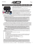
2. Now you should be ready to start the switch removal by removing the ignition switch label.
FIG.1
See Fig 1.
CAUTION: Wear safety glasses over your eyes.
See JIMS® catalog for Hundreds of top quality professional tools.
The last tools you will ever need to buy.
555 Dawson Drive, Camarillo, CA 93012 Phone 805-482-6913 • Fax 805-482-7422
1
No.778-IS
Rev N/C
11/10
A Division of Thiessen Products, Inc.
Instruction Sheet For Tool #778
3. Next, use a 3/8” drive ratchet wrench and short extension.
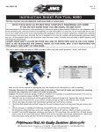
Place JIMS® No.788 tool on the end of the extension with pins
facing outward. See Fig 2.
4. Position the 2 pins on tool against the switch face nut. Locate
pins in plate holes. See Fig 3.
5. Turn counter-clockwise to loosen face nut. See Fig 4.
6. Refer to H-D service manual for removal of the the switch from
frame.
Switch Installation:
1. Follow H-D service manual for installation of switch in frame FIG.2
and correct positioning to engage fork lock.
2. Once switch is in position in the frame apply No. 243 blue
Loctite to the I.D. of threads of the face nut and thread on by
hand in a clockwise direction onto the switch body. Next use
the JIMS tool No.788 and using a 3/8” drive torque wrench
and tighten to H-D specification’s per manual. See Fig. 4
3. Last step is to install a new switch label. This needs to be positioned correctly before final installation. See H-D service manual. Notice that there is a location dimple on frame for positioning the label correctly. See Fig 1.
FIG.3
Face Nut
FIG.4
555 Dawson Drive, Camarillo, CA 93012 Phone 805-482-6913 • Fax 805-482-7422
2