1
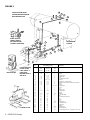
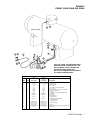
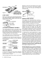
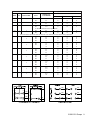
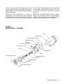
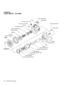
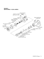
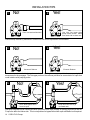
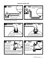
IF101G
IMPORTANT
INSTRUCTIONS
CORO-FLO® PUMPS
C SERIES
DS/DL SERIES
F SERIES
Warning: (1) Periodic inspection and maintenance of Corken products is essential. (2) Inspection, maintenance and installation of Corken products must be made
only by experienced, trained and qualified personnel. (3) Maintenance, use and installation of Corken products must comply with Corken instructions, applicable laws
and safety standards (such as NFPA Pamphlet 58 for LP-Gas and ANSI K61. 1-1972 for Anhydrous Ammonia). (4) Transfer of toxic, dangerous, flammable or explosive
substances using Corken products is at user’s risk and equipment should be operated only by qualified personnel according to applicable laws and safety standards.
The Model and Serial Numbers are shown on the nameplate of the unit. Record this information for future
reference.
Model No.
Serial No.
Date Purchased
Date Installed
Purchased From
Installed By
WARNING
Install, use and maintain this equipment according to Corken’s instructions and all applicable federal, state,
local laws and codes. Periodic inspection and maintenance is essential.
CORKEN ONE YEAR LIMITED WARRANTY
Corken, INC. warrants that its products will be free from defects in material and workmanship for a period
of 12 months following date of purchase from Corken. Corken products which fail within the warranty period
due to defects in material or workmanship will be repaired or replaced at Corken’s option, when returned,
freight prepaid to: CORKEN, INC., 3805 N.W. 36th Street, Oklahoma City, Oklahoma 73112. Parts subject
to wear or abuse, such as mechanical seals, blades, piston rings, and packing, and other parts showing
signs of abuse are not covered by this limited warranty. Also, equipment, parts and accessories not
manufactured by Corken but furnished with Corken products are not covered by this limited warranty and
purchaser must look to the original manufacturer’s warranty, if any. This limited warranty is void if the Corken
product has been altered or repaired without the consent of Corken. All implied warranties, including any
implied warranty of merchantability or expressed warranty period. CORKEN DISCLAIMS ANY LIABILITY
FOR CONSEQUENTIAL DAMAGES DUE TO BREACH OF ANY WRITTEN OR IMPLIED WARRANTY ON
CORKEN PRODUCTS. Transfer of toxic, dangerous, flammable or explosive substances using Corken
products is at the user’s risk. Such substances should be handled by experienced, trained personnel in
compliance with governmental and industrial safety standards.
CONTACTING THE FACTORY
Before you contact the factory, note the Model Number and Serial Number of your pump. The Serial
Number directs us to a file containing all information on material specifications and test data applying to your
specific pump. When ordering parts, the Corken Service Manual should be consulted for the proper Part
Numbers. ALWAYS INCLUDE THE MODEL NUMBER AND SERIAL NUMBER WHEN ORDERING PARTS.
TABLE OF CONTENTS
PRINCIPLES OF THE CORKEN CORO-FLO® PUMP . . . . . . . . . . . . . . . . . . . . . . . . . . . . . . . . . . . . . . . . . Page 4
EXCLUSIVE FEATURES OF YOUR CORKEN CORO-FLO® PUMP . . . . . . . . . . . . . . . . . . . . . . . . . . . . . . Page 4
INSTALLATION OF YOUR CORKEN CORO-FLO® PUMP . . . . . . . . . . . . . . . . . . . . . . . . . . . . . . . . . . . . . Page 4
Inlet Piping Should Include the Following . . . . . . . . . . . . . . . . . . . . . . . . . . . . . . . . . . . . . . . . . . . . . Page 5
Outlet Piping Should Include the Following. . . . . . . . . . . . . . . . . . . . . . . . . . . . . . . . . . . . . . . . . . . . Page 5
By-Pass System Must Include the Following . . . . . . . . . . . . . . . . . . . . . . . . . . . . . . . . . . . . . . . . . . . Page 5
Pump Foundation F-Models . . . . . . . . . . . . . . . . . . . . . . . . . . . . . . . . . . . . . . . . . . . . . . . . . . . . . . . . Page 5
Level Base . . . . . . . . . . . . . . . . . . . . . . . . . . . . . . . . . . . . . . . . . . . . . . . . . . . . . . . . . . . . . . . . . . . . . . Page 8
Coupling Alignment F-Models . . . . . . . . . . . . . . . . . . . . . . . . . . . . . . . . . . . . . . . . . . . . . . . . . . . . . . Page 8
Back-Up Wrench . . . . . . . . . . . . . . . . . . . . . . . . . . . . . . . . . . . . . . . . . . . . . . . . . . . . . . . . . . . . . . . . . Page 8
Driver Installation . . . . . . . . . . . . . . . . . . . . . . . . . . . . . . . . . . . . . . . . . . . . . . . . . . . . . . . . . . . . . . . . Page 8
WIRE SIZE CHART FOR WIRING OF YOUR ELECTRIC MOTOR . . . . . . . . . . . . . . . . . . . . . . . . . . . . . . . Page 9
OPERATION OF YOUR CORO-FLO® PUMP . . . . . . . . . . . . . . . . . . . . . . . . . . . . . . . . . . . . . . . . . . . . . . . Page 10
FILLING NEW CYLINDERS AND TANKS . . . . . . . . . . . . . . . . . . . . . . . . . . . . . . . . . . . . . . . . . . . . . . . . . Page 10
CARE OF YOUR CORO-FLO® PUMP . . . . . . . . . . . . . . . . . . . . . . . . . . . . . . . . . . . . . . . . . . . . . . . . . . . . Page 10
REPAIR SERVICE ON YOUR CORO-FLO® PUMP . . . . . . . . . . . . . . . . . . . . . . . . . . . . . . . . . . . . . . . . . . Page 10
PARTS DETAILS - C-MODEL . . . . . . . . . . . . . . . . . . . . . . . . . . . . . . . . . . . . . . . . . . . . . . . . . . . . . . . . . . Page 11
PARTS DETAILS - F-MODEL . . . . . . . . . . . . . . . . . . . . . . . . . . . . . . . . . . . . . . . . . . . . . . . . . . . . . . . . . . Page 12
PARTS DETAILS - DS/DL MODEL . . . . . . . . . . . . . . . . . . . . . . . . . . . . . . . . . . . . . . . . . . . . . . . . . . . . . . Page 13
INSTALLATION TIPS . . . . . . . . . . . . . . . . . . . . . . . . . . . . . . . . . . . . . . . . . . . . . . . . . . . . . . . . . . . . . . . . Page 14
PRINCIPLES OF THE CORKEN
CORO-FLO® PUMP
The CORKEN Coro-Flo Pump is a special type of
pump known as a turbine or regenerative pump. The
liquid flows into the inlet nozzle and into the
passageway on each side of an impeller (the rotating
element) and is recirculated constantly between the
vanes or teeth of the impeller and this passageway
as the impeller rotates. The fluid makes a complete
revolution in the pump case and is diverted out the
outlet nozzle. The horsepower required to drive the
pump increases as the differential pressure
increases, but the capacity decreases at the same
time. (Differential pressure is the difference between
the pressure at the inlet of the pump and at the outlet
of the pump.)
The impeller is the only moving part and has no
contact with the casing. Consequently, practically no
wear occurs to the impeller, even when pumping
volatile liquids such as LP-gas or ammonia which
have little lubricating qualities.
EXCLUSIVE FEATURES OF YOUR
CORKEN CORO-FLO® PUMP
The pumping of volatile liquids is one of the most
difficult of all pumping jobs. Unlike other pumping
operations, more attention must be given to the design,
manufacture installation and operation of the pump.
In addition to being a pump type especially suited for
handling volatile liquids, your CORO-FLO PUMP has
a number of features which help to make it more
easily operated and maintained.
The CORO-FLO PUMPS of this series are
manufactured directly connected to the electric motor
or with their own frame for connection to a separate
driver by means of a flexible coupling. The closecoupled pumps are the models C10, C12, C13 and
C14. The frame pumps are available in the F- and
DS/DL-models with the following pump sizes: 9, 10,
12, 13, 14 and 15.
UNDERWRITERS' LABORATORIES, INC. have
tested and inspected the CORO-FLO PUMPS of this
series and have listed them for use in the handling of
LP-gas and ammonia fluids. The nameplate on the
pump shows the UL label.
DUCTILE IRON, the metal with the strength of steel,
has been used in the manufacture of this pump for
parts under pressure of the liquid.
4 CORO-FLO Pumps
THE IMPELLER floats on a shaft and may be replaced
easily without disturbing the piping or driver by simply
removing the cover. No special tools are needed.
THE MECHANICAL SEAL ASSEMBLY may be
replaced easily by removing the cover and the
impeller, and without disturbing the piping or driver.
No special tools are needed.
THE PUMP NOZZLES MAY BE ROTATED into four
different positions, 90 degrees apart, if desired.
A BYPASS CONNECTION, 3/4" pipe thread, has
been located on the outlet nozzle to make the piping
of the pump more simple.
PRESSURE GAUGE CONNECTIONS, 1/4" pipe
thread, have been located on the outlet nozzle.
MOTORS on models C10, C12, C13 and C14 are
explosion-proof, Class I, Group D - UL and CSA
listed. The C10, C12 and C13 motors are all single
phase. 60 Hertz (50/60 Hertz on C13 only), 3450
RPM, 115/230 volt. The C14 motor is three-phase,
60 Hertz, 3450 RPM, 230/460 bolts. Corken can
provide manual motor starters for models C10, C12
and C13 with a built-in thermal overload protection.
Both motor-mounted and wall-mounted manual
starters are available for models C10, C12 and C13.
Models C11, C12 and C13 pump motors can be
provided with either a motor-mounted or wallmounted manual motor starter with built-in thermal
overload protection. These motors (after pump serial
number TS185540) are provided with a conduit seal
in the 3/4" NPT rigid galvanized steel nipple, fulfilling
the 1996 requirement of NFPA 70-NEC, paragraphs
501.5.a.1 & 3. Separate motor starters with overload
protection must be provided for the model C14 and
all F series pumps.
INSTALLATION OF YOUR CORKEN
CORO-FLO® PUMP
THE INSTALLATION OF A CORO-FLO PUMP is a
simple matter. However, in order for the pump to
deliver the performance you expect, the principles
discussed in this book must be followed exactly. The
piping details are furnished to illustrate methods
proved by hundreds of installations. Your own needs
may require some slight variations, but they must be
slight, and no compromise made.
For more detailed piping arrangements, request
Engineering Data book Z400. For a discussion of
pumping from underground tanks see Corken
Engineering Bulletin #6.
8. The minimum inlet piping sizes shown in Figures
1 and 2 must be observed.
IF IT IS DESIRABLE TO ROTATE THE NOZZLES of
the pump to a new position, remove the four cap
screws connecting the pump case (Figures 7, 8, 9)
to the motor or the frame. Be careful to do this without
moving the case away from the motor or frame;
otherwise, the mechanical seal may be damaged.
1. A pressure gauge should be installed in the
opening provided on the outlet nozzle or in the
outlet piping near the pump. This pressure gauge
will tell you the complete story of the operation
inside your pump. Be sure you have one installed.
NO PUMP CAN DISCHARGE MORE LIQUID THAN
IT RECEIVES, so the location and the inlet piping
must be given careful attention. If the inlet piping is
inadequate to supply the demand of the pump, you
may expect trouble! The inlet line sizes shown on
Figures 1 and 2 are the smallest size piping you can
use with success.
THE PUMP MUST BE LOCATED AS NEAR THE
STORAGE TANK as possible. The complete inlet
line, including the vertical line from the tank must not
exceed 12 feet in length. The bottom of the tank must
be at least two feet above the pump inlet nozzle, and
four feet should be considered standard.
THE INLET SHOULD INCLUDE THE
FOLLOWING:
1. The tank excess flow valve should have a flow rate
of 1-1/2 to 2 times the capacity of the pump. Do
not use an EVF without knowing its flow capacity.
2. The tank shutoff valve should be an angle valve
or a free flow type – not a standard globe valve.
3. A strainer of the "Y" type, with 1/16" mesh screen,
must be on the inlet line of the pump. For simpler
inlet lines use a Corken 1836-X1 Right Angle
Strainer to replace an elbow and "Y" strainer.
4. A flexible connection should be used on the pump
inlet or outlet to care for piping strains.
5. Unions must be installed near the pump inlet and
outlet nozzles.
THE OUTLET PIPING SHOULD
INCLUDE THE FOLLOWING:
2. A hydrostatic relief valve is required to be installed
in the outlet piping.
3. If the outlet piping exceeds 50 feet in length, a check
valve should be installed near the pump outlet.
4. The minimum outlet piping sizes shown in Figures
1 and 2 must be observed.
THE BYPASS SYSTEM MUST INCLUDE
THE FOLLOWING:
1. The pump bypass system must be installed. Without
this system, the pump has little chance of performing.
2. A CORKEN B166 BYPASS VALVE (a special valve
to vent the pump of vapors and to act as a
differential relief valve) makes the ideal installation.
3. The bypass line must rise uninterrupted to an
opening in the vapor section of the storage tank.
The tank fitting must be either an excess flow
valve or a vapor return valve; it should never be a
filler valve or a back check valve.
PUMP FOUNDATION F-MODELS
Every pump deserves a firm, neat concrete
foundation. There are many ways to construct a
foundation, and the example in Figure 3 is only a
suggestion. The important features are to make the
foundation level, and deep enough to get below the
frost line for your locality.
6. An eccentric swage should be used at the pump
inlet nozzle to change line size (flat side up.)
7. The inlet line must be level or slope downward to
the pump.
CORO-FLO Pumps 5
FIGURE 1
23
VAPOR LINE FROM METER
VAPOR ELIMINATOR OR METER
BACK PRESSURE VALVE
24A
24
21
22
25
20
18
19
1
2A 2
3
EITHER CORO-FLO
FRAME F-MODELS
OR CLOSE-COUPLED
C-MODELS CAN BE USED.
17
13A
13
12
4’ - 0”
RECOMMENDED
DISTANCE
18
11
15 14
10
12
11
4
6
8
9
5
5A
7
9A
16
Item
No.
MOTOR FUELING
IF DISCHARGE LINE
IS OVER 50 FEET
LONG, INSTALL A
CHECK VALVE
BETWEEN VALVE 15
AND TEE 16.
CYLINDER FILLING
6 CORO-FLO Pumps
1
2
2A
3
4
5
5A
6
7
8
9
9A
10
11
12
13
13A
14
15
16
17
18
19
20
21
22
23
24
24A
25
26
Description
Size of Fitting in Inches
Model
C10
F9, F10
Model
C12, C13
F12, F13
Model
C14
F14
1-1/4
1-1/4
--1-1/4
1-1/4
1-1/4
--1-1/4
1-1/4
1-1/4
1-1/4
--1
1
1
1 x 3/4
--1 x 1/2
1/2
1
3/4
3/4
3/4
3/4
--3/4
3/4
3/4
--3/4
1/4
2
--2 x 1-1/2
1-1/2
1-1/2
1-1/4
1-1/2 x 1-1/4
1-1/2
1-1/2
1-1/2
1-1/2
--1
1
1
1 x 3/4
--1 x 1/2
1/2
1
3/4
3/4
3/4
3/4
--3/4
3/4
3/4
--3/4
1/4
2
2
--2
2
2
--2
2
2
--2 x 1-1/2
1
1
1
--1
1 x 1/2
1/2
1
1
1
1
1
1 x 3/4
3/4
1
--1 x 3/4
3/4
1/4
Excess Flow Valve
Nipple
Swage Nipple
Shutoff Valve
Tee
Double Check Filler Valve
Bushing
Strainer with 1/16 Mesh Screen
Flexible Hose Connection with Male Hose Connection
Union
Nipple
Swage Nipple
Union
Tee
Shutoff Valve
Swage Nipple
Nipple
Bushing
Hydrostatic Relief
Ell
Corken Bypass Valve B-166
Ell
Union
Tee
Swage Nipple
Vapor Return Valve
Angle Valve
Nipple
Swage Nipple
Excess Flow Valve
Pressure Gauge with 1/4” x 2” Nipple and 1/4” 90° Ell
FIGURE 2
PIPING YOUR CORO-FLO PUMP
12
11
COPPER TUBING
1
2
3
18
17
14
4
10
9
13
5
8
7
16
15
19
19
6
NOTE: PIPE, VALVES, FITTINGS AND ELECTRICAL
WIRING MUST BE IN ACCORDANCE WITH LOCAL,
STATE OR FEDERAL CODES, STANDARDS AND
REGULATIONS HAVING JURISDICTION.
REF. NFPA 58 “STANDARDS FOR THE HANDLING
OF LIQUEFIED PETROLEUM GASES”
BILL OF MATERIALS
C-10, F10
QUAN.
SIZE, INCHES
C12, F12
C13, F13
SIZE, INCHES
1
2
3
4
5
6
7
8
9
10
11
1
1
1
1
1
1
1
1
1
1
1
1-1/4
1-1/4 x 4
1-1/4
1-1/4
1-1/4
1-1/4
1/4 NPT
1 x 3/4
3/4
3/4
3/4 FPT x 1/2
SAE Flare
1-1/4
1-1/2 x 1-1/4 Swage
1-1/2
1-1/2
1-1/2
1-1/2
1/4 NPT
1 x 3/4
3/4
3/4
3/4 FPT x 5/8
SAE Flare
12
13
14
1
1
1
3/4 x 1/2
1/2 x 10’-0”
None
3/4 x 10’-0”
15
16
1
1
17
1
18
19
1
2
1/2
1/2 MPT x 1-3/4
6 Acme (Female)
1/4 FPT x 1-3/4
6 Acme (Male)
1/4 MPT x Male POL
1-1/4 x 4
3/4
3/4 MPT x 1-3/4
6 Acme (Female)
1/4 FPT x 1-3/4
6 Acme (Male)
1/4 MPT x Male POL
1-1/2 x 4
ITEM
DESCRIPTION
Excess Flow Valve
Swage or Nipple
LPG Shutoff Valve
X.H. 90˚ Ell
L.P.G. Strainer with 1/16 Mesh Screen
X.H.G.J. Union
Pressure Gauge 2-1/2” Face bottom connected
Concentric Steel Swage
X.H. Tee
Corken By-Pass Valve with Hydrostatic Relief
Tube Adapter
O.D. Tubing
Excess Flow Valve
Hex Steel Bushing
Single Wire Braid Hose with Male
Couplings Both Ends
L.P.G. Shutoff Valve
Filler Valve Coupling
Adapter
Cylinder Filling Connector with Handwheel Extension
X.H. Nipple
CORO-FLO Pumps 7
threads are clean and well doped with the proper
thread seal for the service. Avoid using excessive
dope, for it may enter the pump and damage the
mechanical seal.
Figure 3
LEVEL BASE
After the concrete has set, check the pump base for
level. Drive metal shims under the base near the
anchor bolts as below. Tighten anchor bolts and
recheck the base for level.
Figure 4
COUPLING ALIGNMENT F-MODELS
The coupling alignment must be near perfect to give
quiet, long-life service to the pump and driver. The
pump and driver shafts are carefully aligned at the
factory but always should be checked after the pump
is installed and before the initial operation.
Lay a straight edge across coupling halves, top, and
side; both positions must line up to be correct.
If misalignment exists, adjust the shims between the
pump base and the foundation until exact alignment
is accomplished.
Figure 5
BACK-UP WRENCH
To keep from breaking the pump nozzle or springing
the pump out of alignment, always use a back-up
wrench as shown in Figure 6.
Use the proper wrench size, and be sure the pipe
8 CORO-FLO Pumps
Figure 6
DRIVER INSTALLATION
THE WIRING OF YOUR ELECTRIC MOTOR is
extremely important and must be done by a competent
electrical contractor. The wire size chart on page 6
indicates the minimum standards for wire sizes.
Improper motor wiring will cause you to experience
expensive motor difficulties from low voltage. If you
suspect you have low voltage, call your power
company. Connecting your motor for the voltage you
have available is important too. Be sure your motor
is connected to the proper voltage. Connecting to
improper voltage will completely destroy your motor.
In explosion-proof motor applications in humid
climates, the normal breathing and alternating
temperatures of the motor (warm during operation
and cold when stopped) will often cause moist air to
be drawn into the motor housing. This moist air will
condense and may eventually add enough free water
to the inside of the motor to cause it to fail. To prevent
this, make a practice of running the motor and pump
at least once a week on a bright, dry day for an hour
or so (pump through the bypass system). During this
time, the motor will heat up and vaporize the
condensed moisture. No motor manufacturer will
guarantee his explosion-proof or totally enclosed
motor against damage from moisture.
ENGINE DRIVERS pose a special consideration.
The manufacturer's instructions must be followed.
When the CORO-FLO PUMP is equipped with an
engine from the factory, the engine speed should
normally not exceed 3600 rpm. Excessive engine
speed will overload the engine and cause early
failure. The engine loses 3% of its power for every
1000 feet above sea level, so if your installation is at
a higher altitude than normal, consult the factory.
MOTOR
MODEL
HP.
MOTOR PHASE
(a) RECOMMENDED WIRE SIZE, AWG
VOLTS
LENGTH OF RUN IN FEET
APPROX. FULL
LOAD AMPERES
0-100
TO 200
TO 300
C9
C10
3/4
1
115
230
9.0
5.0
12
12
8
12
6
12
C12
1
1
115
230
16.0
8.0
8
12
6
12
4
10
C13
2
1
115
230
20.0
10.0
8
12
4
10
2
8
C14
3
3
12
10
12
8
*P1 Should be connected to the ungrounded line.
230
460
8.0
4.0
12
12
Pump must rotate in the direction shown on pump case. If not, switch any two of the three incoming 3 phase lines.
3/4
1
3
1
1
3
1-1/2
1
3
2
1
3
3
1
3
5
1
3
7-1/2
1
3
T3
115
230
230
460
10.0
5.0
2.8
1.4
12
12
12
12
8
12
12
12
6
12
12
12
115
230
230
14.0
7.0
3.6
1.8
10
12
12
12
6
12
12
12
6
12
12
12
115
230
230
460
18.0
9.0
5.2
2.6
8
12
12
12
6
12
12
12
4
10
12
12
115
230
230
460
24.0
12.0
6.8
3.4
8
12
12
12
4
10
12
12
2
8
12
12
115
230
230
460
34.0
17.0
9.6
4.8
6
12
12
12
4
8
12
12
2
8
12
12
115
230
230
460
56.0
28.0
15.2
7.6
4
10
12
12
1
6
12
12
1/0
4
10
12
230
230
460
40.0
22.0
11.0
8
10
12
6
10
12
4
8
12
LINE
T1
T1
T1 T1
L1
T3
T4
LINE
T4
L2
LINE
LINE
LINE
LINE
•
LINE
T2
LINE
L1
LINE T2
T2
LINE
T2
L2
CORO-FLO Pumps 9
OPERATION OF YOUR
CORO-FLO® PUMP
The following steps should be performed for the
initial pumping operation:
pressure down to a reasonable limit. Don't blame
your pump for not filling a small container! A properly
fitted cylinder and filling manifold or connection will
permit filling with not more than 50 to 60 psi
differential pressure.
1. Close shutoff valve on the end of the delivery hose.
2. Open the storage tank bottom shutoff valve.
3. Open the storage tank shutoff valve of the
bypass system.
4. Check the motor for the proper voltage. (See
instructions under driver installation.)
5. Start the pump and circulate liquid through the
bypass system.
6. Adjust the B166 bypass valve by turning the
adjusting screw out until the pump pressure
gauge shows nearly the same pressure it did
before you started the pump. Screw the adjusting
screw in until the pressure gauge indicates the
pump is starting to lose discharge pressure (you
will know this by the rapid fluctuating of the
pointer); then back the adjusting screw out a turn
or two until the pressure gauge again indicates a
steady pressure. Lock the lock nut, and permit the
pump to circulate liquid for a half hour or more. If
the motor overload protection device stops the
motor during this period, this indicates the bypass
system valve is set too high and should be
readjusted by turning the adjusting screw out until
the motor will run for this period.
FILLING NEW CYLINDERS AND TANKS
All new containers are full of air and since air will not
liquefy under reasonable filling pressures, it must be
purged. To assure relatively easy filling and the
proper gas supply to burners and carburetors,
purging air from new containers is esseÏntial.
Some cylinders are difficult to fill because they are
equipped with a fill tube that extends down into the
liquid portion of the container. If possible, these
cylinders should be refitted, so the incoming liquid
enters the vapor section of the cylinder. If refitting is
impossible or impractical, rock the cylinder as it is
being filled so that liquid will splash up into the vapor
section – this will help keep the cylinder filling
10 CORO-FLO Pumps
CARE OF YOUR CORO-FLO® PUMP
The only maintenance necessary on this pump is to
lubricate the bearings about once every six months.
The Bearings have been lubricated at the factory for
the initial operation.
LUBRICATION FOR MODELS C10, C12, C13
These models are equipped with lifetime lubricated
bearings.
LUBRICATION FOR MODELS F9, F10, F12, F13,
F14, F15, DS/DL 9, 10, 12, 13, 14, AND 15
There are two bearings on the pump frame of these
models that require lubrication. In addition, if the
pump is driven by a motor there may be two bearings
on the motor to lubricate at the same time you
lubricate the pump bearings. If the driver is an engine,
follow the engine manufacturer's instructions.
LUBRICATING BALL BEARING IS SIMPLE. Use
only Ball Bearing Grease – nothing else will do.
Remove the plug or fitting over the bearing, add a
small amount of grease, and run the pump and driver
for several minutes with the plug removed. The
bearings will pump out the excess grease. Replace
the plug.
REPAIR SERVICE ON YOUR
CORO-FLO® PUMP
After a long service life, repairs are limited to
replacing the impeller or mechanical seal.
The only wearing part influencing the pumping action
is the impeller, so we suggest the pump be given an
"efficiency" test before any attempt is made to repair
it. The trouble may lie in the piping system rather than
in the pump. If the pump will still produce as much
differential pressure when circulating through the
bypass system as it did when new, you may be sure
your problem is elsewhere. If the pump does not
produce as much pressure as it did originally, remove
the cover in Figure 7, 8 or 9, and inspect the impeller.
If visual inspection indicates the impeller is in good
condition, remove the thin shim gasket and replace
the cover. Many times this procedure will adjust for
slight Impeller wear. If the Impeller is badly damaged,
it must be replaced.
use for pulling. The new impeller must be a good slip
fit on the shaft; it should "float" on the shaft, so it may
be necessary to sand the shaft lightly to get the
proper fit.
REPLACING THE IMPELLER is a matter of
removing the cover and removing the old impeller
from the shaft. If the old impeller is tight on the shaft,
threaded bolt holes are provided in the impeller to
REPLACING THE MECHANICAL SEAL is a simple
matter, and replacement parts are immediately
available. Clear instructions are furnished with the
replacement seal assembly for its installation.
FIGURE 7
PARTS DETAILS - C MODELS
Motor
Woodruff Key
Socket Head Cap Screw
Pan Head Screw
Nameplate
Pipe Plug, 3/4” NPT
Pipe Plug, 1/4” NPT
O-ring
Adapter Ring
Case
Hex Head Cap Screw
Housing Adj. Shim
Seal Housing
Seal Assembly
Impeller
O-ring
Case Clearance Shim
Cover
CORO-FLO Pumps 11
FIGURE 8
PARTS DETAILS - F MODELS
Pan Head Screw
Case
Pipe Plug 3/4” NPT
Nameplate
Pipe Plug 1/4” NPT
O-ring
Housing Adj. Shim
SOC Head Screw
Grease Zerk
Seal Housing Steel
Seal Assembly
Impeller
O-ring
Case Clearance
Shim
Cover
Frame
Ball Bearing
Key
Shaft
Hex Head
Cap Screw
12 CORO-FLO Pumps
#5 Woodruff Key
Bearing Retainer Ring
Ball Bearing
Bearing Retainer Ring
Grease Seal
Bearing Cap
Bearing Retainer Ring
FIGURE 9
PARTS DETAILS - DS/DL MODELS
Pan Head Screw
Pipe Plug, 3/4” NPT Nameplate
Case
Pipe Plug, 1/4” NPT
O-ring
Housing Adj. Shim
Seal Housing Steel
Seal Assembly
Seal Pin
Impeller
Socket Head Screw
Grease Zerk
O-ring
Case Clearance Shim
Cover
Hex Head
Cap Screw
Frame DS/DL
Bearing Retainer Ring
Ball Bearing
Key
Shaft
#5 Woodruff Key
Ball Bearing
Bearing Retainer Ring
Grease Seal
Bearing Cap
Bearing Retainer Ring
CORO-FLO Pumps 13
INSTALLATION TIPS
1
No!
2
Yes!
Use inlet line larger than
pump suction nozzle. Same
size nozzle OK on short runs.
Don’t use restricted inlet line!
Pressure drop caused by restriction in suction line will cause vaporization and cavitation.
3
No!
4
Yes!
Eccentric Reducer
Concentric Reducer
An eccentric reducer should always be used when reducing into any pump inlet where vapor might be
encountered in the pumpage. The flat upper portion of the reducer prevents an accumulation of vapor that
could interfere with pumping action.
5
No!
Don’t allow bypass line to
have low spot.
6
Yes!
Keep return line level or go
up toward tank!
Low spots in bypass line can collect liquid which prevents normal vapor passage for priming purposes just like the
P trap in the drain of a kitchen sink. This is not a problem for bypass lines where vapor elimination is not required.
14 CORO-FLO Pumps
INSTALLATION TIPS
7
Yes!
8
No!
Never locate pump above level
of liquid feeding pump. Product
must be able to flow by gravity
into pump.
Always locate pump below tank
level
...the lower the better!
Since liquefied gases boil when drawn into a pump by its own suction, the pump must be fed by gravity flow
to give stable, trouble-free operation.
No!
9
Back Check Valve
Positive closure of back check valve
prevents proper vapor return for
pump priming.
11
No!
Don’t pipe bypass line
back into suction piping!
Heat
Building
in
recirculated
products
causes flashing of liquid
to vapor with immediate
cavitation and ultimate
dry-running. This is why
the bypass relief valves
which are built into many
positive displacement
pumps should not be used for normal bypass action when handling liquefied
gases. The internal valve should be considered to be a back-up safety relief
in in addition to a back-up safety relief in addition to a back-to-tank bypass
valve and should be set to relieve at pressure 10 to 20 psi higher than the
working bypass. Some built-in bypass valves have the capability of being
piped back-to-tank so check with the pump manufacturer.
Yes!
10
Excess Flow Check Valve
Necessary for proper vapor elimination
when using priming type bypass valves.
12
Yes!
Always pipe bypass
back to tank! Make
sure bypass line is
large enough to handle
full pump flow without
excessive pressure
build-up. Note that
bypass line must be
capable of bypassing full pump
capacity without excessive
pressure build-up. High pressure
rise can cause bypass valve to
chatter and vibrate.
CORO-FLO Pumps 15
P.O. Box 12338, Oklahoma City, OK 73157
3805 N.W. 36th St., Oklahoma City, OK 73112
Phone (405) 946-5576 • Fax (405) 948-7343
E-mail [email protected]
Web address www.corken.com
Printed in U.S.A.
November 1999