1
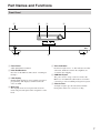
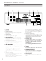
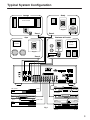
Multizone Amplifier
MZA-4.7
Instruction Manual
WARNING:
TO REDUCE THE RISK OF FIRE OR ELECTRIC
SHOCK, DO NOT EXPOSE THIS APPARATUS
TO RAIN OR MOISTURE.
CAUTION:
TO REDUCE THE RISK OF ELECTRIC SHOCK,
DO NOT REMOVE COVER (OR BACK). NO
USER-SERVICEABLE PARTS INSIDE. REFER
SERVICING
TO
QUALIFIED
SERVICE
PERSONNEL.
WARNING
AVIS
RISK OF ELECTRIC SHOCK
DO NOT OPEN
RISQUE DE CHOC ELECTRIQUE
NE PAS OUVRIR
The lightning flash with arrowhead symbol, within an
equilateral triangle, is intended to alert the user to the
presence of uninsulated “dangerous voltage” within
the product’s enclosure that may be of sufficient
magnitude to constitute a risk of electric shock to
persons.
The exclamation point within an equilateral triangle is
intended to alert the user to the presence of important
operating and maintenance (servicing) instructions in
the literature accompanying the appliance.
Important Safety Instructions
1.
2.
3.
4.
5.
6.
7.
8.
9.
10.
11.
12.
13.
14.
2
Read these instructions.
Keep these instructions.
Heed all warnings.
Follow all instructions.
Do not use this apparatus near water.
Clean only with dry cloth.
Do not block any ventilation openings. Install in
accordance with the manufacturer’s instructions.
Do not install near any heat sources such as radiators, heat registers, stoves, or other apparatus
(including amplifiers) that produce heat.
Do not defeat the safety purpose of the polarized or
grounding-type plug. A polarized plug has two
blades with one wider than the other. A grounding
type plug has two blades and a third grounding
prong. The wide blade or the third prong are provided for your safety. If the provided plug does not
fit into your outlet, consult an electrician for
replacement of the obsolete outlet.
Protect the power cord from being walked on or
pinched particularly at plugs, convenience receptacles, and the point where they exit from the apparatus.
Only use attachments/accessories specified by the
manufacturer.
Use only with the cart, PORTABLE CART WARNING
stand, tripod, bracket, or
table specified by the
manufacturer, or sold with
the apparatus. When a cart
is used, use caution when
moving the cart/apparatus
combination to avoid S3125A
injury from tip-over.
Unplug this apparatus during lightning storms or
when unused for long periods of time.
Refer all servicing to qualified service personnel.
Servicing is required when the apparatus has been
damaged in any way, such as power-supply cord or
plug is damaged, liquid has been spilled or objects
have fallen into the apparatus, the apparatus has
been exposed to rain or moisture, does not operate
normally, or has been dropped.
15. Damage Requiring Service
Unplug the apparatus from the wall outlet and refer
servicing to qualified service personnel under the
following conditions:
A. When the power-supply cord or plug is damaged,
B. If liquid has been spilled, or objects have fallen
into the apparatus,
C. If the apparatus has been exposed to rain or
water,
D. If the apparatus does not operate normally by
following the operating instructions. Adjust only
those controls that are covered by the operating
instructions as an improper adjustment of other
controls may result in damage and will often
require extensive work by a qualified technician
to restore the apparatus to its normal operation,
E. If the apparatus has been dropped or damaged in
any way, and
F. When the apparatus exhibits a distinct change in
performance this indicates a need for service.
16. Object and Liquid Entry
Never push objects of any kind into the apparatus
through openings as they may touch dangerous voltage points or short-out parts that could result in a
fire or electric shock.
The apparatus shall not be exposed to dripping or
splashing and no objects filled with liquids, such as
vases shall be placed on the apparatus.
Don’t put candles or other burning objects on top of
this unit.
17. Batteries
Always consider the environmental issues and follow local regulations when disposing of batteries.
18. If you install the apparatus in a built-in installation,
such as a bookcase or rack, ensure that there is adequate ventilation.
Leave 20 cm (8") of free space at the top and sides
and 10 cm (4") at the rear. The rear edge of the shelf
or board above the apparatus shall be set 10 cm (4")
away from the rear panel or wall, creating a flue-like
gap for warm air to escape.
Quick Install Guide
Unpacking
Immediately upon receiving your MZA-4.7 inspect the
carton for evidence of mishandling during shipment.
Then carefully unpack the unit and inspect for damage.
Please save the shipping carton and all inner packing
materials in the event that the MZA-4.7 needs to be
shipped for service or moved to a new location.
Should you discover that the MZA-4.7 has been damaged
during shipping please contact your dealer immediately.
1. Check website for latest firmware, and upload if not
current.
2. If adding an amplifier to an exiting stack or combining amplifiers all firmware must be the same on all
amplifiers
3. Zone setting. The units all ship with zones 1,2,3,4
already setup.
To add additional amplifiers to a stack the zones
must be changed on the additional amplifiers. If
there are zone duplications in a stack of amplifiers
the zones with the same number will exactly mirror
each other’s operation.
To change an amplifier zone follow the following
steps.
•
•
Do not connect the expansion bus cable.
From the front facia rotate the Knob to select the
appropriate amplifier – turn it on, and then select the
“More” menu (right arrow). Scroll through the menu
and select “Set Zone” and change to the required
assignment pushing the Knob to set.
Table of Contents
Important Safety Instructions...............................2
Quick Install Guide ..............................................3
Supplied Accessories ..........................................3
Precautions .........................................................4
Features ..............................................................5
Part Names and Functions..................................7
Typical System Configuration..............................9
Controller Termination.......................................11
Advanced IR Control .........................................12
Multiple MZA-4.7 Stacks ...................................13
Zone Linking......................................................14
Automation ........................................................15
RS232 Protocol .................................................16
Menu Navigation ...............................................20
Programming Using IMC (Integra Music Center)......22
Specifications ....................................................28
Supplied Accessories
Make sure you have the following accessories:
AC Power Cable
4. Wire the keypads to the rear of the amplifier.
5. To setup the keypad follow the Controllers instruction manual, Briefly:
•
•
•
•
•
•
•
with a zone, press the SET key (behind the cover plate)
followed by the S2 key.
Turn the required amplifier zone ON and OFF twice.
The Keypad beeps signalling it has been successfully
zoned. The Keypad now controls that zone.
Learn codes into the Keypad by first selecting the
source button ie S3. Press the SET key followed by the
S1 key to enter keypad IR learning mode.
Press the button you want to learn an IR code into.
Align the remote with the front lower window and
press the button on the remote to donate the IR code to
that button. Continue learning codes for that source.
Press the SET key to exit learn mode.
Select the next source, ie S2. Then press SET followed
by S1 and repeat the learning process.
CD-ROM
*In catalogs and on packaging, the letter at the end of the product
name indicates the color. Specifications and operations are the
same regardless of color.
6. To prevent a user from changing the MZA-4.7’s
critical installation settings, “Setup Lockout” can be
selected in the Setup Menu. To enter the setup menu
press and hold the multi jog for > 10 second, scroll
through to “Setup Lockout” enter and select “Yes.”
The “Setup” and “More” menus on the amplifier are
no longer accessible to the user.
7. To unlock the MZA-4.7, return to the setup menu as
above. And enter the password: 1396
3
Precautions
1. Recording Copyright—Unless it’s for personal use
only, recording copyrighted material is illegal without the permission of the copyright holder.
2. AC Fuse
CAUTION:
FOR CONTINUED PROTECTION AGAINST
RISK OF FIRE REPLACE ONLY WITH SAME
TYPE T6.3A 250V FUSE.
REFER REPLACEMENT TO QUALIFIED SERVICE PERSONNEL.
3. Care—Occasionally you should dust the unit all
over with a soft cloth. For stubborn stains, use a soft
cloth dampened with a weak solution of mild detergent and water. Dry the unit immediately afterwards
with a clean cloth. Don’t use abrasive cloths, thinners, alcohol, or other chemical solvents, because
they may damage the finish or remove the panel lettering.
4. Power
WARNING
BEFORE PLUGGING IN THE UNIT FOR THE
FIRST TIME, READ THE FOLLOWING SECTION CAREFULLY.
AC outlet voltages vary from country to country.
Make sure that the voltage in your area meets the
voltage requirements printed on the unit’s rear panel
(e.g., AC 230 V, 50 Hz or AC 120 V, 60 Hz).
The power cord plug is used to disconnect this unit
from the AC power source. Make sure that the plug
is readily operable (easily accessible) at all times.
5. Never Touch this Unit with Wet Hands—Never
handle this unit or its power cord while your hands
are wet or damp. If water or any other liquid gets
inside this unit, have it checked by your Onkyo
dealer.
6. Handling Notes
• If you need to transport this unit, use the original
packaging to pack it how it was when you originally bought it.
• Do not leave rubber or plastic items on this unit
for a long time, because they may leave marks on
the case.
• This unit’s top and rear panels may get warm
after prolonged use. This is normal.
• If you do not use this unit for a long time, it may
not work properly the next time you turn it on, so
be sure to use it occasionally.
7. Speaker Shorts—Under no circumstances should
the speaker output terminals of the unit be short circuited, or connected to another output.
8. RS232 Connection—Avoid plugging the RS232
cable into the unit while power is connected.
9. Direct Sun light—Avoid installing the amplifier in
positions where the front panel is exposed to direct
sunlight – may cause control to become sluggish.
10. Controller Connection—Never connect more than
four controllers to the 12VDC power supply termi-
4
nals. The supply is internally fused and will open
circuit (self-resetting) Never connect the amplifier’s
12VDC terminals to an external power supply.
For U.S. models
FCC Information for User
CAUTION:
The user changes or modifications not expressly
approved by the party responsible for compliance could
void the user’s authority to operate the equipment.
NOTE:
This equipment has been tested and found to comply
with the limits for a Class B digital device, pursuant to
Part 15 of the FCC Rules. These limits are designed to
provide reasonable protection against harmful interference in a residential installation.
This equipment generates, uses and can radiate radio
frequency energy and, if not installed and used in accordance with the instructions, may cause harmful interference to radio communications. However, there is no
guarantee that interference will not occur in a particular
installation. If this equipment does cause harmful interference to radio or television reception, which can be
determined by turning the equipment off and on, the
user is encouraged to try to correct the interference by
one or more of the following measures:
• Reorient or relocate the receiving antenna.
• Increase the separation between the equipment and
receiver.
• Connect the equipment into an outlet on a circuit different from that to which the receiver is connected.
• Consult the dealer or an experienced radio/TV technician for help.
For Canadian Models
NOTE: THIS CLASS B DIGITAL APPARATUS
COMPLIES WITH CANADIAN ICES-003.
For models having a power cord with a polarized plug:
CAUTION: TO PREVENT ELECTRIC SHOCK,
MATCH WIDE BLADE OF PLUG TO WIDE SLOT,
FULLY INSERT.
Modèle pour les Canadien
REMARQUE: CET APPAREIL NUMÉRIQUE DE
LA CLASSE B EST CONFORME À LA NORME
NMB-003 DU CANADA.
Sur les modèles dont la fiche est polarisée:
ATTENTION: POUR ÉVITER LES CHOCS ÉLECTRIQUES, INTRODUIRE LA LAME LA PLUS
LARGE DE LA FICHE DANS LA BORNE CORRESPONDANTE DE LA PRISE ET POUSSER
JUSQU’AU FOND.
Features
Thank you for purchasing an Integra MZA-4.7 Multi-Zone Amplifier.
Please read this manual thoroughly before making connections and plugging in the unit.
Following the instructions in this manual will enable you to obtain optimum performance and listening
enjoyment from your new Multi-Zone Amplifier.
Please retain this manual for future reference.
Multi-Zone, Multi-Source, Video Switching
The MZA-4.7 has four separate preamplifiers and amplifiers, providing 4 zones of independent yet integrated
control.
There are seven stereo sources (S1 - S7) and an eighth
mono source (S8) typically used for paging applications.
Each zone has an eight-source composite video switcher,
so monitor screen’s in four different rooms may display
any of the eight sources (S1 - S8).
Preamplifiers and Outputs
Each zone has bass, treble, balance and loudness control.
These are accessed either from the front panel or IMC
(Integra Music Center) program.
The preamplifier output volume may be independent of
the amplifier volume, or made to track the amplifier with
an adjustable offset (± 20dB). The tracking feature is
ideal for passive subwoofer control, while the independent volume feature is useful for limited control in
closecoupled rooms.
A useful protection feature is “Maximum Volume limiting.” This limits the maximum volume of either the
amplifier or preamplifier.
Amplifier Power, Protection, and Clipping
Indicators
50 Watts RMS per channel into 8 ohms, capable of driving into 6 ohms.
The amplifiers are protected against short-term output
shorts.
The front panel zone indicators will flash red when the
zone amplifiers are overdriven into clipping.
Thermal Control
There are three progressive levels of thermal control:
• An internal fan is turned on to aid cooling.
• The amplifier volume is reduced 20dB.
• The amplifiers are shutdown until the temperature
reduces below the first level.
Care should be taken to ensure adequate ventilation – see
“Important Safety Instructions” on page 2.
USB, RS232 and IR Control
The MZA-4.7 may be controlled and monitored via
either the front Panel USB or rear panel RS232 serial
interface.
In multi amplifier installations where the amplifiers are
interconnected using an expansion bus cable, only one
USB or RS232 connection is required to control the
stack of amplifiers.
A MZA-4.7 may receive IR directly from the front panel
receiver or via the two “Controller Interface” connections.
There are zone specific IR commands and also a set of
global IR commands.
The commands are: ON, OFF, Standby (toggling), Mute,
Amp Volume Up, Amp Volume Down, Pre Volume Up,
Pre Volume Down, Source Selects, On with Source Specific commands.
The Global commands also include PRESET1 - PRESET 6, Alarm Enable, Alarm OFF, and 5 minute Sleep.
Real Time Clock
The MZA-4.7 is equipped with a real time clock.
The amplifier may be set up to function as an alarm
clock, so that at 6.30am in the morning 5 days a week,
the master bedroom zone could be made to turn on,
select tuner, and go to a specific volume. Multiple
Alarms are feasible (max of 6) However the Alarm
Enable & OFF commands act upon all programmed
Alarms.
The clock continues to operate typically > 48 hours without power – more than enough to keep the time current
during lengthy power outages.
IR Emitter Ports
There are 4 Buffered IR emitter Ports.
Two IR ports have routing, and are linked to their respective “Controller Interface” ports. These ports control
zone specific source components. Two IR ports are the
sum of both IR sources; these control the All zone source
components.
Presets and Paging
There are six amplifier presets and a page preset.
Presets 1 - 6 are momentary and cause the amplifier to go
to a predetermined setup, i.e. standby, volume & source
selection.
The presets may also be programmed with event scheduling, and are used by the alarm clock.
The “Page Preset” mode is for paging applications and is
invoked by a contact closure between the “0V” and the
“PG” terminals. When the contact closure is released the
amplifier zones return to their previous states.
Zone Linking
A zone may be programmed to link one other zone. Zone
linking ties the source selection together. It may also tie
the volume, and standby.
This is useful for closely coupled audio areas where it is
5
Features—Continued
advantageous to have different volume control but the
same source, or the same volume with separate standby
control. Zone linking is setup either via the front panel
user interface or by the IMC program.
32 Zones
There are 32 zones of possible control.
On a MZA-4.7 each zone must be different, however in
a multiple amplifier stack same zone amplifiers are possible – they simply mimic every parameter.
Expansion Bus
Data, IR, Amp-On & Audio sources are interconnected
via the expansion bus.
The expansion bus feature vastly simplifies the installation cabling of an amplifier stack.
One amplifier is connected to another using a 34-way
ribbon cable. Connections are made from the output of
the first amplifier to the input of the second etc.
All audio sources must be connected to the first amplifier.
Note: Video signals are not passed through the expansion bus.
Door Bell
Looped 1.5 second mono sounds can be generated as
part of a page preset.
Suitable “wav” files are uploaded to the unit using the
IMC program. IMC truncates the “wav” files to a suitable size.
12VDC 1A Power
Two 12VDC jacks are available for powering external
accessories – internally fused at 1A (Self-resetting).
Amplifier ON Status – “Amp-On”
Each zone has front panel ON status indication, and
12VDC OUT on the rear panel connector: (1, 2, 3, 4 &
#). The # “AMP ON” output is a logic “And” output, i.e.
if any zone is ON then the output will be 12V. This is
useful for driving a relay that connects AC power to
source equipment. The “AMP ON” output’s are protected against shorts. The “AMP ON” outputs default to
tracking the preamplifier ON status, but may optionally
be set to track the amplifier ON status using the IMC
program.
Power Failure Restoration
After an AC power outage the MZA-4.7 restores its settings to the pre-interrupted state.
All internal settings are stored in non-volatile memory,
except the clock that runs for at least 48 hours on stored
power.
Restore Defaults
The MZA-4.7 may be set to the default settings.
6
Restoring Defaults clears all memory and resets the zone
allocations to zones 1 - 4.
Setup Lockout
Locks access to the System Setup and More menus
where installation critical adjustments can be made.
Password = 1396
Firmware Upgradable
May be updated with the latest operational firmware,
using the USB Uploader program.
Provides a degree of future proofing, and flexibility.
Part Names and Functions
Front Panel
1
2
3
4
Multi Jog
Push to Enter
Zone
1
2
3
4
USB
MZA- 4.7
6 7
A Front Panel
Solid Aluminum front Panel.
B Infra-Red Receiver
Receiver for the MZA-4.7 IR control – Not IR pass
through!
C LCD display
Back lit LCD display for menu guided control and
programming. The display is dimmed when all
zones are OFF.
D Multi Jog
The display menus are navigated and selections
made using left and right rotation and pushes on the
knob.
5
7
E Zone Indicators
From left to right zone 1 - 4. The indicators are blue
when ON, and flash red when the amplifiers are
overdriven into clipping.
F USB Mini B port
The port is used to setup, control or monitor the
MZA-4.7. An USB mini cable must be used when
connecting to a PC or building management system.
G Chassis Feet
Set high enough to provide unrestricted airflow
through the chassis for convection cooling.
7
Part Names and Functions—Continued
Rear Panel
1
2
3
4
L
A AC INLET
IEC socket.
B Speaker Terminals
Plug in terminal clamp connectors accept 1.5mm2
speaker wires.
C ZONE PREOUT
Audio and composite video outputs.
D RS232 Comm Port
The port is used for setup, control or monitoring.
The interconnecting cable must be straight: 9 pin
‘D’ connectors.
E EXPANSION BUS OUTPUT
34 way IDC header. Connects to the expansion bus
input of the next MZA-4.7 in the stack.
F AMP ON CONTROL
H Routed IR Emitter Ports
3.5 mm mono phone jacks. IR1 and IR2 are used to
control specific source components. The port is only
output IR strings received from their associated
controller interface.
I IR Emitter Ports
3.5 mm mono phone jacks. The two jacks labeled
IR1+IR2 are for control of source components common to all zones. They output the combined IR1
and IR2 IR strings.
Codes supplied from KEY PAD1 will not present
on IR2. Codes supplied from KEY PAD2 will not
present on IR1.
AMP-ON 1,2,3 and 4 output 12VDC when the
Zone preamplifier or amplifier is ON, while
AMPON # is 12VDC when any of the zones are
ON.
K EXPANSION BUS INPUT
KEY PAD1 and 2, and each are linked with an IR
emitter port providing IR routing.
7
The +12VDC output is internally fused – self-resetting – and has a maximum load of four Keypad or
IR receivers. The Data terminal sends amplifier status to the Keypads.
J 12V OUT
For connecting to keypads and IR receivers. There
are two controller interface ports:
6
K J9 8
A contact closure between the PG and 0V terminals
invokes the Page preset, enabling paging or doorbell
activation.
G Controller Interface
8
5
The connectors supply 12VDC 1Amp max. Centre
Positive, 2.1mm pin diameter.
Connects with another MZA-4.7’s expansion bus
output – provides connection of source equipment
audio, control and IR.
L INPUT Terminals
Source component line level and composite video
inputs.
Typical System Configuration
Lounge
Study
TV or screen
ACTIVE
SUB
Keypad
Zone 1
Zone 2
Bedroom & Ensuite
Gym
TV or
screen
TV or
screen
Keypad
AMP
Zone 3
Zone 4
Tuner
SAT receiver
To IR2
To IR1
CD changer
DVD Player
To IR1 + IR2
VCR
DVD Changer
To IR1 + IR2
Fig 1
9
Typical System Configuration—Continued
Fig 1 depicts a typical configuration, where the
MZA-4.7 is providing audio into four listening zones.
Each zone consists of a room with a pair of speakers, and
a suitable controller. Additionally a zone may require
TV’s or screens. In Fig 1 three such screens are shown in
the Lounge, Gym, and Bedroom. Each zone may be listening/watching any of the connected sources: Satellite
Receiver, DVD, Video, Digital Music Server, CD
Changer, or Tuner.
■ Controllers
Each zone has specific control requirements.
• Zone 1 - The Lounge
The ideal control in the lounge environment is from
the sofa or lounge suite.
• Zone 2 - The Study
This is a listening environment where remote controls are not welcome on the busy desk. The best
solution is a wall-mounted keypad. An Integra keypad displays amplifier power and source selection
status. The keypad learns the source equipment IR
commands, and relays these to the equipment via the
MZA-4.7.
• Zone 3 - The Gym
An Integra keypad are used to provide additional
access to the CD changer, and SAT receiver. In addition the Keypads IR receiver is enabled so that
changes can be made using a remote while working
out.
• Zone 4 - The Bedroom
An Integra keypad is situated by the bedrooms
adjoining ensuite and provides control in that environment. The bedroom control is via the keypad’s IR
receiver and a learning remote control.
Source control IR emitters are plugged into the IR out
ports.
There are two IR ports which combine both the controller inputs (IR1 + IR2). These outputs control sources
required in all zones i.e. DVD, VCR, CD and DMS. Each
controller interface has an associated IR Out port that
routes IR only to that output. In Fig 1 the SAT emitter is
plugged into IR out port IR1, which means the zone 1, 3
and 4 controllers may control the SAT source. The Tuner
emitter is plugged into IR Out port IR2, so only the zone
2 controller may control the Tuner.
■ Source Components
The MZA-4.7 has RCA audio inputs for connecting
seven stereo source components and one mono source.
The Fig 1 configuration has only six of the possible eight
sources populated.
Each zone may select from any of the connected sources.
Someone in the lounge may be listening and viewing the
DVD source, while another in the study may be listening
to music from the Digital Music server.
10
All four zones may even select the same source, in such
circumstances there is a possibility that all four zones
may be trying to control that source – this is not always
desirable – so a system should be well planned and
where appropriate additional source equipment
installed.
■ Speakers
Speakers in each zone are connected to the MZA-4.7 by
“Home-Run” speaker cables.
Each zone has a maximum loading of 6 ohms.
Fig 1 depicts a powered subwoofer in the study. The
subwoofer is driven by the zone 2 preamplifier, and is set
to track the zone 2 amplifier volume. The subwoofer volume or offset can be adjusted for correct tonal balance.
Fig 1 additionally depicts a pair of speakers in the bedroom. These are the associated bedroom ensuite speakers and are driven by a low powered slave amplifier. The
zone 4 preamplifier has been set to “Independent” mode
and connects to the low powered slave amplifier.
Independent mode is where the preamplifier volume
may be different from the amplifier volume (within a
range of 68), it also has independent Standby and Muting.
■ Video Outputs
The composite video outputs are suitable for driving
ONE composite video display device. To avoid signal
degradation, home runs of appropriate video cable
should be less than 100 meters.
Controller Termination
Orange and Green
White/Blue
White/Green
White/Orange
CAT5E cable used to
connect controllers
to MZA-4.7
Pin #
Wire Color
Keypad function
1
White/Orange
+12V DC
supply
2
Orange
0V
supply
3
White/Green
IR
output
4
Blue
nc
5
White/Blue
Data
input
6
Green
0V
supply
7
White/Brown
nc
8
Brown
nc
Table 1
Fig 2
The recommended wiring and color scheme is shown in Fig 2.
Use the Standard 568-B color code for the CAT5E termination to the Controller – see Table 1. Although it is possible
to daisy chain controllers we recommend “home runs” of CAT5E cable with a maximum cable length of 200m.
Note: Some IR receivers have an Amplifier On indicator, their “On” terminal should be connected to the zone’s AMP
ON output not to the controller interface ports “Data” terminal.
11
Advanced IR Control
Tuner 2
To A
SAT 2
Tuner 1
To B
SAT 1
CD changer
To IR2
Fig 3
IR routing – discussed in “Typical System Configuration” on page 9 – is used to address specific centrally located source
components.
When several same brand and model source components are required in an installation, steps must be taken to isolate
the radiated IR from interfering with their discrete operation. This may be achieved either by installing them in different
cupboards or by using black IR blocking foam tape over the IR emitters. The IR blocking foam tape is the preferred
solution, since cupboard doors are often left open.
Fig 3 shows a typical installation where several SAT receivers and tuners are required.
The dashed lines enclosing the source components represent IR isolation.
12
Multiple MZA-4.7 Stacks
To next amplifier
in the Stack
Tuner
SAT receiver
To IR2
To IR1
CD changer
DVD Player
To IR1 + IR2
VCR
DVD Changer
To IR1 + IR2
Fig 4
In large installations where multiple MZA-4.7’s are required, the expansion bus may be used to convey inter-amplifier
control, source component Audio, and IR.
Fig 4 shows inter-connected amplifiers using an expansion bus lead. The source component audio inputs must be
plugged into the first MZA-4.7, where they are buffered and sent to the next amplifier in the stack. The maximum
recommended expansion is eight units.
If connecting serial RS232 only one connection to any amplifier is necessary.
13
Zone Linking
Lounge
Study
TV or screen
Keypad
Zone 1
SAT receiver
ACTIVE
SUB
Zone 2
To IR1
CD changer
DVD Player
To IR1 + IR2
DVD Changer
VCR
To IR1 + IR2
Fig 5
Zone linking is a useful feature for simplifying control in closely coupled rooms, where the rooms require different
volume levels and On/Off status, yet the same audio source.
If for instance the Lounge and Study zones in the “Typical System Configuration” on page 9 were always used together
on the same source, then zone linking could be used to simplify the control of the two otherwise separate zones. Zone
2 is simply linked to zone 1 either via the front panel user interface or IMC program (see page 22). Once linked both
zones will always select the same source whether controlled by the lounge remote control, or study keypad.
It is possible to only link a pair of zones together, i.e. zone 1 linked to zone 2.
On the same MZA-4.7 it would be possible to also link zone 3 to zone 4.
Options are also provided for Linking volume and/or standby via IMC.
14
Automation
Control
System
Interface
Contact closure
required when
paging
Line Level
Input
Phone or Paging
System
Fig 6
Any MZA-4.7 parameter is controllable using the serial RS232 interface. The RS232 protocol is outlined in the following section, and encompasses both the amplifier and connected keypads. The interface is bidirectional, allowing the
amplifier and network to be monitored.
The interconnecting cable must be straight: 9 pin ‘D’ connectors.
Fig 6 shows a typical touch panel controller providing the user interface to an MZA-4.7. The controller has its own
operating system that is programmed to handle the RS232 protocol. An automation system is not restricted to touch
panels, it may be an extension of a home lighting, security, building management, or other specialized home automation
system.
The “Page Preset” is a special preset that is invoked whenever there is a contact closure across the “PG” and 0V terminals. Each zone on the MZA-4.7 may be set to a specific input (utility) and at specific volumes (depends on room and
application). When the contact closure is opened the MZA-4.7 returns to its previous states. The “Page Preset” is useful
for telephone paging, door and gate phone paging, or doorbell applications.
Note: The S8 input is summed with the internal doorbell generator.
15
RS232 Protocol
The RS232 serial port provides data acquisition and control of Integra networks by a home automation system, or PC.
The interconnecting cable must be straight: 9 pin ‘D’ connectors.
Baud Rate = 9600, Characters are all ASCII.
Command Structure: <command><zone><data>line feed.
Command
Command
01
02
03
04
05
06
07
09
0B
0C
0D
0F
11
12
1C
1D
1E
26
Description
Standby
Mute
Source Selection
Volume
Bass
Treble
Balance
Send All parameters
Cause key press on Keypad
Amplifier features
Maximum Volume Limit
Link Zone
Volume Up
Volume Down
Zone Name
Preamplifier Volume Mode
Preset Selection / status
Volume BCD format
Zone
Integra amplifiers and keypads are encoded with up to 32 zones
The zone byte is used for checking if the command is applicable to the device receiving the command and if so, for
optionally selecting a “sub-device”, e.g. a bank or part of a device. All Zones are addressed using FF.
– The lower 5 bits of the zone byte represent the zone 0 - 31 selection, i.e:
•
•
•
•
00000 bin = 00 (hex) = zone 0
00001 bin = 01 (hex) = zone 1
01010 bin = 0A (hex) = zone 10
11111 bin = 1F (hex) = zone 31
– The upper 3 bits represent the sub-device. The sub-device codes for the MZA-4.7 are:
•
•
•
•
standard amplifier
page preset amplifier
standard preamplifier
page preset preamplifier
= 000
= 001
= 010
= 011
Examples: Addressing a zone 10 preamplifier: Binary 010-01010 or 2A hex
Addressing a zone 10 amplifier: Binary 000-01010 or 0A hex
Addressing all Zone amp & preamplifier: FF hex
16
Send ASCII “2A”
Send ASCII “0A”
Send ASCII “FF”
RS232 Protocol—Continued
Data
Command
Standby
(01)
Mute
(02)
Source Selection
(03)
Volume
(04)
Bass
(05)
Treble
(06)
Balance
(07)
Send all parameters
(09)
Amplifier features
(0C)
Maximum Volume Limit
(0D)
Link Zone
(0F)
Volume Up
(11)
Volume Down
(12)
Zone Name
(1C)
Preamplifier Volume Mode
(1D)
Preset Selection
(1E)
Volume BCD Format
(26)
Content
00 – Standby OFF
01 – Standby ON
04 – Toggle
00 – Mute
01 – Un-mute
02 – Toggle Mute
00 – S5
01 – S6
02 – S7
03 – S4
04 – S8
05 – S1
06 – S2
07 – S3
00 – A0 range
F4 – 0C (–12dB - +12dB)
F4 – 0C (–12dB - +12dB)
EC – 14 (Left –20dB - Right –20dB)
XX – value ignored
00 – Loudness disabled
01 – Loudness enabled
00 – A0 range
00 – 31 zone to be linked
FF – for no zone linking
XX – value ignored
XX – value ignored
Data field contains the ASCII string
00 – A0 range
FF = Independent mode.
All Zone function: Zone byte = FF
00 – Default : exit preset mode
01 – Force “Page Preset”
02 – Select Preset 1
03 – Select Preset 2
04 – Select Preset 3
05 – Select Preset 4
06 – Select Preset 5
07 – Select Preset 6
0 – 99 in BCD format same as Front Panel display
Notes:
■ Commands are used as notifications. If an amplifier is switched ON, it will notify the other devices on the control
bus by sending the Standby command (01). Any amplifiers with the same zone will take the notification as a
command and also switch ON.
■ When a command is sent to an amplifier it will first be transmitted on the control bus and then returned to the PC
(Home automation system). If an error occurs an error will be returned instead of the original command. The PC
(Home automation system) needs to ignore its command when it is returned.
17
RS232 Protocol—Continued
■ A Standby ON command implies that the amplifier is not muted, if the amplifier was previously OFF, a mute
command must follow the Standby command if it is muted.
■ Not all Command and Data commands are covered in this document.
■ The expected reply for the “Send all Parameters” command (09) is >144 bytes. All command fields listed in this
document are contained in the reply. The reply also contains advanced commands not listed in this document. The
home automation or PC’s buffer should be large enough to receive and process the 144-byte reply.
■ If two pairs of zones are linked on an MZA-4.7, i.e. zones 1 & 2 and zones 3 & 4, and a “Link Zone” command is
sent that links zones 2 & 3, then the MZA-4.7 has the following implications:
•
•
•
Zone 2 links to Zone 3
Since zone 2 is no longer linked to zone 1, zone 1 shall no longer be linked to zone 2.
Since Zone 3 is no longer linked to zone 4, zone 4 shall no longer be linked to zone 3.
Example strings:
010A01: Standby ON command for zone 10 amplifier
012A01: Standby ON command for zone 10 preamplifier
060002: +2dB Treble setting on zone 0
03IF02: S7 source selection on zone 31 amplifier
0B0311: Volume down continuous push on zone 3 keypad
18
RS232 Protocol—Continued
Keypad Key Codes
An Integra Keypad may be directed to emit its learnt IR commands via RS232 control.
This is achieved by sending a ‘Cause key press on Keypad’ command “0B” followed by the zone, and the Keypad key
code (data).
The Keypad key code is encoded with IR string repeats. (See table below)
To terminate a continuously repeating ‘Key press’, command a “FF” keypad key code must be sent.
Keypad
REPEATS
Continuous
00
01
02
03
04
05
08
09
0A
0C
0E
10
11
12
13
14
15
16
17
18
19
1A
1B
1C
1D
1E
1F
FF
KEY
1
20
21
22
23
24
25
28
29
2A
2C
2E
30
31
32
33
34
35
36
37
38
39
3A
3B
3C
3D
3E
3F
-
2
40
41
42
43
44
45
48
49
4A
4C
4E
50
51
52
53
54
55
56
57
58
59
5A
5B
5C
5D
5E
5F
-
3
60
61
62
63
64
65
68
69
6A
6C
6E
70
71
72
73
74
75
76
77
78
79
7A
7B
7C
7D
7E
7F
-
4
80
81
82
83
84
85
88
89
8A
8C
8E
90
91
92
93
94
95
96
97
98
99
9A
9B
9C
9D
9E
9F
-
5
A0
A1
A2
A3
A4
A5
A8
A9
AA
AC
AE
B0
B1
B2
B3
B4
B5
B6
B7
B8
B9
BA
BB
BC
BD
BE
BF
-
6
C0
C1
C2
C3
C4
C5
C8
C9
CA
CC
CE
D0
D1
D2
D3
D4
D5
D6
D7
D8
D9
DA
DB
DC
DD
DE
DF
-
7
E0
E1
E2
E3
E4
E5
E8
E9
EA
EC
EE
F0
F1
F2
F3
F4
F5
F6
F7
F8
F9
FA
FB
FC
FD
FE
-
Bank 6
(Amp: S6)
Bank 5
(Amp: S5)
Bank 4
(Amp: S4)
Bank 3
(Amp: S3)
Bank 2
(Amp: S2)
Bank 1
(Amp: S1)
Volume Up
Standby Command
Mute Command
Volume Down
Standby/Mute
5
4
3
2
1
Skip
Stop
Play
0
9
8
7
6
–Track
Pause
+Track
Stops continuous key press
19
Menu Navigation
Front Panel user interface:
The MZA-4.7 has a LCD display and multi-jog (Rotary Encoder with Push Select) for menu navigation.
The menus are hierarchal providing access and control of all amplifier functions.
The user navigates through the menu using left/right multi jog rotations and pushes for selections or escapes.
The vertical bars indicate the selected function, while the animated bars indicate the selected function may be edited.
After 30 seconds of multi jog inactivity the menu returns to the currently selected zones primary functions menu. If the
Zone is ON then volume will be selected if OFF Power is selected.
■ Firmware Display
■ Select Room
The model and firmware version is displayed for two
seconds after initially powering the MZA-4.7.
The selected device zone, zone number and room name
(if named) are displayed.
The Illuminated circle represents the selected device
zone. The order – left to right – is the same as the front
panel Zone power indicators – useful feature when the
amplifier’s zones have been assigned out of order.
Rotating the multi jog moves the selection through the
eight possible devices:
• Z1 Amp: Lounge
• Z1 Pre:
• Z2 Amp: Study
• Z2 Pre:
• Z3 Amp: Gym
• Z3 Pre:
• Z4 Amp: Bedroom
• Z4 Pre: Ensuite
Press the multi jog to enter the selected rooms primary
function menu.
Note:
The firmware may be updated to the most recent version
by using the USB uploader program – check
with your dealer for this procedure.
■ Primary Functions Menu
If the zone is Off then the clock, zone or room name,
power Off and select room arrow are displayed.
Selection bars are shown surrounding the “Off” Power
Status. Rotating the multi jog left or right shifts the
selection bars so that either the power or select room
arrow may be selected.
Pushing the multi jog when power is selected will turn
the Zone 1 amp ON and display further functions
• On/Off: Power Status
• Vol: Adjustment 0 - 99.
• Source Select: S1 - S8.
•
: Select Room
•
: More Functions Menu
To adjust volume move the selection bars to surround the
volume status and push the multi jog, the selection bars
animate – indicating function edit – rotate the multi jog
to adjust the volume.
To escape push the multi jog.
To mute or un-mute, long press the multi jog for 2 seconds while the volume is selected.
When making a source selection, S1 has wide selection
bars compared to S2 - S8. This is useful reference position should the source names have been changed using
the IMC program.
■ More Functions Menu
Selecting the right arrow in the primary function menu
accesses the “More Functions Menu”.
The available functions are:
• Bass: 0dB
• Treble: 0dB
• Balance: 0dB
•
•
•
•
•
20
±12dB of adjustment.
±12dB of adjustment.
–20dB adjustment to the Left or
Right.
Loudness: Off
Defaults Off, and disabled when
PRE is set to independent mode.
Max Volume: 99 May be set between the maximum
of 99 and minimum of 20.
Set Zone: 1
Zone encoding 0 -31, but not a
zone occupied already on the
amplifier.
Name:
Maximum of 10 characters, upper
and lower case text.
Link Zone: none May be linked to any ONE zone.
Menu Navigation—Continued
• Preamp Volume: Only displayed if the room is a
preamplifier.
• Mode: Track
Two options track or Independent
• Track Offset: 0 –37 to +25 range of adjustment.
• Return
Steps back to More function menu.
• Return:
Steps back to the Primary functions menu.
■ System Setup
The System Setup menu is entered by pushing and holding the Multi Jog for > 10 seconds.
Rotating the Multi Jog displays the next System Setup
function in the list:
• Set Clock
• Presets
• Restore Defaults
• Setup Lockout
• Return
•
•
•
•
Preset 5
Preset 6
Page Preset
Return:
Creates preset 5.
Creates preset 6.
Creates page preset.
Escapes to the Setup Menu.
Restore Defaults:
Clears the amplifier memory deleting Zone assignments,
Room names, Zone Linking, Maximum Volume Limits,
Bass, Treble & Balance adjustments, Loudness settings,
Preset and Alarm clock and Preset programming. Select
Yes to Restore Defaults.
Setup Lockout:
Locks access to the System Setup and More menus
where installation critical adjustments can be made.
Set Clock:
The clock is 24-Hour mode, and is set by first adjusting
the hours, then minutes and finally the day, after which
the menu escapes back to “Set Clock”.
Presets:
Presets can be created, Alarm Clock and Paging preset
programmed.
To clear the Setup lockout enter, enter the Setup Menu
by holding down the multi Jog for > 10 seconds and
enter the password: 1396
Return:
When entered returns to the “Primary Functions” menu.
The menu has the following selections:
• Clear alarms
Deletes all Alarm Clock programming.
• Preset 1
Creates preset 1. The following
setup is the same for all other preset:
• Set Alarm
Sets the time and day(s) the alarm
is to operate.
• Alarm Enable Activates the alarm.
• Set up Preset
Displays a Preset version of the
Primary functions menu where
function values are adjusted.
Select PS 1 to save and exit.
• Room Selection Rooms may be excluded from the
preset.
• Return
Escapes to the Preset Menu.
• Preset 2
Creates preset 2.
• Preset 3
Creates preset 3.
• Preset 4
Creates preset 4.
■ Protection
If the MZA-4.7 is operated in a confined space and in
very high ambient temperatures the thermal protection
may activate. Upon activation a protection message and
temperature is displayed.
• Protection: 100˚C All zones have volume reduced
20dB.
• Protection: 105˚C All zones are shutdown until the
temperature reduces below 50˚C.
The message is cleared either when the multi jog is
pressed, or when the temperatures normalise. The reduction of volume is turned off when the temperature of the
amplifier drops back to normal.
21
Programming Using IMC (Integra Music Center)
Overview
IMC is an amplifier setup program.
Full control and tracking of any MZA-4.7 zone is provided.
The program runs on PC’s running Win 2000 - Win XP operating systems, and communicates via either RS232 or USB.
When a MZA-4.7 is first attached to a PC running IMC the clock is automatically set to the PC’s current time and date.
A Keypad controller connected to the amplifier may also be controlled by IMC.
Main Window
IMC’s main window provides most of the user functionality required for real-time access and control of any Integra
MZA-4.7 amplifier zone.
The file menu contains the “New Window,” “Keypad Window,” “View Amplifier Log,” “Import Keypad File” and “Exit”
commands.
• New Window: Opens another instance of IMC’s main window. This is useful for displaying and controlling multiple
zones simultaneously.
• Keypad Window: A keypad window is displayed, and a user can cause the selected keypad on the network to emit
its stored IR strings.
• View Amplifier Log: Displays all historical over temperature events and the date and time they occurred.
• Upload Sound: Direct IMC to the file location of suitable “wav” files. Click Open to upload the file to the amplifier.
• Exit: Shuts down IMC.
The option menu contains the port assignments. The program lists the ports on the PC/laptop.
Select either USB or a suitable COM port for RS232.
22
Programming Using IMC (Integra Music Center)—Continued
■ Zone Select
To select the zone move the cursor over the zone tab’s down arrow and left click. A zone list window appears – make
the selection with a left mouse click.
Placing the cursor over the zone tab’s room description displays information about the amplifier’s device ID/serial
number.
■ Zoned Functions
• Standby
On, Off control of the amplifier or preamplifier is achieved by a left click over the standby buttons. The blue LED
and the button shading indicate “On” status.
A name edit window is opened by a right click above the standby Button, enter the new text and click OK to save
and exit.
The room name is transferred to the amplifier.
• Mute
A left mouse click above the mute button mutes the amplifier or preamplifier, a further life click un-mutes it.
• Source Selects
One of eight sources (S1 - S8) may be selected – the button shading indicates the selection. A source’s name may be
changed with a right click over the source select button: A name edit window appears and new text entered.
The short label (limited to 3 characters) appears on the amplifiers front panel, while the Label is displayed in IMC.
23
Programming Using IMC (Integra Music Center)—Continued
• Volume Levels
The volume sliders may be changed either by left clicks above or below the displayed level, or by dragging the level
down using a left click and hold.
Note: If the amplifier is in “Tracking” mode then changing one volume changes the other.
• Maximum Volume Limit
The maximum volume limit is set firstly by identifying the slider with a left mouse click, then on the keyboard hold
down the “Shift” key and adjust the level using the “Up” and “Down” keys. The limit is indicated above the slider
level by a black bar as shown above in the Kitchen’s volume slider.
• Preamplifier Tracking / Independent Mode
The chain link button between the volume sliders is used to toggle the preamplifier volume tracking mode. When
the chain symbol is unbroken the preamplifier volume tracks the amplifier volume. An offset between the preamplifier and amplifier volume may be made by identifying the volume bar to be changed with a left click, then make the
change on the keyboard by holding down the “Ctrl” key and adjust the level using the “Up” or “Down” keys.
When the chain link button is broken, the preamplifier is in “Independent” mode.
While in independent mode the preamplifier volume may be adjusted independently from the amplifier volume
with one restriction: the maximum difference between the preamplifier and amplifier volume level is < 68.
• All Off
Left mouse clicks while over the “All OFF” button turns OFF all MZA-4.7 zones.
• Setup
Opens the Setup Window giving access to the occasionally used functions.
• Preset 1 - 6
Momentary Presets. These are used for creating scenes and alarm clock events.
• Preset Setup
Opens the Preset Setup Window where the alarm clock and presets are programmed.
24
Programming Using IMC (Integra Music Center)—Continued
Setup Window
The window provides the means to control the occasionally used functions like bass, treble, amplifier and preamplifier
balance and loudness. These are all adjusted using a left mouse click while above the button or slider.
Note:
The preamplifier and amplifier share the same bass and treble control.
Loudness is defeated when the preamplifier is set to “Independent Mode”.
Any one zone may be linked to one other zone by left clicking the “Link Zone” down arrow, and making the selection
from the zone list. Linked zones have the same source selection. Volume and standby may also be linked using the “Link
Volume” and “Link Standby” Tabs. If both volume and standby are selected then the two zones are fully linked and
completely mimic each other.
The “Ampon” outputs on the MZA-4.7 default to tracking the preamplifier “ON” status. However when in independent
mode it may be useful for the “Ampon” output to be assigned to the amplifier. Select using a left click on the Amp tab.
25
Programming Using IMC (Integra Music Center)—Continued
Preset Setup Window
■ Preset Programming
Preset programming effects all zones on the MZA-4.7. There are six momentary preset buttons – Preset 1 - Preset 6.
These presets are stored in the MZA-4.7, and may be setup using the IMC setup window.
Left mouse click over “Set up preset 1” and change any MZA-4.7 function i.e. On status, volume level, source selection,
even bass, treble etc. If Preset 1 is required to effect changes to the other zones on the MZA-4.7, then either change the
main window’s zone or open other IMC main window instances and make the required changes, then left click over the
“Default” selection to exit. Preset 1 is now programmed and will be set to the programmed preset states whenever the
MZA-4.7 receives the preset 1 IR control string, or RS232 command.
The process is the same for all other presets.
The Preset may be re-named – Right click on the Preset button in IMC’s main window: Opens the name edit window.
Enter the new text and click OK to save and exit.
The name is also added next to the “Set up preset” in the Preset Setup Window.
■ Page Preset
Left click the “Force page preset” and make changes to zone settings in IMC’s main window. Click “Default” to save
and exit.
If a door bell sound has been uploaded to the amplifier, then it may be optionally included in the preset by clicking the
“Sound” tab. All zones will be automatically set to input S8.
Whenever a contact across the PG and 0V terminal is closed the amplifier will assume the programmed states, and if
“Sound” was selected the uploaded wav file will be played in a continuous loop for the duration of the contact closure.
When the contact opens the amplifier reverts to its previous settings.
■ Alarm Clock Programming
An alarm clock event may be included in a preset.
In the Preset Setup window left Click a spare “Set up preset” – for this example Preset 6 is selected.
Left click the “Alarm Enable” in the Schedule panel.
Select the required time and days that the Alarm is to operate and change all the required settings in IMC’s main window
i.e., which zones are ON, their volume and source selection etc.
Left click the “Default” selection to save and exit.
The preset 6 command will then be invoked at 6:15 in the morning Monday - Friday.
To turn the alarm clock off select “Setup Preset 6” and in the Preset Schedule panel de-select the Alarm Enable. Left
click the “Default” selection to save and exit.
26
Programming Using IMC (Integra Music Center)—Continued
■ Source Control Alarm Clock Programming
If a KEY-5.7 keypad is connected to the MZA-4.7, then source control can also be included in an alarm preset.
In IMC’s main window; file open a KEY-5.7 keypad Window.
Select the connected Keypad’s zone in “Zone” tab.
If the Keypad is controlling a Preamplifier zone (which is in Independent Mode) then Left click “Preamp.”
Left clicks on the KEY-5.7 buttons cause the connected Keypad to send the buttons learnt IR commands.
“Repeats” determine how many times the IR command is sent on each button click.
In the preset setup window select “Macro.” Using the mouse with left clicks select the Keypad functions required; i.e.
“S1,” “1,” “2,” and “Play.”
The above sequence is entered into the macro window. Save and exit by selecting “Default.”
The Integra System is now programmed to Select the S1 source, and Play Disc 12 on the S1 source at 6:15am Monday
through to Friday.
27
Specifications
Amplifier Section
General
Rated Output Power (FTC)
Front L/R:
50 watts minimum continuous power
per channel, 8 ohm loads, 2 channels
driven at 1 kHz, with a maximum total
harmonic distortion of 0.05%
THD (Total Harmonic 0.05% (Power Rated)
Distortion)
0.05% (1kHz, 1W)
Damping Factor
60
Input Sensitivity and
Impedance
720 mV/22 kΩ (Unbalanced)
Preamplifier Output
Level and Impedance
( Z1 - Z4 L/R)
+16 dB / 680 Ω
Frequency Response
20 Hz - 50 kHz/0 dB - 3 dB
Tone Control
±10 dB, 100 Hz (BASS)
±10 dB, 10 kHz (TREBLE)
Signal to Noise Ratio
95 dB (S1, IHA-A)
Speaker Impedance
6 Ω - 16 Ω
Power Supply
Power Consumption
Standby Power
Consumption
Dimensions
(W × H × D)
Weight
Video Section
Input Level & Impedance
(S1 - S8)
1 Vp-p/75 Ω (Composite)
Buffered Video Output
Level and Impedance (S1
- S8)
1 Vp-p/75 Ω (Composite)
Output Level &
Impedance (Z1 - Z4)
1 Vp-p/75 Ω (Composite)
AC 120 V, 60 Hz
4.0 A
21.4 W
17-1/8" × 5-5/8" × 15-13/16"
27.8 lbs.
■ Video Inputs
Composite
S1 - S8
■ Video Outputs
Composite
Z1 - Z4
■ Audio Inputs
Analog Inputs
S1 - S8
■ Audio Outputs
Zone Pre Output
Speaker Outputs
Z1 - Z4
Z1 - Z4 (L/R)
■ Interface
IR Output
Expansion Bus
12V DC 1 Amp Power
RS232
USB
Controller
Amp On Control
A, B, IR1, IR2 - 3.5mm phone Jack
Input & Output - 34 way 0.1" Double Row
Header
Two DC power sockets, Center positive
(2.1mm pin diameter)
One DB9 - 9600 Baud
One : USB mini-B 5 pin
Two: 4 way terminal blocks (0V, IR, 12V
& Data)
One: 7 way terminal plug with Amp ON 1
- 4 and #
One Page Preset Contact closure Input PG
Specifications and features are subject to change without
notice.
Integra Division of
ONKYO U.S.A. CORPORATION
18 park Way, Upper Saddle River, N.J. 07458, U.S.A.
Tel: 201-785-2600 Fax: 201-785-2650 http://www.integrahometheater.com
Integra Division of
ONKYO CORPORATION
Sales & Product Planning Div.: 2-1, Nisshin-cho, Neyagawa-shi, OSAKA 572-8540, JAPAN
Tel: 072-831-8023 Fax: 072-831-8124
En
D0612-2
SN 29344365A
(C) Copyright 2006 ONKYO CORPORATION Japan. All rights reserved.
28
* 2 9 3 4 4 3 6 5 A *