1
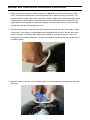
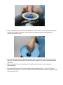
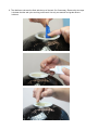
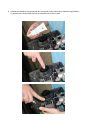
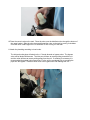
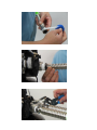
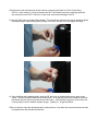
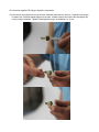
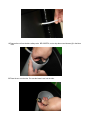
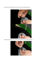
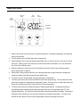
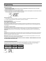
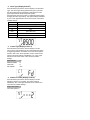
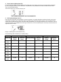
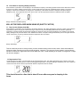
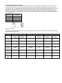
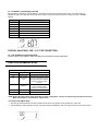
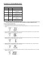
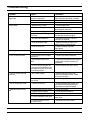
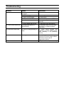
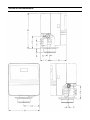
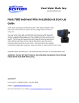
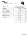
Fusion, Fusion Hybrid and Prelude Water Softener Service Manual IMPORTANT: Fill in Pertinent Information on Page 3 for Future Reference IMPORTANT PLEASE READ: The information, specifications and illustrations in this manual are based on the latest information available at the time of printing. The manufacturer reserves the right to make changes at any time without notice. This manual is intended as a guide for service of the valve only. System installation requires information from a number of suppliers not known at the time of manufacture. This product should be installed by a plumbing professional. This unit is designed to be installed on potable water systems only. This product must be installed in compliance with all state and municipal plumbing and electrical codes. Permits may be required at the time of installation. If daytime operating pressure exceeds 80 psi, nighttime pressures may exceed pressure limits. A pressure reducing valve must be installed. Do not install the unit where temperatures may drop below 32°F (0°C) or above 125°F (52°C). Do not place the unit in direct sunlight. Black units will absorb radiant heat increasing internal temperatures. Do not strike the valve or any of the components. Warranty of this product extends to manufacturing defects. Misapplication of this product may result in failure to properly condition water, or damage to product. A prefilter should be used on installations in which free solids are present. In some applications local municipalities treat water with Chloramines. High Chloramine levels may damage valve components. Correct and constant voltage must be supplied to the control valve to maintain proper function. Job Specification Sheet Job Number: ________________ Model Number: ______________ Water Test: _________________ Capacity Per Unit: ____________ Mineral Tank Size: _________ Diameter: ___________ Height: Brine Tank Size & Salt Setting per Regeneration: _______ 9000/9100/9500 Control Valve Specifications: 1. Type of Timer: A. 82 minute available regeneration time, 1/15 RPM B. 164 minute available regeneration time, 1/30 RPM 2. Type of Meter: Mechanical Valves (Gallon Settings) Meter Standard Range 3/4” 1” 1-1/2” 125 - 2,125 310 - 5,270 625 - 10,625 3. Timer Gallon Setting: 4. Regeneration Program Setting: Extended Range 625 - 10,625 1,150 - 26,350 3,125 - 53,125 Gallons A. Backwash:___________________ Minutes B. Brine and Slow Rinse: _________ Minutes C. Rapid Rinse: _________________ Minutes D. Brine Tank Refill: ______________ Minutes 5. Drain Line Flow Control: __________ gpm 6. Brine Refill Rate: __________________ gpm 7. Injector Size: ____________________ General and Commercial Installation Instructions 1. Place the softener tank where you want to install the unit. NOTE: Be sure the tank is level and on a firm base. The tank base (black plastic) is a floating base that can be adjusted to meet uneven floors. The softener should be located close to the incoming water supply. Irrigation and outside water spigots should be plumbed in prior to the softener. If this cannot be done it is recommended that the softener be in the bypass position during irrigation or watering from a spigot. Grass and other plants do not like soft water and damage to the lawn or landscaping can occur. 2. Check the distributor tube in each tank and make sure they are secured to the tank if the system is using Vortech tanks. If the system is using standard tanks, the distributor will be loose in the tank with a lower basket on the tube. For standard tanks make sure the distributor is centered in the tank. There is an indentation that will center the distributor. The top of the distributor tube will be flush with the tank when it is installed properly. 3. Now place a piece of duct tape over the distributor tube to prevent media from entering the tube during the fill process. 4. Place the supplied funnel in the tank with the distributor tube in the middle. It is recommended that a helper hold the funnel during the fill process. A face shield or eye protection should be used during the fill procedure to prevent an injury. 5. If gravel was shipped with the unit (standard tank large units), pour the gravel in first. Pour the resin in the tank next. The tank should be 60-80% full when the media is installed. Use all the resin that was shipped with the unit. 6. During cold weather it is recommended that the installer warm the valve to room temperature before operating. 7. Perform all plumbing according to local plumbing codes including the drain. — Use a 1/2” minimum pipe/tube size for the drain. — Use a 3/4” drain line for backwash flow rates that exceed 7 gpm or length that exceeds 20’ (6 m). 8. The distributor tube must be flush with the top of the tank. Cut if necessary. Remove the duct tape. Lubricate the tube and nylon seal ring on the tank. Use only non-aerosol food grade silicone lubricant. 9. Lubricate the distributor o-ring seal and tank o-ring seal on the control valve. Install the upper basket by pushing in the slotted holes and turn it clockwise until it locks in place. 10.Place the control valve on the tank. Place the valve over the distributor tube through the bottom of the upper basket. Slide the valve down and thread the valve on the tank by turning it clockwise. Once the valve is hand tight turn it an additional ¼ turn to snug it to the tank. 11.Attach the plumbing according to local codes. The inlet and outlet pipes will attach to the 1” female threads on bypass valve. The bypass valve will be labeled with arrows. The inlet port will have an arrow pointing toward the unit and the outlet will have an arrow pointing away from the unit. If soldering is necessary it is recommended that solder joints closer than 6” to the unit be completed prior to screwing the pipes into the bypass. Excessive heat close to the bypass valve can damage the unit. 12.Solder joints near the drain must be done before connecting the Drain Line Flow Control fitting (DLFC). Leave at least 6” (152 mm) between the DLFC and solder joints when soldering pipes that are connected on the DLFC. Failure to do this could cause interior damage to DLFC. 13.Use only Teflon tape on the drain fitting threads. Two wrenches or channel locks may be needed to tighten the barbed fitting or hard plumbing fitting if tubing is not used. Be sure not to over tighten this fitting. 14. Once the fittings are installed and tight, push the 5/8” drain line on the barb and secure it using a hose clamp. This tube should be attached to a sanitary drain. An air gap fitting should be installed on the drain pipe where this tube will be connected (check local codes). If this is being conveyed to a floor drain, sink or sump pump be sure to maintain a proper air gap. Typically a 1” air gap is sufficient. 15.Be sure the floor under the salt storage tank is clean and level. Any debris can cause a leak when the tank is weighted down with salt and brine solution. 16.Connect the supplied 3/8” tubing to both brine connections. 17.At the control valve place the nut over the tube, install the brass sleeve in the tube. Install the cone screen in brass insert. Install the plastic flange over the tube. Install the tube in the control valve and tighten the nut by turning it clockwise. Tighten it hand tight then snug it an additional ¼ to ½ turn. 18.Remove the white cap from the white tube in the brine tank. Place the other end of the tube through the hole in the side of the bine tank. 19.Remove the nut from the brine safety valve. BE CAREFUL, not to drop the nut and sleeves (2) in the brine tube. 20.Place the nut over the tube. Be sure the brass insert is in the tube. 21.Now place the black split ring on the tube with the coned side facing the nut. 22.Now place the white ring on the tube with the shoulder touching the black split ring. 23.Insert the tube in the brine safety valve elbow and tighten the nut by turning it clock wise. Tighten the nut hand tight and snug it an additional ¼ to ½ turn. Place the white cap back on the white tube. 24.There is a barb fitting on the side of the brine tank. This is used as an overflow and only is used if the brine tank overfills. This barb is for 5/8” tubing. If you elect to use tubing for this elbow, run it to a floor drain or sump pump. 25.Place 3-6 bags of salt in the salt tank. The salt tank is full when the salt level is 1” below the white tube in the brine tank. Pour in 5 gallons of water. The salt should be used then refilled. It is not a good practice to top off the salt weekly. It is better to use it all then refill it. 26.Place the unit in the Bypass position. There is a pointer on the bypass valve handle. This pointer should be pointing to “bypass” on the valve. When the bypass valve is in the bypass position the handle will bisect the plumbing connections. — Turn on the main water supply. — Open a cold soft water tap nearby and let water run a few minutes or until the system is free of foreign material (usually solder) resulting from the installation. Close the water tap when water runs clean. 27.Slowly place the bypass In Service position and let water flow into the mineral tank. Open the bypass in small increments until it is fully open. When water flow stops, slowly open a cold water tap nearby and let water run until air is purged from the unit. Preferably a garden spigot or bath tube. Then close tap once the water runs clear and there is no air in the system. The bypass valve pointer should be pointing toward “service” and the handle should be in line with the plumbing connections. Electrical 28. Make all electrical connections according to codes. Plug the valve into an approved power source. 29. The valve position will be displayed on the control panel. If the unit is in the regeneration process the cycle will be shown on the screen. When the system is in the service position it will display the time of day and flash to the amount of gallons that are remaining before a regeneration of the tank in service is required. TIMER FEATURES Parameter Display Data Display PM Indicator Error/ Information Icon Flow Indicator Service Icon x1000 Indicator Extra Cycle Button Up Button Down Button 1. When in the service mode the service icon will be illuminated. If a delayed regeneration is initiated the service icon will blink. 2. The flow indicator icon will blink when water is being used. 3. When setting the time of day and delayed regeneration time, be sure the clock is in the correct 12 hour time cycle. When you are in the PM time cycle the PM icon will be illuminated. If it is not illuminated the clock is in the AM time cycle. 4. When the display is in the service mode it will flash from the time of day to the remaining capacity before regeneration (in gallons). 5. When water is being used and the flow icon is blinking (water drip on right hand side of display) the remaining capacity value will decrease for each gallon used. 6. The service icon will be illuminated during programming or regeneration. 7. The extra cycle button serves as an enter/return button when programming. The up and down arrows allow value changes in each parameter programming mode. Once the value is reached the extra cycle button can be pushed to save the value and move to the next parameter. 8. The extra cycle button also initiates immediate or delayed regenerations. Pushing and releasing it immediately triggers a delayed regeneration (will regenerate at the time specified under RT in the programming mode). The service icon will blink when a delayed regeneration is initiated. Pushing and holding the extra cycle button for 5 seconds will initiate an immediate regeneration. The service icon will blink and the valve will move to the first regeneration position and begin the process. 9. If the error icon is illuminated there is a problem with the unit and a service technician should be contacted. 10. The x1000 icon will illuminate when values are multiplied by 1000 (capacity setting). 11. The system will hold the values for up to 48 hours after a power outage. Outages exceeding 48 hours should have the programming values revisited. It is a good idea to write down the programming parameters/values so they are available if a reprogramming is required. General and Commercial Installation Checklist WATER PRESSURE: A minimum of 25 pounds of water pressure is required for regeneration valve to operate effectively. ELECTRICAL FACILITIES: A continuous 115 volt, 60 Hertz current supply is required. Make certain the current supply is always energized and cannot be turned off with another switch. EXISTING PLUMBING: Condition of existing plumbing should be free from lime and iron buildup. Piping that is built up heavily with lime and/or iron should be replaced. If piping is clogged with iron, a separate iron filter unit should be installed ahead of the water softener. LOCATION OF SOFTENER AND DRAIN: The softener should be located close to a drain. Programming Setting the Time of Day 1. Press and hold either the Up or Down buttons until the programming icon replaces the service icon and the parameter display reads DO. 2. Adjust the displayed time with the Up and Down buttons. 3. When the desired time is set, press the Extra Cycle button to resume normal operation. The unit will also return to normal operation after 5 seconds if no buttons are pressed. Queuing a Regeneration 1. Press the Extra Cycle button and release. The service icon will flash to indicate that regeneration is queued. 2. To cancel a queued regeneration, press the Extra Cycle button and release. Regenerating Immediately Press and hold the Extra Cycle button for five seconds. Entering Master Programming Mode Set the Time Of Day display to 12:01 P.M. Press the Extra Cycle button (to exit Setting Time of Day mode). Then press and hold the Up and Down buttons together until the programming icon replaces the service icon and the Display Format screen appears. Exiting Master Programming Mode Press the Extra Cycle button to accept the displayed settings and cycle to the next parameter. Press the Extra Cycle button at the last parameter to save all settings and return to normal operation. The control will automatically disregard any programming changes and return to normal operation if it is left in Master Programming mode for 5 minutes without any keypad input. Resets Soft Reset: Press and hold the Extra Cycle and Down buttons for 25 seconds while in normal Service mode. This resets all parameters to the system default values, except the volume remaining in meter immediate or meter delayed systems and days since regeneration in the time clock system. Master Reset: Hold the Extra Cycle button while powering up the unit. This resets all of the parameters in the unit. Check and verify the choices selected in Master Programming Mode. THE HIGHLIGHTED VALUES ARE THE SELECTIONS THAT SHOULD BE MADE. SOME PARAMETERS WILL REFER TO THE SETTINGS CHART FOR VALUES. 1. Display Format (Display Code DF) This is the first screen that appears when entering Master Programming Mode. The Display Format setting specifies the unit of measure that will be used for volume and how the control will display the Time of Day. This option setting is identified by “DF” in the upper left hand corner of the screen. There are three possible settings: Display Format Setting Unit of Volume Time Display GAL U.S. Gallons 12-Hour AM/PM Ltr Liters 24-Hour 2. Valve Type (Display Code VT) Press the Extra Cycle button. Use this display to set the Valve Type. The Valve Type setting specifies the type of cycle that the valve follows during regeneration. Note that some valve types require that the valve be built with specific subcomponents. Ensure the valve is configured properly before changing the Valve Type setting. This option setting is identified by “VT” in the upper left hand corner of the screen. There are 5 possible settings: Abbreviation Parameter dF1b Standard Downflow/Upflow, Single Backwash dF2b Standard Downflow/Upflow, Double Backwash Fltr Filter UFbd Upflow Brine First 8500 TwinFlo 100 Othr Other 3. Control Type (Display Code CT) Press the Extra Cycle button. Use this display to set the Control Type. This specifies how the control determines when to trigger regeneration. For details on how the various options function, refer to the “Timer Operation” section of this service manual. This option setting is identified by “CT” in the upper left hand corner of the screen. There are four possible settings: Meter Delayed: Fd Meter Immediate: FI Time Clock: tc Day of Week: dAY 4. Number of Tanks (Display Code NT) Press the Extra Cycle button. Use this display to set the Number of Tanks in your system. This option setting is identified by “NT” in the upper left hand corner of the screen. There are two possible settings: Single Tank System: 1 Two-Tank System: 2 5. Tank in Service (Display Code TS) Press the Extra Cycle button. Use this display to set whether tank one or tank two is in service. This option setting is identified by “TS” in the upper left hand corner of the screen. This parameter is only available if the number of tanks has been set to 2. There are two possible settings: Tank One in Service: U1 Tank Two in Service: U2 NO CHANGES NECESSARY ON THIS PARAMATER 6. Unit Capacity (Display Code C) Press the Extra Cycle button. Use this display to set the Unit Capacity. This setting specifies the treatment capacity of the system media. Enter the capacity of the media bed in grains of hardness when configuring a softener system, and in the desired volume capacity when configuring a filter system. This option setting is identified by “C” in the upper left hand corner of the screen. The Unit Capacity parameter is only available if the control type has been set to one of the metered options. Use the Up and Down buttons to adjust the value as needed. Range: 1-999,900 gallons (100-9,999,000 Liters) Use the following chart to determine your capacity setting. System Size 26,000 Grain 35,000 Grain 53,000 Grain 70,000 Grain 88,000 Grain 105,000 Grain 140,000 Grain Low Salt Settings Capacity Brine Fill Setting (mins.) 15,000 4 Medium Salt Settings Capacity Setting Brine Fill (mins.) 18,000 6 High Salt Settings Capacity Brine Fill Setting (mins.) 24,000 8 20,000 4 25,000 8 30,000 10 30,000 6 37,000 10 45,000 14 40,000 8 50,000 16 60,000 20 50,000 10 63,000 18 75,000 25 60,000 12 75,000 20 90,000 30 80,000 16 100,000 28 120,000 40 7. Feed Water Hardness (Display Code H) Press the Extra Cycle button. Use this display to set the feed water hardness. Enter the feed water hardness in grains per unit volume for softener systems, or 1 for filter systems. This option setting is identified by “H” in the upper left hand corner of the screen. The feed water hardness parameter is only available if the control type has been set to one of the metered options. Use the Up and Down buttons to adjust the value as needed. Range: 1-199 hardness The hardness level should be set 5 GPG above the actual water feed hardness. The hardness level from the original feed water test will either be expressed in GPG (grains per gallon) or ppm/mg/L (parts per million/milligrams per liter). If the reading is in ppm/mg/L, then divide that value by 17.1 to get GPG. This system only allows hardness inputs in GPG. 8. Reserve Selection (Display Code RS) Press the Extra Cycle button. Use this display to set the Safety Factor. Use this display to select the type of reserve to be used in your system. This setting is identified by “RS” in the upper left-hand corner of the screen. The reserve selection parameter is only available if the control type has been set to one of the metered options. There are two possible settings. 9. SF Safety Factor RC Fixed Reserve Capacity Safety Factor (Display Code SF) Press the Extra Cycle button. Use this display to set the Safety Factor. This setting specifies what percentage of the system capacity will be held as a reserve. Since this value is expressed as a percentage, any change to the unit capacity or feed water hardness that changes the calculated system capacity will result in a corresponding change to the reserve volume. This option setting is identified by “SF” in the upper left hand corner of the screen. Use the Up and Down buttons to adjust the value from 0 to 50% as needed. Add 10% for each member in the home up to 50%. Range: 0-50% 10. Fixed Reserve Capacity (Display Code RC) Press the Extra Cycle button. Use this display to set the Reserve Capacity. This setting specifies a fixed volume that will be held as a reserve. The reserve capacity cannot be set to a value greater than one-half of the calculated system capacity. The reserve capacity is a fixed volume and does not change if the unit capacity or feed water hardness is changed. This option setting is identified by “RC” in the upper left-hand corner of the screen. Use the Up and Down buttons to adjust the value as needed. Range: 0-half the calculated capacity WILL NOT BE DISPLAYED WHEN USING SF (SAFETY FACTOR) 11. Day Override (Display Code DO) Press the Extra Cycle button. Use this display to set the Day Override. This setting specifies the maximum number of days between regeneration cycles. If the system is set to a timer-type control, the day override setting determines how often the system will regenerate. A metered system will regenerate regardless of usage if the days since last regeneration cycle equal the day override setting. Setting the day override value to “OFF” disables this function. This option setting is identified by “DO” in the upper left hand corner of the screen. Use the Up and Down buttons to adjust the value as needed. Range: Off-99 days This will most likely be set at 14 days unless you take vacations lasting more than two weeks. Most households will eclipse the gallon capacity prior to the override engaging. However, if you are gone for two weeks it is a good idea to set this at 10 days so it regenerates and is fresh when you return. Water standing in the system for longer than 14 days can become stagnant. 12. Regeneration Time Press the Extra Cycle button. Use this display to set the Regeneration Time. This setting specifies the time of day the control will initiate a delayed, manually queued, or day override triggered regeneration. This option setting is identified by “RT” in the upper left hand corner of the screen. Use the Up and Down buttons to adjust the value as needed. This should be set to a time that is about 2 hours after everyone is sleeping in the home. 13. Regeneration Cycle Step Times Press the Extra Cycle button. Use this display to set the Regeneration Cycle Step Times. The different regeneration cycles are listed in sequence based on the valve type selected for the system, and are identified by an abbreviation in the upper left-hand corner of the screen. The abbreviations used are listed below. If the system has been configured with the “OTHER” valve type, the regeneration cycles will be identified as R1, R2, R3, R4, R5, and R6. Each cycle step time can be set from 0 to 199 minutes. Setting a cycle step time to 0 will cause the control to skip that step during regeneration, but keeps the following steps available. Use the Up and Down buttons to adjust the value as needed. Press the Extra Cycle button to accept the current setting and move to the next parameter. Cycle Step Abbreviation BW Backwash 10 Mins BD Brine Draw 60 Mins RR Rapid Rinse 10 Mins. BF Brine Fill (see chart) Range: 0-199 minutes This setting is determined by the chart used for the capacity setting. Input the number of minutes that corresponds to the capacity setting that was chose previously. System Size 26,000 Grain 35,000 Grain 53,000 Grain 70,000 Grain 88,000 Grain 105,000 Grain 140,000 Grain Low Salt Settings Capacity Brine Fill Setting (mins.) 15,000 4 Medium Salt Settings Capacity Setting Brine Fill (mins.) 18,000 6 High Salt Settings Capacity Brine Fill Setting (mins.) 24,000 8 20,000 4 25,000 8 30,000 10 30,000 6 37,000 10 45,000 14 40,000 8 50,000 16 60,000 20 50,000 10 63,000 18 75,000 25 60,000 12 75,000 20 90,000 30 80,000 16 100,000 28 120,000 40 14. Flow Meter Type (Display Code FM) Press the Extra Cycle button. Use this display to set the type of flow meter connected to the control. This option setting is identified by “FM” in the upper left-hand corner of the screen. Use the Up and Down buttons to select one of the 7 available settings. t0.7 Fleck 3/4” Turbine Meter P0.7 Fleck 3/4” Paddle Wheel Meter t1.0 Fleck 1” Turbine Meter P1.0 Fleck 1” Paddle Wheel Meter t1.5 Fleck 1 1/2” Turbine Meter P1.5 Fleck 1 1/2” Paddle Wheel Meter P2.0 Fleck 2” Paddle Wheel Meter GEn Generic/Other Meter THE 9500 VALVE WILL USE “t1.5” FOR THIS SETTING. 15. End of Master Programming Mode Press the Extra Cycle button to save all settings and exit Master Programming Mode USER PROGRAMMING MODE User Programming Mode Options Abbreviation Parameter Description DO Day Override The timer’s day override setting RT Regeneration Time The time of day that the system will regenerate (meter delayed, timeclock, and day-of-week systems) H Feed Water Hardness The hardness of the inlet water - used to calculate system capacity for metered systems RC or SF Reserve Capacity The fixed reserve capacity CD Current Day The current day of week NOTE: Some items may not be shown depending on timer configuration. The timer will discard any changes and exit User Mode if any button is not pressed for sixty seconds. User Programming Mode Steps 1. Press the Up and Down buttons for five seconds while in service, and the time of day is NOT set to 12:01 PM. 2. Use this display to adjust the Day Override. This option setting is identified by “DO” in the upper left hand corner of the screen. 3. Press the Extra Cycle button. Use this display to adjust the Regeneration Time. This option setting is identified by “RT” in the upper left hand corner of the screen. 4. Press the Extra Cycle button. Use this display to adjust the Feed Water Hardness. This option setting is identified by “H” in the upper left hand corner of the screen. Range: 1-199 hardness 5. Press the Extra Cycle button. Use this display to adjust the Fixed Reserve Capacity. This option setting is identified by “RC” or "SF" in the upper left-hand Corner of the screen. 6. Press the Extra Cycle button. Use this display to set the Current Day of the Week. This option setting is identified by “CD” in the upper left hand corner of the screen. 7. Press the Extra Cycle button to end User Programming Mode. DIAGNOSTIC PROGRAMMING MODE Diagnostic Programming Mode Options Abbreviation Parameter Description FR Flow Rate Displays the current outlet flow rate PF Peak Flow Rate Displays the highest flow rate measured since the last regeneration HR Hours in Service Displays the total hours that the unit has been in service VU Volume Used Displays the total volume of water treated by the unit RC Reserve Capacity Displays the system’s reserve capacity calculated from the system capacity, feedwater hardness, and safety factor SV Software Version Displays the software version installed on the controller NOTE: Some items may not be shown depending on timer configuration. The timer will exit Diagnostic Mode after 60 seconds if no buttons are pressed. Press the Extra Cycle button to exit Diagnostic Mode at any time. Diagnostic Programming Mode Steps 1. Press the Up and Extra Cycle buttons for five seconds while in service. 2. Use this display to view the current Flow Rate. This option setting is identified by “FR” in the upper left hand corner of the screen. 3. Press the Up button. Use this display to view the Peak Flow Rate since the last regeneration cycle. This option setting is identified by “PF” in the upper left hand corner of the screen. 4. Press the Up button. Use this display to view the Hours in Service since the last regeneration cycle. This option setting is identified by “HR” in the upper left hand corner of the screen. 5. Press the Up button. Use this display to view the Volume Used since the last regeneration cycle. This option setting is identified by “VU” in the upper left hand corner of the screen. 6. Press the Up button. Use this display to view the Reserve Capacity. This option setting is identified by “RC” in the upper left hand corner of the screen. 7. Press the Up button. Use this display to view the Software Version. This option setting is identified by “SV” in the upper left hand corner of the screen. Press the Extra Cycle button to end Diagnostic Programming Mode. Troubleshooting Problem Cause Correction 1. Water conditioner fails to regenerate. A. Electrical service to unit has been interrupted B. Control is defective. C. Power failure. A. By-pass valve is open. B. No salt is in brine tank. A. Assure permanent electrical service (check fuse, plug, pull chain, or switch) B. Replace Control. C. Reset time of day. A. Close by-pass valve. B. Add salt to brine tank and maintain salt level above water level. C. Clean injector screen. D. Check brine tank fill time and clean brine line flow control if plugged. E. Repeated flushings of the hot water tank is required. F. Make sure distributor tube is not cracked. Check O-ring and tube pilot. G. Replace seals and spacers and/or piston. A. Check salt usage and salt setting. B. See problem 7. A. Clean line to water conditioner. 2. Hard water. C. Injector screen plugged. D. Insufficient water flowing into brine tank. E. Hot water tank hardness. F. Leak at distributor tube. G. Internal valve leak. 3. Unit used too much salt. 4. Loss of water pressure. 5. Loss of mineral through drain line. 6. Iron in conditioned water. 7. Excessive water in brine tank. A. Improper salt setting. B. Excessive water in brine tank. A. Iron buildup in line to water conditioner. B. Iron buildup in water conditioner. C. Inlet of control plugged due to foreign material broken loose from pipes by recent work done on plumbing system. A. Air in water system. B. Improperly sized drain line flow control. A. Fouled mineral bed. A. Plugged drain line flow control. B. Plugged injector system. C. Timer not cycling. D. Foreign material in brine valve. E. Foreign material in brine line flow control. B. Clean control and add mineral cleaner to mineral bed. Increase frequency of regeneration. C. Remove piston and clean control. A. Assure that well system has proper air eliminator control. Check for dry well condition. B. Check for proper drain rate. A. Check backwash, brine draw, and brine tank fill. Increase frequency of regeneration. Increase backwash time. A. Clean flow control. B. Clean injector and screen. C. Replace timer. D. Replace brine valve seat and clean valve. E. Clean brine line flow control. Troubleshooting Problem Cause Correction 8. Softener fails to draw brine. A. Drain line flow control is plugged. B. Injector is plugged. C. Injector screen plugged. D. Line pressure is too low. E. Internal control leak A. Clean drain line flow control. B. Foreign material in control. B. Remove power head assembly and inspect bore. Remove foreign material and check control in various regeneration positions. C. Replace seals and piston assembly. 9. Control cycles continuously. 10. Drain flows continuously. B. Clean injector C. Clean screen. D. Increase line pressure to 20 P.S.I. E. Change seals, spacers, and piston assembly. F. Service adapter did not cycle. F. Check drive motor and switches. A. Misadjusted, broken, or A. Determine if switch or timer is faulty shorted switch. and replace it, or replace complete power head. A. Valve is not programming cor- A. Check control program and rectly. positioning of control. Replace power head assembly if not positioning properly. C. Internal control leak. Control Dimensions NOTES