1
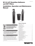
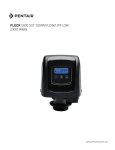
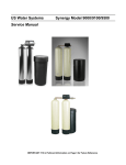
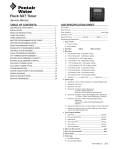
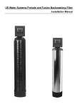
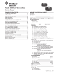
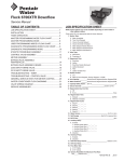
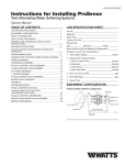
Fleck 5800 LXT & SXT Downflow/Upflow
Service Manual
TABLE OF CONTENTS
JOB SPECIFICATION SHEET................................................1
INSTALLATION.......................................................................2
START-UP INSTRUCTIONS...................................................3
TIMER FEATURES.................................................................3
TIMER OPERATION...............................................................4
MASTER PROGRAMMING MODE.........................................5
DIAGNOSTIC PROGRAMMING MODE.................................6
POWERHEAD ASSEMBLY.....................................................7
5800 CONTROL VALVE ASSEMBLY
DOWNFLOW/UPFLOW..........................................................8
3/4" PLASTIC TURBINE METER ASSEMBLY.......................9
METER ASSEMBLY................................................................9
3/4", 1" or 1-1/2" PADDLE WHEEL
METER CAP ASSEMBLY........................................................10
BYPASS VALVE ASSEMBLY (PLASTIC)................................10
BYPASS VALVE ASSEMBLY (PLASTIC)................................11
2310 SAFETY BRINE VALVE.................................................11
WATER CONDITIONER FLOW DIAGRAMS..........................12
TROUBLESHOOTING............................................................14
The chart below is for dealer use only. Use this information
to configure the system to suit the application. The 5800 LXT
timer will use the settings to calculate cycle times.
Tank
Diameter
8
Resin Volume
BLFC Size
Metric
(Liters)
0.75
20
#000
0.125
25
#000
0.125
9
9
1.00
30
#000
0.125
10
1.25
35
#00
0.125
10
1.50
40
#00
0.125
45
#00
0.125
12
12
1.75
50
#00
0.125
12
2.00
55
#0
0.25
60
#0
0.25
13
13
2.25
65
#0
0.25
14
2.50
70
#1
0.25
14
75
#1
0.25
14
2.75
80
#1
0.25
14
3.00
85
#1
0.25
14
3.25
90
#2
0.50
95
#2
0.50
14
3.50
100
#2
0.50
16
3.75
105
#3
0.50
110
#3
0.50
115
#3
0.50
14
16
16
Injector
Size
US (FT )
3
4.00
43359 Rev A
MR12
JOB SPECIFICATION SHEET
Job Number:_ ___________________________________________________
Model Number:_ _________________________________________________
Water Hardness: ________________________________________ ppm or gpg
Capacity Per Unit:________________________________________________
Mineral Tank Size:_______________ Diameter:_ ________ Height:__________
Salt Setting per Regeneration:_ _____________________________________
Regenerant Flow:
Upflow
Downflow
1. Meter Size:
A. 3/4" Paddle Wheel (Not Used)
B. 3/4" Turbine
C. 1" Paddle Wheel (Not Used)
D. 1" Turbine (Not Used)
E. 1-1/2" Electronic Inline Plastic Turbine (Not Used)
F. 1-1/2" Paddle Wheel (Not Used)
G. 2" Paddle Wheel (Not Used)
H. Generic_________Pulse Count__________Meter Size__________
2. System Type:
A. System #4: 1 Tank, 1 Meter, Immediate, or Delayed Regeneration
B. System #4: Time Clock
3. Timer Program Settings:
A. Backwash:____________________________________ Minutes
B. Brine and Slow Rinse:___________________________ Minutes
C. Rapid Rinse:_ _________________________________ Minutes
D. Brine Tank Refill:_______________________________ Minutes
E. Pause Time:___________________________________ Minutes
F. Second Backwash:_ ____________________________ Minutes
4. Drain Line Flow Control:_ ______________________________gpm
5. Brine Line Flow Control:_ ______________________________gpm
6. Injector Size#: _____________________________________________
2 • MR12 Fleck 5800 LXT & SXT Downflow/Upflow
INSTALLATION
Water Pressure
A minimum of 20 pounds (1.4 bar) of water pressure is required
for the regeneration valve to operate effectively.
Electrical Facilities
An uninterrupted alternating current (120 VAC) supply is
required. The control uses a tranformer to supply 12 VDC.
Please make sure your voltage supply is compatible with your
unit before installation.
Existing Plumbing
Condition of existing plumbing should be free from lime and
iron buildup. Piping that is built up heavily with lime and/or iron
should be replaced. If piping is clogged with iron, a separate
iron filter unit should be installed ahead of the water softener.
Location Of Softener And Drain
The softener should be located close to a drain to prevent air
breaks and back flow.
CAUTION If grid plate is used, cut air check height even
with grid plate. This is critical on 6", 7", 8" and 9"
tanks. The brine refill water must come above the
grid plate and make contact with the salt.
10.On units with a by-pass, place in by-pass position. Turn on
the main water supply. Open a cold soft water tap nearby
and let run a few minutes or until the plumbing is free from
foreign material (usually solder) that may have resulted
from the installation. Once clean, close the water tap.
11.Slowly place the by-pass in service position and let water
flow into the mineral tank. When water flow stops, slowly
open a cold water tap nearby and let water run until the air
is purged from the unit.
12.Plug the transformer into an electrical outlet.
NOTE: All electrical connections must be connected
according to local codes. Be certain the outlet is
uninterrupted.
By-Pass Valves
Always provide for the installation of a by-pass valve if unit is
not equipped with one.
CAUTION Water pressure is not to exceed 125 psi (8.6 bar),
water temperature is not to exceed 110°F (43°C),
and the unit cannot be subjected to freezing
conditions.
WARNING: The system must be depressurized before
removing any connections for servicing.
Installation Instructions
1. Place the softener tank where you want to install the unit.
make sure the unit is level and on a firm base.
2. During cold weather, the installer should warm the valve to
room temperature before operating.
3. All plumbing should be done in accordance with local
plumbing codes. The pipe size for a residential drain line
should be a minimum of 1/2" (13 mm). Backwash flow rates
in excess of 7 gpm (26.5 Lpm) or drain line length in excess
of 20' (6 m) require 3/4" (19 mm) drain line. Commercial
drain lines should be the same size as the drain line flow
control.
NOTE: The tank should have the distributor tube installed
and have the proper amount of regenerant in place.
4. Refer to the dimensional drawing for cutting height of the
distributor tube. If there is no dimensional drawing, cut the
distributor tube flush with the top of the tank.
5. Lubricate the distributor O-ring seal and tank O-ring seal.
Place the main control valve on tank. Note: Only use
silicone lubricant.
6. Soldering of joints near the drain port must be done prior
to connecting the Drain Line Flow Control fitting (DLFC).
Leave at least 6" (15 cm) between the DLFC and solder
joints when soldering pipes that are connected on the
DLFC. Failure to do this could cause interior damage to the
DLFC.
7. PTFE plumbing tape is the only sealant to be used on the
drain fitting.
8. Make sure that the floor is clean beneath the salt storage
tank and that the tank is level.
9. Place approximately 1" (25 mm) of water above the grid
plate. If a grid is not utilized, fill to the top of the air check
(Figure 1) in the salt tank. Do not add salt to the brine tank
at this time.
60002 Rev E
Figure 1 Residential Air Check Valve
Fleck 5800 LXT & SXT Downflow/Upflow MR12 • 3
START-UP INSTRUCTIONS LXT
The water softener should be installed with the inlet, outlet, and
drain connections made in accordance with the manufacturer’s
recommendations, and to meet applicable plumbing codes.
1. Program the valve control according to instructions shown
in this manual.
2. Start an immediate regeneration by holding the Extra Cycle
button for 5 seconds. Position the valve to backwash.
Ensure the drain line flow remains steady for 10 minutes or
until the water runs clear.
3. Position the valve to the brine / slow rinse position. Ensure
the unit is drawing water from the brine tank (this step may
need to be repeated).
4. Position the valve to the rapid rinse position. Check the
drain line flow, and run for 5 minutes or until the water runs
clear.
5. Position the valve to the start of the brine tank fill cycle.
Ensure water goes into the brine tank at the desired rate.
The brine valve drive cam will hold the valve in this position
to fill the brine tank for the first regeneration.
6. Replace control cover.
7. Put salt in the brine tank.
NOTE: Do not use granulated or rock salt.
TIMER FEATURES LXT
Program Icon
Display Position
Clock
Service Indicator
Time of
Day
Filter
Capacity
PM
Time of
Backwash
Backwash
Length
Flow
Indicator
Capacity
Remaining
Resin
MODE
Mode
Button
Extra Cycle
Button
Figure 2
Features of the LXT:
• Power backup that continues to keep time and the
passage of days for a minimum of 12 hours in the event
of power failure. During a power outage, the control goes
into a power-saving mode. It does not monitor water
usage during a power failure, but it does store the volume
remaining at the time of power failure.
• Day of the week reserve calculates a reserve for each
day based on the past 4 weeks.
• The Flow Indicator flashes when outlet flow is detected.
• The Service Icon flashes if a regeneration cycle has been
queued.
• A Regeneration can be triggered immediately by pressing
the Extra Cycle button for five seconds.
• During a regeneration, the display will show the cycle
number followed by the time remaining in that cycle
• During regeneration, the user can force the control to
advance to the next cycle step immediately by pressing
the extra cycle button.
Time
Remaining
Cycle
Figure 3
Setting the Time of Day
1. Press and hold either the Up or Down buttons until the Time
of Day icon appears.
2. Adjust the displayed time with the Up and Down buttons.
3. When the desired time is set, press the Extra Cycle button
to resume normal operation. The unit will also return to
normal operation after 5 seconds if no buttons are pressed.
PM
Figure 4
Queueing a Regeneration
1. Press the Extra Cycle button. The service icon will flash to
indicate that a regeneration is queued.
2. To cancel a queued regeneration, press the Extra Cycle
button.
4 • MR12 Fleck 5800 LXT & SXT Downflow/Upflow
Regenerating Immediately
Press and hold the Extra Cycle button for five seconds.
TIMER OPERATION LXT
Meter Delayed Control
A Meter Delayed Control measures water usage. The system
regenerates at the programmed regeneration time after the
calculated system capacity is depleted. The control calculates
the system capacity by dividing the unit capacity by the
feedwater hardness and subtracting the reserve. The reserve
should be set to insure that the system delivers treated water
between the time the system capacity is depleted and the
actual regeneration time. A Meter Delayed control will also start
a regeneration cycle at the programmed regeneration time if
a number of days equal to the regeneration day override pass
before water usage depletes the calculated system capacity.
Control Operation During Regeneration
During regeneration, the control displays a special
regeneration display. In this display, the control shows the
current regeneration step number the valve is advancing to,
or has reached, and the time remaining in that step. The step
number that displays flashes until the valve completes driving
to this regeneration step position. Once all regeneration steps
are complete the valve returns to service and resumes normal
operation.
The meter and time clock controls will use and display cycles:
1. Backwash
2. Brine/Slow Rinse
3. Rapid Rinse
4. Brine Tank Refill
The filter controls will use and display cycles:
1. Backwash
2. Rapid Rinse
Pressing the Extra Cycle button during a regeneration cycle
immediately advances the valve to the next cycle step position
and resumes normal step timing.
Control Operation During A Power Failure
The LXT includes integral power backup. In the event of power
failure, the control shifts into a power-saving mode. The control
stops monitoring water usage. The display and motor shut
down, but it continues to keep track of the time and day for a
minimum of 12 hours.
The system configuration settings are stored in a non-volatile
memory and are stored indefinitely with or without line power.
If power fails while the unit is in regeneration, the control will
save the current valve position before it shuts down. When
power is restored, the control will resume the regeneration
cycle from the point where power failed.
CAUTION If power fails during a regeneration cycle, the
valve will remain in it’s current position until
power is restored. The valve system should
include all required safety components to
prevent overflows resulting from a power failure
during regeneration.
The control will not start a new regeneration cycle without line
power. If the valve misses a scheduled regeneration due to
a power failure, it will queue a regeneration. Once power is
restored, the control will initiate a regeneration cycle the next
time that the Time of Day equals the programmed regeneration
time. Typically, this means that the valve will regenerate one
day after it was originally scheduled. If the treated water
output is important and power interruptions are expected, the
system should be setup with a sufficient reserve capacity to
compensate for regeneration delays.
Control Operation During Programming
The control only enters the Program Mode with the valve in
service. While in the Program Mode, the control continues
to operate normally monitoring water usage and keeping all
displays up to date. Control programming is stored in memory
permanently, and does not rely on battery backup power.
Manually Initiating a Regeneration
1. When timer is in service, press the Extra Cycle button for 5
seconds on the main screen.
2. The timer advances to Regeneration Cycle Step #1
(backwash), and begins programmed time count down.
3. Press the Extra Cycle button once to advance valve to
Regeneration Cycle Step #2 (brine draw & slow rinse).
4. Press the Extra Cycle button once to advance valve to
Regeneration Cycle Step #3 (rapid rinse).
5. Press the Extra Cycle button once to advance valve to
Regeneration Cycle Step #4 (brine refill).
6. Press the Extra Cycle button once more to advance the
valve back to in service.
NOTE: If the unit is a filter or upflow, the cycle step
order may change.
NOTE: A queued regeneration can be initiated by
pressing the Extra Cycle button. To clear a
queued regeneration, press the Extra Cycle
button again to cancel. If regeneration occurs for
any reason prior to the delayed regeneration time,
the manual regeneration request will be cleared.
Fleck 5800 LXT & SXT Downflow/Upflow MR12 • 5
START-UP INSTRUCTIONS SXT
The water softener should be installed with the inlet, outlet, and
drain connections made in accordance with the manufacturer’s
recommendations, and to meet applicable plumbing codes.
1. Program the valve control according to instructions shown
in this manual.
2. Start an immediate regeneration by holding the Extra Cycle
button for 5 seconds. Position the valve to backwash.
Ensure the drain line flow remains steady for 10 minutes or
until the water runs clear.
3. Position the valve to the brine / slow rinse position. Ensure
the unit is drawing water from the brine tank (this step may
need to be repeated).
4. Position the valve to the rapid rinse position. Check the
drain line flow, and run for 5 minutes or until the water runs
clear.
5. Position the valve to the start of the brine tank fill cycle.
Ensure water goes into the brine tank at the desired rate.
The brine valve drive cam will hold the valve in this position
to fill the brine tank for the first regeneration.
6. Replace control cover.
7. Put salt in the brine tank.
NOTE: Do not use granulated or rock salt.
• The Parameter Display displays the current Cycle Step
(BW, BF, RR etc) during regeneration, and the data
display counts down the time remaining for that cycle
step. While the valve is transferring to a new cycle step,
the display will flash. The parameter display will identify
the destination cycle step (BW, BF, RR, etc) and the data
display will read "------". Once the valve reaches the cycle
step, the display will stop flashing and the data display
will change to the time remaining. During regeneration,
the user can force the control to advance to the next cycle
step immediately by pressing the extra cycle button.
Setting the Time of Day
1. Press and hold either the Up or Down buttons until the
programming icon replaces the service icon and the
parameter display reads TD.
2. Adjust the displayed time with the Up and Down buttons.
3. When the desired time is set, press the Extra Cycle button
to resume normal operation. The unit will also return to
normal operation after 5 seconds if no buttons are pressed.
TIMER FEATURES SXT
Figure 6
Queueing a Regeneration
1. Press the Extra Cycle button. The service icon will flash to
indicate that a regeneration is queued.
2. To cancel a queued regeneration, press the Extra Cycle
button.
Regenerating Immediately
Press and hold the Extra Cycle button for five seconds.
Figure 5
Features of the SXT:
• Power backup that continues to keep time and the
passage of days for a minimum of 48 hours in the event
of power failure. During a power outage, the control goes
into a power-saving mode. It does not monitor water
usage during a power failure, but it does store the volume
remaining at the time of power failure.
• Settings for both valve (basic system) and control type
(method used to trigger a regeneration).
• Day-of-the-Week controls.
• While in service, the display alternates between time of
day, volume remaining or days to regeneration.
• The Flow Indicator flashes when outlet flow is detected.
• The Service Icon flashes if a regeneration cycle has been
queued.
• A Regeneration can be triggered immediately by pressing
the Extra Cycle button for five seconds.
6 • MR12 Fleck 5800 LXT & SXT Downflow/Upflow
TIMER OPERATION SXT
Meter Immediate Control
A Meter Immediate control measures water usage and
regenerates the system as soon as the calculated system
capacity is depleted. The control calculates the system
capacity by dividing the unit capacity (typically expressed in
grains/unit volume) by the feedwater hardness and subtracting
the reserve. Meter Immediate systems generally do not use
a reserve volume. The control will also start a regeneration
cycle at the programmed regeneration time if a number of days
equal to the regeneratio day override pass before water usage
depletes the calculated system capacity.
Meter Delayed Control
A Meter Delayed Control measures water usage. The system
regenerates at the programmed regeneration time after
the calculated system capacity is depleted. As with Meter
Immediate systems, the control calculates the system capacity
by dividing the unit capacity by the feedwater hardness and
subtracting the reserve. The reserve should be set to insure
that the system delivers treated water between the time the
system capacity is depleted and the actual regeneration time. A
Meter Delayed control will also start a regeneration cycle at the
programmed regeneration time if a number of days equal to the
regeneration day override pass before water usage depletes
the calculated system capacity.
Time Clock Delayed Control
A Time Clock Delayed Control regenerates the system on a
timed interval. The control will initiate a regeneration cycle
at the programmed regeneration time when the number of
days since the last regeneration equals the regeneration day
override value.
Day of the Week Control
This control regenerates the system on a weekly schedule. The
schedule is defined in Master programming by setting each
day to either "off" or "on". The control will initiate a regeneration
cycle on days that have been set to "on" at the specified
regeneration time.
Control Operation During Regeneration
During regeneration, the control displays a special
regeneration display. In this display, the control shows the
current regeneration step number the valve is advancing to,
or has reached, and the time remaining in that step. The step
number that displays flashes until the valve completes driving
to this regeneration step position. Once all regeneration steps
are complete the valve returns to service and resumes normal
operation.
Pressing the Extra Cycle button during a regeneration cycle
immediately advances the valve to the next cycle step position
and resumes normal step timing.
Regeneration Cycle Step #2 (backwash).
4. Press the Extra Cycle button once to advance valve to
Regeneration Cycle Step #3 (brine draw & slow rinse).
5. Press the Extra Cycle button once to advance valve to
Regeneration Cycle Step #4 (brine refill).
6. Press the Extra Cycle button once more to advance the
valve back to in service.
NOTE: If the unit is a filter or upflow, the cycle step
order may change.
NOTE: A queued regeneration can be initiated by
pressing the Extra Cycle button. To clear a
queued regeneration, press the Extra Cycle
button again to cancel. If regeneration occurs for
any reason prior to the delayed regeneration time,
the manual regeneration request will be cleared.
Control Operation During A Power Failure
The SXT includes integral power backup. In the event of power
failure, the control shifts into a power-saving mode. The control
stops monitoring water usage. The display and motor shut
down, but it continues to keep track of the time and day for a
minimum of 12 hours.
The system configuration settings are stored in a non-volatile
memory and are stored indefinitely with or without power. The
Time of Day flashes when there has been a power failure.
Press any button to stop the Time of Day from flashing.
If power fails while the unit is in regeneration, the control will
save the current valve position before it shuts down. When
power is restored, the control will resume the regeneration
cycle from the point where power failed.
CAUTION If power fails during a regeneration cycle, the
valve will remain in it’s current position until
power is restored. The valve system should
include all required safety components to
prevent overflows resulting from a power failure
during regeneration.
The control will not start a new regeneration cycle without
power. If the valve misses a scheduled regeneration due to
a power failure, it will queue a regeneration. Once power is
restored, the control will initiate a regeneration cycle the next
time that the Time of Day equals the programmed regeneration
time. Typically, this means that the valve will regenerate one
day after it was originally scheduled. If the treated water
output is important and power interruptions are expected, the
system should be setup with a sufficient reserve capacity to
compensate for regeneration delays.
Control Operation During Programming
The control only enters the Program Mode with the valve in
service. While in the Program Mode, the control continues
to operate normally monitoring water usage and keeping all
displays up to date. Control programming is stored in memory
permanently.
Manually Initiating a Regeneration
1. When timer is in service, press the Extra Cycle button for 5
seconds on the main screen.
2. The timer advances to Regeneration Cycle Step #1 (rapid
rinse), and begins programmed time count down.
3. Press the Extra Cycle button once to advance valve to
Fleck 5800 LXT & SXT Downflow/Upflow MR12 • 7
Time of
Day
Filter
Capacity
MASTER PROGRAMMING MODE LXT
PM
Time of
Backwash
Capacity
Remaining
Backwash
Resin
CAUTION Before
Length entering Master Programming, please
contact your local professional water dealer.
Time of
Day
MODE
Mode
Button
Time of
Regen
Up
Arrow
Down
Arrow
Extra Cycle
Button
Figure 7
Press Mode button to cycle through programming options.
When timer is powered up, the display position will point to
Time of Day. Set time of day by holding the Up or Down arrow.
Hold the Extra Cycle button until the Program icon disappears
to save the current time.
5800 Meter Downflow/Upflow
Time of
Day
Time of
Regen
Salt
Amount
5800 Time Clock Downflow/Upflow
Hardness
PM
Capacity
Remaining
Resin
MODE
Figure 8
1. Press the Mode button to advance to Time of Regen. Push
the Up or Down arrow to adjust the time of regeneration.
2. Press the Mode button again to advance to Salt Amount.
Press the Up or Down arrow to adjust your salt dosage.
English timer range is 3-18 lbs. Metric timer range is 50-290
grams per liter.
3. Press the Mode button again to advance to Hardness.
Press the Up or Down arrow to adjust the setting to your
hardness. English timer range is 3 to 200 gpg. Metric timer
range is 30-200 mgl.
4. Press the Mode button again to advance to Capacity
Remaining. This is the amount of gallons the unit can treat.
This is not adjustable.
5. Press the Mode button again to advance to Resin. Use the
Up or Down arrow to adjust the amount of CuFt resin in
your tank. English timer range is 0.25-3.0 CuFt. Metric timer
range is 5-100 liters.
6. Hold the Extra Cycle button until the Program icon
disappears to save your programming.
7. If you are just changing one program step, hold the Extra
Cycle button until the Program icon disappears to save your
changes. If you do not hold the Extra Cycle button until the
Program icon disappears your changes will not be saved.
NOTE: This unit has a day of the week reserve. It
calculates a reserve for each day of the week based
on the past 4 weeks.
8 • MR12 Fleck 5800 LXT & SXT Downflow/Upflow
Salt
Amount
PM
Days
Between
Regens
Days to
Regen
Resin
MODE
Figure 9
1. Press the Mode button to advance to Time of Regen. Push
the Up or Down arrow to adjust the time of regeneration.
2. Press the Mode button again to advance to Salt Amount.
Press the Up or Down arrow to adjust your salt dosage.
English timer range is 3-18 lbs. Metric timer range is 50-290
grams per liter.
3. Press the Mode button again to advance to Days Between
Regens. Range is 1 to 30 days.
4. Press the Mode button again to advance to Days to Regen.
This is not adjustable.
5. Press the Mode button again to advance to Resin. Use the
Up or Down arrow to adjust the amount of CuFt resin in
your tank. English timer range is 0.25-3.0 CuFt. Metric timer
range is 5-100 liters.
6. Hold the Extra Cycle button until the Program icon
disappears to save your programming.
7. If you are just changing one program step, hold the Extra
Cycle button until the Program icon disappears to save your
changes. If you do not hold the Extra Cycle button until the
Program icon disappears your changes will not be saved.
MASTER PROGRAMMING MODE LXT
continued
5800 Filter Meter
Filter
Capacity
Time of
Day
Time of
Backwash
Backwash
Length
PM
Capacity
Remaining
Resin
MODE
Figure 10
1. Press the Mode button to advance to Time of Backwash.
Push the Up or Down arrow to adjust the time of backwash.
2. Press the Mode button again to advance to Backwash
Length. Press the Up or Down arrow to adjust your
backwash length. Range is 1-30 minutes.
3. Press the Mode button again to advance to Filter Capacity.
Press the Up or Down arrow to adjust the setting for filter
capacity. English timer range is 100-90,000 gallons. Metric
timer range is 1-900 cubic meters.
4. Press the Mode button again to advance to Capacity
Remaining. This is not adjustable.
5. Press the Mode button again to advance to Resin. Use the
Up or Down arrow to adjust the amount of CuFt resin in
your tank. English timer range is 0.25-3.0 CuFt. Metric timer
range is 5-100 liters.
6. Hold the Extra Cycle button until the Program icon
disappears to save your programming.
7. If you are just changing one program step, hold the Extra
Cycle button until the Program icon disappears to save your
changes. If you do not hold the Extra Cycle button until the
Program icon disappears your changes will not be saved.
NOTE: This unit has a day of the week reserve. It
calculates a reserve for each day of the week based
on the past 4 weeks.
5800 Filter Time Clock
Time of
Day
Time of
Backwash
Backwash
Length
PM
Days
Between
Regens
Days to
Backwash
Resin
MODE
Figure 11
1. Press the Mode button to advance to Time of Backwash.
Push the Up or Down arrow to adjust the time of backwash.
2. Press the Mode button again to advance to Backwash
Length. Press the Up or Down arrow to adjust your
backwash length. Range is 1-30 minutes.
3. Press the Mode button again to advance to Days Between
Regens. Range is 1 to 30 days.
4. Press the Mode button again to advance to Days to
Backwash. This is not adjustable.
5. Press the Mode button again to advance to Resin. Use the
Up or Down arrow to adjust the amount of CuFt resin in
your tank. English timer range is 0.25-3.0 CuFt. Metric timer
range is 5-100 liters.
6. Hold the Extra Cycle button until the Program icon
disappears to save your programming.
7. If you are just changing one program step, hold the Extra
Cycle button until the Program icon disappears to save your
changes. If you do not hold the Extra Cycle button until the
Program icon disappears your changes will not be saved.
Fleck 5800 LXT & SXT Downflow/Upflow MR12 • 9
DIAGNOSTIC PROGRAMMING MODE
LXT
Demand - US Units
Diagnostic
Code
Description
H1
Displays the days since last regeneration, 0-30.
H2
Displays the current flow rate, gallons per minute.
H3
Displays the current day of week, 1-7.
H4
Displays the total volume of water treated by the unit
for the current day in gallons.
H5
Displays the total volume of water used since the last
regeneration in gallons.
H6
Displays the software version. Version number of
software. D = Downflow U = Upflow
A1
Displays the average water usage for day 1,
in gallons.
A2
Displays the average water usage for day 2,
in gallons.
A3
Displays the average water usage for day 3,
in gallons.
A4
Displays the average water usage for day 4,
in gallons.
A5
Displays the average water usage for day 5,
in gallons.
A6
Displays the average water usage for day 6,
in gallons.
A7
Displays the average water usage for day 7,
in gallons.
Demand - Metric Units
Diagnostic
Code
Description
H1
Displays the days since last regeneration, 0-30.
H2
Displays the current flow rate, liters per minute.
H3
Displays the current day of week.
H4
Displays the total volume of water treated by the unit
for the current day, in cubic meters.
H5
Displays the total volume of water used since the last
regeneration, in cubic meters.
H6
Displays the software version. Version number of
software. D = Downflow U = Upflow
A1
Displays the average water usage for day 1,
in cubic meters.
A2
Displays the average water usage for day 2,
in cubic meters.
A3
Displays the average water usage for day 3,
in cubic meters.
A4
Displays the average water usage for day 4,
in cubic meters.
A5
Displays the average water usage for day 5,
in cubic meters.
A6
Displays the average water usage for day 6,
in cubic meters.
A7
Displays the average water usage for day 7,
in cubic meters.
10 • MR12 Fleck 5800 LXT & SXT Downflow/Upflow
Time Clock
Diagnostic
Code
Description
H1
Displays the days since last regeneration, 1-7.
H6
Displays the software version. Version number of
software. D = Downflow U=
Upflow
Filter
Time of
Day
Capacity
PM
Time of
Backwash
NOTE: The Engilsh timer will be in gallons. Capacity
The Metric
Remaining
timer
will be in liters for all flow rates.
Backwash
Resin
Length
Diagnostic Programming Mode Steps
MODE
Mode
Button
Up
Arrow
Down
Arrow
Extra Cycle
Button
Figure 12
1. To enter the Diagnostic Programming Mode, press and hold
the Mode button and the Up arrow.
2. The display will show the first diagnostic. Press the Up
arrow to view the value.
3. Press the Mode button twice to move to the next diagnostic.
4. Press the Up arrow to view the value. Continue in this
manner until you have viewed all the diagnostics. The table
above shows all the diagnostics.
5. To exit Diagnostic Programming Mode, hold the Extra Cycle
button for one minute. It will also exit after 30 seconds if no
button is pushed.
MASTER PROGRAMMING MODE
CHART SXT
CAUTION Before entering Master Programming, please
contact your local professional water dealer.
Master Programming Options
Abbreviation
Parameter
Option Abbriviation
Options
DF
Display Format
GAL
Gallons
Ltr
Liters
VT
Valve Type
5800
5800 Control Valve
RF
Regenerant Flow
dF1b
Standard Downflow Single Backwash
dF2b
Standard Downflow Double Backwash
CT
Control Type
Fltr
Filter
AIO
Air Injection Oxidizer
dFFF
Downflow Fill First
UFbd
Upflow Brine First
UFFF
Upflow Fill First
Othr
Other
Fd
Meter (Flow) Delayed
FI
Meter (Flow) Immediate
tc
Time Clock
dAY
C
Unit Capacity
Day of Week
Unit Capacity (Grains)
H
Feedwater Hardness
RS
Reserve Selection
Hardness of Inlet Water (Grains)
SF
Safety Factor
Percentage of the system capacity to be used as a reserve
Fixed volume to be used as reserve
SF
rc
Percentage Safety Factor
Fixed Reserve Capacity
RC
Fixed Reserve Capacity
DO
Day Override
The system's day override setting
RT
Regen Time
The time of day the system will regenerate
BW, BD, RR, BF
Regen Cycle Step Times
The time duration for each regeneration step. Adjustable from OFF and
0-199 minutes.
NOTE: If "Othr" is chosen under "Valve Type", then C1, C2,
..., C20 will be displayed along with available cycle
steps RR, BD, SR, BW, RF, SP. LC denotes the Last
Cycle.
D1, D2, D3, D4,
D5, D6, & D7
Day of Week Settings
Regeneration setting (On or Off) for each day of the week on day-ofweek systems.
CD
Current Day
The Current day of the week
FM
Flow Meter Type
P0.7
3/4" Paddle Wheel Meter
t0.7
3/4" Turbine Meter
P1.0
1" Paddle Wheel Meter
t1.0
1" Turbine Meter
P1.5
1.5" Paddle Wheel Meter
t1.5
1.5" Turbine Meter
P2.0
2" Paddle Wheel Meter
Gen
K
Meter Pulse Setting
Generic or Other non-Fleck Meter
Meter pulses per gallon for generic/other flow meter
NOTE: Some items may not be shown depending on timer
configuration. The timer will discard any changes
and exit Master Programming Mode if any button is
not pressed for 5 minutes.
Fleck 5800 LXT & SXT Downflow/Upflow MR12 • 11
MASTER PROGRAMMING MODE SXT
When the Master Programming Mode is entered, all available
option setting displays may be viewed and set as needed.
Depending on current option settings, some parameters cannot
be viewed or set.
Setting the Time of Day
1. Press and hold either the Up or Down buttons until the
programming icon replaces the service icon and the
parameter display reads TD.
2. Adjust the displayed time with the Up and Down buttons.
3. When the desired time is set, press the Extra Cycle button
to resume normal operation. The unit will also return to
normal operation after 5 seconds if no buttons are pressed.
Figure 13
Entering Master Programming Mode
Set the Time of Day display to 12:01 P. M. Press the Extra
Cycle button (to exit Setting Time of Day mode). Then
press and hold the Up and Down buttons together until the
programming icon replaces the service icon and the display
format screen appears.
Exiting Master Programming Mode
Press the Extra Cycle button to accept the displayed settings
and cycle to the next parameter. Press the Extra Cycle
button at the last parameter to save all settings and return to
normal operation. The control will automatically disregard any
programming changes and return to normal operation if it is
left in Master Programming mode for 5 minutes without any
keypad input.
1. Display Format (Display Code DF)
This is the first screen that appears when entering Master
Programming Mode. The Display Format setting specifies
the unit of measure that will be used for volume and how
the control will display the Time of Day. This option setting is
identified by "DF" in the upper left hand corner of the screen.
There are two possible settings.
Display Format
Setting
Unit of Volume
Time Display
GAL
U.S. Gallons
12-Hour AM/PM
Ltr
Liters
24-Hour
Figure 14
2. Valve Type (Display Code VT)
Press the Extra Cycle button. Use the display to set the Valve
Type. 5800 is the only currently available valve type.
3. Regenerant Flow (Display Code RF)
Press the Extra Cycle button. The Regenerant Flow Setting
specifies the type of cycle that the valve follows during
regeneration. Note that some valve types require the valve
be built with specific subcomponents. Ensure the valve is
configured properly before changing the Valve Type setting.
This option setting is identified by "RF" in the upper left hand
corner of the screen. There are 8 possible settings.
Abbreviation
Parameter
dF1b
Standard Downflow Single Backwash
dF2b
Standard Downflow Double Backwash
Resets
Fltr
Filter
Soft Reset
Press and hold the Extra Cycle and Down buttons for 25
seconds while in normal Service mode. This resets all
parameters to the system default values. Not reset are the
volume remaining in meter immediate or meter delayed
systems and days since regeneration in the time clock system.
AIO
Air Injection Oxidizer
dFFF
Downflow Fill First
UFbd
Upflow Brine First
UFFF
Upflow Fill First
Othr
Other
Master Reset
Hold the Extra Cycle button while powering up the unit. This
resets all of the parameters in the unit. Check and verify the
choices selected in Master Programming Mode.
Figure 15
12 • MR12 Fleck 5800 LXT & SXT Downflow/Upflow
MASTER PROGRAMMING MODE SXT
continued
4. Control Type (Display Code CT)
Press the Extra Cycle button. Use this display to set the
Control Type. This specifies how the control determines when
to trigger a regeneration. For details on how the various
options function, refer to the "Timer Operation SXT" section
of this service manual. This option setting is identified by "CT"
in the upper left hand corner of the screen. There are four
possible settings.
Abbreviation
Parameter
Fd
Meter (Flow) Delayed
FI
Meter (Flow) Immediate
tc
Time Clock
dAY
Day of Week
7. Reserve Selection (Display Code RS)
Press the Extra Cycle button. Use this display to set the Safety
Factor and to select the type of reserve to be used in your
system. This setting is identified by "RS" in the upper left-hand
corner of the screen. The reserve selection parameter is only
available if the control type has been set to one of the metered
options. There are two possible settings.
Abbreviation
Parameter
SF
Safety Factor
rc
Fixed Reserve Capacity
Figure 19
8. Safety Factor (Display Code SF)
Figure 16
5. Unit Capacity (Display Code C)
Press the Extra Cycle button. Use this display to set the Unit
Capacity. This setting specifies the treatment capacity of the
system media. Enter the capacity of the media bed in grains
of hardness when configuring a softener system, or desired
volume capacity when configuring a filter system. This option
setting is identified by "C" in the upper left hand corner of
the screen (or by "V' if volume capacity for a filter). The Unit
Capacity parameter is only available if the control type has
been set to one of the metered options. Use the Up and Down
buttons to adjust the value as needed.
Press the Extra Cycle button. Use this display to set the
Safety Factor. This setting specifies what percentage of the
system capacity will be held as a reserve. Since this value is
expressed as a percentage, any change to the unit capacity
or feedwater hardness that changes the calculated system
capacity will result in a corresponding change to the reserve
volume. This option setting is identified by "SF" in the upper left
hand corner of the screen. Use the UP and Down buttons to
adjust the value from 0 to 50% as needed.
Figure 20
Range: 0-50%
Figure 17
Range: 1-9,999,000 grains/gallon (1-9,999,000 mg)
6. Feedwater Hardness (Display Code H)
Press the Extra Cycle button. Use this display to set the
Feedwater Hardness. Enter the feedwater hardness in grains
per unit volume for softener systems, or 1 for filter systems.
This option setting is identified by "H" in the upper left hand
corner of the screen. The feedwater hardness parameter is
only available if the control type has been set to one of the
metered options. Use the Up and Down buttons to adjust the
value as needed.
9. Fixed Reserve Capacity (Dispaly Code RC)
Press the Extra Cycle button. Use this display to set the
Reserve Capacity. This setting specifies a fixed volume that will
be held as a reserve. The reserve capacity cannot be set to a
value greater than one-half of the calculated system capacity.
The reserve capacity is a fixed volume and does not change
if the unit capacity or feedwater hardness are changed. This
option setting is identified by "RC" in the upper left-hand corner
of the screen. Use the Up and Down buttons to adjust the
value as needed.
Figure 21
Range: 0-half of the calculated
Figure 18
Range: 1-199 grains (mg/l)
Fleck 5800 LXT & SXT Downflow/Upflow MR12 • 13
MASTER PROGRAMMING MODE SXT
continued
10. Day Override (Display Code DO)
Press the Extra Cycle button. Use this display to set the Day
Override. This setting specifies the maximum number of days
between regeneration cycles. If the system is set to a timertype control, the day override setting determines how often
the system will regenerate. A metered system will regenerate
regardless of usage if the days since last regeneration cycle
equal the day override setting. Setting the day override value
to "OFF" disables this function. This option setting is identified
by "DO" in the upper left hand corner of the screen. Use the Up
and Down buttons to adjust the value as needed.
Figure 22
Range: Off-99 days
11. Regeneration Time
If the system has been configured with the "Other" valve type,
the regeneration cycles will be identified as C1, C2, ..., C20.
Cycle steps can be programmed in any order using the Up or
Down buttons with the following selections. Up to 20 individual
cycles can be set. Time for each cycle can be set from 0 to 199
minutes. Setting a cycle step time to 0 will cause the control
to skip that step during regeneration, but keeps the following
steps available. Use the Up and Down buttons to adjust the
value as needed. Press the Extra Cycle button to accept the
current setting and move to the next parameter. Program the
last cycle step as LC which forces the valve back to the service
position.
Abbreviation
Cycle Step
RR
Rapid Rinse
BD
Brine Draw
SR
Slow Rinse
BW
Backwash
RF
Refill
SP
Service Position
LC
Last Cycle
Press the Extra Cycle button. Use this display to set the
Regeneration Time. This setting specifies the time of day the
control will initiate a delayed, manually queued, or day override
regeneration. This option setting is identified by "RT" in the
upper left hand corner of the screen. Use the Up and Down
buttons to adjust the value as needed.
Figure 24
Range: 0-199 minutes
13. Day of Week Settings
Figure 23
12. Regeneration Cycle Step Times
Press the Extra Cycle button. Use this display to set the
Regeneration Cycle Step Times. The different regeneration
cycles are listed in sequence based on the valve type selected
for the system, and are identified by an abbreviationn in the
upper left-hand corner of the screen. The abbreviations used
are listed below.
Abbreviation
Cycle Step
BD
Brine Draw
BF
Brine Fill
AD
Air Draw
BW
Backwash
RR
Rapid Rinse
SV
Service
14 • MR12 Fleck 5800 LXT & SXT Downflow/Upflow
Press the Extra Cycle button. Use this display to set the
regeneration schedule for a system configured as Day of Week
control. The different days of the week are identified as D1, D2,
D3, D4, D5, D6, and D7 in the upper left-hand corner of the
display. Set the value to "ON" to schedule a regeneration or
"OFF" to skip regeneration for each day. Use the Up and Down
buttons to adjust the setting as needed. Press the Extra Cycle
button to accept the setting and move to the next day. Note
that the control requires at least one day to be set to "ON" If all
7 days are set to "Off", the unit will return to Day 1 until one or
more days are set to "ON".
Figure 25
MASTER PROGRAMMING MODE SXT
continued
14. Current Day (Display Code CD)
Press the Extra Cycle button. Use this display to set the current
day on systems that have been configured as Day of Week
controls. This setting is identified by "CD" in the upper left-hand
corner of the screen. Use the Up and Down buttons to select
from Day 1 through Day 7.
Figure 26
15. Flow Meter Type (Display Code FM)
Press the Extra Cycle button. Use this display to set the type
of flow meter connected to the control. This option setting is
identified by "FM" in the upper left-hand corner of the screen.
Use the Up and Down buttons to select one of the 8 available
settings.
Abbreviation
Description
P0.7
3/4" Paddle Wheel Meter
t0.7
3/4" Turbine Meter
P1.0
1" Paddle Wheel Meter
t1.0
1" Turbine Meter
P1.5
1.5" Paddle Wheel Meter
t1.5
1.5" Turbine Meter
P2.0
2" Paddle Wheel Meter
Gen
Generic or Other non-Fleck Meter
Figure 27
16. Meter Pulse Setting (Display Code K)
Press the Extra Cycle button. Use this display to specify the
meter pulse setting for a non-standard flow meter. This option
setting is identified by "K" in the upper left-hand corner of
the screen. Use the Up and Down buttons to enter the meter
constant in pulses per unit volume.
Figure 28
17. End of Master Programming Mode
Press the Extra Cycle button to save all settings and exit
Master Programming Mode.
Fleck 5800 LXT & SXT Downflow/Upflow MR12 • 15
USER PROGRAMMING MODE SXT
Abbreviation
Parameter
Description
DO
Day Override
The timer's day override
setting.
RT
Regeneration Time
The time of the day that
the system will regenerate
(meter delayed, timeclock,
and day-of-week systems)
H
Feed Water
Hardness
The hardness of the inlet
water - used to calculate
system capacity for
metered systems.
RC or SF
Reserve Capacity
The fixed reserve capacity.
CD
Current Day
The current day of week.
NOTE: Some items may not be shown depending on timer
configuration. The timer will discard any changes
and exit User Programming Mode if a button is not
pressed for 60 seconds.
5. Press the Extra Cycle button. Use this display to adjust the
Fixed Reserve Capacity. This option setting is identified by
"RC" or "SF" in the upper left-hand corner of the screen.
Figure 32
6. Press the Extra Cycle button. Use this display to set the
Current Day of the Week. This option setting is identified by
"CD" in the upper left hand corner of the screen.
User Programming Mode Steps
1. Press the Up and Down buttons for five seconds while in
service, and the time of day is NOT set to 12:01 PM.
2. Use this display to adjust the Day Override. This option
setting is identified by "DO" in the upper left hand corner of
the screen.
Figure 29
3. Press the Extra Cycle button. Use this display to adjust the
Regeneration Time. This option setting is identified by "RT"
in the upper left hand corner of the screen.
Figure 30
4. Press the Extra Cycle button. Use this display to adjust the
Feed Water Hardness. This option setting is identified by
"H" in the upper left hand corner of the screen.
Figure 31
Range: 1-199 hardness
16 • MR12 Fleck 5800 LXT & SXT Downflow/Upflow
Figure 33
7. Press the Extra Cycle button to end User Programming
Mode.
DIAGNOSTIC PROGRAMMING MODE
SXT
Abbreviation
Parameter
Description
FR
Flow Rate
Displays the current outlet
flow rate.
PF
Peak Flow Rate
Displays the highest flow
rate measured since last
regeneration.
HR
Hours in Service
Displays the total hours
that the unit has been in
service.
VU
Volume Used
Displays the total volume
of water treated by the
unit.
RC
Reserve Capacity
Displays the system's
reserve capacity calculated
from the system capacity,
feedwater hardness, and
safety factor
SV
Software Version
Displays the software
version installed on the
controller.
NOTE: Some items may not be shown depending on timer
configuration. The timer will discard any changes
and exit User Programming Mode if a button is not
pressed for 60 seconds.
Diagnostic Programming Mode Steps
1. Press the Up and Down buttons for five seconds while in
service.
2. Use this display to view the current Flow Rate. This option
setting is identified by "FR" in the upper left hand corner of
the screen.
Figure 34
3. Press the Up button. Use this display to view the Peak Flow
Rate since the last regeneration cycle. This option setting
is identified by "PF" in the upper left hand corner of the
screen.
4. Press the Up button. Use this display to view the Hours
in Service since the last regeneration cycle. This option
setting is identified by "HR" in the upper left hand corner of
the screen.
Figure 36
5. Press the Up button. Use this display to view the Volume
Used since the last regeneration cycle. This option setting
is identified by "VU" in the upper left-hand corner of the
screen.
Figure 37
6. Press the Up button. Use this display to view the Reserve
Capacity. This option setting is identified by "RC" in the
upper left hand corner of the screen.
Figure 38
7. Press the Up button. Use this display to view the Software
Version. This option setting is identified by "SV" in the
upper left hand corner of the screen.
Figure 39
8. Press the Extra Cycle button to end Diagnostic
Programming Mode.
Figure 35
Fleck 5800 LXT & SXT Downflow/Upflow MR12 • 17
POWERHEAD ASSEMBLY LXT
1
4
2
3
jdofue
jdofue
jdofue
jdofue
jdofue
jdofue
MODE
Item No.
QTY
Part No.
Description
1����������������1������� 61832-00�����������Cover Assembly, Black/Blue
2����������������1������� 61836����������������Panel Gear Assembly, Downflow/
Upflow
3����������������1������� *������������������������E Timer
4����������������1������� 61835����������������Motor Assembly
*Call your distributor for part number.
18 • MR12 Fleck 5800 LXT & SXT Downflow/Upflow
POWERHEAD ASSEMBLY SXT
1
4
2
3
Item No.
QTY
Part No.
Description
1����������������1������� 61832-00�����������Cover Assembly, Black/Blue
2����������������1������� 61836����������������Panel Gear Assembly, Downflow/
Upflow
3����������������1������� 61834����������������Timer Assembly, SXT
4����������������1������� 61835����������������Motor Assembly
Fleck 5800 LXT & SXT Downflow/Upflow MR12 • 19
5800 CONTROL VALVE ASSEMBLY
DOWNFLOW/UPFLOW
8
16
17
18
15
7
3
2
19
20
4
5
6
14
13
11
21
1
10
9
Item No.
QTY
Part No.
Description
1���������������� 1���������61857-20������������Valve Body Assy, Mixing,
Downflow/Upflow (Includes Items
9, 10, 11 and 12)
2���������������� 1���������18271�����������������Screen Injector, 5000
3���������������� 1���������40064�����������������Seal Injector
4���������������� 1���������18277�����������������Cap Injector
����������18278-20������������Injector Cap Assy, 1610 Regulated,
5000, 20 psi, Black, Upflow
����������18278-30������������Injector Cap Assy, 1610 Regulated,
5000, 30 psi, Black, Upflow
5���������������� 2���������18262�����������������Screw, Hex Washer Head, #10-24
x 1.00
6���������������� 1���������10759�����������������Label, 0.5 gpm 1.5 lbs Salt/Min
7���������������� 1���������13333�����������������Label, Injector, Blank
8���������������� 3���������18261�����������������Screw, Hex Washer Head, #10-24
0.81
9���������������� 1���������13304�����������������O-ring, -121
10�������������� 1���������18303-01������������O-ring, -336, 560CD
11�������������� 1���������18589�����������������Retainer, Tank Seal
12�������������� 1���������13030�����������������Retainer, Distributor Tube O-ring
13�������������� 1���������18312�����������������Retaining Cup
14�������������� 1���������14613�����������������Flow Straightener
15�������������� 1���������60628�����������������Meter Assy, Turbine, Electronic
16�������������������������61837�����������������Piston and Seal Kit Assy,
Downflow, 5800
����������61838�����������������Piston and Seal Kit Assy, Upflow,
5800
17�������������� 1���������60032�����������������Brine Valve, 4600/5600
18�������������������������60022-25������������BLFC, 0.25 gpm, 5000/5600/9000
����������60022-50������������BLFC, 0.50 gpm, 5000/5600/9000
����������60022-100����������BLFC, 1.0 gpm, 5000/5600/9000
19�������������������������60705-00������������DLFC, Plastic, Blank
����������60705-06������������DLFC, Plastic, 0.60 gpm
20 • MR12 Fleck 5800 LXT & SXT Downflow/Upflow
12
Item No.
QTY
Part No.
Description
����������60705-08������������DLFC, Plastic, 0.80 gpm
����������60705-10������������DLFC, Plastic, 1.0 gpm
����������60705-12������������DLFC, Plastic, 1.2 gpm
����������60705-13������������DLFC, Plastic, 1.3 gpm
����������60705-15������������DLFC, Plastic, 1.5 gpm
����������60705-17������������DLFC, Plastic, 1.7 gpm
����������60705-20������������DLFC, Plastic, 2.0 gpm
����������60705-24������������DLFC, Plastic, 2.4 gpm
����������60705-30������������DLFC, Plastic, 3.0 gpm
����������60705-35������������DLFC, Plastic, 3.5 gpm
����������60705-40������������DLFC, Plastic, 4.0 gpm
����������60705-45������������DLFC, Plastic, 4.5 gpm
����������60705-50������������DLFC, Plastic, 5.0 gpm
����������60705-60������������DLFC, Plastic, 6.0 gpm
����������60705-20������������DLFC, Plastic, 2.0 gpm
����������60705-70������������DLFC, Plastic, 7.0 gpm
����������60706-10������������DLFC, AC x 3/4"F, 10 gpm
����������60706-12������������DLFC, AC x 3/4"F, 12 gpm
����������60706-15������������DLFC, AC x 3/4"F, 15 gpm
20�������������������������18272-000����������Injector Assy, 1610, #000, Brown
����������18272-00������������Injector Assy, 1610, #00, Violet
����������18272-0��������������Injector Assy, 1610, #0, Red
����������18272-1��������������Injector Assy, 1610, #1, White
����������18272-2��������������Injector Assy, 1610, #2, Blue
����������18272-3��������������Injector Assy, 1610, #3, Yellow
21�������������������������18276-01������������Injector Assy, Plug, w/O-rings
Not Shown:
����������40947-01������������Plug, Brine Valve, w/O-ring, 560CD
����������13918-01������������BLFC Module Plug Assy, w/O-ring
NOTE: In upflow units, the Injector Plug and Injector Assy are put in
the reverse holes.
In filter units, both injector holes are plugged with 18276-01.
3/4" PLASTIC TURBINE METER
ASSEMBLY
BYPASS VALVE ASSEMBLY (PLASTIC)
6
3
1
2
4
5
Item No.
Item No.
QTY
Part No.
Description
1����������������1������� 19791-01�����������Meter Cable Assy, Turbine/SXT
2����������������2������� 19569����������������Clip, Flow Meter
3����������������2������� 13314����������������Screw, Slot Ind Hex, 8-18 x 0.60
QTY
Part No.
Description
1����������������2������� 13305����������������O-ring, -119
2����������������2������� 13255����������������Clip, Mounting
3����������������2������� 13314����������������Screw, Slot Ind Hex, 8-18 x 0.60
4����������������1������� 18706����������������Yoke, 1", NPT, Plastic
�������� 18706-02�����������Yoke, 3/4", NPT, Plastic
5����������������1������� 13708-40�����������Yoke, 1", Sweat
�������� 13708-45�����������Yoke, 3/4", Sweat
�������� 19275����������������Yoke, Angle 90 Deg, 3/4", NPT
�������� 19275-45�����������Yoke, Angle 90 Deg, 3/4", Sweat
�������� 19620-01�����������Yoke, Assy, 3/4", R/Angle 90
Deg, w/O-rings, Clips & Screws
�������� 40636����������������Yoke, 1-1/4", NPT
�������� 40636-49�����������Yoke, 1-1/4", Sweat
�������� 41027-01�����������Yoke, 3/4", NPT, Cast, Machined
�������� 41026-01�����������Yoke, 1", NPT, Cast, Machined,
SS
�������� 41026-02�����������Yoke, 1", BSP, Cast, Machined,
SS
�������� 18706-10�����������Yoke, 1", BSP, Plastic
�������� 41027-02�����������Yoke, 3/4", BSP, Cast, Machined
�������� 18706-12�����������Yoke, 3/4", BSP, Plastic
�������� 19620-01�����������Yoke Assy, 3/4", R/Angle, 90 Deg
6����������������1������� 60049����������������Bypass Plastic
Not Shown:
2������� 19228-01�����������Adapter Assy, Coupling,
w/O-rings
Fleck 5800 LXT & SXT Downflow/Upflow MR12 • 21
BYPASS VALVE ASSEMBLY (PLASTIC)
2310 SAFETY BRINE VALVE
Item No.
Item No.
QTY
Part No.
Description
1����������������1������� 40614����������������Bypass Body, 3/4"
�������� 40634����������������Bypass Body, 1", SS
2����������������1������� 14105����������������Seal, Bypass, 560CD
3����������������1������� 11972����������������Plug, Bypass
4����������������1������� 11978����������������Side Cover
5����������������1������� 13604-01�����������Label
6����������������8������� 15727����������������Screw, 10-24 x 0.5"
7����������������1������� 11986����������������Side Cover
8����������������1������� 11979����������������Lever, Bypass
9����������������1������� 11989����������������Screw, Hex Head, 1/4-14 x 1.5"
10��������������1������� 60040SS�����������Bypass Valve, 5600, 3/4" NPT
Black Grip Lever, SS
�������� 60041SS�����������Bypass Valve, 5600, 1" NPT
Black Grip Lever, Stainless Steel
Not Shown:
2������� 19228-01�����������Adapter Assy, Coupling,
w/O-rings
22 • MR12 Fleck 5800 LXT & SXT Downflow/Upflow
QTY
Part No.
Description
1����������������1������� 19645����������������Body, Safety Brine Valve, 2310
2����������������1������� 19803����������������Safety Brine Valve Assy
3����������������1������� 19804����������������Screw, Sckt Hd, Set, 10-24 x
0.75
4����������������1������� 19805����������������Nut, Hex, 10-24, Nylon Black
5����������������1������� 19652-01�����������Poppet Assy, SBV w/O-ring
6����������������1������� 19649����������������Flow Dispenser
7����������������1������� 11183����������������O-ring, -017
8����������������1������� 19647����������������Elbow, Safety Brine Valve
9����������������2������� 19625����������������Nut Assy, 3/8" Plastic
10��������������1������� 18312����������������Retainer, Drain
11��������������1������� 60014����������������Safety Brine Valve Assy, 2310
12��������������2������� 10150����������������Grommet, 0.30 Dia
13��������������1������� 60068-8.06��������Float Assy, 2310, w/8.06" Rod
�������� 60068-10.5��������Float Assy, 2310, w/10.5" Rod
�������� 60068-11.5��������Float Assy, 2310, w/11.5" Rod
�������� 60068-20�����������Float Assy, 2310, w/20" Rod
�������� 60068-30�����������Float Assy, 2310, w/30" Rod
14��������������1������� 60002-10�����������Air Check, #500, American
Hydro
�������� 60002-11.38������Air Check, #500, 11.38" Long
�������� 60002-24�����������Air Check, #500, 24" Long
�������� 60002-27�����������Air Check, #500, 27" Long
�������� 60002-32�����������Air Check, #500, 32" Long
�������� 60002-34�����������Air Check, #500, 34" Long
�������� 60002-36�����������Air Check, #500, 36" Long
�������� 60002-48�����������Air Check, #500, 48" Long
�������� 60002-26.25������Air Check, #500, 26.25" Long
�������� 60002-33.25������Air Check, #500, 33.25" Long
WATER CONDITIONER FLOW
DIAGRAMS
Downflow
1. Service Position
4. Rapid Rinse Position
2. Backwash Position
5. Brine Tank Refill Position
3. Brine/Slow Rinse Position
Fleck 5800 LXT & SXT Downflow/Upflow MR12 • 23
WATER CONDITIONER FLOW
DIAGRAMS continued
Upflow
1. Service Position
4. Rapid Rinse Position
2. Backwash Position
5. Brine Tank Refill Position
3. Brine/Slow Rinse Position
24 • MR12 Fleck 5800 LXT & SXT Downflow/Upflow
TROUBLESHOOTING LXT
Error Codes
NOTE: Error codes appear on the In Service display.
Error Code
Error Type
Cause
---0
Motor Stall /Cam
Sense Error
No state changes in the optical
sensor are detected for 6 seconds.
Reset and Recovery
Unplug the unit an plug back in. Allow the control to attempt to find
position again.
Verify the optical sensor is in place with the wires connected to the
circuit board. Verify the motor and drive train components are in good
condition and assembled properly. Check the valve and verify that the
piston travels freely. Replace/reassemble the various components as
necessary.
Plug the unit back in and observe its behavior. If the error reoccurs,
unplug the unit, put it into bypass and contact technical support.
---1
Motor Run-On
Error /Cycle
Sense Error
An undesired optical sensor state
change occured.
---2
Regen Failure
The system has not regenerated in
30 days.
Non-critical error. Extra optical sensor pulse detected. Press any button
to clear the error. Press extra cycle button to advance motor to clear
error.
Perform a Manual Regeneration to reset the error code.
If the system is metered, verify that it is measuring flow by running
service water and watching for the flow indicator on the display. If the
unit does not measure flow, verify that the meter cable is connected
properly and that the meter is functioning properly.
Enter Master Programming Mode and verify that the unit is configured
as appropriate for the valve configuration. Check that the correct system
capacity and meter size has been selected.
---4
Fail Safe Error
Valve has failed to find position in
one minute.
Unplug the unit and plug it back in. If error continues, call technical
support.
Fleck 5800 LXT & SXT Downflow/Upflow MR12 • 25
TROUBLESHOOTING SXT
Error Codes
NOTE: Error codes appear on the In Service display.
Error Code
Error Type
Cause
---0
Motor Stall /Cam
Sense Error
No state changes in the optical
sensor are detected for 6 seconds.
Reset and Recovery
Unplug the unit an plug back in. Allow the control to attempt to find
position again.
Verify the optical sensor is in place with the wires connected to the
circuit board. Verify the motor and drive train components are in good
condition and assembled properly. Check the valve and verify that the
piston travels freely. Replace/reassemble the various components as
necessary.
Plug the unit back in and observe its behavior. If the error reoccurs,
unplug the unit, put it into bypass and contact technical support.
---1
Motor Run-On Error
/Cycle Sense Error
An undesired optical sensor state
change occured.
Non-critical error. Extra optical sensor pulse detected. Press any
button to clear the error. Press extra cycle button to advance motor to
clear error.
---2
Regen Failure
The system has not regenerated
for more than 99 days (or 7 days
if the Control Type has been set to
Day-of-Week).
Perform a Manual Regeneration to reset the error code.
If the system is metered, verify that it is measuring flow by running
service water and watching for the flow indicator on the display. If the
unit does not measure flow, verify that the meter cable is connected
properly and that the meter is functioning properly.
Enter Master Programming Mode and verify that the unit is configured
properly, For the valve configuration. Check that the correct system
capacity has been selected, that the day override is set properly, and
that meter is identified correctly. If the unit is configured as a Dayof-Week system, verify that at least one day is set ON. Correct the
setting as necessary.
---3
Memory Error
Control board memory failure.
Perform a Master Reset and reconfigure the system via Master
Programming Mode. After reconfiguring the system, step the valve
through a manual regeneration. If error continues, call technical
support.
---4
Fail Safe Error
Valve has failed to find position in
one minute.
Unplug the unit and plug it back in. If error continues, call technical
support.
26 • MR12 Fleck 5800 LXT & SXT Downflow/Upflow
Fleck 5800 LXT & SXT Downflow/Upflow MR12 • 27
© 2012 Pentair Residential Filtration, LLC 43359 Rev A
MR12