1
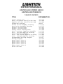
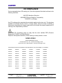
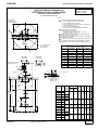
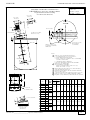
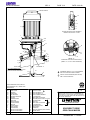
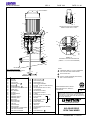
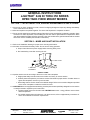
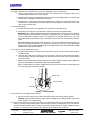
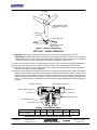
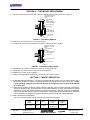
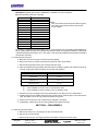
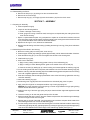
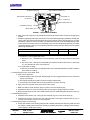
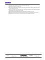
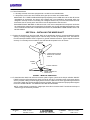
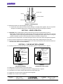
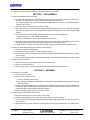
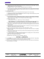
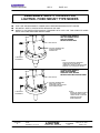
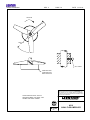
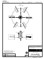
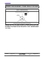
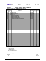
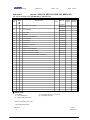
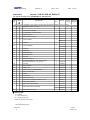
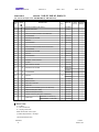
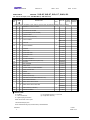
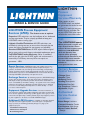
MIXER MANUAL
INSTRUCTIONS
INSTALLATION
OPERATION
MAINTENANCE
Book No. BK1978
INSTRUCTION MANUAL
LIGHTNIN SALES ORDER L880659
LIGHTNIN LINE ITEM 000010
TABLE OF CONTENTS
TITLE
DOCUMENT NO.
Safety Check List
Vert. On Center Installation Dwg.
Angular Off-Set Installation Dwg.
Dimension Drawing
Direct Drive Assembly Drawing
Gear Drive Assembly Drawing
General Instructions
General Instructions
Safety Cover Instructions
A310 (1 piece) Impeller Assembly
A310 - Bolted Impeller Drawing
A100 Impeller Assembly
R100 - One Piece Impeller Drawing
R100 - Bolted Impeller Drawing
Recommended Bolting Torques
Wiring Diagram
Spare Parts Lists 1
Spare Parts Lists 2
Spare Parts Lists 3
Spare Parts Lists 4
Spare Parts Lists 5
Sales Offices
IT-2144
IT-1985
IT-1986
DST82
L-16716
L-16717
IT-1997
IT-1994
IT-1989
L-16701
L-16673
L-17875
L-16844
L-16845
IT-850
IT-2081
IT-2044
IT-2045
IT-2046
IT-2047
IT-2048
IT-3839
SAFETY CHECK LIST
IMPORTANT WARNINGS
All LIGHTNIN Mixers and Aerators are provided with properly designed lifting devices and safety covers to avoid
potential injury and/or equipment damage. The following SAFETY CHECK LIST should be THOROUGHLY
REVIEWED AND ADHERED TO before installing, operating or performing maintenance on the mixer. FAILURE TO FOLLOW THESE INSTRUCTIONS COULD RESULT IN SERIOUS INJURY. Ensure the use of
qualified, quality trained and safety conscious personnel.
1.
Use only the lifting device, if provided, on your unit to install the mixer. Use shouldered eyebolts and tighten
securely to handle component parts. We strongly recommend that the hoist rings be of safety swivel type with
360° rotational capability. Lift per instructions in the instruction manual.
2.
DO NOT connect the motor to the power source until all components are assembled, the mixer is installed,
and all hardware is tightened to the proper torque which is specified in the operation and maintenance manuals
supplied by LIGHTNIN.
3.
DO NOT operate shaft sealing devices at temperatures or pressures higher than those specified in the manual
or on the nameplates.
4. DO NOT service the mixer until you have followed your ”Control of Hazardous Energy Sources” (lockout,
tagout procedure) as required by OSHA 29 CFR Part 1910.
5.
DO NOT touch rotating mixer parts or any part of mixer that has the potential of having a hot surface
including motor, gear drive housing, seal, shafting and flange.
6.
DO NOT operate mixer for service other than its intended use, that being fluid mixing with the mixer
attached to a rigid structure and connected to a power source appropriate to operate the drive motor.
7.
DO NOT make any field changes or modifications (horsepower, seal material components, output speed, shaft
lengths, impellers, etc.) without reviewing the changes with your LIGHTNIN Sales Representative or the
LIGHTNIN Customer Service Department.
8.
DO NOT install an aftermarket Variable Frequency Drive without first consulting your LIGHTNIN Sales
Representative or the LIGHTNIN Customer Service Department to determine the compatibility of the existing
motor with the Variable Frequency Drive.
DO NOT operate mixer until you have checked the following items:
A.
Make sure the mixer is properly grounded.
B.
Ensure all protective guards and covers are installed. Guarding of the mixer shaft below mixer mounting
surface is the responsibility of the customer.
C.
Ensure all detachable components are securely coupled to the mixer.
D.
Thoroughly REVIEW and ADHERE TO the mixer operating instructions supplied by LIGHTNIN.
E.
Ensure the mixer output shaft rotates freely by hand.
F.
Ensure all personnel and equipment are clear of rotating parts.
G.
Ensure all external connections (electrical, hydraulic, pneumatic, etc.) have been completed in accordance
with all applicable codes and regulations.
10. DO NOT enter the mixing vessel UNLESS:
A.
The mixer power supply is locked out (follow Item number 4).
B.
The mixer shaft is firmly attached to the mixer drive or the shaft is supported securely from below.
C.
You have followed applicable confined space regulations.
9.
REVISION
G
DATE 5–9–86
REVISED 05–14–07
LIGHTNIN
MIXERS AND AERATORS
®
© LIGHTNIN
2007
INST. NO. IT–2144
PAGE 1 OF 2
CE COMPLIANCE
If mixer nameplate has a CE marking on it, then the equipment furnished conforms to the
following directives:
98/37/EC Machinery Directive
89/336/EEC Electro–Magnetic Compatibility
73/23/EEC Low Voltage
Any CE marking and/or associated documentation applies to the mixer only. This has been
supplied on the basis that the mixer is a unique system. When the mixer is installed, it
becomes an integral part of a larger system which is not within the scope of supply and CE
marking is the responsibility of others.
CAUTION: CE Compliance does not imply that the mixer satisfies PED (Pressure
Equipment 97/23/EC) or ATEX (Potential
Explosive Atmospheres 94/9/EC) unless marking is clearly shown on mixer.
NOISE LEVELS
‘
SOUND PRESSURE LEVELS
Portable Series: ECL, EV – maximum 80 Dba @ 1 meter
Heavy Series: S10, 70/80, 500/600 – maximum 85 Dba @ 1 meter
THIS PRODUCT MAY BE COVERED BY ONE OR MORE OF THE FOLLOWING U. S. PATENTS:
5006283
5046245
5118199
5152934
5152606
5203630
5344235
5364184
5368390
5378062
5427450
5454986
5470152
5478149
5480228
5501523
5511881
5560709
5568975
5568985
5655780
5720286
5746536
5758965
5779359
5842377
5925293
5951162
5972661
5988604
6089748
6109449
6142458
6158722
6250797
6299776
6334705
6386753
6457853
6634784
6715913
6742923
6746147
6789314
6796707
6796770
6808306
6843612
6860474
6877750
6935771
6986507
6997444
7001063
7056095
7168641
7168848
7168849
REVISION
G
DATE 5–9–86
REVISED 05–14–07
LIGHTNIN
MIXERS AND AERATORS
®
© LIGHTNIN
2007
INST. NO. IT–2144
PAGE 2 OF 2
LIGHTNIN
MAINTENANCE AND SERVICE MANUAL
DRAWING IT–1985
CERTIFIED DIMENSION DRAWING FOR
LIGHTNIN XDQ AND XJQ SERIES MIXERS
Vertical On–Center Mounting
ISSUED – 3/15/83
REVISED – 2/26/01
ALL DIMENSIONS IN INCHES
NOTES:
TANK MAY BE
ROUND, SQUARE
OR RECTANGULAR
H
2
1
REFER TO ORDER SPECIFICATION SHEET FOR:
A. MODEL NUMBER AND MOTOR HORSEPOWER.
B. SHAFT DIAMETER AND FULL LENGTH.
C. SHAFT CONNECTION – STANDARD CHUCK OR ALTERNATE
COUPLING CONSTRUCTION.
D. QUANTITY AND SIZE OF IMPELLERS.
E. IF LOWER IMPELLER IS EQUIPPED WITH STABILIZER.
2
MIXER SUPPORT CHANNEL SIZE
(NOT FURNISHED BY ”LIGHTNIN”):
TANKS UP TO AND INCLUDING 8 FEET – 4” X 7.25#
TANKS OVER 8 FEET – 6” X 8.2#
MIXER WEIGHT CAN VARY WITH MOTOR CHARACTERISTICS,
SHAFT AND IMPELLER SELECTION.
DIMENSION ”A” IS MAXIMUM. CAN VARY SLIGHTLY DEPENDING
ON MOTOR ENCLOSURE.
CONDUIT BOX NOT INCLUDED WITH EXPLOSION PROOF MOTOR.
H
3
H
H
4
5
6
IMPELLER
EQUISPACED TANK BAFFLES NOT FURNISHED BY ”LIGHTNIN”.
SEE SPECIFICATION SHEET FOR BAFFLE DIMENSIONAL DATA.
ROTATION
(4) 11/16 MTG. HOLES
IN TOP FLANGE
OF CHANNELS
MINIMUM DIAMETER OPENING REQUIRED TO PASS
IMPELLER WHEN DETACHED FROM SHAFT
IMPELLER
DIA.
6
XDQ or XJQ
174 thru 350
XDQ or XJQ
30 thru 117
8–1/4
MAX.
7–1/2
MAX.
FOR AIR MOTOR UNITS,
REFER TO DS–T–85.
2
1–3/4
9 MAX.
MINIMUM
OPENING (IN.)
IMPELLER
DIA.
MINIMUM
OPENING (IN.)
2.5
2
10.0
7–3/4
3.4
2–5/8
11.2
8–3/4
9–1/4
3.8
3
11.8
4.5
3–1/2
12.8
10
5.2
4
13.6
10–5/8
5.9
4–5/8
15.1
11–3/4
6.3
4–7/8
15.6
12–1/4
6.8
5–1/4
17.0
13–1/4
7.6
6
19.0
15
A
5
E
A
C
SEE DETAIL ”A”
F – CPLG. BOLT DIA.
1–5/16
B
B
DETAIL ”A”
ALTERNATE COUPLING
CONSTRUCTION
(SEE NOTE 1c)
2
”K”
SQUARE
BAFFLE
WIDTH
1
APPR.
WGT.
LBS.
XDQ–30
51
XDQ–43
56
XDQ–87
60
21–3/4
TANK SIZE
BAFFLE
LENGTH
B
A
MODEL
4
WITH
CHUCK
WITH
CPLG.
C
E
F
H
K
6–1/2
3–1/8
0
3–7/8
3/8
4
10
6–3/4
3–1/8
0
4–3/4
1/2
5–1/2
13
6–3/8
2–3/4
1–3/8 3–7/8
3/8
4
10
7
2–3/8
1–5/8 4–3/4
1/2
4–1/2
11
6–3/4
3
1–7/8 4–3/4
1/2
5–1/2
13
21–1/2
1
ADJUSTABLE
XDQ–117
70
22–1/2
XDQ–174
135
24–1/4
XDQ–230
140
XDQ–350
155
XJQ–30
63
XJQ–43
66
XJQ–65
70
XJQ–87
83
XJQ–117
89
25–3/8
XJQ–174
155
28–3/4
XJQ–230
200
XJQ–350
225
26
1
23–1/4
24–5/8
30–1/2
CERTIFICATION: This drawing, when used in conjunction with the attached specification sheet for
LIGHTNIN Order _________________________ represents certified dimensions.
© LIGHTNIN
2001
LIG H TN IN
M AIN TEN AN C E AN D SER VIC E M AN U AL
D R AW IN G IT--1986
C ER TIFIED D IM EN SIO N D R AW IN G FO R
LIG H TN IN XD Q A N D XJQ SER IES M IXER S
A ngularO ff--C enterM ounting
SH EET 1 of2
ISSU ED --3/15/83
R EVISED --2/26/01
ALL D IM EN SIO N S IN IN C H ES
XD Q orXJQ
30 thru 117
XD Q orXJQ
174 thru 350
7--1/2
M AX.
8--1/4
M AX.
IM PELLER
1--3/4
R O TATIO N
2
A
9 M AX.
A
5
C
H
SH O R T O FFSET
CL TAN K
H
B
FO R AIR M O TO R U N ITS,
R EFER TO D S --T--85.
SEE D ETAIL ”A”
J
1--5/16
D
CL SH AFT
J
2
LO N G
O FFSET
TAN K SIZE
(4)11/16 M TG .H O LES
IN TO P FLAN G E
O F C H AN N ELS
R EFER TO SH EET 2 O F 2
FO R M IXER PO SITIO N IN G
D IM EN SIO N S
10 O
1
1
N O TES:
1
R EFER TO O R D ER SPEC IFIC ATIO N SH EET FO R :
A. M O D EL N U M BER AN D M O TO R H O R SEPO W ER .
B. SH AFT D IAM ETER AN D FU LL LEN G TH .
C . SH AFT C O N N EC TIO N --STAN D AR D C H U C K O R ALTER N ATE
C O U PLIN G C O N STR U C TIO N .
D . Q U AN TITY AN D SIZE O F IM PELLER S.
E. IF LO W ER IM PELLER IS EQ U IPPED W ITH STABILIZER .
2
M IXER SU PPO RT C H AN N EL SIZE
(N O T FU R N ISH ED BY ”LIG H TN IN ”):
TAN KS U P TO AN D IN C LU D IN G 8 FEET --4”X 7.25#
TAN KS O VER 8 FEET --6”X 8.2#
M IXER W EIG H T C AN VAR Y W ITH M O TO R C H AR AC TER ISTIC S,
SH AFT AN D IM PELLER SELEC TIO N .
D IM EN SIO N ”A”IS M AXIM U M .C AN VAR Y SLIG H TLY D EPEN D IN G
O N M O TO R EN C LO SU R E.
C O N D U IT BO X N O T IN C LU D ED W ITH EXPLO SIO N PR O O F M O TO R .
AD JU STABLE
1
6
3
4
5
6
R EFER TO SH EET 2 O F 2 FO R M IN IM U M D IAM ETER O PEN IN G
R EQ U IR ED TO PASS IM PELLER /S W H EN D ETAC H ED FR O M SH AFT.
J
L
M O D EL
APPR .
W G T.
LBS.
XD Q --30
51
XD Q --43
56
XD Q --87
60
J
B
A
4
W ITH
CHUCK
W ITH
C PLG .
C
6--1/2
3--1/8
0
6--3/4
3--1/8
0
6--3/8
D
E
F
H
3/8
4
J
L
M
21--1/2
H
H
(4)11/16 D IA.
M O U N TIN G H O LES
M
AN G LE R ISER
BASE D ETAIL
2--1/4 3--7/8
5--3/8 12--1/4
10
21--3/4
XD Q --117
70
22--1/2
XD Q --174
135
24--1/4
XD Q --230
140
XD Q --350
155
XJQ --30
63
XJQ --43
66
XJQ --65
70
XJQ --87
83
XJQ --117
89
25--3/8
XJQ --174
155
28--3/4
XJQ --230
200
XJQ --350
225
3
4--3/4
1/2
2--3/4
1--3/8 2--1/4 3--7/8
3/8
7
2--3/8
1--5/8 2--1/4 4--3/4
6--3/4
3
1--7/8
5--1/2 7--5/8 16--3/4 13--1/2
26
E
F --C PLG .BO LT D IA.
23--1/4
4
5--3/8 12--1/4
10
1/2
4--1/2 5--7/8 13--1/4
11
1/2
5--1/2 7--5/8 16--3/4 13--1/2
24--5/8
B
D ETA IL ”A ”
ALTER N ATE C O U PLIN G
C O N STR U C TIO N
(SEE N O TE 1c)
3
4--3/4
30--1/2
C ER TIFIC ATIO N :This draw ing,w hen used in conjunction w ith the attached specification sheetfor
LIG H TN IN O rder_________________________ represents certified dim ensions.
© LIG H TN IN
2001
LIG H TN IN
M AIN TEN AN C E AN D SER VIC E M AN U AL
D R AW IN G IT--1986
SH EET 2 of2
ISSU ED --3/15/83
R EVISED --4/2/03
XD Q & XJQ SER IES M IXER PO SITIO N IN G
D ATA
B A SED O N 7O A N G U LA R O FF--SET
M O U N TIN G
XD Q & XJQ SER IES M IXER PO SITIO N IN G
D ATA
B A SED O N 10O A N G U LA R O FF--SET
M O U N TIN G
ALL D IM EN SIO N S IN IN C H ES (m m )
TAN K
D IA.
inches
24
27
30
36
42
48
54
60
66
72
78
84
90
96
102
108
114
120
M AXIM U M
TAN K
D EPTH
m m inches
36
610
41
685
45
760
54
915
63
1065
72
1220
81
1370
1525
90
1675 100
1830 108
1980 117
2135 126
2285 135
2440 144
2590 154
2745 162
2895 171
3050 180
mm
915
1040
1145
1370
1600
1830
2055
2285
2540
2745
2970
3200
3430
3660
3910
4115
4345
4575
LO N G O FFSET
inches
6--3/4
7--5/8
8--5/16
9--7/8
11--1/2
13
14--1/2
16--1/8
17--7/8
19--1/4
20--3/4
22--3/8
24
25--1/2
27--1/4
28--5/8
30--3/16
31--3/4
mm
170
195
210
250
290
330
370
410
455
490
525
570
610
650
690
730
765
810
SH O R T
O FF-SET
inches
3--7/8
4--3/8
4--3/4
5--3/4
6--5/8
7--1/2
8--1/2
9--5/16
10--5/16
11--1/8
12
13
13--3/4
14--3/4
15--3/4
16--9/16
17--7/16
18--5/16
TAN K
D IA.
mm
100
110
120
145
170
190
215
235
260
280
305
330
350
375
400
420
445
465
inches
24
27
30
36
42
48
54
60
66
72
78
84
90
96
102
108
114
120
M AXIM U M
TAN K
D EPTH
m m inches
48
610
54
685
60
760
72
915
84
1065
96
1220
1370 108
1525 120
1675 132
1830 144
1980 156
2135 168
2285 180
2440 192
2590 204
2745 216
2895 228
3050 240
mm
1220
1370
1525
1830
2135
2440
2745
3050
3355
3660
3965
4270
4575
4880
5185
5490
5795
6100
LO N G O FFSET
inches
6--3/8
7--1/8
7--13/16
9--1/4
10--3/4
12--1/4
13--11/16
15--1/8
16--5/8
18--1/16
19--1/2
21
22--7/16
23--7/8
25--3/8
26--13/16
28--5/16
29--3/4
SH O R T
O FF-SET
mm
inches
5--1/8
165
5--3/4
180
200 6--5/16
7--1/2
235
8--3/4
275
315 9--15/16
350 11--1/8
385 12--5/16
425 13--1/2
460 14--3/4
495 15--15/16
535 17--1/8
570 18--3/8
610 19--9/16
645 20--3/4
680 21--15/16
720 23--3/16
755 24--3/8
mm
130
145
160
190
225
255
285
315
345
375
405
435
470
500
530
560
590
620
N O TE:
1
C O N SU LT FAC TO R Y FO R TAN K D IAM ETER S O R D EPTH S N O T LISTED .
M IN IM U M D IAM ETER O PEN IN G R EQ U IR ED TO PASS
IM PELLER W H EN D ETAC H ED FR O M SH AFT
IM PELLER
D IA.
M IN IM U M
O PEN IN G (IN .)
IM PELLER
D IA.
M IN IM U M
O PEN IN G (IN .)
2.5
2
10.0
7--3/4
3.4
2--5/8
11.2
8--3/4
3.8
3
11.8
9--1/4
4.5
3--1/2
12.8
10
5.2
4
13.6
10--5/8
5.9
4--5/8
15.1
11--3/4
6.3
4--7/8
15.6
12--1/4
6.8
5--1/4
17.0
13--1/4
7.6
6
19.0
15
C ER TIFIC ATIO N :This m ounting data,w hen used in conjunction w ith the dim ension draw ing and orderspecification sheetforthe
LIG H TN IN O rderN um berlisted on Sheet1 of2 represents certified dim ensions.
© LIG H TN IN
2001
SALES DATA BOOK
SEC. 2
PAGE 51.0
DATE 9–30–99
MOTOR HANDLE
38
46
59
4
41
3
MOTOR AND DRIVE SHAFT ASSEMBLY
MODELS XDQ 30 THRU 117 ONLY
1
2/20
36
46
23
4
38
38
27
34
24
67
68
48
8/43
50
21
18
42
25
DETAIL ”A”
47
ALTERNATE COUPLING CONSTRUCTION
(ITEMS 8, 11, 18, 21 & 34 NOT FURNISHED)
49
11
102/103
100 – ANGLE RISER ASS’Y
FURNISHED ONLY FOR UNITS WITH
ANGULAR OFFSET MOUNTING
SEE DETAIL ”A”
45
42
44
1
HARDWARE ITEMS 47, 48, 49 & 50 FURNISHED
ONLY FOR UNITS WITH ANGLE RISERS.
2
SAFETY COVER FURNISHED (NOT SHOWN).
SEE IT–1989 FOR DETAILS.
ISO 9001
WHEN ORDERING PARTS, SPECIFY;
MACHINE SERIAL NO., ITEM NO. AND
DRAWING NO.
41
38
36
34
27
25
24
23
21
20
18
11
8
4
3
2
1
ITEM
MOTOR
DRIVE SHAFT
HOUSING
CHUCK GRIP
BALL BEARING
FLEXIBLE MOUNTING
OIL SEAL
RETAINING RING
SNAP RING
BRASS WASHER
CHUCK WASHER
LIMIT PIN
CHUCK SCREW
SHAFT SCREW
LOCKWASHER
HEX HEAD CAP SCREW
HEX HEAD CAP SCREW
PART NAME
CERTIFIED
105
103
102
100
68
67
59
50
49
48
47
46
45
44
43
42
2
SAFETY COVER
ANGLE RISER (R.H.)
ANGLE RISER (L.H.)
ANGLE RISER ASSEMBLY
LOCKWASHER
HEX HEAD CAP SCREW
WASHER (XDQ30 THRU 117 ONLY)
PLAINWASHER
HEX NUT
1
HEX HEAD CAP SCREW
LOCKWASHER
MOTOR SHAFT KEY
SET SCREW
IMPELLER
HEX KEY WRENCH (NOT SHOWN)
MIXER SHAFT
ITEM
PART NAME
© LIGHTNIN
1999
ALL EQUIPMENT DESIGN AND APPLICATION DATA SHOWN
HEREIN AND RELATED KNOW-HOW IS CONFIDENTIAL AND
THE PROPERTY OF THE LIGHTNIN GROUP OF COMPANIES.
NO USE OR DISCLOSURE THEREOF MAY BE MADE WITHOUT
OUR WRITTEN PERMISSION.
R
MIXERS AND AERATORS
ASSEMBLY DRAWING
XDQ DIRECT DRIVE
OPEN TANK MIXERS
DRAWING NO. L–16716B
SALES DATA BOOK
SEC. 2
PAGE 69.0
DATE 5–1–00
MOTOR HANDLE
31
46
4
59
41
3
MOTOR SHAFT AND PINION ASSEMBLY
MODELS XJQ 30 THRU 117 ONLY
46
1
2/20
71
60
32
4
31
37
39
70
22
27
24
36
61
23
29
26
28
38
23
23
29
28
21
26
38
18
8/43
67
68
69
34
48
11
42
50
DETAIL ”A”
ALTERNATE COUPLING CONSTRUCTION
(ITEMS 8, 11, 18, 21 & 34 NOT FURNISHED)
25
47
49
102/103
100 – ANGLE RISER ASS’Y
FURNISHED ONLY FOR UNITS WITH
ANGULAR OFFET MOUNTING
NOTES:
45
42
38
37
36
34
32
31
30
29
28
27
26
25
24
23
22
21
20
18
11
8
4
3
2
1
DRIVE SHAFT
SPACER
HOUSING
CHUCK GRIP
INTERNAL GEAR 2
PINION 2
GEAR/PINION SET 2
OUTER RING AND ROLLER ASSY
INNER RING
BALL BEARING
OIL SEAL
FLEXIBLE MOUNT
OIL SEAL
RETAINING RING (2)
RETAINING RING
SNAP RING
BRASS WASHER
CHUCK WASHER
LIMIT PIN
CHUCK SCREW
PINION SCREW
LOCKWASHER – PINION SCREW
HEX HEAD CAP SCREW
HEX HEAD CAP SCREW
105
103
102
100
71
70
69
68
67
61
60
59
50
49
48
47
46
45
44
43
42
41
39
ITEM
PART NAME
ITEM
1
HARDWARE ITEMS 47, 48, 49 & 50 FURNISHED
ONLY FOR UNITS WITH ANGLE RISERS.
2
SOLD IN SETS ONLY.
3
SAFETY COVER FURNISHED (NOT SHOWN).
SEE IT–1989 FOR DETAILS.
44
SAFETY COVER 3
ANGLE RISER (R.H.)
ANGLE RISER (L.H.)
ANGLE RISER ASSEMBLY
SLINGER
(XJQ 174 THRU 350 ONLY)
OIL SEAL
HEX NUT (XJQ 30 THRU 117 ONLY)
LOCKWASHER
HEX HEAD CAP SCREW
GRIP SPRING LOCKNUT
O–RING
WASHER (XJQ 30 THRU 117 ONLY)
PLAIN WASHER
HEX NUT
1
HEX HEAD CAP SCREW
LOCKWASHER
MOTOR SHAFT KEY
SET SCREW
IMPELLER
HEX KEY WRENCH (NOT SHOWN)
MIXER SHAFT
MOTOR
2
GRIP SPRING SET
ISO 9001
WHEN ORDERING PARTS, SPECIFY
MACHINE SERIAL NO., ITEM NO. &
DRAWING NO.
CERTIFIED
© LIGHTNIN
2000
ALL EQUIPMENT DESIGN AND APPLICATION DATA SHOWN
HEREIN AND RELATED KNOW-HOW IS CONFIDENTIAL AND
THE PROPERTY OF THE LIGHTNIN GROUP OF COMPANIES.
NO USE OR DISCLOSURE THEREOF MAY BE MADE WITHOUT
OUR WRITTEN PERMISSION.
R
MIXERS AND AERATORS
ASSEMBLY DRAWING
XJQ GEAR DRIVE
OPEN TANK MIXER
PART NAME
DRAWING NO. L–16717D
GENERAL INSTRUCTIONS
LIGHTNIN XJQ 30 THRU 350 SERIES
OPEN TANK FIXED MOUNT MIXERS
SECTION 1 – INITIAL INSPECTION, SHIPPING ARRANGEMENTS AND STORAGE
1.1 As soon as you have uncrated your mixer, check it for shipping damage and report any damage immediately
to the carrier and to our factory.
1.2 Mixer and impellers are packed together. The mixer shaft is packed in a separate container.
1.3 Do not remove wrappings or protective coatings if the mixer is to be stored before it is placed in operation. Store
the mixer in a clean, dry location, with circulating air, free from wide or rapid variations in temperature. When
gear drive models have been stored for more than a year, the condition of the gear lubricant should be checked
before the mixer is installed (see lubrication instructions).
SECTION 2 – MIXER AND SHAFT INSTALLATION
2.1 Refer to the installation drawing for proper mixer mounting and location.
2.2 All mixers are furnished with safety covers. Do not remove during operation.
a . Stop unit and disconnect power supply before removing safety cover.
b . Re–install safety cover after servicing the unit.
4 VENT HOLES
4 HEX HEAD
FASTENERS
SAFETY COVER
2.3 Impeller rotation must be according to the arrow on the mixer nameplate.
a . Single phase totally enclosed motors are wired at our factory for correct rotation.
b . All three phase and explosion proof motors must be field wired for proper rotation. If rotation does not
agree with nameplate, reverse any two line leads.
c . Dual voltage motors must be wired for the desired voltage. Refer to the connection diagrams provided
on the motor nameplate or inside the conduit box cover.
2.4 LIGHTNIN Mixers are equipped with ball bearing chemical plant motors specifically designed for mixer service
in totally enclosed or explosion proof construction.
a . Constant speed mixers are furnished with LIGHTNIN DURA–MIX energy efficient motors unless
otherwise specified.
b . For variable speed mixers with electronic or air driven motors, refer to supplementary instructions for
motor control data and connection requirements.
REVISION
C
DATE 3–16–83
LIGHTNIN
REVISED 2–26–01
MIXERS AND AERATORS
®
© LIGHTNIN
2001
INST. NO. IT–1997
PAGE 1 OF 9
2.5 Single Phase Motors for XDC30 thru 87 (or motors nameplated 1/4 thru 1 horsepower):
a . Totally enclosed motors are furnished with eight foot cords fitted with UL approved three prong
grounded plugs suitable for the correct voltage.
b . Explosion proof motors are furnished with a pipe tap connection and suitable leads. A conduit box with
internal switch is available for explosion proof service.
c . All DURA–MIX single phase motors are equipped with an internal over–temperature device with
manual reset. If the thermal trips, wait fifteen (15) minutes and depress the reset button on the motor
body. A click indicates reset.
2.6 Three Phase Motors:
a . All totally enclosed motors are equipped with a conduit box and suitable leads.
b . All explosion proof motors are furnished with a pipe tap connection and suitable leads.
IMPORTANT: ALL THREE PHASE MOTORS (except explosion proof on XDC 30 thru 65 or other XP
motors nameplated 3/4 horsepower and below) are equipped with over–temperature thermostats
which are designed to interrupt current in the holding coil of magnetic starters only. The motor
thermostats will reset themselves, but the control panel ”start” button must be depressed to start the
motor.
EXPLOSION PROOF MOTORS on XDC 30 thru 65 or XP motors nameplated 3/4 horsepower and
below are equipped with automatic over–temperature circuits which can trip and reset themselves
after the motor cools. TO AVOID INJURY DUE TO UNEXPECTED START UP, DISCONNECT FROM
POWER UNTIL THE MOTOR COOLS.
2.7 Procedure for units equipped with chuck:
a . To install the mixer shaft, back off the chuck screw (refer to Figure 1) as far as the limit pin will allow.
DO NOT FORCE.
b . Insert the mixer shaft into the chuck bore as far as it will go, and draw up the chuck screw with the
wrench provided, rotating the shaft slightly back and forth to make sure the chuck grip seats against
the flat of the shaft.
c . Tighten the chuck screw with the wrench provided. The wrench has been properly sized to tighten the
screw. DO NOT IMPACT THE WRENCH OR USE AN EXTENSION.
NOTE: A safety feature is provided by a slight taper in the flat on the mixer shaft. The shaft cannot drop
out unless the grip is intentionally released.
CHUCK GRIP
CHUCK
CHUCK SCREW
LIMIT PIN
FIGURE 1 – CHUCK DETAILS
2.8 Procedure for units equipped with couplings:
a . Connect the mixer shaft (42) to the drive shaft (38) by bolting the coupling halves together.
CAUTION: Care should be exercised in order to prevent damage to the coupling rabbets, and to insure
proper seating of the coupling halves.
2.9 Position the impeller(s) on the mixer shaft. Refer to the specification sheet for recommended dual impeller
spacing. The larger wedge shaped portion of the hub body must face up towards the mixer. The bottom of
the hub is stamped ”DOWN”. Refer to Figure 2 for general orientation reference. Tighten impeller set screws
securely. For unusually severe conditions, the shaft should be spotted for the set screws.
REVISION
C
DATE 3–16–83
LIGHTNIN
REVISED 2–26–01
MIXERS AND AERATORS
®
© LIGHTNIN
2001
INST. NO. IT–1997
PAGE 2 OF 9
ROTATION
LARGE WEDGE SHAPED
PORTION OF HUB MUST
FACE UP.
LEADING
EDGE
CONVEX SURFACE
”DOWN” STAMPED ON
LOWER FACE
FIGURE 2 – IMPELLER ORIENTATION
SECTION 3 – MIXER OPERATION
3.1 LIGHTNIN mixers are designed to operate continuously at normal or low liquid levels, and in air.
IMPORTANT: Variable speed drives sometimes have critical ranges where the unit should not be operated
during drawoff or in air. These ranges will be indicated on a warning decal at the speed control. It is not good
practice to operate any mixer continuously when extreme vortexing or surging occurs.
3.2 At the end of two weeks service, check the housing cap screws, chuck screw and mounting bolts for tightness.
3.3 Dirt on the motor case acts as an insulator to prevent proper cooling. Always keep the motor clean.
3.4 At the end of the mixing cycle, it is good practice to turn off the mixer before the tank has been drained to a
level which will result in excessive splashing.
3.5 A built–in shock load feature is included in the gear drive. The grip springs (39) provide a keyless friction drive
between the gear and the drive shaft, and the springs will slip before the mixer is damaged. Therefore, if the
mixer shaft does not rotate when the motor is turned on, remove the motor (41) from the housing (36) and
tighten the grip spring locknut (61) securely. The table below lists the recommended tightening torque for this
locknut. If a torque wrench is not available, be sure the locknut is tightened sufficiently to prevent grip spring
slippage.
INTERNAL GEAR (30)
GRIP SPRING LOCKNUT (61)
GRIP SPRING SPACER (37)
SLINGER (71)
OIL SEAL (70)
PINION (31)
GRIP SPRING SET (39)
RETAINING RING (22)
DRIVE SHAFT (38)
FIGURE 3 – GRIP SPRING ASSEMBLY
MODEL
XJQ 30
XJQ 43
XJQ 65
XJQ 87 & 117
20
20
50
50
TIGHTENING TORQUE
IN FOOT–POUNDS
XJQ 174 XJQ 230 & 350
125
125
RECOMMENDED TIGHTENING TORQUE FOR GRIP SPRING LOCKNUT
REVISION
C
DATE 3–16–83
LIGHTNIN
REVISED 2–26–01
MIXERS AND AERATORS
®
© LIGHTNIN
2001
INST. NO. IT–1997
PAGE 3 OF 9
SECTION 4 – FLEX MOUNT REPLACEMENT
4.1 The flex mounts can be removed with a long bolt and two pieces of tubing as shown in Figure 4.
HEX HEAD CAP SCREW
(MINIMUM 5 INCHES
LONG)
PLAIN WASHER
TUBING
(7/8 INCH MAXIMUM
OUTSIDE DIAMETER)
FLEX MOUNT (25)
HOUSING (36)
TUBING
(2 INCH MINIMUM
INSIDE DIAMETER)
PLAIN WASHER
OR PLATE
HEX NUT
FIGURE 4 – FLEX MOUNT REMOVAL
4.2 Tighten the nut until the mount is free of the housing.
4.3 To install new mounts, use a long bolt and a piece of tubing as shown in Figure 5.
HEX HEAD CAP SCREW
(MINIMUM 4–1/2 INCHES
LONG)
PLAIN WASHER
TUBING
(1–3/8 INCH MINIMUM
INSIDE DIAMETER)
HOUSING (36)
FLEX MOUNT (25)
PLAIN WASHER
HEX NUT
FIGURE 5 – FLEX MOUNT INSTALLATION
4.4
4.5
4.6
4.7
Lubricate the mount with a natural rubber lubricant or liquid hand soap.
Tighten the nut until the mount is tight with the housing base.
Replace ALL mounts if one is replaced.
Tighten mounting hardware to 85 ft–lbs. Use double nuts to lock in position.
SECTION 5 – MIXER LUBRICATION
5.1 STANDARD GEAR LUBRICANT – The factory supplied NLGI EP0 grease is a high quality lubricant with a
lithium base, suitable for operation in ambient temperatures ranging between +50° F and +200° F. Under
normal operating conditions, this lubricant need not be changed until the unit has been dismantled
for some reason.
5.2 Under adverse operating conditions, periodic changes of lubricant may be necessary. Adverse conditions are
defined as operating in very humid, dust laden or chemical atmospheres, or where wide variations in ambient
temperature occurs. Such adverse conditions can lead to deterioration of lubricant compounds and additives,
and it is recommended that the condition of the grease be checked within six months after start up. Reputable
lubricant suppliers can analyze the grease and recommend economical, safe change schedules.
5.3 Gear Lubricant Recommendations:
Use only a lubricant suitable for the temperature and operating conditions.
REVISION
C
AMBIENT
TEMP.
RANGE
NLGI #
BASE
50° F to 200° F
EP 0
LITHIUM
MIN. OIL
VISCOSITY
SUS
750 @ 100° F
76 @ 210° F
DATE 3–16–83
LIGHTNIN
REVISED 2–26–01
MIXERS AND AERATORS
®
MAX.
OPERATING
TEMP.
200° F
© LIGHTNIN
2001
INST. NO. IT–1997
PAGE 4 OF 9
LIGHTNIN EP0 grease (part number 123620PSP) is available in 2 pound containers.
Approved Alternate Lithium EP 0 Greases
MANUFACTURER
PRODUCT
Agip
GR MU/EP 0
Amoco
Amolith EP 0
BP
A0, CA or CS0
Castrol
Helveum 0, Impervia CL
Chevron
Duralith EP 0
Citgo
Premium Lithium EP0
Elf
EPEXA0
Exxon
Lidok EP0
Lubriplate
630 AAA
Mobil
Mobilux EP 0
Pennzoil
Pennlith EP710
Shell
Alvania EP 0
Sunoco
Prestige 740 EP
Texaco
Multifak EP 0
NOTE:
This cross reference list should be used as a guide
only. Before using these products, discuss with
a local supplier.
For operation in ambient temperatures below +50° F, we recommend use of a synthetic grease (Mobil SHC
007 or equal) compounded only with synthesized hydrocarbon fluids. This grease is suitable for a wide range
of ambient temperatures between –30° F and +200° F, and should be considered where seasonal lubricant
changes are necessary
5.4 Changing Gear Lubricant:
a . Make sure the mixer housing is vertical to prevent spillage.
b . Remove the motor to housing cap screws and lift off the motor by its handle.
c . Remove all old grease from the gear chamber and wipe clean.
d . Pack the chamber with fresh grease (see table below). Paddle the grease to fill voids and remove air
pockets, rotating the shaft and shaking the housing while paddling.
GEAR CHAMBER CAPACITY
GREASE – LBS.
MODEL
XJQ 30 & 43
XJQ 65 thru 117
XJQ 174 thru 350
2.25 3.0 1.25
PACK CHAMBER FLUSH WITH TOP OF THE INTERNAL GEAR.
PACK CHAMBER TO WITHIN 3/4” BELOW TOP OF INTERNAL GEAR.
e . Check the O–ring in the flange of the motor and replace if it is deformed, cut or deteriorated.
f . Carefully align the motor rabbet and guide into the housing bore. Guide the pinion into mesh with the
gear, and make sure the O–ring is properly seated in the groove.
g . Check for free movement of all components by rotating the drive shaft.
h . If satisfactory, replace the motor to housing hardware and tighten securely.
SECTION 6 – DISASSEMBLY
6.1 Removing the Mixer Shaft:
a . Remove the limit pin (11) by driving it into the counterbored hole.
b . Remove the chuck screw (8).
c . Remove snap ring (21), chuck grip (34) and chuck washer (18) from the chuck screw.
REVISION
C
DATE 3–16–83
LIGHTNIN
REVISED 2–26–01
MIXERS AND AERATORS
®
© LIGHTNIN
2001
INST. NO. IT–1997
PAGE 5 OF 9
6.2 Removing the Motor from the Housing:
a . Set the mixer in a vertical position to prevent spilling the gear lubricant.
b . Remove the four housing cap screws and washers (1, 2 & 20).
c . Raise the motor (41) by its handle (35) or eyebolts to separate the motor from the housing (36).
d . Remove the O–ring (60).
6.3 Removing the Pinion from the Motor:
a . Hold the pinion (31) from turning and remove the pinion cap screw (4) in one of the following ways:
1 .XJQ 30 thru 117 – Use a Phillips screwdriver.
2 .XJQ 174 thru 350 – Use a 5/16 inch hex key wrench.
3 .XJQ 174 thru 350 (with a nylon slinger) – The slinger (71) must be removed by breaking it. Place
a wooden block under the slinger and strike the opposite side with a chisel.
b . Remove the pinion with a bearing puller.
6.4 Removing Drive Shaft, Bearings and Oil Seals from the Housing:
a . Remove the lubricant from the gear chamber.
b . Remove the grip spring locknut (61) from the upper end of the drive shaft (38). Use one of the following
methods to hold the drive shaft from turning:
1 . Procedure for units equipped with chuck:
a .XJQ 30 thru 117 – Insert a hex key wrench (43) in the chuck screw.
b .XJQ 174 thru 350 – Remove the chuck assembly per paragraph 6.5. Insert a 1 foot length of 1
inch diameter bar into the chuck grip bore.
2 . For models with rigid couplings:
a .Bolts can be inserted into the coupling half and a bar interlocked between the bolts to keep the
drive shaft from rotating.
c . Thread a nut on the end of the drive shaft (38) to protect the threads when pressing out the shaft.
d . Mount the housing in an arbor press, motor end upward, and press the drive shaft clear of the internal
gear bore.
e . Remove the internal gear (30), the two grip spring sets (39) and the grip spring spacer (37).
f . Remove the drive shaft, with the bearing inner ring (29) in place, through the lower opening in the
housing.
g . If it is necessary to remove the bearing inner ring, start it from its seat with a thin screwdriver or wedge,
then remove it from the drive shaft with a bearing puller.
h . XJQ 174 thru 350 ONLY – Pry the oil seal (70) from the housing bore as shown in Figure 6.
1 .Insert a 7/8 bolt into the ball bearing (27) bore.
2 .Use the bolt head as a fulcrum and pry out the oil seal (70) with pliers.
PLIERS
70
22
27
24
7/8 BOLT
FIGURE 6 – OIL SEAL REMOVAL
i . Use Wades Truarc No. 4 pliers to remove the internal retaining ring (22).
j . Remove the ball bearing (27) and upper oil seal (24) through the upper opening of the housing.
k . Remove the internal retaining rings (23).
l . Mount the housing, motor end upward, in an arbor press and press out the oil seal (26) and the outer
ring and roller assembly (29).
REVISION
C
DATE 3–16–83
LIGHTNIN
REVISED 2–26–01
MIXERS AND AERATORS
®
© LIGHTNIN
2001
INST. NO. IT–1997
PAGE 6 OF 9
6.5 Disassembling the Chuck:
a . Remove the limit pin (11) by driving it into the counterbored hole.
b . Remove the chuck screw (8).
c . Remove snap ring (21), chuck grip (34) and chuck washer (18) from the chuck screw.
SECTION 7 – ASSEMBLY
7.1 Preparing for Assembly:
a . Clean all parts thoroughly.
b . Inspect for the following defects:
1 .Cracks or damage of the housing.
2 .Dents, gouges or scoring of the drive shaft, housing bore, and particularly the mating faces of the
motor and the housing.
c . Repair or replace defective parts. It is good practice to replace an oil seal which has been removed
from the housing. Apply a small quantity of bearing grease to the housing bore and around the oil seal
lip to provide lubrication and to make the seal more effective.
d . Replace the O–ring if it is cut, deformed or deteriorated.
e . Replace the ball bearing and roller bearing (including the bearing inner ring) if they show indications
of wear.
7.2 Assembling the Drive Shaft in the Housing:
a . Mount the housing (36) in an arbor press, motor end up.
b . Press the upper oil seal (24), sealing lip upward, approximately 1/8 inch below the shoulder of the bore.
c . Press the ball bearing (27) on its outer race against the shoulder of the housing bore.
d . Install retaining ring (22).
e . XJQ 174 thru 350 ONLY:
1 .Apply a heavy coating of ball bearing grease to the top of the ball bearing (27).
2 .Apply a coating of Loctite ”Bearing Mount” grade to the outside of the new oil seal (70).
3 .Press the oil seal (70), sealing lip up, into the housing until it seats against the retaining ring (22).
f . Turn the housing motor end down in the press, and install the inner of the two lower retaining rings (23).
g . Pack the outer ring and roller assembly (29) with a suitable bearing grease and press it into the housing
bore until it registers against the retaining ring.
h . Press the oil seal (26), with its sealing lip towards the motor end of the housing, against the outer ring
and roller assembly.
i . Install outer retaining ring (23).
j . If the bearing inner ring (28) has been removed from the drive shaft (38), press it in place.
k . Apply a thin film of light oil on the tapered surfaces only of each grip spring set.
CAUTION: For proper operation of the grip springs, oil must not get between the grip spring driving
surfaces and the drive shaft or gear bore.
l . Install the inner ring of the lower grip spring set (39) so that the thicker edge seats against the shaft
shoulder.
m . Place the housing on its side and grease the lips of the oil seals.
n . Hold the internal gear (30) in place in the gear chamber and pass the drive shaft through its bearings
as far as it will go into the hub of the gear.
o . With the gear on the end of the shaft, turn the housing motor end down and press the shoulder of the
drive shaft against the inner race of the ball bearing (27).
p . Turn the housing motor end up. Center the internal gear in the drive shaft and install the external ring
of the lower grip spring set (39), grip spring spacer (37) and upper grip spring set (39). Both grip spring
sets should be installed with the thicker edge of the external ring upward (see Figure 7).
REVISION
C
DATE 3–16–83
LIGHTNIN
REVISED 2–26–01
MIXERS AND AERATORS
®
© LIGHTNIN
2001
INST. NO. IT–1997
PAGE 7 OF 9
INTERNAL GEAR (30)
GRIP SPRING LOCKNUT (61)
GRIP SPRING SPACER (37)
SLINGER (71)
OIL SEAL (70)
PINION (31)
GRIP SPRING SET (39)
RETAINING RING (22)
DRIVE SHAFT (38)
FIGURE 7 – GRIP SPRING ASSEMBLY
q . Apply a thin coat of light oil on the threads of the drive shaft and the bottom surface of the grip spring
locknut.
r . Thread the grip spring locknut (61) onto the end of the drive shaft (finger tight). Rotate the internal gear
(30) by hand, and at the same time tighten down on the locknut until the internal gear can no longer
be rotated. Tighten the locknut securely. (The table below lists the recommended tightening torque
for this locknut. If a torque wrench is not available, be sure locknut is tightened sufficiently to prevent
grip spring slippage.) Use one of the following methods to prevent the drive shaft from turning while
performing this operation.
XJQ SERIES MODEL
TIGHTENING TORQUE (FT.–LBS)
30 & 43
65 thru 117
174 thru 350
20
50
125
RECOMMENDED TIGHTENING TORQUE FOR GRIP SPRING LOCKNUT
1 .Procedure for units equipped with chuck:
a .XJQ 30 thru 117 – Reassemble the chuck assembly. Insert a hex key wrench into the chuck
screw.
b .XJQ 174 thru 350 – With the chuck assembly removed from the drive shaft, insert a 1 foot length
of 1 inch diameter bar in the chuck grip bore.
2 .For models with coupling:
a .Bolts can be inserted into the coupling half and a bar interlocked between the bolts to keep the
drive shaft from rotating.
7.3 Assembling the Pinion on the Motor Shaft:
a . XJQ 174 thru 350 ONLY:
1 .Install the slinger on the motor shaft, allowing a gap of 1/32 inch gap between the motor oil seal and
the top of the slinger.
2 .Check shaft end play and rotate to make sure slinger rotates freely.
3 .Coat the set screw threads with Loctite and tighten the set screw securely.
b . Apply a thin film of grease to the motor shaft or pinion shaft.
c . Make sure that the motor shaft key (46) is in place in the motor shaft keyway.
d . Assemble the pinion on the motor shaft by driving it into place with light strokes of a mallet.
e . Make sure that the pinion and motor shafts butt securely, then install and tighten the pinion screw (4).
7.4 Assembling the Chuck:
a . Assemble chuck washer (18), chuck grip (34) and snap ring (21) on the chuck screw (8).
b . Thread the chuck screw into the chuck end of the drive shaft, far enough to insert the limit pin (11), so
that the end of the pin is 3/16 of an inch underflush.
7.5 Assembling the Motor to the Housing:
a . Fill the gear chamber of the housing (36) level with a suitable lubricant (see Section 5). Make sure that
the grease is solidly packed without air pockets by paddling the grease, rotating the drive shaft by
hand, tapping or shaking the housing.
REVISION
C
DATE 3–16–83
LIGHTNIN
REVISED 2–26–01
MIXERS AND AERATORS
®
© LIGHTNIN
2001
INST. NO. IT–1997
PAGE 8 OF 9
b . Clean the mating surfaces of the motor (41) and the housing (36).
c . Place the O–ring (60) on the motor (41).
d . Align the motor rabbet with the opening of the housing, and lower the motor into place using care so
as not to damage the O–ring.
e . Align the motor and housing so that the switch, conduit box or junction box of the motor are opposite
the large opening on the front of the housing.
f . Align the screw holes and install the housing cap screws and washers (1, 2 & 20).
g . Rotate the drive shaft several revolutions by hand to make sure that all parts are running freely.
h . Reassemble the mixer shaft to the unit as described in the installation instructions.
REVISION
C
DATE 3–16–83
LIGHTNIN
REVISED 2–26–01
MIXERS AND AERATORS
®
© LIGHTNIN
2001
INST. NO. IT–1997
PAGE 9 OF 9
GENERAL INSTRUCTIONS FOR
LIGHTNIN XDQ 30 THRU 350 SERIES
OPEN TANK FIXED MOUNT MIXERS
SECTION 1 – INITIAL INSPECTION, SHIPPING ARRANGEMENTS AND STORAGE
1.1 As soon as you have uncrated your mixer, check it for shipping damage and report any damage immediately
to the carrier and to our factory.
1.2 Mixer and impellers are packed together. The mixer shaft is packed in a separate container.
1.3 Do not remove wrappings or protective coatings if the mixer is to be stored before it is placed in operation. Store
the mixer in a clean, dry location, with circulating air, free from wide or rapid variations in temperature.
SECTION 2 – MOUNTING
2.1 Support the mixer by the motor handle or eye bolts and mount it on the support base. Refer to the installation
or dimension drawing.
2.2 All mixers are furnished with safety covers. Do not remove during operation. Stop unit and disconnect power
supply before removing safety cover. Reinstall safety cover after servicing the unit.
4 VENT HOLES
4 HEX HEAD
FASTENERS
FIGURE 1 – SAFETY COVER
2.3 Impeller rotation must be according to the arrow on the mixer nameplate.
a . Single phase totally enclosed motors are wired at our factory for correct rotation.
b . All three phase and explosion proof motors must be field wired for proper rotation. If rotation does not agree
with nameplate, reverse any two line leads.
c . Dual voltage motors must be wired for the desired voltage. Refer to the connection diagrams provided on
the motor nameplate or inside the conduit box cover.
SECTION 3 – MOTOR CONNECTIONS
3.1
LIGHTNIN
Mixers are equipped with ball bearing chemical plant motors specifically designed for mixer
service in totally enclosed or explosion proof construction.
a . Constant speed mixers are furnished with LIGHTNIN DURA–MIX energy efficient motors unless
otherwise specified.
b . For variable speed mixers with electronic or air driven motors, refer to supplementary instructions for motor
control data and connection requirements.
3.2 Single Phase Motors for XDQ/XJQ 30 thru 87 (or motors nameplated 1/4 thru 1 horsepower):
a . Totally enclosed motors are furnished with eight foot cords fitted with UL approved three prong grounded
plugs suitable for the correct voltage.
b . Explosion proof motors are furnished with a pipe tap connection and suitable leads. A conduit box with
internal switch is available for explosion proof service.
c . All DURA–MIX single phase motors are equipped with an internal over–temperature device with manual
reset. If the thermal trips, wait fifteen (15) minutes and depress the reset button on the motor body. A click
indicates reset.
REVISION
C
DATE 3–16–83
REVISED 2–26–01
LIGHTNIN
MIXERS AND AERATORS
®
© LIGHTNIN
2001
INST. NO. IT–1994
PAGE 1 OF 5
3.3 Three Phase Motors:
a . All totally enclosed motors are equipped with a conduit box and suitable leads.
b . All explosion proof motors are furnished with a pipe tap connection and suitable leads.
IMPORTANT: ALL THREE PHASE MOTORS (except explosion proof on XDQ 30 thru 65 or other XP motors
nameplated 3/4 horsepower and below) are equipped with over–temperature thermostats which are
designed to interrupt current in the holding coil of magnetic starters only. The motor thermostats will reset
themselves, but the control panel ”start” button must be depressed to start the motor.
EXPLOSION PROOF MOTORS on XDQ 30 thru 65 or XP motors nameplated 3/4 horsepower and below
are equipped with automatic over–temperature circuits which can trip and reset themselves after the motor
cools. TO AVOID INJURY DUE TO UNEXPECTED START UP, DISCONNECT FROM POWER UNTIL THE
MOTOR COOLS.
SECTION 4 – INSTALLING THE MIXER SHAFT
4.1 Position the impeller(s) on the mixer shaft. Refer to the specification sheet for recommended dual impeller
spacing. The larger wedge shaped portion of the hub body must face up towards the mixer. The bottom of
the hub is stamped ”DOWN”. Refer to Figure 2 for general orientation reference. Tighten impeller set screws
securely. For unusually severe conditions, the shaft should be spotted for the set screws.
ROTATION
LARGE WEDGE SHAPED
PORTION OF HUB MUST
FACE UP.
LEADING
EDGE
CONVEX SURFACE
”DOWN” STAMPED ON
LOWER FACE
FIGURE 2 – IMPELLER ORIENTATION
4.2 To install the mixer shaft, back off the chuck screw (refer to Figure 3) as far as the limit pin will allow. DO NOT
FORCE. Insert the mixer shaft into the chuck bore as far as it will go, and draw up the chuck screw with the
wrench provided, rotating the shaft slightly back and forth to make sure the chuck grip seats against the flat
of the shaft. Tighten the chuck screw with the wrench provided. The wrench has been properly sized to tighten
the screw. DO NOT IMPACT THE WRENCH OR USE AN EXTENSION.
NOTE: A safety feature is provided by a slight taper in the flat on the mixer shaft. The shaft cannot drop out
unless the grip is intentionally released.
REVISION
C
DATE 3–16–83
REVISED 2–26–01
LIGHTNIN
MIXERS AND AERATORS
®
© LIGHTNIN
2001
INST. NO. IT–1994
PAGE 2 OF 5
CHUCK GRIP
CHUCK
CHUCK SCREW
LIMIT PIN
FIGURE 3 – CHUCK DETAILS
4.3 Alternate procedure for units equipped with couplings:
a . Connect the mixer shaft to the drive shaft by bolting the coupling halves together. Use care to prevent
damage to the rabbets. Make sure the mating faces are flush before torqueing the hardware.
SECTION 5 – MIXER OPERATION
5.1 LIGHTNIN mixers are designed to operate continuously at normal or low liquid levels, and in air.
IMPORTANT: Variable speed drives sometimes have critical ranges where the unit should not be operated
during drawoff or in air. These ranges will be indicated on a warning decal at the speed control. It is not good
practice to operate any mixer continuously when extreme vortexing or surging occurs.
5.2 At the end of two weeks service, check the housing cap screws, chuck screw and mounting bolts for tightness.
5.3 Dirt on the motor case acts as an insulator to prevent proper cooling. Always keep the motor clean.
5.4 At the end of the mixing cycle, it is good practice to turn off the mixer before the tank has been drained to a
level which will result in excessive splashing.
SECTION 6 – FLEX MOUNT REPLACEMENT
6.1 The flex mounts can be removed with a long bolt and two pieces of tubing as shown in Figure 4.
HEX HEAD CAP SCREW
(MINIMUM 5 INCHES
LONG)
HEX HEAD CAP SCREW
(MINIMUM 4–1/2 INCHES
LONG)
PLAIN WASHER
PLAIN WASHER
TUBING
(7/8 INCH MAXIMUM
OUTSIDE DIAMETER)
TUBING
(1–3/8 INCH MINIMUM
INSIDE DIAMETER)
FLEX MOUNT (25)
HOUSING (36)
HOUSING (36)
TUBING
(2 INCH MINIMUM
INSIDE DIAMETER)
FLEX MOUNT (25)
PLAIN WASHER
PLAIN WASHER
OR PLATE
HEX NUT
HEX NUT
FIGURE 4
FLEX MOUNT REMOVAL
FIGURE 5
FLEX MOUNT INSTALLATION
6.2 Tighten the nut until the mount is free of the housing.
6.3 To install new mounts, use a long bolt and a piece of tubing as shown in Figure 5.
6.4 Lubricate the mount with a natural rubber lubricant or liquid hand soap.
6.5 Tighten the nut until the mount is tight with the housing base.
6.6 Replace ALL mounts if one is replaced.
REVISION
C
DATE 3–16–83
REVISED 2–26–01
LIGHTNIN
MIXERS AND AERATORS
®
© LIGHTNIN
2001
INST. NO. IT–1994
PAGE 3 OF 5
6.7 Tighten mounting hardware to 85 ft–lbs. Use double nuts to lock in position.
SECTION 7 – DISASSEMBLY
7.1 Removing the Motor from the Housing:
a . To remove the mixer shaft from the drive shaft (38), back off the chuck screw (8) as far as the limit pin (11)
will allow. The mixer shaft is now free from the chuck and can be withdrawn.
For models equipped with coupling: Remove the coupling bolts and lower the mixer shaft through the
opening in the housing.
b . Remove housing cap screws and washers (1, 2 & 20).
c . Insert a hex wrench in the chuck screw (8) to prevent the drive shaft from turning. For models with couplings,
bolts can be inserted into the coupling half and a bar interlocked between the bolts to keep the shaft from
rotating.
d . Remove the shaft screw (4) through the drive shaft bore in one of the following ways:
1 . XDQ 30 through 117 – use a Phillips screwdriver.
2 . XDQ 174 through 350 – use a 3/8 inch long shank hex wrench.
e . The upper end of the drive shaft is closely fitted to the motor shaft. Therefore, to separate the motor (41)
and housing (36), tap evenly around the upper edge of the housing with a mallet.
f . On XDQ 30 thru 117 models, the motor shaft key (46) is lightly cemented in the motor shaft keyway.
7.2 Removing Drive Shaft, Bearing and Oil Seal from the Housing:
a . Follow the procedure outlined above.
b . Use Waldes Truarc No. 4 pliers to remove retaining ring (22).
c . Mount housing, motor end upward, in an arbor press and press drive shaft (38) through the lower opening
of the housing.
d . Turn the housing motor end down, and press ball bearing (27) and oil seal (24) downward out of the housing.
7.3 Disassembling the Chuck:
a . Remove the limit pin (11) by driving it into the counterbored hole.
b . Remove the chuck screw (8).
c . Remove snap ring (21), chuck grip (34) and chuck washer (18) from the chuck screw.
SECTION 8 – ASSEMBLY
8.1 Preparing for Assembly:
a . Clean all parts thoroughly.
b . Inspect for the following defects:
1 . Cracks or damage of the housing.
2 . Dents, gouges or scoring of the drive shaft, housing bore, and particularly the mating faces of the motor
and the housing.
c . Repair or replace defective parts. It is good practice to replace an oil seal which has been removed from
the housing. Apply a small quantity of bearing grease to the housing bore and around the oil seal lip to
provide lubrication and to make the seal more effective.
d . Replace the ball bearing if it shows indications of wear.
8.2 Assembling the Drive Shaft in the Housing:
a . Mount the housing (36) in an arbor press, motor end up.
b . Press the ball bearing (27) on its outer race to the shoulder of the housing bore.
c . Turn the housing motor end down and press the oil seal (24), sealing lip inward, flush with the lower end
of the housing.
d . Support the housing, motor end down, by resting the inner race of the ball bearing on a suitable sleeve.
REVISION
C
DATE 3–16–83
REVISED 2–26–01
LIGHTNIN
MIXERS AND AERATORS
®
© LIGHTNIN
2001
INST. NO. IT–1994
PAGE 4 OF 5
e . Grease the lip of the oil seal and press the drive shaft (38) into the ball bearing until the shoulder of the shaft
registers against the inner race of the bearing.
f . Use Waldes Truarc No. 4 pliers to install the retaining ring (22) in the shaft groove.
g . Turn the housing motor end down, and press the drive shaft until the chuck head contacts the small end
of the housing. For models equipped with coupling, press the shaft to move coupling 1/4 of an inch closer
to the end of the housing.
8.3 Assembling the Chuck:
a . Assemble chuck washer (18), chuck grip (34) and snap ring (21) on the chuck screw (8).
b . Thread the chuck screw into the chuck end of the drive shaft, far enough to insert the limit pin (11), so that
the end of the pin is 3/16 of an inch underflush.
8.4 Assembling the Motor to the Housing:
a . If the drive shaft has not been removed from the housing, turn the housing motor end down, and press the
drive shaft until the chuck head contacts the small end of the housing. For models equipped with couplings,
press the shaft to move coupling 1/4 of an inch closer to the end of the housing.
b . Install the motor key (46).
1 . Models XDQ 174 thru 350 – Install the key in the drive shaft keyway.
2 . Models XDQ 30 thru 117 – If the key has been removed, clean the key and the motor shaft keyway.
Apply Loctite Sealant, Grade E (American Sealants Co.) to both items before reassembling.
c . Apply a light film of lubricant to both shafts. Align the mating keyways and insert one shaft into the other,
without forcing, until the shafts are securely butted. There will be a small gap between the motor face and
the housing face.
d . Align the motor (41) and the housing (36) so that the switch, conduit box or junction box of the motor is
opposite the large opening in the front of the housing.
e . Align the screw holes and install the housing cap screws and washers (1, 2 & 20).
f . Draw up the screws evenly until the housing face is just snug with the motor face, but do not completely
tighten the screws.
g . Insert the hex key wrench in the chuck screw (8) to keep the drive shaft (38) from turning, then thread in
and tighten the shaft screw (4).
h . For models equipped with couplings, bolts can be inserted in the coupling half, and a bar interlocked
between the bolts to prevent the drive shaft from rotating.
i . Tighten the four housing cap screws evenly.
j . Reassemble the mixer shaft to the unit as described in Section 4.
SECTION 9 – LUBRICATION
9.1 Your LIGHTNIN mixer has been lubricated at the factory with the correct type and amount of high quality
lubricants. Lubricant cleanliness is protected by properly designed enclosures.
9.2 All mixer bearings are sealed type with contact rubbing seals and are pre–packed with lubricant. Relubrication
of these bearings is not necessary.
REVISION
C
DATE 3–16–83
REVISED 2–26–01
LIGHTNIN
MIXERS AND AERATORS
®
© LIGHTNIN
2001
INST. NO. IT–1994
PAGE 5 OF 5
SALES DATA BOOK
SEC. 3
PAGE 24.0
REMOVABLE SAFETY COVERS FOR
LIGHTNIN FIXED MOUNT TYPE MIXERS
ALL MIXERS ARE FURNISHED WITH SAFETY COVERS. DO NOT REMOVE DURING OPERATION.
STOP UNIT AND DISCONNECT POWER SUPPLY BEFORE REMOVING SAFETY COVER.
RE–INSTALL SAFETY COVERS AFTER SERVICING THE UNIT.
REFER TO THE INSTRUCTION MANUAL FURNISHED WITH YOUR UNIT FOR COMPLETE MIXER
PARTS LISTS AND SERVICING INSTRUCTIONS.
CLOSED TANK MODELS
XDC–XJC SERIES, XJCK
AND SXJ SERIES
WITH STUFFING BOX
2 VENT HOLES
ACCESS OPENING FOR
LUBRICATION AND
INSPECTION
4 HEX HEAD
FASTENERS
NOTE:
THE STUFFING BOX REQUIRES
LUBRICATION AT REGULAR
INTERVALS. REFER TO INSTRUCTION
MANUAL FOR COMPLETE DETAILS.
CLOSED TANK MODELS
XDDS–XJDS SERIES
XJSS AND SXJS SERIES
WITH ROTARY MECHANICAL SEAL
2 VENT HOLES
ACCESS OPENING FOR
MECHANICAL SEAL
LUBRICANT AND COOLANT
LINE CONNECTIONS
NOTE:
REFER TO INSTRUCTIONS
FOR MECHANICAL SEAL
LUBRICATION, FLUSHING
AND/OR COOLING
REQUIREMENTS.
4 HEX HEAD
FASTENERS
REVISION
B
DATE
REVISED 10–15–92
LIGHTNIN
MIXERS AND AERATORS
®
© LIGHTNIN
1992
INST. NO. IT–1989
PAGE 1 OF 2
SALES DATA BOOK
SEC. 3
PAGE 24.10
OPEN TANK MODELS
XDQ–XJQ SERIES
4 VENT HOLES
4 HEX HEAD
FASTENERS
CLOSED TANK MODELS
XLC SERIES
WITH STUFFING BOX
XLDS–XLSS SERIES
WITH ROTARY MECHANICAL SEAL
A
A
VIEW A–A
LATCH DETAIL
NOTE:
REFER TO INSTRUCTIONS
FOR MECHANICAL SEAL
LUBRICATION, FLUSHING
AND/OR COOLING
REQUIREMENTS.
REVISION
B
DATE
REVISED 10–15–92
LIGHTNIN
MIXERS AND AERATORS
®
© LIGHTNIN
1992
INST. NO. IT–1989
PAGE 2 OF 2
SALES DATA BOOK
SEC. 3
PAGE 7.0
DATE 11–15–91
ROTATION
IMPELLER
DIA.
SET SCREW
STABILIZER RING
FURNISHED ONLY
WHEN SPECIFIED
ALL EQUIPMENT DESIGN AND APPLICATION DATA SHOWN
HEREIN AND RELATED KNOW-HOW IS CONFIDENTIAL AND
THE PROPERTY OF THE LIGHTNIN GROUP OF COMPANIES.
NO USE OR DISCLOSURE THEREOF MAY BE MADE WITHOUT
OUR WRITTEN PERMISSION.
WHEN ORDERING PARTS, SPECIFY:
DRAWING NUMBER, PART NAME, ITEM
NUMBER AND SERIAL NUMBER
R
MIXERS AND AERATORS
ISO 9001
CERTIFIED
C LIGHTNIN
ASSEMBLY DRAWING
A310
AXIAL FLOW IMPELLER
1991
DRAWING NO. L–16701B
SEC. 3
SEC. 13
SALES DATA BOOK
PAGE 6.0
PAGE 21.00
DATE 6–5–01
ROTATION
A
B
A
THE NUMBER OF
BOLTS SHOWN IS
NOT NECESSARILY
THE NUMBER OF
BOLTS FURNISHED
B
161
162
163
IMPELLER DIA.
160
SECTION B–B
165
167
STABILIZER FINS (168)
FURNISHED ONLY WHEN
SPECIFIED
VIEW A–A
ALL EQUIPMENT DESIGN AND APPLICATION DATA SHOWN
HEREIN AND RELATED KNOW-HOW IS CONFIDENTIAL AND
THE PROPERTY OF THE LIGHTNIN GROUP OF COMPANIES.
NO USE OR DISCLOSURE THEREOF MAY BE MADE WITHOUT
OUR WRITTEN PERMISSION.
WHEN ORDERING PARTS, SPECIFY:
DRAWING NUMBER, PART NAME, ITEM
NUMBER AND SERIAL NUMBER
168
167
165
163
162
161
160
ITEM
STABILIZER FIN
HEX NUT
HEX HEAD CAP SCREW
SET SCREW
HOOK KEY
HUB
BLADE
PART NAME
R
MIXERS AND AERATORS
ASSEMBLY DRAWING
ISO 9001
CERTIFIED
C LIGHTNIN
A310
AXIAL FLOW IMPELLER
ONE PIECE HUB W/
BOLTED BLADES
2001
DRAWING NO. L–16673A
LIGHTNIN
DATE 2–21–00
ROTATION
LETTERING ON HUB
MUST FACE UP
LEADING EDGE
44
DRIVING FACE
45
STABILIZING RING
FURNISHED ONLY WHEN
SPECIFIED
ALL EQUIPMENT DESIGN AND APPLICATION DATA SHOWN
HEREIN AND RELATED KNOW-HOW IS CONFIDENTIAL AND
THE PROPERTY OF THE LIGHTNIN GROUP OF COMPANIES.
NO USE OR DISCLOSURE THEREOF MAY BE MADE WITHOUT
OUR WRITTEN PERMISSION.
WHEN ORDERING PARTS, SPECIFY:
DRAWING NUMBER, PART NAME, ITEM
NUMBER AND SERIAL NUMBER
45
44
SQUARE HEAD SET SCREW
A–100 IMPELLER
ISO 9001
CERTIFIED
C LIGHTNIN
ITEM
PART NAME
MIXERS AND AERATORS
ASSEMBLY DRAWING
A–100 IMPELLER
2000
DRAWING NO. L–17875
LIGHTNIN
SALES DATA BOOK
SEC. 3
PAGE 8.20
DATE 10–15–86
ROTATION
162
160
ALL EQUIPMENT DESIGN AND APPLICATION DATA SHOWN
HEREIN AND RELATED KNOW-HOW IS CONFIDENTIAL AND
THE PROPERTY OF THE LIGHTNIN GROUP OF COMPANIES.
NO USE OR DISCLOSURE THEREOF MAY BE MADE WITHOUT
OUR WRITTEN PERMISSION.
WHEN ORDERING PARTS SPECIFY:
DRAWING NUMBER, PART NAME, ITEM
NUMBER AND SERIAL NUMBER.
162
160
ITEM
SET SCREW
TURBINE
PART NAME
ISO 9001
CERTIFIED
C LIGHTNIN
MIXERS AND AERATORS
ASSEMBLY DRAWING
R100 ALL WELDED
PILOT PLANT TURBINE
1986
DRAWING NO. L–16844
SALES DATA BOOK
SEC. 3
PAGE 8.00
DATE 6–5–01
ROTATION
ALL TURBINE DISCS
DRILLED FOR 4, 5 & 6 BLADE
ARRANGEMENT. BLADES
MUST BE EQUISPACED
ON DISC.
ALL TURBINE DISCS DRILLED
FOR ATTACHMENT OF
STABILIZER RING.
165
162
161
164
BLADE QUANTITY
DEPENDS ON ORDER
166
ALL EQUIPMENT DESIGN AND APPLICATION DATA SHOWN
HEREIN AND RELATED KNOW-HOW IS CONFIDENTIAL AND
THE PROPERTY OF THE LIGHTNIN GROUP OF COMPANIES.
NO USE OR DISCLOSURE THEREOF MAY BE MADE WITHOUT
OUR WRITTEN PERMISSION.
WHEN ORDERING PARTS SPECIFY:
DRAWING NUMBER, PART NAME, ITEM
NUMBER AND SERIAL NUMBER.
166
165
164
162
161
ITEM
MACH. SCREW NUT
ROUND HD. MACH. SCREW
FLAT BLADE
SET SCREW (2 REQ’D)
HUB & DISC ASSEMBLY
PART NAME
R
MIXERS AND AERATORS
ISO 9001
CERTIFIED
C LIGHTNIN
ASSEMBLY DRAWING
R100
PILOT PLANT TURBINE
2001
DRAWING NO. L–16845A
LIGHTNIN
BOLT TIGHTENING TORQUE RECOMMENDATIONS
Inadequately or improperly tightened hardware can loosen due to vibration or the load reactions imposed by fluid forces. This can result in reduced
equipment service life or damage and failure.
Recommended torques for tightening ANSI bolts and screws on LIGHTNIN Mixers and Aerators and their mounting structures are listed below for your
general reference. These average torque values should be considered only as guides and not as absolute values.
The amount of torque required to maintain a tight connection can vary considerably for bolts of the same size under different operating conditions.
Variations such as basic joint design, compression factors, type and strength of base and hardware material, surface finish of mating parts and
lubrication are only some of the factors that influence the tightness of bolted connections for given bolt torques.
UNLESS SPECIFICALLY LISTED ELSEWHERE IN THE DETAILED INSTRUCTIONS, TIGHTEN THE MIXER AND MOUNTING HARDWARE TO
THE RECOMMENDED VALUES SHOWN IN. A torque wrench must be used to ensure compliance with these torque requirements.
Certain assembly connections may require special torques that are not listed in the table. These torques can be found in the detailed assembly and
disassembly sections of your manual. REVIEW YOUR MANUAL CAREFULLY TO DETERMINE WHERE SPECIAL TORQUES ARE REQUIRED.
For severe duty service, torques higher than listed, to tighten a bolt to maximum capacity, can often be used. However, due to the many variables
previously mentioned, the only absolute method to determine optimum torque is to deliberately yield a bolt under actual conditions. If a bolt does yield or
shear, 75% of the torque applied in yielding the bolt can be used to obtain a tight connection that is satisfactory.
ALL BOLTS SHOULD BE RETIGHTENED 12 HOURS AFTER ASSEMBLY, AND AT EACH SCHEDULED SHUT DOWN THEREAFTER.
RECOMMENDED TIGHTENING TORQUES FOR COMMERCIAL
GRADE STEEL, GR5, 304 AND 316 STAINLESS STEEL (1) (2)
TIGHTENING TORQUES
(IN FT-LBS) (4)
GRADE 2, 3 OR
304/316 SS BOLTS
LUBRICATED
TIGHTENING TORQUES
(IN FT-LBS) (4)
GRADE 5
BOLTS
LUBRICATED
/4 20
4.6
7.2
_
9.6
15
3
/8 16
_
17
26
7
_
27
42
/2 20
41
64
_
60
92
5
_
83
128
3
_
BOLT
THREAD
SIZE
_
1
5
/16 18
/16 14
1
_
9
/16 12
/8 11
146
226
/8 9 (3)
/4 10
142
365
_
_
7
1 8
212
547
1
_
301
675
1
_
425
952
3
_
557
1249
1
_
1 /2 6
739
1657
1 /4 5 (3)
754
1600
2 4 /2
1134
2406
_
1
1659
3519
2 /2 4
2269
4813
1 /8 7
1 /4 7
1 /8 6
_
3
_
1
1
2 /4 4 /2
1
_
MARKING
GRADE
STEEL SAE GRADE
MARKING REFERENCE
GUIDE
(2)
SAE GRADES
0, 1 AND 2
NO MARK
SAE GRADE 3
SAE GRADE 5
ALL SOCKET
HEAD CAP SCREWS
SAE GRADE 5
(1) ALL BOLTS SHOULD BE COATED WITH OIL, GREASE OR AN ANTI-SEIZE COMPOUND WHENEVER POSSIBLE. THE THREADS AND
BEARING FACE OF BOLT HEADS AND/OR NUTS SHOULD BE LUBRICATED.
(2) TORQUE VALUES SHOWN SUPERSEDE PREVIOUS TABLES THAT MAY HAVE ALLOWED LOWER VALUES. IT IS RECOMMENDED THAT
ONLY FASTENERS BE USED THAT ARE PROPERLY MARKED, INCLUDING MANUFACTURER’S TRADE MARKING. ONLY FASTENERS
MARKED AS SHOWN ARE GUARANTEED TO MEET SPECIFICATION AND PERFORMANCE REQUIREMENTS.
(3) ALLOWABLE BOLT STRESS VALUES CHANGE AT THESE LOCATIONS AND IS REFLECTED IN THE SUGGESTED TORQUE VALUES.
(4) CONVERSION FACTORS:
FRICTION LOCKING DEVICES MULTIPLY LUBRICATED VALUE BY 1.15. THESE TORQUES PERTAIN TO BOLTS OR NUTS WITH FRICTION
LOCKING DEVICES SUCH AS NYLON PELLETS OR PATCHES, FIBER INSERTS OR UPSET THREADS.
DRY VALUES MULTIPLY LUBRICATED VALUE BY 1.33.
1FT-LB = 1.3558 N-m
METRIC VALUES IN N-m
REVISION
F
DATE 2-1-85
REVISED 1-2-07
LIGHTNIN£
MIXERS AND AERATORS
¤
LIGHTNIN
2007
INST. NO. IT-850
PAGE 1 OF 1
CONNECTION DIAGRAM SINGLE PHASE MOTORS
FIGURE 1 – CONNECTION DIAGRAM
6 LEADS WITHOUT THERMAL PROTECTOR
LOW VOLTAGE
7 LEADS WITH THERMAL PROTECTOR
HIGH VOLTAGE
LOW VOLTAGE
HIGH VOLTAGE
4
1
1
2
3
3
J
1
3
5
5
LINE
5
8
LINE
LINE
2
2
1
8
8
5
4
4
3
LINE
2
J
8
4
VERIFY PROPER MIXER ROTATION
TO REVERSE ROTATION, INTERCHANGE LEADS 5 AND 8
CONNECTION DIAGRAM THREE PHASE MOTORS
FIGURE 2 – CONNECTION DIAGRAM
9 LEADS WITH OPTIONAL THERMAL PROTECTOR
1
J
THERMOSTATS CAN BE
LOCATED IN ANY
COMBINATION OF PHASES
4
J
7
LOW VOLTAGE
J
THERMOSTAT
LEADS
J
1
L1
7
2
L2
8
6
9
8
3
5
L3
9
3
2
TYPICAL THERMAL CONNECTION IN FULL VOLTAGE STARTERS
START
STOP
CR
L1
J
J
HIGH VOLTAGE
J
J
1
L1
2
L2
3
L3
4
7
5
4
8
5
6
6
9
L2
CR
THERMOSTAT
LEADS
VERIFY PROPER MIXER ROTATION
TO REVERSE ROTATION, INTERCHANGE
ANY TWO LINE LEADS
ALL XP MOTORS HAVE THERMAL PROTECTION (J)
REVISION
C
DATE 9–30–83
LIGHTNIN
REVISED 12–15–05
MIXERS AND AERATORS
®
© LIGHTNIN
1999
INST. NO. IT–2081
PAGE 1 OF 2
CONNECTION DIAGRAM 3 PHASE SINGLE VOLTAGE
FIGURE 3 – CONNECTION DIAGRAM
3 LEADS WITH OPTIONAL THERMAL PROTECTION
1
THERMAL
PROTECTOR
1
L1
2
L2
3
L3
1
4
3
2
6
5
2
3
VERIFY PROPER MIXER ROTATION
TO REVERSE ROTATION, INTERCHANGE ANY TWO LINE LEADS
WARNING: MOTORS THAT HAVE AUTOMATIC THERMAL RESETS CAN START
AUTOMATICALLY ONCE THE MOTOR HAS COOLED. TO AVOID POSSIBLE INJURY,
DISCONNECT THE POWER, ALLOW THE MOTOR TO COOL, THEN RECONNECT
THE POWER.
REVISION
C
DATE 9–30–83
LIGHTNIN
REVISED 12–15–05
MIXERS AND AERATORS
®
© LIGHTNIN
1999
INST. NO. IT–2081
PAGE 2 OF 2
PARTS PRICING BOOK
MIXER PARTS
SECTION: 2
UNIT SIZE:
PAGE: 29.00
DATE: 6–19–07
XDQ–30, XDQ–43, XDAQ–33
For service and repair, call 1–888–MIX BEST (1–888–649–2378)
ITEM
NO.
IDENT.
CODE
DESCRIPTION
QTY.
PART NO.
PRICE SHIPMENT
(EACH) (WEEKS)
NOTE: See mixer nameplate or spec. sheet for unit size & ratio. See Assembly Drawing for item no. identifier
DRAWING: L–16716
1
HEX HEAD CAP SCREW
2
100324CPS
2
HEX HEAD CAP SCREW
2
100325CPS
3
LOCKWASHER – MOTOR SHAFT SCREW
1
115012PSP
102007CPS
4
MOTOR SHAFT SCREW
1
7
A
HANDLE PIN (XDAQ–33)
2
108500PSP
8
C
CHUCK SCREW
1
105861CPG
11
C
LIMIT PIN
1
272668420
18
C
CHUCK WASHER
1
112756S16
BRASS WASHER
4
112762BRH
C
SNAP RING
1
114276302
23*
RETAINING RING
1
114280PSP
24*
OIL SEAL
1
115382PSP
FLEXIBLE MOUNTS
4
138317PSP
FLEXIBLE MOUNT KIT – PRE 1978 HOUSING
(INCLUDES ITEMS 25, 47, 48, 49 & 50)
1
1500A06PSP
20
21
25
BALL BEARING
1
116223PSP
34
C
CHUCK GRIP
1
130012316
35
A
MOTOR HANDLE (XDAQ–33)
1
135225ALM
HOUSING KIT (INCLUDES ITEMS 25 & 105)
1
136531KIT
DRIVE SHAFT WITH CHUCK
1
143799PD4
27*
36
38
DRIVE SHAFT WITH COUPLING
1
14381241L
43
HEX KEY WRENCH (FOR CHUCK)
1
127210BPF
46
MOTOR SHAFT KEY
1
114196STL
47
LOCKWASHER (ANGLE RISER ONLY)
4
112207CPS
48
HEX HEAD CAP SCREW (ANGLE RISER ONLY)
4
100159CPS
49
HEX NUT (ANGLE RISER ONLY)
4
107010CPS
50
PLAINWASHER (ANGLE RISER ONLY)
4
112012CPS
59
SHAFT SCREW WASHER
1
112788STL
100122CPS
67
R
HEX HEAD CAP SCREW
4
68
R
LOCKWASHER
4
112205STL
81
A
PIPE NIPPLE
1
122103BRS
IDENTITY CODE:
A = Air Motor
C = Chuck Construction
R = Coupling Construction
Blank code denotes common parts
* Recommended spare parts
REVISION
E
IT–2044
PAGE 1 OF 2
PARTS PRICING BOOK
MIXER PARTS
SECTION: 2
UNIT SIZE:
PAGE: 29.01
DATE: 6–19–07
XDQ–30, XDQ–43, XDAQ–33
For service and repair, call 1–888–MIX BEST (1–888–649–2378)
ITEM
NO.
IDENT.
CODE
DESCRIPTION
QTY.
PART NO.
82
A
NEEDLE VALVE
1
122910BRS
83
A
AIR HOSE COUPLING
1
122704BRS
84
A
MUFFLER
1
150000PSP
100
ANGLE RISER ASSEMBLY
1
802062PSP
102
ANGLE RISER (LEFT HAND)
1
130015STL
103
ANGLE RISER (RIGHT HAND)
1
130016STL
105
COVER PLATE KIT (INCLUDES HARDWARE)
1
801844PSP
PRICE SHIPMENT
(EACH) (WEEKS)
IDENTITY CODE:
A = Air Motor
C = Chuck Construction
R = Coupling Construction
Blank code denotes common parts
* Recommended spare parts
REVISION
E
IT–2044
PAGE 2 OF 2
PARTS PRICING BOOK
MIXER PARTS
SECTION: 2
UNIT SIZE:
PAGE: 31.00
DATE: 5–23–07
XDQ–174, XDQ–230, XDQ–350, XDAQ–300
For service and repair, call 1–888–MIX BEST (1–888–649–2378)
ITEM
NO.
IDENT.
CODE
DESCRIPTION
QTY.
PART NO.
PRICE SHIPMENT
(EACH) (WEEKS)
NOTE: See mixer nameplate or spec. sheet for unit size & ratio. See Assembly Drawing for item no. identifier
DRAWING: L–16716
2
1
A
HEX HEAD CAP SCREW
100147CPS
2
100143STL
2
HEX HEAD CAP SCREW
2
100138CPS
4
SHAFT SCREW
1
102561GR5
105860316
8
C
CHUCK SCREW
1
11
C
LIMIT PIN
1
18
C
CHUCK WASHER
1
WASHER
2
20
C
105860CPG
272668420
112750316
112750S16
112761BRS
SNAP RING
1
114273302
23*
RETAINING RING
1
114275PSP
24*
OIL SEAL
1
115381PSP
FLEXIBLE MOUNTS
4
138317PSP
FLEXIBLE MOUNT KIT (PRE 1978 HOUSING)
1
1500A06PSP
BALL BEARING
1
116225PSP
21
25
(1)
27*
34
C
CHUCK GRIP
1
130010316
35
A
EYEBOLT
2
105619CPS
HOUSING KIT (INCLUDES ITEMS 25 & 105)
1
C
DRIVE SHAFT WITH CHUCK
1
R
DRIVE SHAFT WITH COUPLING
1
41
A
EYEBOLT (XDAQ–300)
2
105619CPS
43
C
136532KIT
36
38
136532NKIT
143778PD4
14380941L
46
143809PD4
HEX KEY WRENCH (FOR CHUCK)
1
127209BPF
MOTOR SHAFT KEY
1
190750STL
47
(2)
LOCKWASHER
4
112207CPS
48
(2)
HEX HEAD CAP SCREW
4
100159CPS
49
(2)
HEX NUT
4
107010CPS
50
(2)
PLAIN WASHER
4
112012CPS
IDENTITY CODE:
A = Air Motor
C = Chuck Construction
R = Rigid Coupling Construction
(1) = Kit contains Items 25, 47, 48, 49 & 50
(2) = Angle Riser Units Only
Blank code denotes common parts
* Recommended spare parts
REVISION
E
IT–2045
PAGE 1 OF 2
PARTS PRICING BOOK
MIXER PARTS
SECTION: 2
UNIT SIZE:
PAGE: 31.01
DATE: 5–23–07
XDQ–174, XDQ–230, XDQ–350, XDAQ–300
For service and repair, call 1–888–MIX BEST (1–888–649–2378)
ITEM
NO.
IDENT.
CODE
67
R
DESCRIPTION
HEX HEAD CAP SCREW
QTY.
4
PART NO.
PRICE SHIPMENT
(EACH) (WEEKS)
100139STL
100139316
112206STL
68
R
LOCKWASHER
4
72
A
COUPLING
1
131070BRS
74
A
GASKET
1
125687VEL
76
A
HEX HEAD CAP SCREW
4
100122CPS
77
A
LOCKWASHER
4
112205STL
81
A
PIPE NIPPLE
1
122105BRS
82
A
BALL VALVE
1
122912BRZ
83
A
AIR HOSE COUPLING
1
122706BRS
84
A
112206316
MUFFLER
1
123631PSP
100
ANGLE RISER ASSEMBLY
1
802063PSP
102
ANGLE RISER (LEFT HAND)
1
130017STL
103
ANGLE RISER (RIGHT HAND)
1
130018STL
105
COVER PLATE KIT (INCLUDES HARDWARE)
1
801845PSP
IDENTITY CODE:
A = Air Motor
C = Chuck Construction
R = Rigid Coupling Construction
(1) = Kit contains Items 25, 47, 48, 49 & 50
(2) = Angle Riser Units Only
Blank code denotes common parts
* Recommended spare parts
REVISION
E
IT–2045
PAGE 2 OF 2
PARTS PRICING BOOK
MIXER PARTS
SECTION: 2
UNIT SIZE:
PAGE: 32.00
DATE: 6–19–07
XJQ–30, XJQ–43, XJAQ–33
For service and repair, call 1–888–MIX BEST (1–888–649–2378)
ITEM
NO.
IDENT.
CODE
DESCRIPTION
QTY.
PART NO.
PRICE SHIPMENT
(EACH) (WEEKS)
NOTE: See mixer nameplate or spec. sheet for unit size & ratio. See Assembly Drawing for item no. identifier
DRAWING: L–16717, L–16730
2
HEX HEAD CAP SCREW
4
3
LOCKWASHER – PINION SCREW
1
115012PSP
4
PINION SCREW
1
102007CPS
108500PSP
7
A
HANDLE PIN (XJAQ–33)
2
8
C
CHUCK SCREW
1
11
C
LIMIT PIN
1
18
C
CHUCK WASHER
1
WASHER
4
100128CPS
105861316
105861CPG
272668420
112756316
20
C
112756S16
112762BRH
SNAP RING
1
114276302
22*
RETAINING RING
1
114278PSP
23*
RETAINING RING
2
114282PSP
24
OIL SEAL
1
115355PSP
FLEXIBLE MOUNTS
4
138317PSP
FLEXIBLE MOUNT KIT – PRE 1978 HOUSING
(INCLUDES ITEMS 25, 47, 48, 49 & 50)
1
1500A06PSP
21
25
26*
OIL SEAL
1
115358PSP
27*
BALL BEARING
1
116243PSP
28*
INNER RING
1
117028PSP
29*
OUTER RING & ROLLER ASSEMBLY
1
117027PSP
30
GEAR & PINION SET
1
119869PSP
119806STL
31
PINION
1
34
C
CHUCK GRIP
1
130012316
35
A
HANDLE (XJAQ–33)
1
135225ALM
36
HOUSING KIT (INCLUDES ITEMS 25 & 105)
1
136528KIT
37
GRIP SPRING SPACER
1
138808STL
DRIVE SHAFT WITH CHUCK
1
143794PD4
38
DRIVE SHAFT WITH COUPLING
GRIP SPRING (SET OF 2)
39*
1
14385141L
1
143851PD4
2
147031PSP
IDENTITY CODE:
A = Air Motor
C = Chuck Construction
R = Coupling Construction
Blank code denotes common parts
* Recommended spare parts
REVISION
G
IT–2046
PAGE 1 OF 2
PARTS PRICING BOOK
MIXER PARTS
SECTION: 2
UNIT SIZE:
PAGE: 32.01
DATE: 6–19–07
XJQ–30, XJQ–43, XJAQ–33
For service and repair, call 1–888–MIX BEST (1–888–649–2378)
ITEM
NO.
IDENT.
CODE
43
C
46
DESCRIPTION
QTY.
PART NO.
HEX KEY WRENCH FOR CHUCK
1
127210BPF
MOTOR SHAFT KEY
1
114196STL
PRICE SHIPMENT
(EACH) (WEEKS)
UNITS WITH ANGLE RISER & FLEX MOUNTS:
47
LOCKWASHER
4
112207CPS
48
HEX HEAD CAP SCREW
4
100159CPS
49
HEX NUT
4
107010CPS
50
PLAINWASHER
4
112012CPS
4
112206CPS
UNITS WITH ANGLE RISER, NO FLEX MOUNTS:
47
LOCKWASHER
48
HEX HEAD CAP SCREW
4
100147CPS
49
HEX NUT
4
107008CPS
50
PLAINWASHER
4
112008CPS
59
WASHER – SHAFT SCREW
1
112777STL
60*
O–RING
1
115766BUN
61*
GRIP SPRING LOCKNUT
1
107717STL
100127STL
67
R
HEX HEAD CAP SCREW
4
68
R
LOCKWASHER
4
100127316
112205STL
112205316
107004STL
69
R
HEX NUT
4
81
A
PIPE NIPPLE
1
122103BRS
82
A
NEEDLE VALVE
1
122910BRS
83
A
AIR HOSE COUPLING
1
122704BRS
84
A
MUFFLER
1
150000PSP
100
ANGLE RISER ASSEMBLY (WITH FLEX MOUNTS)
1
802062PSP
102
ANGLE RISER (LEFT HAND)
1
130015STL
103
ANGLE RISER (RIGHT HAND)
1
130016STL
105
COVER PLATE KIT (INCLUDES HARDWARE)
1
801846PSP
STANDARD – 2 LB CAN (1)
1
123620PSP
FOOR GRADE – 14 OZ TUBE
2
275255PSP
LUBRICANT
107004316
IDENTITY CODE:
A = Air Motor
C = Chuck Construction
R = Coupling Construction
Blank code denotes common parts
1.) Ambient temperatuer 50 – 200 Deg. F
* Recommended spare parts
REVISION
G
IT–2046
PAGE 2 OF 2
PARTS PRICING BOOK
MIXER PARTS
SECTION: 2
UNIT SIZE:
PAGE: 33.00
DATE: 6–19–07
XJQ–65, XJQ–87, XJQ–117, XJAQ–100
For service and repair, call 1–888–MIX BEST (1–888–649–2378)
ITEM
NO.
IDENT.
CODE
DESCRIPTION
QTY.
PART NO.
PRICE SHIPMENT
(EACH) (WEEKS)
NOTE: See mixer nameplate or spec. sheet for unit size & ratio. See Assembly Drawing for item no. identifier
DRAWING: L–16717, L–16730
2
HEX HEAD CAP SCREW
4
3
LOCKWASHER (PINION SCREW)
1
115013PSP
4
PINION SCREW
1
102009CPS
108500PSP
7
A
HANDLE PIN (XJAQ–100)
2
8
C
CHUCK SCREW
1
11
C
LIMIT PIN
1
18
C
CHUCK WASHER
1
WASHER
4
100325CPS
105861316
105861CPG
272668420
112756316
20
C
112756S16
112762BRH
SNAP RING
1
114276302
22*
RETAINING RING
1
114279PSP
23*
RETAINING RING
2
114283PSP
24*
OIL SEAL
1
115356PSP
FLEXIBLE MOUNTS
4
138317PSP
21
25*
FLEXIBLE MOUNTING KIT (PRE 1978)
1
1500A06PSP
26*
OIL SEAL
1
115357PSP
27*
BALL BEARING
1
116222PSP
28*
INNER RING
1
117026PSP
29*
OUTER RING & ROLLER ASSEMBLY
1
117025PSP
30
GEAR & PINION SET
1
119866PSP
31
PINION
1
119804STL
CHUCK GRIP
1
130011316
HANDLE (XJAQ–100)
1
135225ALM
36
HOUSING KIT (INCLUDES ITEMS 25 & 105)
1
136529KIT
37
GRIP SPRING SPACER
1
138810STL
C
DRIVE SHAFT WITH CHUCK
1
143782PD4
R
DRIVE SHAFT WITH COUPLING
1
GRIP SPRING (2 PER SET)
2
147030PSP
C
HEX KEY WRENCH
1
127210BPF
(1)
34
C
35
38
14385041L
39
43
143850PD4
IDENTITY CODE:
A = Air Motor
C = Chuck Construction
R = Rigid Coupling Construction
(1) = Kit contains Items 25, 47, 48, 49 & 50
(2) = Angle Riser Units Only
Blank code denotes common parts
* Recommended spare parts
NOTE: Flexible Mounting Kit (1978 and newer) is PN 803557PSP.
REVISION
F
IT–2047
PAGE 1 OF 2
PARTS PRICING BOOK
MIXER PARTS
SECTION: 2
UNIT SIZE:
PAGE: 33.01
DATE: 6–19–07
XJQ–65, XJQ–87, XJQ–117, XJAQ–100
For service and repair, call 1–888–MIX BEST (1–888–649–2378)
ITEM
NO.
IDENT.
CODE
QTY.
PART NO.
MOTOR SHAFT KEY
1
114196STL
(2)
LOCKWASHER (WITH FLEX MOUNTS)
4
112207CPS
(2)
LOCKWASHER (NO FLEX MOUNTS)
4
112206CPS
(2)
HEX HEAD CAP SCREW (WITH FLEX MOUNTS)
4
100159CPS
(2)
HEX HEAD CAP SCREW (NO FLEX MOUNTS)
4
100147CPS
(2)
HEX NUT (WITH FLEX MOUNTS)
4
107010CPS
46
47
48
49
DESCRIPTION
(2)
HEX NUT (NO FLEX MOUNTS)
4
107008CPS
(2)
PLAIN WASHER (WITH FLEX MOUNTS)
4
112012CPS
(2)
PLAIN WASHER (NO FLEX MOUNTS)
4
112008CPS
59
WASHER (PINION SCREW)
1
112778STL
60*
O–RING
1
115766BUN
61*
GRIP SPRING LOCKNUT
1
107716STL
HEX HEAD CAP SCREW
4
50
67
R
PRICE SHIPMENT
(EACH) (WEEKS)
100143STL
100143316
112206STL
68
R
4
LOCKWASHER
112206316
107008CPS
69
R
HEX NUT
4
81
A
PIPE NIPPLE
1
122103BRS
82
A
BALL VALVE
1
122910BRS
83
A
AIR HOSE COUPLING
1
122704BRS
84
A
MUFFLER
1
150000PSP
100
ANGLE RISER ASSEMBLY (W/FLEX MOUNTS)
1
802064PSP
102
ANGLE RISER (LEFT HAND)
1
130019STL
103
ANGLE RISER (RIGHT HAND)
1
130020STL
105
COVER PLATE KIT (INCLUDES HARDWARE)
LUBRICANT
107008316
1
801847PSP
STANDARD – 2 LB CAN (3)
2
123620PSP
FOOD GRADE – 14 OZ TUBE
3
275255psp
IDENTITY CODE:
A = Air Motor
C = Chuck Construction
R = Rigid Coupling Construction
Blank code denotes common parts
(1) = Kit contains Items 25, 47, 48, 49 & 50
(2) = Angle Riser Units Only
# = Flexible Mounts (Item 25) required with replacement housing
(3) = Ambient temperature 50 – 200 deg. F
* Recommended spare parts
NOTE: Flexible Mounting Kit (1978 and newer) is PN 803557PSP.
REVISION
F
IT–2047
PAGE 2 OF 2
PARTS PRICING BOOK
MIXER PARTS
SECTION: 2
UNIT SIZE:
PAGE: 34.00
DATE: 5–23–07
XJQ–174, XJQ–230, XJQ–350, XJAQ–300
For service and repair, call 1–888–MIX BEST (1–888–649–2378)
ITEM
NO.
IDENT.
CODE
DESCRIPTION
QTY.
PART NO.
PRICE SHIPMENT
(EACH) (WEEKS)
NOTE: See mixer nameplate or spec. sheet for unit size & ratio. See Assembly Drawing for item no. identifier
DRAWING: L–16717, L–16730
1
100147CPS
HEX HEAD CAP SCREW
2
2
HEX HEAD CAP SCREW
2
100138CPS
4
PINION CAP SCREW
1
102560GR5
A
100143STL
105860316
8
C
CHUCK SCREW
1
11
C
LIMIT PIN
1
105860CPG
272668420
112750S16
C
18
20
C
CHUCK WASHER
1
WASHER
2
112750316
112761BRS
SNAP RING
1
114273302
22*
RETAINING RING
1
114274PSP
23*
RETAINING RING
2
114284PSP
24*
OIL SEAL
1
115349PSP
FLEXIBLE MOUNT
4
138317PSP
21
25*
FLEXIBLE MOUNTING KIT (PRE 1978)
1
1500A06PSP
26*
OIL SEAL
1
115350PSP
27*
BALL BEARING
1
116677PSP
28*
INNER RING
1
117024PSP
29*
OUTER RING & ROLLER ASSEMBLY
1
117023PSP
(1)
30
#
GEAR & PINION SET
1
119863PSP
31
#
PINION
1
119802STL
34
C
CHUCK GRIP
1
130010316
35
A
EYEBOLT (XJAQ–300)
2
105619CPS
36
HOUSING KIT (INCLUDES ITEMS 25 & 105)
1
136530KIT
37
GRIP SPRING SPACER
1
138812STL
C
DRIVE SHAFT WITH CHUCK
1
143777PD4
R
DRIVE SHAFT WITH COUPLING
1
GRIP SPRING (2 PER SET)
2
147029PSP
C
HEX KEY WRENCH (FOR CHUCK)
1
127209BPF
38
14385241L
39
43
143852PD4
IDENTITY CODE:
A = Air Motor
C = Chuck Construction
R = Rigid Coupling Construction
(1) = Kit contains Items 25, 47, 48, 49 & 50
(2) = Angle Riser units only
** = Non–stock
# = Slinger, Item 71 (139054PSP) should be ordered when changing pinion or motor.
* Recommended spare parts
Blank code denotes common parts
NOTE: Flexible Mounting Kit (1978 and newer) is PN 803557PSP
REVISION
F
IT–2048
PAGE 1 OF 2
PARTS PRICING BOOK
MIXER PARTS
SECTION: 2
UNIT SIZE:
PAGE: 34.01
DATE: 5–23–07
XJQ–174, XJQ–230, XJQ–350, XJAQ–300
For service and repair, call 1–888–MIX BEST (1–888–649–2378)
ITEM
NO.
IDENT.
CODE
46
47
(2)
(2)
48
DESCRIPTION
QTY.
PART NO.
MOTOR SHAFT KEY
1
190750STL
LOCKWASHER (WITH FLEX MOUNTS)
4
112207CPS
LOCKWASHER (NO FLEX MOUNTS)
4
112206CPS
HEX HEAD CAP SCREW (WITH FLEX MOUNTS)
4
100159CPS
HEX HEAD CAP SCREW (NO FLEX MOUNTS)
4
100147CPS
HEX NUT (WITH FLEX MOUNTS)
4
107010CPS
HEX NUT (NO FLEX MOUNTS)
4
107008CPS
PLAIN WASHER (WITH FLEX MOUNTS)
4
112012CPS
PLAIN WASHER (NO FLEX MOUNTS)
4
112008CPS
60*
O–RING
1
115763BUN
61
GRIP SPRING LOCKNUT
1
107715STL
HEX HEAD CAP SCREW
4
(2)
49
(2)
50
R
67
68
100139STL
100139316
112206STL
LOCKWASHER
4
70
OIL SEAL
1
115402PSP
71
SLINGER
1
139054PSP
131070BRS
R
112206316
72
A
COUPLING
1
73
A
HOUSING ADAPTER
1
132662ALF
74
A
GASKET
1
125687VEL
76
A
HEX HEAD CAP SCREW
4
100122CPS
77
A
LOCKWASHER
4
112205STL
81
A
PIPE NIPPLE
1
122105BRS
82
A
BALL VALVE
1
122912BRZ
83
A
AIR HOSE COUPLING
1
122706BRS
84
MUFFLER
1
123631PSP
100
ANGLE RISER ASSEMBLY (WITH FLEX MOUNTS)
1
802063PSP
101
ANGLE RISER ASSEMBLY (NO FLEX MOUNTS)
1
800441PSP
102
ANGLE RISER (LEFT HAND)
1
130017STL
103
ANGLE RISER (RIGHT HAND)
1
130018STL
105
COVER PLATE KIT (INCLUDES HARDWARE)
1
801848PSP
STANDARD – 2 LB CAN (3)
3
123620PSP
FOOD GRADE – 14 OZ TUBE
7
275255PSP
LUBRICANT
PRICE SHIPMENT
(EACH) (WEEKS)
IDENTITY CODE:
A = Air Motor
C = Chuck Construction
R = Rigid Coupling Construction
(1) = Kit contains Items 25, 47, 48, 49 & 50
(2) = Angle Riser units only
(3) = Ambient temperature 50–200 Deg. F
# = Slinger, Item 71 (139054PSP) should be ordered when changing pinion or motor.
** = Non–stock
* Recommended spare parts
Blank code denotes common parts
NOTE: Flexible Mounting Kit (1978 and newer) is PN 803557PSP
REVISION
F
IT–2048
PAGE 2 OF 2
LIGHTNIN
_____________________________________________________________________
FOR AN UP TO DATE REPRESENTATIVE LIST
PLEASE GO TO: www.lightnin-mixers.com
-OR-
CALL: 1-888-649-2378
1-888-MIX-BEST
REVISION
P
DATE 12/28/05
REVISED 01/05/06
LIGHTNIN£
MIXERS AND AERATORS
¤
LIGHTNIN 2005
INST. NO. IT-3839
PAGE 1 OF 1
Notes
LIGHTNIN
Process
Equipment
Services Warranty
REPAIR & SERVICE GUIDE
LIGHTNIN Process Equipment
Services (LPES): The fastest route to uptime.
Expertise: LPES technicians are the backbone of our dedicated
service organization.They’re uniquely qualified to keep your
LIGHTNIN mixers running right.
Lightnin Certified Technicians: All LPES technicians are
certified via training courses to ensure that the work they do
meets the highest standards for consistency and reliability.
Genuine LIGHTNIN Parts: All LPES repairs follow original
design specs and use only factory-authorized replacement parts.
Full LIGHTNIN Factory Warranty: We’re so confident
we’ll do the job right that all LPES repair and service work is
covered by a full factory warranty.What we repair, we
guarantee – 100%.
When repairs to your
LIGHTNIN mixer are needed,
we guarantee the results for one
full year.This exclusive warranty
covers all parts and labor.Talk
to your LIGHTNIN sales representative for more information.
Call:
The LIGHTNIN Experts
When your need is urgent and
after normal business hours
call our 24-hour response team
hotline at 1-888-MIX-BEST
(U.S. and Canada).Your
request will be promptly
processed and directed to your
nearest LPES team member.
For more information visit our
website at:
www.lightninmixers.com.
Repair Services:
LIGHTNIN provides quick, reliable repair services –
using only certified technicians and factory-authorized replacement parts – on
gearboxes, mechanical seals (seal cartridge and seal assembly), steady bearings,
machine assemblies, impellers, shafts and all portable units.This service can be
provided either at your site or at a LIGHTNIN Service Center location. All work is
backed by LIGHTNIN’s full warranty on all parts and service.
Exchange Services:
By eliminating repair time, LIGHTNIN Exchange
Services offer the fastest way to get up and running when a breakdown occurs.
LPES keeps selected speed reducers, portable units and mixer subassemblies in
stock – and available for immediate exchange – at regional service centers. Simply
call and we will configure the appropriate assembly and ship it to you within 24
hours.Then send the damaged assembly back to us within 30 days – to ensure
you receive a discounted price.
Equipment Upgrade Services:
Preventive maintenance is
your best defense against costly unplanned downtime and repairs associated with
old or obsolete equipment.The full range of LPES upgrade services give you a convenient and cost-efficient way to address problems before they happen by converting older equipment to the latest, most reliable LIGHTNIN designs.
Additional LPES Services:
In addition to minimizing downtime
and repair costs when equipment failure occurs, LPES offers a comprehensive
range of services for maximizing productivity through every stage of the
equipment life cycle.
• Installation and Start-up
• Maintenance and Repair
• Asset Management
Factory Service
Center Locations
Chicago, Illinois
Houston, Texas
Mulberry, Florida
Reading, Pennsylvania
Rochester, New York
San Francisco, California
Wytheville, Virginia
Authorized
Service Center
Locations
Baton Rouge, Louisiana
Concord, Ontario, Canada
East Hanover, New Jersey
Macon, Pooler, Roswell,
Georgia