1
INSTRUCTIONS
REV. 04-22-2004
-J03178
®
Kit Number 75229-03 and 75241-03
FUEL-LEVEL SENDING UNIT KIT
General
Kit 75229-03 fits all 2003 and later:
• FLHT/I (Electra Glide®),
• FLHTC/I (Electra Glide® Classic),
• FLHTCUI (Ultra Classic® Electra Glide®),
• FLTRI (Road Glide®), and
• FLHTPI model motorcycles.
Kit 75241-03 fits all 2003 and later:
• FLHR/I (Road King®),
• FLHRS/I (Road King® Custom),
• FLHRCI (Road King® Classic), and
• FLHPI and FLHPEI model motorcycles.
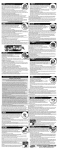
See the Service Parts illustration for kit contents.
Additional Parts Required
The following items must also be replaced when performing
this installation.
• (1) Canopy gasket, part number 61402-02.
• (10) Screws, self-sealing, Torx®, part number 1311D.
• (1) “O”-ring, part number 11380
These items are available from any Harley-Davidson dealer.
NOTE
This instruction sheet references Service Manual information. A Service Manual for your model motorcycle is required
for this installation and is available from any HarleyDavidson Dealer.
Installation
Removing the Old Sending Unit
1WARNING
To prevent accidental vehicle start-up, which could
cause death or serious injury, disconnect negative (-)
battery cable before proceeding. (00048a)
1. Refer to the Service Manual and follow the instructions
given to remove the seat and disconnect the negative
battery cable. Retain all seat mounting hardware.
1WARNING
When servicing the fuel system, do not smoke or allow
open flame or sparks in the vicinity. Gasoline is
extremely flammable and highly explosive, which could
result in death or serious injury. (00330a)
2. See the FUEL LEVEL SENDER (CARBURETED or
FUEL INJECTED) instructions for your model in the
Service Manual. Drain the fuel tank, then remove the
canopy and the attached fuel-level sending unit.
1WARNING
Thoroughly clean and dry the canopy and fuel-level
sender assembly in a well-ventilated area before drilling
the assembly. Failure to clean and dry the assembly in a
well-ventilated area could cause a fire, resulting in death
or serious injury.
3. In a well-ventilated area, use an evaporative solvent
such as a brake cleaner, and compressed air to thoroughly clean the canopy and sending unit assembly.
4. See FUEL LEVEL SENDER, REMOVAL in the Service
Manual to disassemble the fuel-level sending unit from
the support arm on the underside of the canopy. Retain
the 3-way connector from the old sending unit.
5. For fuel injected models: See the Service Parts illustration. Obtain the new fuel-level sending unit (1) from
the kit.
For carbureted models: See the Service Parts illustration. Obtain the new fuel-level sending unit (1) from the
kit. Cut the black wire coming from the 2-way connector
as close as possible to the splice inside the wire loom.
Pull the connector, along with the attached orange wire
and socket terminal out of the loom and discard it.
Installing the New Fuel-Level Sending Unit
6. See FUEL LEVEL SENDER, INSTALLATION in the
Service Manual to assemble the new sending unit
• For fuel injected models: to the fuel pump housing,
using the screw (3) from the kit.
• For carbureted models: to the support arm on the
canopy, using the blind rivet (2) from the kit.
7. Insert the terminals from the new fuel-level sender into
the 3-way connector saved in Step 4.
• Insert the black wire into chamber 3 (marked “• • •”).
• Insert the yellow wire into chamber 2 (marked “• •”).
• For fuel injected models: Insert the orange wire into
chamber 1 (marked “•”).
For carbureted models: Chamber 1 (marked “•”)
remains empty.
8. Refer to CANOPY CONNECTOR/ O”-RING in the
Service Manual to replace the existing “O”-ring with a
new “O”-ring (purchased separately).
9. See the FUEL LEVEL SENDER, CANOPY INSTALLATION instructions for your model in the Service
Manual. Install the 3-way connector into the receptacle
on the top of the canopy.
1 of 2
10. Attach the spade connector to the tab on the underside
of the canopy.
11. Manually cycle the float assembly through a few full
cycles, from empty to full, to ensure that the float contacts function correctly. View the fuel gauge while moving the float.
12. Install the canopy and attached fuel-level sending unit,
using a new canopy gasket and ten new Torx screws
(purchased separately).
14. Fill the fuel tank with fuel and check for leaks.
15. Refer to the Service Manual and follow the instructions
given to re-attach the negative battery cable and install
the seat.
1WARNING
After installing seat, pull upward on front of seat to be
sure it is in locked position. While riding, a loose seat
can shift causing loss of control, which could result in
death or serious injury. (00070a)
13. Fasten the wiring in the same way as the original installation with the new cable tie (4) from the kit.
®
Service Parts
Part No. 75229-03, 75241-03
Date 04/04
Fuel-Gauge Sending Unit
i02499b
B
A
1
1
4
2
FLHR, FLHRS,
FLHT, FLHTC
3
FLHPI, FLHPEI, FLHRI,
FLHRCI, FLHRSI, FLHTI,
FLHTCI, FLHTCUI,
FLHTPI, FLTRI
Kit 75229-03: Fuel-Level Sending Unit Kit (FLHT, FLTR, shown):
Kit 75241-03: Fuel-Level Sending Unit Kit (FLHR, FLHP):
Item
1
2
3
4
Description
Fuel-gauge sending unit †
Blind rivet
Screw, truss head Torx®, K50-2.24 x 17.25 mm
Cable strap
Part No.
Not sold separately
8704
1314
10065
†NOTE
The sending units in these kits were designed for fuel-injected models, and must be modified
to fit carbureted applications. See illustration items A and B, and Step 5 in the instructions.
Item
A
B
-J03178
Modification for carbureted applications
Cut the black wire as close as possible to the splice.
Pull the orange wire and connector out of the loom and discard.
2 of 2