1
Professional Shop Manual
Compact Hydraulic Log Splitters
NOTE: These materials are for use by trained technicians who are experienced in the service and repair of outdoor power
equipment of the kind described in this publication, and are not intended for use by untrained or inexperienced individuals.
These materials are intended to provide supplemental information to assist the trained technician. Untrained or inexperienced individuals should seek the assistance of an experienced and trained professional. Read, understand, and follow all
instructions and use common sense when working on power equipment. This includes the contents of the product’s Operators Manual, supplied with the equipment. No liability can be accepted for any inaccuracies or omission in this publication,
although care has been taken to make it as complete and accurate as possible at the time of publication. However, due to
the variety of outdoor power equipment and continuing product changes that occur over time, updates will be made to these
instructions from time to time. Therefore, it may be necessary to obtain the latest materials before servicing or repairing a
product. The company reserves the right to make changes at any time to this publication without prior notice and without
incurring an obligation to make such changes to previously published versions. Instructions, photographs and illustrations
used in this publication are for reference use only and may not depict actual model and component parts.
© Copyright 2008 MTD Products Inc. All Rights Reserved
MTD Products Inc - Product Training and Education Department
FORM NUMBER - 769-04216
07/2008
Table of Contents:
Compact Hydraulic Log Splitter Manual
Chapter 1: Introduction ........................................................................................... 1
Professional Shop Manual Intent.......................................................................... 1
Safety ................................................................................................................... 2
Fasteners .............................................................................................................. 3
Assembly Instructions ........................................................................................... 3
Product Description .............................................................................................. 4
Understanding the Model Number........................................................................ 4
Chapter 2: Engine Maintenance ............................................................................. 5
Sparkplugs ............................................................................................................ 5
Air Filters .............................................................................................................. 6
Oil ......................................................................................................................... 7
Fuel....................................................................................................................... 9
Fuel Filter............................................................................................................ 10
Valve lash ........................................................................................................... 11
Flywheels ............................................................................................................ 12
Chapter 3: Hydraulic Diagnosis ............................................................................ 13
Overview ............................................................................................................. 14
Understanding the Hydraulic Flow ...................................................................... 15
Checking the Pump ............................................................................................ 17
Checking the Control Valve and Cylinder........................................................... 22
What to do About Failures .................................................................................. 23
System Drawings ................................................................................................ 24
Chapter 4: Components ......................................................................................... 27
Drive belt ............................................................................................................ 27
Belt Failure Chart................................................................................................ 28
Engine Replacement .......................................................................................... 30
Pump Replacement ............................................................................................ 31
Control Valve Replacement................................................................................ 33
Beam Replacement ............................................................................................. 36
Cylinder Replacement ........................................................................................ 38
Torque Spec. Chart ............................................................................................ 39
Chapter 5: Cylinder Rebuild .................................................................................. 41
Cylinder Identification .......................................................................................... 41
E-Type Cylinder Rebuild...................................................................................... 42
X-Type Cylinder Rebuild...................................................................................... 47
INTRODUCTION
CHAPTER 1: INTRODUCTION
Professional Service Manual Intent: This manual is intended to provide service dealers with information that will
help them maintain and repair the MTD compact log splitter.
Disclaimer: The information contained in this manual is correct at the time of writing. Both the product and the information about the product are subject to change without notice.
About the text format
Certain flags and key words are used to indicate the nature of the text that accompanies them. They are as follows:
! CAUTION
CAUTION: Indicates a potentially hazardous situation that, if not avoided, may result in
minor or moderate injury. It may also be used to alert against unsafe practices.
! WARNING
WARNING: Indicates a potentially hazardous situation that, if not avoided, could result
in death of serious injury.
! DANGER
DANGER: Indicates an imminently hazardous situation that, if not avoided, will result in
death or serious injury. This signal word is to be limited to the most extreme situations.
NOTE: “NOTE” is used to point-out helpful information that may not fit as a step in a procedure.
1.
Numbered steps indicate specific things that should be done, and the order in which they should be done.
1a. Substeps will be lettered and nested within steps. Two or more substeps may be combined to describe
the actions required to complete a step.
•
Bullet points: Indicate sub-steps or points of interest, without implying order or relative importance.
Disclaimer: This manual is intended for use by trained, professional technicians.
•
Common sense in operation and safety is assumed.
•
In no event shall MTD be liable for poor text interpretation, or poor execution of the procedures described in
the text.
•
If the person using this manual is uncomfortable with any procedures they encounter, they should seek the
help of a qualified technician.
1
INTRODUCTION
Safety
This Service Manual is meant to be used along with the Operator’s Manual. Read the Operator’s Manual and familiarize yourself with the safety and operational instructions for the equipment being worked on. Keep a copy of the
Operator’s Manual for quick reference. Operator’s manuals may be viewed for free at the brand support website. It
will be necessary to have the complete model and serial number for the equipment.
•
Be prepared in case of emergency:
! CAUTION
Keep a fire extinguisher nearby
Keep a first aid kit nearby
Keep emergency contact numbers handy
•
Replace any missing or damaged safety labels on shop equipment.
•
Replace any missing or damaged safety labels on equipment being serviced.
•
Grooming and attire:
! CAUTION
Do not wear loose fitting clothing that may become entangled in equipment.
Long hair should be secured to prevent entanglement in equipment.
! WARNING
Jewlery is best removed.
•
Protective gear: includeds, but is not limited to
Clear eye protection
while working around any machinery
Protective gloves
where necessary
Armored footwear
when working around any machinery
Hearing protection
in noisy environments
Chemically resistant gloves
Respirator
•
when working with chemicals or solvents
when working with chemical or solvents
Apropriate tinted eye protection
when cutting or welding
Fame resistant headgear, jacket, chaps
when cutting or welding
Remember that some hazards have a cumulative effect. A single exposure may
cause little or no harm, but continual or repeated exposure may cause very serious
harm.
•
Clean spills and fix obviously dangerous conditions as soon as they are noticed.
•
Lift and support heavy objects safely and securely.
•
Be aware of your surroundings and potential hazards that are inherent to all power
equipment. All the labels in the world cannot protect a tecchnician from an instant of
carelessness.
•
Hydraulic fluid under high pressure can be dangerous. A high-pressure hydraulic
fluid leak or spray can penetrate the skin. If this happens, seek immediate medical
attention to reduce the risk of blood poisoning leading to death or limb amputation.
•
2
! WARNING
Exhaust fumes from running engines contain carbon monoxide (CO). Carbon monoxide is a colorless odorless gas that is fatal if inhaled in sufficient quantity. Only
run engines in well ventilated areas. If running engines indoors, use an exhaust
evacuation system with adequate make-up air ventilated into the shop.
! CAUTION
! CAUTION
! DANGER
! DANGER
INTRODUCTION
Fasteners
•
The fasteners used on the equipment described in this manual, and the engine that powers it are a combination of metric and fractional inch. For this reason, wrench sizes are frequently identified in the text, and measurements are given in U.S. and metric scales.
•
If a fastener has a locking feature that has worn, replace the fastener or apply a small amount of releasable
thread locking compound such as Loctite® 242 (blue).
•
Some fasteners like cotter pins are single-use items that are not to be reused. Other fasteners such as lock
washers, retaining rings, and internal cotter pins (hairpin clips) may be reused if they do not show signs of
wear or damage. This manual leaves that decision to the judgement of the technician.
Assembly instructions
•
Torque specifications may be noted in the part of the text that covers assembly. They may be summarized in
tables along with special instructions regarding locking or lubrication. Whichever method is more appropriate
will be used. In many cases, both will be used so that the manual is handy as a quick-reference guide as well
as a step-by-step procedure guide that does not require the user to hunt for information.
•
Lubricant quantity and specification may be noted in the part of the text that covers maintnenace, and again
in the section that covers assembly. They may also be summarized in tables along with special instructions.
Whichever method is more appropriate will be used. In many cases, the information will be found in several
places in the manual so that the manual is handy as a quick-reference guide as well as a step-by-step procedure guide that does not require the user to hunt for information.
•
The level of assembly instructions provided will be determined by the complexity of reassembly, and by the
potential for damage or unsafe conditions to arise from mistakes made in assembly.
•
Some instructions may refer to other parts of the manual for subsidiary procedures. This avoids repeating the
same procedure two or three times in the manual.
3
INTRODUCTION
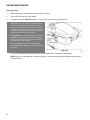
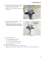
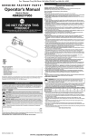
The Compact logsplitter
The compact logsplitter was designed to be useful where a
full-size logsplitter is not conventient to transport.
See Figure 1.0.
•
It can be lifted into the back of a car or truck for transport, weighing about 165lbs. (75 Kg.).
•
It can be easily moved by a single person.
•
It colapses into a small package that can be stored in
limited space.
Figure 1.0
Understanding model and serial numbers
The model number of a the compact log splitter described in this manual is 24AA5DMK029.
This manual is likely to carry useful information for a range of similar logsplitters that may carry a variety of MTD and
private brand names. The break down of what the model number means is as follows:
•
24A - - - - - - - - indicates that this is a log splitter
•
- - - A5 - - - - - - indicates the tank size and style
•
- - - - -D - - - - - indicates the tonnage
•
- - - - - - MK- - - indicates the engine
•
- - - - - - - - 029 indicates the customer
The serial number is 1J056G10005. The serial number reads as follows:
•
1...........................engineering level
•
..J.........................month of production (J = October)
•
.....05....................day of the month
•
.........6..................last digit of the year
•
...........G................plant it was built in
•
..............1.............assembly line number
•
.................0005.....number of unit built
Additional technical and service information may also be available to our company authorized service center personnel through our company corporate offices, regional parts distributors and regional service center field support personnel. Please contact the designated support office in your area or our corporate offices directly should further
service information be needed.
MTD Products LLC
P.O. Box 368022
Cleveland, OH 44136
Telephone: (800) 800-7310
www.mtdproducts.com
4
ENGINE MAINTENANCE
CHAPTER 2: ENGINE MAINTENANCE
The compact log splitter comes with an engine produced by MTD.
Refer to manual number 769-03354A for complete engine repair procedures.
MAINTENANCE
This Chapter covers the MTD engine, but the general information applies to most outdoor power equipment.
As the saying goes “an ounce of prevention is worth a pound of cure” the same can be said about preventive maintenance on outdoor power equipment. By changing the spark plug, air filter, and oil in annual intervals many failures
can be avoided. Sometimes just clearing off yard debris that has collected while in use can make the difference
between a properly running piece of equipment or a failure.
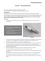
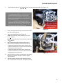
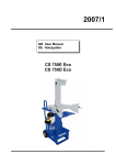
Spark plugs
1.
The spark plug used in the MTD engine is a Torch model F7RTC gapped to .024”-.032” (.60-.80 mm).
See Figure 2.1.
• Champion RN14YC or NGK BPR4ES are
physically similar but do not match the F7RTC
in exact specification
• This difference in specifications will effect performance and emissions.
• MTD recommends that only the torch F7RTC
plug be used in MTD engines.
Figure 2.1
2.
The wear rate of the spark plug will vary with severity of the engine’s use. If the edges of the center electrode
are rounded-off, or other apparent wear / damage occurs, replace it before the engine fails to start.
3.
Cleaning the spark plug: MTD does not recommend cleaning spark plugs.
•
Use of a wire brush may leave metal deposits on the insulator that shorts-out the spark plug, killing the spark.
•
Use of abrasive blast for cleaning may cause damage to ceramic insulator or leave blast media in the
recesses of the spark plug. When the media comes loose during engine operation, severe and non-warrantable engine damage may result.
4.
Inspection of the spark plug can provide indications of the operating condition of the engine.
•
The presence of light tan colored deposits on insulator and electrodes is normal.
•
Dry, black deposits on the insulator and electrodes indicate an over-rich fuel / air mixture (too much fuel or not
enough air)
•
Wet, black deposits on the insulator and electrodes indicate the presence of oil in the combustion chamber.
•
Heat damage (melted electrodes / cracked insulator / metal transfer deposits) may indicate detonation.
•
A spark plug that is wet with fuel indicates that fuel is present in the combustion chamber, but it is not being
ignited.
5
ENGINE MAINTENANCE
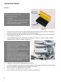
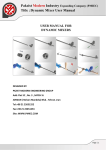
Air filters
Pleated-Paper
Element
Generally, air filters come in two types:
• Pleated-paper element
• Foam plastic
• Sometimes a combination of the two will be used
• The MTD engine uses a foam pre-filter and a
pleated paper element together.
Foam Pre-Filter
Figure 2.2
1.
The main function of the air filter is to trap air-borne particles before they reach the carburetor. Dirt ingested
through the carburetor can cause catastrophic internal engine damage.
2.
The air filters used on the MTD engine are designed to prevent particles larger than 3-5 micron from passing
into the engine. See Figure 2.2.
3.
The filter should be checked on a regular basis. Generally several times in a season, or when a change in
engine performance becomes noticable. See Figure 2.3.
Air filter cover
• Never use compressed air on a paper air filter.
Compressed air will remove the tiny fibers that
catch the dirt carried by the air. Without these
fibers the filter is useless.
Air filter location
• When drying a foam filter, either squeeze it inside
of a paper towel, or let it air dry. DO NOT wring it
because the filter will tear.
• Always check with factory specification before
servicing / replacing any engine components.
• Generally, if a foam pre-filter rides directly against
a paper filter element, the pre-filter should not be
oiled. If the two are separated by a mesh screen,
the pre-filter should be lightly oiled.
Figure 2.3
4.
Typically an ar filter should be changed before every season.
5.
If a foam air pre-cleaner is dirty and not in to bad of condition it can be cleaned and reused. The paper pleated
filters can be shaken or lightly tapped to free the debris from the filter.
6.
Foam pre-filters can be washed in warm soapy water.
7.
Before installing any foam filter after washing, it needs to be thoroughly dry.
.
6
ENGINE MAINTENANCE
Oil type and capacity
•
SAE 10W-30 oil with a SF/CD API rating is recommended for most operating conditions up to 97° F(36° C.).
See tables 1 & 2
•
The oil capacity is 17.0 fl.oz (0.5 liters).
•
Check the oil level before each use.
•
Change the oil every 25 hours, or more frequently in severe operating conditions.
Severe operationg condtions include:
high ambient temperature
dusty conditions
high load use in exceptionally thick grass.
•
Synthetic oil is a suitable alternative, but it does not extend service intervals.
NOTE: MTD recommends using petroleum-based oil during the break in period to ensure proper piston ring
break-in.
Table 1: Single Viscosity Oils
SAE 10W
SAE 20W
SAE 20
SAE 30
SAE 40
Celsius
-30
Farenheit
-20
-20
-10
0
0
20
10
40
20
60
30
80
40
100
Table 2: Multi Viscosity Oils
20W-40
20W-50
15W-40
15W-50
10W-40
10W-30
Celsius
-30
Farenheit
-20
-20
-10
0
20
0
10
40
20
60
30
80
40
100
7
ENGINE MAINTENANCE
Checking the oil
1.
When checking the oil thread the dip-stick out of the engine.
2.
Clean the oil off of the tip of the dipstick.
3.
Re-insert the dipstick without threading it in to get the oil level reading. See Figure 2.4.
• Synthetic vs. Petroleum based oil: To simply look
at synthetic oil and to compare it with Petroleum
based oil there is very little difference. However,
when you look at the two through a microscope it
is easy to see the difference. Synthetic is made up
of smaller molecules which allows the oil to get into
areas that petroleum based oil cannot.
• No oil additives or viscosity modifiers are recommended. The performance of a good oil meeting
the SF/ CD specifications will not be improved by
the addition of any oil additives.
• Some oil additives may cause severe and non
warrantable engine damage, constituting a lubrication failure.
Figure 2.4
.4
The oil level is determined by the lowest point on the dipstick that is completely covered with oil.
NOTE: If the oil is noticeably thin or smells of gasoline, a carburetor repair may be needed before the engine
can be safely run.
8
ENGINE MAINTENANCE
Changing the oil
! CAUTION
CAUTION: If the engine has been running, allow the engine to cool before doing any
maintenance work.
1.
Position a drain pan to collect the oil that is drained from the engine.
2.
Oil can be drained by removing the drain plug located at the base of the dipstick tube using a 10mm wrench.
See Figure 2.5.
• NOTE: Replace the drain plug sealing washer
with a n ew one to ensure that it does not leak.
• Tighten the drain plug to a torque of 84 in.- lbs.
(10 Nm) on installation.
Drain plug
Figure 2.5
3.
After the oil has drained, reinstall the oil drain plug.
4.
Refill the crankcase with the correct amount of oil.
5.
Breifly test-run the engine, and check for leaks.
6.
Dispose of the used oil in a legal and environmentally responsible manner.
Fuel
Today’s fuels contain mix of ingredients including oxygenators, detergents, benzene, and butane. These additives
help reduce emissions. The fuel make up can vary seasonally and geographically.
Alcohol used to oxygenate fuel creates a lot of problems for gasoline engines. The biggest problem is that alcohol
attracts and holds water. This corrodes the metal components of the fuel system, especially the carburetor.
Alcohol also does not produce as much heat as gasoline when burnt. This results in less power for the engine.
The stochiometric ratio of alcohol is differnet than gasoline. An engine tuned to run on gasoline will run artificailly
lean if too much alcohol is mixed with the fuel. This will cause hard starting and surging RPMs.
Fuel containing up to 10% alcohol is acceptable for MTD engines. Anything higher than that will result in performance
issues.
NOTE: E85 fuels are not to be used in any MTD engines.
•
Use clean, fresh fuel with a pump octane rating of 87 or greater.
•
Stale or out-of-date fuel is the leading cause of hard starting issues.
•
Pump octane ratings beyond 87 will not improve engine performance.
9
ENGINE MAINTENANCE
Fuel filters
Inset: fuel filter
• Dirty fuel can clog the carburetor and introduce
abrasive materials into the engine.
• To help prevent that, the MTD engine is equipped
with a fuel filter.
• MTD engines have a fuel filter installed in the fuel
tank barb. See Figure 2.6.
Fuel filter
Fuel tank
Figure 2.6
Valve lash
Valve lash can be checked and adjusted using the following steps:
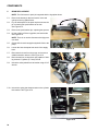
1.
If the engine has been run, allow it to cool thoroughly. Position the mower for easy access to the cylinder head.
2.
Disconnect the high-tension lead from the spark plug and ground it well away from the spark plug hole.
3.
Remove the spark plug using a 13/16” or 21mm wrench.
See Figure 2.7.
Spark plug hole
(plug removed)
NOTE: A flexible coupling or “wobbly” extension will make it
easier to remove the spark plug.
Valve cover
Muffler
High tension lead
Figure 2.7
4.
Remove the four bolts that secure the valve cover using a 10mm wrench, and remove the valve cover from the
engine.
NOTE: If care is used not to damage the valve cover gasket, it can be re-used.
5.
10
Slowly pull the starter rope until air can be heard coming out of the spark plug hole.
ENGINE MAINTENANCE
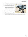
6.
Confirm that the piston is at Top-Dead-Center on the compression stroke. See Figure 2.8.
• The compression stroke can be distinguished
from the overlap stroke by the presence of air
pressure at the spark plug hole and the fact that
neither of the valves should move significantly on
the compression stroke.
• There is an automatic compression release
mechanism that “bumps” the exhaust valve as the
piston rises on the compression stroke. At TDC,
the exhaust valve should be fully closed.
Valves closed
(push rods slack)
Probe to confirm piston
is at top of travel on
compresion stroke
Figure 2.8
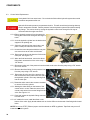
7.
8.
Check valve lash between each valve stem and rocker
arm using a feeler gauge.
Valve lash specifications: See Figure 2.9.
Intake valve lash (top valve) should be .003”-.005”
(.10 + .02mm).
Check lash here
Exhaust valve lash (bottom valve) should be .005-.007”
(.15 + .02mm).
9.
Use a 10mm wrench to loosen the jam nut and a
kkkk 14mm wrench to adjust the rocker arm fulcrum nut.
•
Tighten the rocker arm fulcrum nut to close-up the
clearance between the end of the valve stem and the
contact point on the rocker arm.
•
Loosen the rocker arm fulcrum nut to open-up the
clearance between the end of the valve stem and the
contact point on the rocker arm.
10.
Hold the fulcrum nut with a 14 mm wrench, and tighten
the jam nut to a torque of 89 in-lb. (10 N-m) using a
10 mm wrench.
11.
Double-check the clearance after tightening the jam
nut, to confirm that it did not shift. Re-adjust if needed.
Figure 2.9
11
ENGINE MAINTENANCE
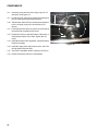
7.
Rotate the engine through several compression cycles:
•
Observe the movement of the valve gear.
•
Return the piston to TDC compression stroke and re-check the valve lash to confirm consistent movement of
the valve gear, including the slight bump to the exhaust valve from the automatic compression release.
8.
Clean-up any oil around the valve cover opening, clean the valve cover, replace the valve cover gasket if necessary.
9.
Install the valve cover, tightening the valve cover screws to a torque of 62 - 80 in-lbs (7-9 Nm).
10.
Install the spark plug.
Release the spring clamp securing the safety bail, start the engine and test run it long enough to confirm correct
operation.
ENGINE USE AND FLYWHEEL INFORMATION
The engine that powers the MTD log splitter is very similar to, but not the same as an engine used on MTD lawnmowers. The primary differences are in the flywheel and safety features. The logsplitter-spec. engine should never be
installed on a lawnmower.
! CAUTION
•
Lawnmower engines must comply with industry safety standards. When a safety bale is released, the blade
must stop within 3 seconds. The logsplitter engine is not equipped with the engine brake that is necessary to
meet this standard. If the lotgsplitter engine is mounted on a lawnmower, an unsafe condition will be created.
•
Lawnmower engines must comply with industry safety standards. Blade tip speed is regulated to 19,000 feet
per minute by ANSI B71.1-1984. The governor setting of the log splitter engine will exceed that speed on
some lawnmower applications.
•
Many lawnmower engines count on the fly-weight of the blade to create enough inertia to get the piston past
top-dead-center on the compression stroke when the engine is being started. Engine applications that do not
drive high-inertia implements may have heavy flywheels. Installing a lawnmower flywheel on a log splitter
engine may result in very dificult starting and violent starter rope jerk-back.
•
Replace any flywheel with any visible damage. Any cracks or broken fins can create a burst hazard. Do NOT
operate an engine with a damaged flywheel. Do NOT return an engin with a damaged flywheel to service.
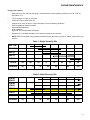
Table 3:
Item
12
Type
Spec.: U.S.
Spec.: metric
RPM
Engine speed
3,400-3,600 RPM
3,400-3,600 RPM
Spark plug
Torch F7RTC
Gap: .024”-.032”
Gap: .60mm-.80mm
Valve lash
Intake
.003”-.005”
.08mm-.13mm
Valve lash
Exhaust
.005”-.007”
.13mm-.18mm
Oil
SAE 10W-30, SG/SF or better
(most conditions)
17 fl.oz.
0.5 litres
Fuel
Minimum octane: 87 Maximum
alcohol: 10% by volume
0.32 gallons
1.2 litres
HYDRAULIC DIAGNOSIS
CHAPTER 3: HYDRAULIC DIAGNOSIS
1.
OVERVIEW
The main components of the compact log splitter are all fairly expensive. Hip-shot diagnosis will result in wasted time
and money for the dealer. Throwing wrong parts at a log splitter gets expensive fast.
The process of diagnosis is a process of developing and testing theories about the problem that caused the customer
to bring the log splitter in for repair.
To properly diagnose a problem with the hydraulic system of a log splitter;
1.
Get complete information from the customer;
1a. Make sure the customer understands how to operate the log splitter.
1b. Make sure the customer knows what the log splitter is supposed to be able to do.
1c. Get a thorough description of the problem the customer is having with the equipment
1d. Get as much maintenance history of the log splitter as possible.
2.
Understand the equipment;
2a. Know how each component works in the system.
2b. Know what symptoms each component might produce if it fails.
2c. Test the components against their specifications to identify the problem.
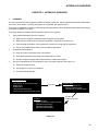
3.
Use your understanding of the equipment to work in a logical sequence; See Figure 3.1.
3a. Check the simple stuff first.
3b. Use symptoms to focus your attention.
3c. Test and eliminate theories.
Pump performance;
Wrong oil / low oil
Poor engine or drive performance
Slipping belt
Blocked vent
Low flow rate (bad pump)
Low pressure / flow droop (bad pump)
Pump O.K.
Cylinder;
External leaks;
(nipple, shaft seal, or bore-end seal)
Internal leaks (blow-by)
Mechanical bind (shaft)
Mechanical bind (beam)
Control valve;
Pressure relief too low
Pressure relief too high
Will not stay in return position
Pump O.K.
Control valve O.K.
Figure 3.1
13
HYDRAULIC DIAGNOSIS
4.
UNDERSTANDING THE HYDRAULIC FLOW
4.1.
It starts at the reservoir (tank). See Figure 3.2. See Figure 3.3.
Wedge
• The tank is built-into the beam of the logsplitter.
• The wedge is welded to the top of the tank / beam assembly.
Vent
• There is a pipe plug in the wedge end of the tank.
• Check the level of the hydraulic fluid, and add hydraulic
fluid through the plug.
Tank / beam
Fill port
• The tank must be vented. The vent is located on the
wedge, directly above the plug.
Figure 3.2
From control valve
• An elbow on the engine end of the tank feeds hydraulic
fluid directly to the pump.
• A straight fitting on the engine end of the tank, nearer to
the engine, provides a return path to the tank.
To pump
Figure 3.3
14
HYDRAULIC DIAGNOSIS
4.2.
The pump draws fluid from the tank, and forces it under pressure to the control valve.
See Figure 3.4.
Tank
• The pump is capable of producing 3,400 PSI (234 BAR)
at a pump speed of 3,600 RPM.
Pump
• The pump moves a nominal 2 GPM (7.6 L/M) at a
pump speed of 3,600 RPM
• The pump is single-stage.
• There is no relief valve in the pump.
• The pump is belt-driven from the engine.
• The pump delivers pressurized hydraulic fluid to the
control valve.
Fluid
flow
Figure 3.4
4.3.
The open-center control valve does four things:
See Figure 3.5.
Control lever
Low pressure
return hose
Regulate It regulates fluid pressure.
• If the pressure exceeds 3,400 PSI (232 BAR), the relief
valve opens, returning fluid directly to the tank.
• In any no-load condition, pressure should not exceed 300
PSI (20.4 BAR).
Forward It drives the ram toward the wedge.
Nipple
• In the forward position, the control valve directs pressurized fluid through the pipe nipple that supports it, to the
port at the base of the cylinder.
• This drives the piston down bore, displacing fluid from the
shaft side of the cylinder.
High pressure
from pump
High pressure to
shaft end of cylinder
Cylinder
Figure 3.5
• The control valve allows displaced fluid to leave the shaft
end of the cylinder through the high pressure hose, returning to the control valve.
• The control valve dumps displaced fluid back into the tank through the low presure hose.
Retract It draws the ram away from the wedge.
• In the retract position, the control valve sends fluid through the hose to the port at the shaft end of the cylinder.
• This drives the piston up the bore, displacing fluid from the base side of the cylinder.
• The control valve allows displaced fluid to leave the base end of the cylinder through the nipple, returning to the
control valve.
• The control valve dumps displaced fluid back into the tank through the low presure hose.
• The control lever is held in the retract position by a detent. When the piston bottoms-out, the build-up of pressure
of between 500 and 1,250 PSI forces the valve out of detent, returning it to neutral.tral.
Neutral In the neutral position, fluid from the pump is dumped directly back into the tank through the low pressure
hose.
15
HYDRAULIC DIAGNOSIS
4.4.
Cylinder See Figure 3.6.
Cylinder,
Ram end
• Both ports of the cylnder are connected to the control
valve.
Control valve
Cylinder,
Base end
• When pressure is applied to the port at the base of the
cylinder (through the nipple), the ram extends.
• When pressure is applied to the port at the shaft end of
the cylinder (through the flexible high-presssure hose),
the ram retracts.
Nipple
• When pressure is applied to one port, fluid from the
other port is forced back to the control valve by the
movement of the piston in the cylinder bore.
Pump
Figure 3.6
4.5.
Hoses: high pressure and low pressure
High-pressure
hose
• High-pressure hoses connect the pump to the control
valve and the control valve to the shaft end of the cylinder.
• High pressure means 3,500 PSI working pressure.
• Low pressure hoses connect the tank to the pump and
the control vave to the tank.
• The hose from the tank to the pump is molded.
• Hoses must not collapse under the suction pressure ot
the pump.
• Low pressure hoses are fastened with hose clamps.
Low-pressure
hoses
Figure 3.7
NOTE: The low pressure hose that supplies the pump carries fluid under suction. If it leaks, it will draw-in air,
but may leak very little fluid out. This entrained air will create cavitation in the pump. Poor pump performance
accompanied by whining or growling noises can indicate a leaky suction-side hose.
16
HYDRAULIC DIAGNOSIS
5.
CHECKING THE PUMP
Just because a hydraulic pump is not pumping well does not mean the pump is bad.
Before condemning parts or getting into deeper diagnosis, check the basics.
External factors that will effect pump performance include:
5.1.
Engine performance See Figure 3.8.
3,600 RPM
• The engine should be adjusted to run at 3,500 + 100
RPM. Check it with a tachometer.
• The engine must be in good state of tune: good spark
plug, clean air filter, fresh fuel, clean carburetor, correct
valve lash.
• The engine must be in good mechanical condition: good
compression.
• If the engine speed is set correctly, but it slows-down
excessively under load, there is an angine performance
issue.
• The engine performance issue must be fixed before
valid pump tests can be made.
Figure 3.8
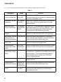
5.2.
Belt slippage See Figure 3.9.
Engine
• If the pump does not perform well, and the engine
shows no signs of laboring under load, check for belt
slippage.
• Belt slippage may be accompanied by unusual noises
or burning smells.
• Remove bottom cover from the bottom of the log splitter to reach the belt.
• Use only the correct MTD belt. The part number is
usually printed on the belt.
• When replacing a belt, check the hardware: The idler
pulley should spin freely and apply tension to the belt.
The engine and pump pulleys should be firmly connected to their shafts.
Idler pulley
(belt tensioner)
Pump
Figure 3.9
17
HYDRAULIC DIAGNOSIS
5.3.
Low fluid / wrong fluid See Figure 3.10.
• With the log splitter on level ground, remove the plug at
the wedge end of the tank to check the fluid.
• Check fluid cold. It expands when it gets hot.
• The logsplitter should contain 1.5 gallons (5.68 litres) of
hydraulic fluid.
• Use either Dexron III ATF or 10 Weight AW hydraulic
fluid. Do not mix the two
• If in doubt, drain it out; replace the fluid with known correct hydraulic fluid.
• Too little fluid will starve the pump.
• Too much fluid will slow performance and spill from the
vent.
Figure 3.10
Hot hydraulic fluid can cause burns. Do not check the fluid until the hydraulic system has
cooled to ambient temperature after use.
5.4.
Cold temperatures
• Hydraulic fluid gets thick at low temperatures; the splitter should not be used with hydrualic fluid temperature
below 20 deg. f. (-6.66 deg. c.)
• Hydraulic tests should be performed with the fluid warmed-up to 120 deg. f. (49 deg. c.) to get accurate results.
• When the fluid it too cold, pressure will be high and flow will be low.
• When the fluid is too cold, logsplitter operation will be sluggish.
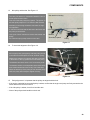
5.5.
Fluid not getting to the pump See Figure 3.11.
Checking fluid supply to pump
• If fluid is not reaching the pump, the log slitter will not
work
• Continued running with a dry pump wil destroy the
pump. This is not warrantable damage.
• To check the fluid supply to the pump: place a drain
pan under the pump, and disconnect the formed hose
that feeds the pump. Fluid should flow freely from it.
• Watch the formed hose that feeds the pump while the
ram is in motion. If the hose is collapsing, it will blockoff the supply of ffluid to the pump.
• Entrained air from a suction hose leak will cause a loss
of splitting force and a noisy pump.
Figure 3.11
18
HYDRAULIC DIAGNOSIS
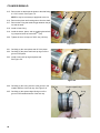
5.6.
Sealed tank vent See Figure 3.12.
• The tank vent is near the base of the wedge.
Tank vent
• The vent consists of a plastic plug with a felt washer; it
allows air to flow in and out of the tank.
• As the fluid moves from the tank to the cylinder, it draws
air in. As fluid moves from the cylinder back to the tank,
air is forced out of the tank.
• If the tank cannot “breath” through the vent, extending
the ram will form a vacuum in the tank.
• If the tank cannot “breath” through the vent, retracting
the ram will pressurize the tank.
• The ram will move through part of its’ stroke, then stop
as the vaccum or pressure builds.
Figure 3.12
If the tank is pressurized by a blocked vent, relieve the pressure by extending the ram before
attempting to remove the plug. Removing the plug from a pressurized tank can launch a dangerous projectile.
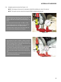
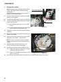
5.7.
To check the tank vent: See Figure 3.13.
5.7. a. Remove the the threaded plug from the tank,
and carefully pry-out the tank vent plug.
Checking vent port
5.7. b. Blow compressed air, regulated to about 30
PSI (2 Bars), into the threaded check-fill port.
5.7. c. Check the vent port. A flow of air that is equal
to the flow going into the check/fill port should
be coming out of the vent port.
Figure 3.13
19
HYDRAULIC DIAGNOSIS
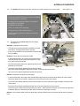
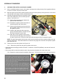
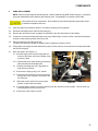
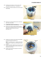
5.8.
To test the pump: See Figure 3.14.
5.8. a. With the engine turned-off, relieve hydraulic
pressure from the system by moving the lever
on the control valve through it’s full range of
travel.
Flow meter
Snubber valve
Pressure
gauge
5.8. b. Connect the flow and pressure test gauge set
(P/N 759-3742) between the pump and the
control valve.
• The pressure gauge should be nearest the pump.
• The flow meter should be nearest the control valve.
5.8. c. Confirm that the snubber valve on the test
gauge set is fully open and all connections are
tight.
Install gauge set
in this line
Figure 3.14
Hydraulic fluid under high pressure can be dangerous. A high-pressure hydraulic fluid leak or
spray can penetrate the skin. If this happens, seek immediate medical attention to reduce the
risk of blood poisoning leading to death or limb amputation.
If a hydraulic fluid leak develops at any time during testing or operation of the log splitter, turn it off
and repair the leak before any further work is done.
5.8. d. Start and run the log splitter to warm-up the fluid and check the test set
connections for leaks. Cycle the ram 12 times to purge air from the hydraulic system.
5.8. e. Read the flow meter. The reading should be a minimum of 1.85 GPM (7 LPM).
NOTE: The metric scale (Liters Per Minute) provides a more usable flow reading than the U.S. scale (Gallons
Per Minute) for this test.
Do NOT exceed 3,200 PSI (220 Bars). This test is performed up-stream of the relief valve in the
log splitter hydraulic system, rendering the relief valve ineffective during the test. Over-loading
the system will damage the pump.
Slowly close the snubber valve to build 2,000 PSI (220 Bars).
5.8. f. Note the reading on the flow meter.
5.8. g. IMMEDIATELY open the snubber valve, then turn-off the engine.
20
HYDRAULIC DIAGNOSIS
5.9.
Interpreting the test results: See Figure 3.15.
NOTE: The change in flow rate from unloaded to 2,000 PSI (138 Bars) is called “Flow droop”.
NOTE: The engine governor should hold engine RPMS constant during the test.
Base-line
flow:
~8 LPM
• If the pump fails to produce the base-line flow rate {1.85
GPM (7 LPM)}, but engine RPM is 3,500, there is
aproblem with the drive system (belt and pulleys) or the
pump.
Base-line
flow:
No pressure
• Flow droop should be less than .26 GPM (1 LPM).
• If flow droops more than .26 GPM (1 LPM), and the
engine RPM falls, there is an engine problem
• .If pressure fails to build, there is a problem with the
drive system (belt and pulleys) or the pump.
Figure 3.15
• If flow drops more than .26 GPM (1 LPM), the engine
RPM does not change, and the engine exhaust note
does not change, there is a problem with the drive system (belt and pulleys) or the pump.
• If base-line flow is 1.85 GPM (7 LPM), pressure builds
to 2,000 PSI (138 Bars) when the snubber valve is
closed, and pressure droop is less than .26 GPM (1
LPM), the pump, engine, and drive are working properly.
2,000 PSI
(138 Bars)
1.85 GPM
7 LPM
• To identify drive problems remove the bottom cover and
examine the belt and pulleys.
Figure 3.16
21
HYDRAULIC DIAGNOSIS
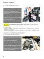
6.
CHECKING THE CONTROL VALVE AND CYLINDER
6.1.
After it is established that the engine, drive system, and pump are working correctly, if the log splitter still does
not work as it should, check the control valve.
6.2.
With the engine turned-off and hydraulic pressure relieved from the system by moving the lever on the control
valve through it’s full range of travel, proceed with the test.
6.3.
Install the test gauges between the log splitter control
valve and the fitting at the ram end of the hydraulic
cylinder. See Figure 3.17.
Control valve
Ram end of cylinder
6.3. a. Remove the test gauges from between the
pump and the control valve.
6.3. b. Reinstall the original hydraulic hose that connected the pump to the control valve.
6.3. c. Disconnect the hydraulic hose that runs from
the log splitter control valve to the ram end of
the hydraulic cylinder.
6.3. d. Install the test gauge set with the pressure
gauge nearest the cylinder connection and the
flow meter nearest the control valve.
6.3. e. Start and run the log splitter to warm-up the
Figure 3.17
fluid and check the test gauge set connections
for leaks. Cycle the ram 12 times to warm-up the fluid and purge air from the hydraulic system.
NOTE: The nipple that supplies fluid from the control valve to the base end of the hydraulic cylinder also supports the control valve. This makes it difficult to connect the test gauge set to the side of the hydraulic system
that extends the ram.
6.4.
Test the control valve and cylinder. See Figure 3.18.
6.4. a. Extend the cylinder fully using the log splitter control valve.
• As the ram reach the wedge, pressure will build to a maximum of 3,200 PSI (220 Bars), then the relief valve will
spill-off fluid.
• If the pressure fails to reach the maximum seen in the pump test, the problem lies in the control valve.
6.4. b. Retract the cylinder using the log splitter control valve. The flow meter will work in the retract direction.
• If the needle on the pressure gauge moved too fast to
get a good reading on the extension stroke, close the
snubber valve while retracting the cylinder. This will provide the same test results, but allows more control over
the rate of pressure build-up.
• If flow rate drops more than 1 LPM (.26 GPM) as pressure builds using the snubber valve, the log splitter control valve is leaking internally, and should be replaced.
• If the cylinder is retracted fully with the snubber valve
open, and the flow continues to register on the flow
meter as pressure builds, this indicates blow-by: the cylinder is leaking internally.
Figure 3.18
22
HYDRAULIC DIAGNOSIS
7.
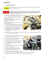
WHAT TO DO ABOUT FAILURES:
7.1.
If a pump is bad:
• Replace the pump. The pump is not servicable.
• If the pump failed becuase of an external cause, identify and eliminate the cause.
NOTE: Any disassembly of the pump WILL VOID THE WARRANTY. Do not take the pump apart if the repair
is warrantable.
7.2.
If the control valve is bad:
• If the repair is warrantable, replace the control valve.
NOTE: Any disassembly of the control valve WILL VOID THE WARRANTY. Do not take the control valve
apart if the repair is warrantable.
• If the relief valve is set too high or too low, and the control valve repair does not fall within the warranty policy, it
may be adjusted.
7.3.
If the cylinder is bad:
• If the cylinder is leaking at a seal, it may be repaired using a cylinder rebuild kit.
• If the cylinder is leaking at a welded seam, or has mechanical damage such as a bent shaft, replace the cylinder.
23
HYDRAULIC DIAGNOSIS
8.
SYSTEM DRAWINGS
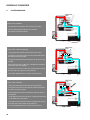
Control valve in Neutral
• The pump drives hydraulic fluid to the control valve.
• Fluid is shunted directly back to the reservoir
• No cylinder movement results
Reservoir
Figure 3.19
Control valve in Extend (splitting)
• The pump drives hydraulic fluid to the control valve.
• The spool in the control valve directs pressurized fluid to
the base end of the cylinder.
• The pressurized fluid forces the piston up the bore of the
cylinder.
• As the piston moves up the bore, it displaces fluid that is
on the ram side of the piston.
• The spool in the control valve also connects ports joining
the ram end of the cylinder to the reservoir.
• This allows displaced fluid to return to the reservoir.
Reservoir
Figure 3.20
Control valve in Retract
• The pump drives hydraulic fluid to the control valve.
• The spool in the control valve directs pressurized fluid to
the ram end of the cylinder.
• The pressurized fluid forces the piston down the bore of
the cylinder.
• As the piston moves down the bore, it displaces fluid that is
on the base side of the piston.
• The spool in the control valve also connects ports joining
the base end of the cylinder to the reservoir.
• This allows displaced fluid to return to the reservoir.
24
Figure 3.21
HYDRAULIC DIAGNOSIS
Relief in Neutral
• This drawing shows the relief valve in action with the control valve in neutral.
• The relief action is the same no matter what position the
control valve is in.
• If pressure builds beyond 3,500 PSI (in neutral this could
happen if the fluid is too cold), the relief valve opens, spilling fluid through a port that returns it to the reservoir.
Figure 3.22
25
HYDRAULIC DIAGNOSIS
26
COMPONENTS
CHAPTER 4: COMPONENTS
INTRODUCTION
This chapter covers the removal and replacement procedures for the wear items and major assemblies of the MTD
compact log splitter. Where applicable, there is also component service information.
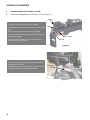
1.
DRIVE BELT
The belt that transfers power from the engine to the pump should provide years of service. The exact life depends on
the frequency and severity of use. If the belt fails prematurely, find and fix the problem that caused the failure before
returning the log splitter to the customer.
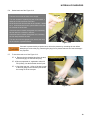
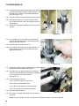
1.1.
Drive belt replacement:
Rear cover bolts
1.1. a. Allow the engine and hydraulic system to cool
before working on the log splitter.
1.1. b. Disconnect the high-tension lead from the
spark plug.
1.1. c. Empty the fuel tank, or seal the fuel tank cap
vent.
NOTE: The vent can be sealed by removing the cap,
placing a piece of plastic sheet or bag over the filler
neck of the fuel tank, and reinstalling the cap over the
plastic.
Front cover bolts
1.1. d. If the beam is not in the extended position
(ready for splitting), extend it and lock it.
Figure 4.1
1.1. e. Remove the three bolts that hold the back
edge of the belt cover to the frame using a 3/8”
wrench. See Figure 4.1.
1.1. f. Tilt the log splitter up on-end.
1.1. g. Remove the three bolts that hold the front
(beam side) edge of the belt cover to the frame
using a 3/8” wrench, and lift away the cover.
See Figure 4.1.
Spring
Belt
1.1. h. Relieve tension from the idler pulley.
See Figure 4.2.
1.1. i. Remove the belt.
1.1. j. Inspect the old belt, pulleys, and surrounding
area to determine the cause of the belt failure.
Idler pulley Idler bracket
1.1. k. If the failure was from any cause other than
the operational life of the belt, fix the problem.
1.1. l. Install the replacement belt by reversing the
removal procedure.
1.1. m. Remove the plastic from the fuel tank vent.
Figure 4.2
1.1. n. Re-connect the high-tension lead to the spark plug.
1.1. o. Test-run the log splitter before returning it to service.
27
COMPONENTS
1.2.
Likely causes of premature belt failure on the compact log splitter include: See Table 1:.
Table 1:
Description
Cause
Solution
Black dust inside
Cover or glazed belt
belt slipppage
wrong belt
Install the correct MTD or Arnold replacement belt.
The part number can be found in the Operator’s Manual, which is available on-line.
Glazed belt, may be
separating
belt slippage
oil on belt
Engine oil or hydraulic fluid are likely to be inside belt
cover. Clean-up the fluid, identify and fix the leak,
replace the belt.
Black dust inside
Cover or glazed belt,
belt slippage
improper belt
tension
2-3 lbs. (0.9-1.4 Kg.) force at the longest span of the
belt thould result in 3/8” (0.95 cm) deflection. Check
the condition of the spring that pulls the idler bracket.
Confirm that the idler bracket moves freely.
Narrow spot in belt,
vibration
over-load
Check for pump siezure, wrong fluid, exreme low temperature, or relief valve that is not working properly.
Belt chafed / abraded pulley problem
Pulley contact surface may be streaked
Check the condition and alignment of the pulleys.
Clean inside the belt chamber to prevent recurrence,
replace the belt, and install the belt cover.
Small radial cracks in
body of belt
age
Replace the belt, it is near the end of its service life.
Heat will accelerate the aging process.
Cords stretchedClean break in body
of belt
shock-load,
tensile failure
Check for pump siezure, wrong fluid, exreme low temperature, or relief valve that is not working properly.
Cords stretchedClean break in body
of belt
piercing
This is a form of foreign object damage where the belt
is partially cut. It sometime occurs when a belt is pried
onto the pulleys. The localized damage creates a
weak spot that acts as a stress riser until failure
occurs. Replace the belt
Clean break in belt
faulty belt
Belt fault will usually show-up almost immediately.
Replace the belt.
Foreign object or
small animal damage
Operation or
storage without belt cover
Clean inside the belt chamber to prevent recurrence,
replace the belt, and install the belt cover.
Heavy radial cracks
in belt
wrong belt
over-heat
A belt of too-heavy cross section has been used.
Internal friction from bending and straightening is
over-heating the belt.
28
COMPONENTS
1.3.
Idler pulley and bracket. See Figure 4.3.
• The idler pivot bracket is sandwiched between a shouldered spacer and the frame.
• One side of the idler pulley has a spacer. The spacer on
the idler pulley steps it out 1/8” from the idler bracket.
Idler bracket mounting
Frame
• Assembly in the wrong orientation will create an alignment probelm.
Spacer
• A 3/8-18 nut and bolt hold the bracket to the frame and
the pulley to the bracket.
• Use a pair of 9/16” wenches to remove the bracket and
pulley,
Bracket
Shouldered spacer
Pulley
• An extension spring keeps tension on the idler.
Figure 4.3
1.4.
To check belt alignment. See Figure 4.4.
Allen wrench
• If the engine pulley, pump pulley, and idler pulley are not
in the same horizontal plane, the belt will wear quickly.
Pump pulley
• Measure the distance from bottom top edge of the belt
to the bottom of the log splitter frame near each pulley.
• The distance should be about 1-3/8” at all three points.
• The distance itself is not as important as the fact that the
three measurements should not vary from each-other.
Straight edge
• When the bottom lip of the pulley is even with the pump
shaft, the pulley will usually be aligned correctly.
Figure 4.4
1.5.
Pulley alignment: it is important that the pulleys be aligned with the belt.
• If the engine crankshaft or pump shaft pulley is askew, confirm that the engine and pump are firmly mounted to the
frame and that the frame is not bent.
• If the idler pulley is askew, check for a bent idler arm.
• None of the pulleys should wobble on their axis.
29
COMPONENTS
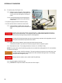
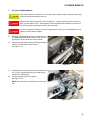
2.
ENGINE REPLACEMENT
NOTE: Complete engine service procedures can be
found in the Engine manual, publcation number
769-03354A.
Basic engine service procedures can be found in
chapter 2 of this manual: Engine.
2.1.
Allow the engine and hydraulic system to cool before
working on the logsplitter.
2.2.
Disconnect the high-tension lead from the spark plug.
2.3.
Disconnect the beam position safety switch from the
engine. See Figure 4.5.
Switch & block ground
Bullet connector
2.3. a. Disconnect the block ground using a 10mm
wrench.
2.3. b. Unplug the bullet connector that ties the switch
into the ignition module primary circuit.
2.4.
Empty the fuel from the fuel tank and the oil from the
crankcase.
2.5.
Remove the drive belt, as described in the drive belt
section of this chapter.
2.6.
Remove the drive belt pulley from the engine crankshaft using a 5/8” wrench. See Figure 4.6.
Figure 4.5
Pulley bolt
Crankshaft
pulley
NOTE: It may be necessary to remove the starter
housing and fan shroud to block the flywheel from
turning.
2.7.
Unbolt the engine from the frame using a 1/2”
wrench, and remove it from the logsplitter.
2.8.
Reverse the removal process to install the engine.
2.8. a. Tighten the engine mounting bolts to a torque
of 200-450 in-lbs. (22.5-50 N-m).
2.8. b. Tighten the crankshaft bolt to a torque of 23-27
ft-lbs. (31-36.5 N-m) .
2.9.
30
Engine to frame bolts
Figure 4.6
Fill the engine with fresh fuel and oil, and test-run the log splitter before returning it to service.
COMPONENTS
3.
PUMP REPLACEMENT
NOTE: If the pump fails within the warranty period, it will be called back by MTD Vendor Recovery. If the pump
has been disassembled, MTD will deny the warranty claim. Pumps MUST be returned to MTD intact.
Hot hydraulic fluid can cause burns. Do not drain the fluid until the hydraulic system has cooled
to ambient temperature after use.
3.1.
Allow the engine and hydraulic system to cool before working on the log splitter.
3.2.
Disconnect the high-tension lead from the spark plug.
3.3.
Remove the drive belt from the log splitter as described in the drive belt section of this chapter.
3.4.
Loosen the set screw that holds the pulley to the pump shaft using a 1/8” allen wrench, and slide the pulley as
far down on the shaft as possible. See Figure 4.8.
3.5.
Place a clean drain pan under the pump.
The drain pan should be capable of holding at least 2.5 gallons (9.5 liters) of fluid.
3.6.
Clamp (pinch) the supply hose that leads to the pump from the reservoir, and loosen the hose clamp that holds
the hose to the pump.
3.7.
Drain the system: See Figure 4.7.
3.7. a.Pull the supply hose off of the fitting that conClamp
nects it to the pump, and insert a length of tubSupply hose
ing into the hose.
3.7. b. Release the pinch clamp, allowing the draining
fluid to be directed into the drain pan.
3.7. c. Elevate the wedge end of the log splitter to
help drain the reservoir.
3.7. d. Remove the fill plug using a 1/2” wrench.
3.7. e. Disconnect the pressure hose from the pump
using a pair of 3/4” wrenches, and drain it into
the catch pan.
3.7. f. Move the control valve lever into the retract
position. A detent will hold it there.
Drain pan
Figure 4.7
3.7. g. If the log splitter cylinder is not fully retracted, push the ram back into the cylinder. This will force any
remaining fluid out of the pressure line.
3.7. h. Return the control valve to center.
31
COMPONENTS
3.8.
3.9.
Unbolt the pump from the frame using a pair of 1/2”
wrenches. See Figure 4.8.
1/8” allen wrench
Pump mounting bolts
Lift the pump off of the frame, slipping the pulley and
key off of the shaft as the pump comes up.
3.10. Take the flare elbow off of the old pump and transfer it
to the new pump using a 3/4” wrench and a 7/8”
wrench.
3.11. Fit the pulley and its drive key onto the pump shaft as
the new pump is installed to the frame.
3.12. Position the pulley so that the bottom of the pulley is
flush with the bottom of the shaft. Tighten the set
screw.
3.13. Install the belt and check alignment. Adjust the pulley
height if necessary.
3.14. Install the supply hose and pressure hose, and re-fill
the log splitter with fresh fluid.
3.15. Test-run the log splitter before returning it to service.
3.16. Examine the drained fluid for contamination.
32
Pump pulley
Figure 4.8
COMPONENTS
4.
CONTROL VALVE
Hot hydraulic fluid can cause burns. Do not drain the fluid until the hydraulic system has cooled
to ambient temperature after use.
Hydraulic fluid under pressure can penetrate the skin. This will cause blood poisoning that may
result in amputation or death. Relieve pressure from the hydraulic system before disconnecting
any fittings. This can be done by moving the hydraulic control lever through it’s full rage of travel
with the engine turned-off.
NOTE: If the control valve fails within the warranty period, it will be called back by MTD Vendor Recovery. If
the valve has been disassembled or tampered with in any way, MTD will deny the warranty claim.
Valves MUST be returned to MTD intact.
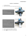
4.1.
Replacement Parts See Figure 4.9.
Lever
• The control lever bracket and link are the only available
service parts for the hydraulic control valve.
Screw
• The control valve lever is part # 947-0583
Bracket
• The control valve bracket is part # 718-0522
• The screws that hold the bracket to the control valve body
are part # 710-1503. Order 2.
• If the bracket is replaced, install new screws. They are
patch screws that are treated with thread locking compound.
• The link that connects the lever to the valve is a standard
chain link. It can be purchased locally as a #60 master
link with 3/4” pitch..
4.2.
Link
Figure 4.9
Adjusting pressure:
Control valve
4.2. a. Turn the engine off and relieve pressure from
the system.
4.2. b. Remove the plug that conceals the pressure
adjustment screw using a 5/8” wrench.
• The plug is located under the low pressure return line
from the valve to the tank.
• DO NOT remove the plug while the engine is running.
Adjustment screw
(plug removed)
4.2. c. Use the adjustment screw to set the relief
pressure. See Figure 4.10.
• Turn the adjustment screw in (clockwise) to raise the
relief pressure.
• Back the adjustment screw out (counter-clockwise) to
lower the relief pressure.
Figure 4.10
• Make adjustments in 1/4-turn increments.
• DO NOT set the relief pressure above 3,200 PSI (220 Bars).
4.2. d. Install the plug that conceals the adjustment screw, run and test the log splitter.
33
COMPONENTS
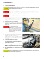
4.3.
Control Valve Replacement
Hot hydraulic fluid can cause burns. Do not drain the fluid until the hydraulic system has cooled
to ambient temperature after use.
Hydraulic fluid under pressure can penetrate the skin. This will cause blood poisoning that may
result in amputation or death. Relieve pressure from the hydraulic system before disconnecting
any fittings. This can be done by moving the hydraulic control lever through it’s full rage of
movement with the engine turned-off.
4.3. a.Relieve hydraulic pressure from the system by
moving the control lever through its full range of
travel.
Control valve
4.3. b. Lock the hydraulic cylinder into the bracket that
supports it for splitting use.
4.3. c. Clean the area around the control valve, and
place a catch pan under the control valve.
4.3. d. Loosen the hose clamps that hold the low pressure return hose to the valve and the tank.
Return line
4.3. e. Disconnect the hose and direct the fluid into the
catch pan. See Figure 4.11.
4.3. f. When the fluid has drained, remove the elbow
fitting that it connected to on the valve using a 11/8” wrench.
Figure 4.11
4.3. g. Disconnect valve end of the pressure hose that leads to the valve from the pump using a 7/8” wrench
and a 3/4” wrench.
4.3. h. Remove the elbow fitting (for the pressure line)
from the pump using a 3/4” wrench.
4.3. i. Disconnect the valve end of the pressure line
that connects the control valve to the ram end of
the hydraulic cylinder. Direct any draining fluid
into the catch pan.
Pressure hose
(from pump)
4.3. j. Rotate the entire control valve counter-clockwise
to remove it from the cylinder.
4.3. k. Holding the elbow fitting on the bottom of the
control valve in a vise, rotate the control valve
counter-clock-wise to remove the fitting from the
valve. See Figure 4.12.
4.3. l. Clean and inspect the hydraulic fittings removed
from the valve.
Figure 4.12
4.3. m. If suitable for reuse, install the elbow on the
bottom of the valve. Apply thread sealant such as Loctite 545TM to the threads of the fitting before installation.
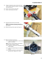
NOTE: Do not use PTFE (TeflonTM) tape to seal the threads on MTD log splitters. Tape flash may come off
inside the hydraulic system.
34
COMPONENTS
4.3. n. Transfer the grab handle from the old valve to the new valve using a 9/16” wrench.
4.3. o. Install the replacement valve to the log splitter
cylinder. Apply thread sealant such as Loctite
545TM to the threads of the nipple on the cylinder before installation. See Figure 4.13.
4.3. p. Install the return hose elbow and the pump
pressure line elbow onto the replacement control valve. Apply thread sealant such as Loctite
545TM to the threads of the fittings before
installation.
Control valve
4.3. q. Connect and tighten the pump pressure line.
4.3. r. Connect and tighten the return hose.
4.3. s. Refill the log splitter with fresh fluid or additional fluid of the same type drained during
valve removal.
Nipple (on cylinder)
Figure 4.13
4.3. t. Test-run the log splitter, checking for leaks and
confirming correct operation, then re-check the fluid level before returning the log splitter to service.
35
COMPONENTS
5.
BEAM REPLACEMENT
NOTE: The fluid reservoir (tank) is integrated with the log splitter beam.
5.1.
Remove the detent pin that secures the valve and
cylinder to the log splitter frame.
5.2.
Pry-off and dispose-of the push cap that secures the
pin connecting the push bracket to the ram.
See Figure 4.21.
5.3.
Remove the push bracket pin, capturing the spacers.
5.4.
Lift the cylinder off of the log splitter, and set it aside.
See Figure 4.14.
Cylinder
NOTE: There is no need to disconnect the high pressure hose.
5.5.
Clamp-off the hose that supplies hydraulic fluid to the
pump.
5.6.
Loosen the hose clamps at both ends of the supply
hose.
5.7.
Disconnect the hose from the pump, and connect a
suitable extension tube to it. See Figure 4.15.
5.8.
Drain the tank into a clean drain pan capable of holding at least 1.5 gallons (5.7 liters) of fluid.
5.9.
Unbolt the safety switch from its bracket using a 5/16”
wrench.
Figure 4.14
Supply
hose
Figure 4.15
5.10. Unhook the spring that keeps tension on the cylinder
lock bracket. See Figure 4.16.
Safety switch
Starter rope
Tension spring
Figure 4.16
36
COMPONENTS
5.11. Unbolt the cylinder lock bracket from the frame using
a 9/16” wrench. See Figure 4.17.
5.12. Remove the cylinder lock bracket.
5.13. Loosen the hose clamp that holds the low-pressure
return hose onto the fitting on the tank.
5.14. Disconnect the hose.
Cylinder lock
bracket
Figure 4.17
5.15. Unbolt the push bracket from the beam using a pair
of 9/16” wrenches. See Figure 4.18.
Push bracket
5.16. Support the tank side of the log splitter frame using
blocks or dimensional lumber.
Figure 4.18
5.17. Unbolt the beam from the frame using a pair of 9/16”
wrenches, and carefully remove it from the log splitter. See Figure 4.19.
Beam assembly
Support blocks
5.18. Transfer the support bracket rails, vent, and plug to
the replacement beam using a 1/2” wrench.
5.19. Install the replacement beam by reversing the steps
used to remove the old beam.
NOTE: Tighten horizontal beam-to-frame bolts before
tightening vertical beam-to-frame bolts.
Figure 4.19
37
COMPONENTS
6.
CYLINDER REPLACEMENT
Hot hydraulic fluid can cause burns. Do not drain the fluid until the hydraulic system has cooled
to ambient temperature after use.
Hydraulic fluid under pressure can penetrate the skin. This will cause blood poisoning that may
result in amputation or death. Relieve pressure from the hydraulic system before disconnecting
any fittings. Thic can be done by moving the hydraulic control lever through it’s full rage of
movement with the engine turned-off.
NOTE: There are two styles of hydraulic cylinder used
on the compact log splitter: E-type and X-type.
Control valve
Pressure line
• E-type cylinders can be identified by the notched lock ring
that secures the end cap.
• X-type cylinders can be identified by the presence of two
retaining bolts in the end cap.
• Both cylinders have the same part number and are completely interchangeable.
Return hose
6.1.
Allow the engine and hydraulic system to cool to ambient temperature before starting work on the log splitter.
6.2.
Relieve hydraulic pressure from the system by moving
the control lever through its full range of travel.
6.3.
Remove the control valve as described in the “Control
Valve Replacement” section of this chapter.
See Figure 4.20.
6.4.
Loosen, but do not remove the cylinder-end connection of the pressure line previously disconnected from the
the control valve, using an 11/16” wrench.
6.5.
Pry-off the push cap that holds the pin connecting the
push bracket to the ram. See Figure 4.21.
6.6.
Remove the push bracket pin, capturing the spacers.
6.7.
Slide the push bracket away from the ram.
6.8.
Direct the hose loosened in step 6.4 into a drain pan,
and manually extend the cylinder to empty the
hydraulic fluid from the ram end of the cylinder.
6.9.
Remove the hose.
6.10. Remove the detent pin, release the latch, and lift the
cylinder off of the log splitter.
Figure 4.20
Push bracket
Spacer
Push cap
6.11. Drain any residual fluid into the drain pan.
6.12. Install the replacement cylinder by reversing the
steps used to remove the old old one.
Figure 4.21
6.13. Fill the log splitter with fresh fluid matching the type
drained (10W hydraulic fluid is light-honey colored, Dexron III is dyed red for identification).
6.14. Test-run and purge the log splitter by cycling it 12 times before returning it to service.
38
COMPONENTS
Table 2:
Fastener
Torqe in in-lbs. or ft-lbs.
Torque in N-m
Engine mounting bolts
200-450 in-lbs.
22.5-50 N-m
Crankshaft pulley bolt
23-27 ft-lbs
31-36.5 N-m
Pump pulley set screw
70-80 in-lbs +loctite
242TM
8-9 N-m
Pump mounting bolts
144-168 in-lbs.
16-19 N-m
39
COMPONENTS
40
CYLINDER REBUILD
CHAPTER 5: CYLINDER REBUILD
1.
CYLINDER IDENTIFICATION
1.1.
There are two types of cylinder used on the Compact log splitter: E-type and X-type.
E-type cylinder
• The E-type cylinder uses a notched lock-ring to retain
the end-cap..
• End of ram is painted.
• Rebuild parts are not presently available.
• Replace complete for warrantable failures.
Lock ring
Figure 5.1
X-type cylinder
• The X-type pump uses two bolts and D-shaped plates to
retain the end cap..
• The end of the ram is chrome lated, but not painted..
• Rebuild kits are presently available.
• If the seals fail in a warrantable situation, the cylinder
will be repaired in the field.
• If seals fail outside of warranty, the cylinder can be
repaired in the field, at the customer’s expense.
• If hard parts are damaged, replace the cylinder complete
Retaining bolts
and washers
Figure 5.2
1.2.
In service, the cylinders are interchangeable as complete units.
1.3.
Seal kits are not interchangeable between the two cylinder types.
1.4.
Rebuild procedures for both cylinders are covered in this chapter.
41
CYLINDER REBUILD
2.
E-TYPE CYLINDER REBUILD
Hot hydraulic fluid can cause burns. Do not work on the cylinder until the hydraulic system has
cooled to ambient temperature after use.
Hydraulic fluid under high pressure can be dangerous. A high-pressure hydraulic fluid leak or
spray can penetrate the skin. If this happens, seek immediate medical attention to reduce the
risk of blood poisoning leading to death or limb amputation.
If a piece of hydraulic equipment develops a high pressure leak, turn it off immediately. Do not
operate it until the leak is repaired.
2.1.
Disconnect the hydraulic cylinder as described in the
CYLINDER REPLACEMENT section of this manual,
purging the fluid from both ends of the cylinder..
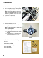
2.2.
Remove the cylinder from the log splitter.
2.3.
Heat the end cap lock ring to a pale straw yellow color,
and dab a bit of paraffin around the inside diameter of
the lock ring.
Heat and release end cap retainer
Use open flame with caution.
Keep at least 10’ (3.5 meters) from flamables.
Work in a well ventilated area wearing
appropriate protective gear: eye protection, flame retardant gloves, and flame
retardant clothing.
2.4.
Use a spanner or drift to turn the lock ring counterclockwise, loosening it. See Figure 5.3.
Figure 5.3
End cap
NOTE: The cylinder may be carefully placed back on
the log splitter for convenient support after the ring has
been heated.
2.5.
The threaded end cap will be exposed.
2.6.
Carefully drive the end cap back into the cylinder about
3/4” (1.5cm), exposing the heavy wire retaining ring
seated in the cylinder bore.
2.7.
Pry the retaining ring out of its groove. See Figure 5.4.
NOTE: Be careful not to scratch the bore of the cylinder.
2.8.
After the retaining ring is free, pull the shaft out of the
cylinder.
Retainer
Retaining ring
Figure 5.4
Do not use compressed air to force the piston out of the log splitter bore. Compressed air may
eject the piston with dangerous force.
42
CYLINDER REBUILD
2.9.
Prepare to separate the piston, shaft, and end cap
from the cylnder: support the cylinder in a soft-jawed
vise. See Figure 5.5.
2.10. Take the end cap retainer off the shaft.
2.11. Take the retaining ring off the shaft.
Figure 5.5
2.12. Clean the paint form the end of the shaft.
NOTE: The thickness of the paint on the shaft is
enough to jam the end cap, making it nearly impossible to remove.
Clean paint from
this section of shaft
2.13. Slide the end cap off of the shaft. See Figure 5.6.
Figure 5.6
2.14. Before proceeding: See Figure 5.7.
2.14. a. Inspect the shaft and piston to confirm that the
cylinder is rebuildable.
NOTE: A bend or surface damage on the shaft will
make the cylinder unfeasible to rebuild.
2.14. b. Inspect the cylinder bore for deformations and
surface damage.
2.14. c. Inspect the hydraulic fittings on the cylinder for
damage.
2.14. d. Inspect the cylinder for cracks around the fittings and welds. Magna-flux if in doubt.
Figure 5.7
43
CYLINDER REBUILD
2.15. Remove the nut that holds the piston to the shaft using
a 1-5/16” wrench. See Figure 5.8.
Shaft
Seal
Piston Nut
NOTE: It may be necessary to apply heat to the nut.
2.16. Remove the piston and backing sleeve from the shaft.
2.17. Remove the O-ring that seals the gap between the piston and the shaft.
2.18. Install a fresh O-ring.
2.19. Install the sleeve, piston, and nut, applying thread locking compound such as Loctite 262TM (red).
2.20. Tighten the nut to a torque of 100 ft.-lbs (136 N-m).
Figure 5.8
2.21. Carefully pry the outer piston seal off of the piston.
Outer seal
2.22. Carefully pry the piston seal back-up ring out of the
groove in the piston.
2.23. Install a new back-up ring and piston seal.
See Figure 5.9.
Back-up ring
Figure 5.9
2.24. Carefully pry the O-ring seal out of the groove in the
outside diameter of the end cap. See Figure 5.10.
End cap
Square-edged O-ring
2.25. Carefully pry the square-edged O-ring out of the
groove in the outside diameter of the end cap.
O-ring
Figure 5.10
44
CYLINDER REBUILD
2.26. Carefully pry the scraper out of the recess in the
threaded end of the end cap. See Figure 5.11.
Scraper
End cap
2.27. Carefully pry the blue internal seal out of its recess in
the end cap.
Figure 5.11
2.28. Warm the new scraper and blue seal in hot water to
make them more pliable.
2.29. Compress the new seal into the jaw of a 1-1/4” wrench,
so that it fits into the bore of the end cap,
2.30. Press the new seal into position with the lip facing
away from the threaded end of the end cap, then let it
expand into the groove that it will ride in.
See Figure 5.12.
Inset:
seal in hot
water
Seal
Figure 5.12
2.31. Install the new scraper in the recess in the threaded
end of the end gap. See Figure 5.13.
New scraper
New seal
NOTE: The scraper has an “L” shaped cross-section.
The leg of the L should face the threaded end of the
end cap.
2.32. Install a new square-edged O-ring in the groove, positioned at the edge of the groove that is nearer to the
threads on the end cap.
2.33. Install a new O-ring seal in the groove, next to the
square-edged O-ring.
Figure 5.13
45
CYLINDER REBUILD
2.34. Lubricate the piston with the same type of fluid that will
be used in the hydraulic system of the log splitter: 10W
hydraulic fluid, or Dexron III automatic transmission
fluid. See Figure 5.14.
End cap
Shaft
2.35. Insert the shaft and piston into the bore of the cylinder.
2.36. Lubricate the seals on the end cap using the same
type of fluid that will be used in the hydraulic system of
the log splitter.
2.37. Slip the end cap over the shaft and into the bore of the
cylinder.
Cylinder
Figure 5.14
2.38. Use a length of 1-1/2” iron pipe (or similar driver) to
drive the end cap into the bore, past the groove that
the wire snap ring locks into.
Snap ring
End cap
2.39. Install the snap ring. See Figure 5.15.
2.40. Pull the shaft and piston up to the top of the bore, so
that the piston moves the end cap back into place
against the snap ring.
Figure 5.15
2.41. Position the cylinder in the log splitter, with the gimble
pins latched into the cylinder lock bracket.
2.42. Install the lock ring; apply threadlocking compound
such as Loctite 262TM (red) to the threads, and tighten
it with a spanner or a hammer and drift.
See Figure 5.16.
2.43. Finish installing the cylinder:
2.43. a. Install the hydraulic control valve.
2.43. b. Connect the hydraulic lines.
2.43. c. Secure the cylinder using the detent pin.
2.43. d. Connect the push bracket to the shaft.
2.44. Re-fill the hydraulic system.
2.45. Run, purge, and test the log splitter before returning it
to service.
Figure 5.16
NOTE: Cycle the cylinder 12 times to purge air from the hydraulic system, then top-up the fluid.
46
CYLINDER REBUILD
3.
X-TYPE CYLINDER REBUILD
Hot hydraulic fluid can cause burns. Do not work on the cylinder until the hydraulic system has
cooled to ambient temperature after use.
Hydraulic fluid under high pressure can be dangerous. A high-pressure hydraulic fluid leak or
spray can penetrate the skin. If this happens, seek immediate medical attention to reduce the
risk of blood poisoning leading to death or limb amputation.
If a piece of hydraulic equipment develops a high pressure leak, turn it off immediately. Do not
operate it until the leak is repaired.
3.1.
Disconnect the hydraulic cylinder as described in the
CYLINDER REPLACEMENT section of this manual,
purging the fluid from both ends of the cylinder..
3.2.
Remove the two retaining bolts and D-shaped washers
from the end cap using a 10mm wrench.
See Figure 5.17.
Figure 5.17
3.3.
Carefully drive the end cap back into the cylinder about
3/4” (1.5cm), exposing the heavy wire retaining ring
seated in the cylinder bore.
3.4.
Pry the retaining ring out of its groove.
See Figure 5.18.
NOTE: Be careful not to scratch the bore of the cylinder.
Figure 5.18
47
CYLINDER REBUILD
3.5.
Reinstall the bolts in the end cap; just part way.
3.6.
Use the bolt heads to pry against, using the cylinder
lock bracket as a fulcrum to pry the end cap out of the
cylinder. See Figure 5.19.
Cylinder lock
bracket
NOTE: At this point, the shaft can be drawn most of
the way out of the cylinder, but it will hit the wedge at
the end of the beam before it comes all the way out.
3.7.
Remove the cylinder from the log splitter.
3.8.
Pull the shaft out of the cylinder.
3.9.
Slip the end cap off of the shaft.
End cap
Figure 5.19
3.10. Before proceeding: See Figure 5.20.
3.10. a. Inspect the shaft and piston to confirm that the
cylinder is rebuildable.
NOTE: A bend or surface damage on the shaft will render the cylinder unrebuildable.
3.10. b. Inspect the cylinder bore for deformations and
surface damage.
3.10. c. Inspect the hydraulic fittings on the cylinder for
damage.
3.10. d. Inspect the cylinder for cracks around the fittings and welds. Magna-flux if in doubt.
Figure 5.20
3.11. The cylinder rebuild kit consists of: See Figure 5.21.
• Instructions
• 2-piece piston ring seal (A)
A
B
C
D
• Piston-to-shaft O-ring seal (B)
• End cap outside diameter seal (C)
• End cap shaft seal (D)
• End cap shaft scraper (E)
Figure 5.21
48
E
CYLINDER REBUILD
3.12. Remove the set screw that locks the piston from rotating on the threaded shaft, using a 3mm allen wrench.
See Figure 5.22.
Set screw
Piston
3.13. Use a pin spanner, or improvise a pin spanner using a
pair of 5/16” bolts or dowel pins in the holes of the piston face, to unthread the piston from the shaft.
NOTE: It may be necessary to apply heat to the piston.
3.14. Replace the O-ring seal that goes between the piston
and the shaft.
3.15. Apply thread locking compound such as Loctite
(red) to the threads, and reinstall the piston.
Shaft
262TM
3.16. Tighten the piston to a torque of 140 ft-lbs (190 N-m).
3.17. Reinstall the set screw to lock the piston onto the shaft.
3.18. Carefully pry the outside diameter seals off of the piston.
Figure 5.22
Piston
2-part seal (in water)
3.19. Warm-up the new two-part piston seal set in hot water.
See Figure 5.23.
Hot water
Figure 5.23
3.20. Slip the black seal back-up into the groove on the piston.
3.21. Slip the blue outer seal into the groove, on top of the
seal back-up. See Figure 5.24.
Black seal
Blue seal
Piston
Figure 5.24
49
CYLINDER REBUILD
3.22. Carefully pry the O-ring seal out of the groove in outside diameter of the end cap. See Figure 5.25.
O-ring seal
Figure 5.25
3.23. Carefully pry the scraper out of the groove near the
outside face of the end cap. See Figure 5.26.
End cap
Old
scraper
Figure 5.26
3.24. Carefully pry the blue inner seal out of the groove in
the inside diameter of the end cap. See Figure 5.27.
End cap
Old seal
Figure 5.27
50
CYLINDER REBUILD
3.25. Soften the new shaft seal by soaking it in hot water just
before installation.
Wrench
3.26. Compress the new seal into the jaw of a 1-1/4” openend wrench. See Figure 5.28.
Seal
Figure 5.28
3.27. Install the seal: See Figure 5.29.
3.27. a. Position a socket or similar item with an outside diameter that is slightly smaller than the
inside diameter of the end cap in a vise, so that
when the end cap is placed over it, the top surface of the socket is level with the bottom land of
the O-ring groove.
End cap
Seal
3.27. b. Push the seal out of the wrench and into the
end cap, with the lip and black inner part of the
seal facing what would be the inside of the cylinder.
3.27. c. When the seal stops againns the socket, allow
it to expand into the groove.
Figure 5.29
3.28. Install the scraper: See Figure 5.30.
3.28. a. Slip the scraper into the groove near the
outer surface the end cap.
Hot water
Scraper
3.28. b. The lip of the scraper should face the outer
surface of the end cap.
NOTE: The outer surface of the end cap has the two
threaded holes in it.
Scraper
groove
Figure 5.30
51
CYLINDER REBUILD
3.29. Slip the end cap over the end of the shaft.
See Figure 5.31.
Seal protector
End cap
3.29. a. Lubricate the seal and scraper with the same
type of fluid that will be used in the log splitter
hydraulic system.
3.29. b. Insert a protector sleeve through the seal and
scraper to prevent damage during installation.
Shaft, supported in
a soft-jawed vise.
3.29. c. Push the end cap onto the shaft.
3.29. d. Install the new O-ring seal
3.29. e. Lubricate the shaft and the outside diameter
seal on the end cap with the same hydraulic
fluid that will be used in the log splitter hydraulic system.
Figure 5.31
3.30. Install the piston and end cap:
End cap
3.30. a. Insert the piston into the bore of the cylinder.
3.30. b. Press the piston down the bore.
3.30. c. Push the end cap into place.
End cap
Shaft
Piston
Cylinder
Figure 5.32
3.31. Use a length of 1-1/2” iron pipe (or similar driver) to
drive the end cap into the bore, past the groove that
the wire snap ring locks into.
3.32. Install the snap ring. See Figure 5.33.
Shaft
Snap ring
End cap
Figure 5.33
52
CYLINDER REBUILD
3.33. Pull the shaft and piston up to the top of the bore, so
that the piston moves the end cap back into place
against the snap ring. See Figure 5.34.
End cap
Bolt
NOTE: The bolts may be installed temporarily, for use
as pry-points.
Figure 5.34
3.34. Install the bolts and D-shaped washers to lock the
end cap in place. See Figure 5.35.
NOTE: Do not allow the washers to rotate so that
they drag against the shaft as the bolts are tightened.
They will scratch the shaft, destroying the cylinder.
Bolt
D-shaped washer
Figure 5.35
3.35. Finish installing the cylinder:
3.35. a. Install the hydraulic control valve.
3.35. b. Connect the hydraulic lines.
3.35. c. Secure the cylinder using the detent pin.
3.35. d. Connect the push bracket to the shaft.
3.36. Re-fill the hydraulic system.
3.37. Run, purge, and test the log splitter before returning it to service.
NOTE: Cycle the cylinder 12 times to purge air from the hydraulic system, then top-up the hydraulic fluid.
53