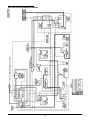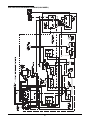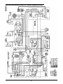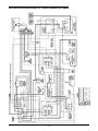
1
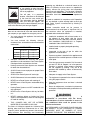
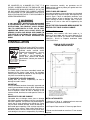
Users Manual
CUSTOM PASTA SYSTEM® GAS
SERIES 2009
READ AND SAVE THIS MANUAL FOR FUTURE REFERENCE.
RECORD THE MODEL AND SERIAL
SERIAL NO. ______________________________
NUMBERS OF THIS CUSTOM PASTA
MODEL NO. _____________________________
SYSTEM® IN THE SPACES PROVIDED.
KEEP THESE NUMBERS FOR FUTURE REFERENCE.
IMPORTANT: Keep a copy of your bill of sale. The date on the bill establishes the warranty period
should service be required. If service is performed, it is in your interest to obtain and keep all receipts.
Keating Custom Pasta Systems® are not intended for household use.
This Owner’s Guide provides specific operating and service instructions for your model. Use the
Custom Pasta Systems® only as instructed in this Service Manual.
CONTENTS:
SECTION I: INTRODUCTION
SHUTDOWN . . . . . . . . . . . . . . . . . . . . . . . . . . . . . . . . . . . . . . . . . . . . .8
GENERAL . . . . . . . . . . . . . . . . . . . . . . . . . . . . . . . . . . . . . . . . . . . . . . .1
DRAINING . . . . . . . . . . . . . . . . . . . . . . . . . . . . . . . . . . . . . . . . . . . . . . .9
STANDARD FEATURES . . . . . . . . . . . . . . . . . . . . . . . . . . . . . . . . . . . .1
CLEANING . . . . . . . . . . . . . . . . . . . . . . . . . . . . . . . . . . . . . . . . . . . . . . .9
MODEL VARIATIONS . . . . . . . . . . . . . . . . . . . . . . . . . . . . . . . . . . . . . .1
ELECTRONIC TIMERS . . . . . . . . . . . . . . . . . . . . . . . . . . . . . . . . .9-10
SAFETY PRECAUTIONS . . . . . . . . . . . . . . . . . . . . . . . . . . . . . . . . .1-3
SECTION IV: MAINTENANCE
SECTION II: INSTALLATION
WARRANTY REPAIRS . . . . . . . . . . . . . . . . . . . . . . . . . . . . . . . . . . . .10
DAMAGE DURING SHIPMENT . . . . . . . . . . . . . . . . . . . . . . . . . . . . .3
PREVENTIVE MAINTENANCE . . . . . . . . . . . . . . . . . . . . . . . . . . . . .11
DROP-IN CUTOUT/INSTALLATION . . . . . . . . . . . . . . . . . . . . . . . . . .3
CALIBRATION . . . . . . . . . . . . . . . . . . . . . . . . . . . . . . . . . . . . . . . . . . .12
POSITIONING . . . . . . . . . . . . . . . . . . . . . . . . . . . . . . . . . . . . . . . . . . . .4
LEVELING . . . . . . . . . . . . . . . . . . . . . . . . . . . . . . . . . . . . . . . . . . . . . . .4
RESTRAINING DEVICES . . . . . . . . . . . . . . . . . . . . . . . . . . . . . . . . . .4
SPECIFICATIONS . . . . . . . . . . . . . . . . . . . . . . . . . . . . . . . . . . . . . . . . .5
ELECTRICAL CONNECTION . . . . . . . . . . . . . . . . . . . . . . . . . . . . . . .6
GAS LEAK TESTING . . . . . . . . . . . . . . . . . . . . . . . . . . . . . . . . . . . . . .6
SECTION V: SERVICE DIAGNOSIS
WATER FILL AND SAFETY SHUT-OFF CIRCUIT BOARD
AND SENSOR CHECK . . . . . . . . . . . . . . . . . . . . . . . . . . . . . . . .11-12
GENERAL . . . . . . . . . . . . . . . . . . . . . . . . . . . . . . . . . . . . . . . . . . . . . .12
TROUBLE SHOOTING CHART . . . . . . . . . . . . . . . . . . . . . . . . .13-16
REPLACEMENT OF A & B BOARDS . . . . . . . . . . . . . . . . . . . . . . .17
CHECK GAS SUPPLY PRESSURE . . . . . . . . . . . . . . . . . . . . . . . . . .6
SPECIAL NOTICES . . . . . . . . . . . . . . . . . . . . . . . . . . . . . . . . . . . . . . .6
SECTION VI: PARTS LIST
CALIBRATION . . . . . . . . . . . . . . . . . . . . . . . . . . . . . . . . . . . . . . . . . . . .7
ORDERING PARTS . . . . . . . . . . . . . . . . . . . . . . . . . . . . . . . . . . . . . .18
WATER AND DRAIN CONNECTIONS . . . . . . . . . . . . . . . . . . . . . . .7
CONTROL PANEL ASSEMBLY . . . . . . . . . . . . . . . . . . . . . . . . .18-19
SECTION III: OPERATING THE PASTA SYSTEM
FILLING . . . . . . . . . . . . . . . . . . . . . . . . . . . . . . . . . . . . . . . . . . . . . . . . .7
GAS PASTA SYSTEM ASSEMBLY I . . . . . . . . . . . . . . . . . . . . . . . . .20
GAS PASTA SYSTEM ASSEMBLY II . . . . . . . . . . . . . . . . . . . . . . . .21
BASKET LIFT POWER SUPPLY BOX . . . . . . . . . . . . . . . . . . . . . . .22
LIGHTING . . . . . . . . . . . . . . . . . . . . . . . . . . . . . . . . . . . . . . . . . . . . . . .7
INDICATING LIGHTS . . . . . . . . . . . . . . . . . . . . . . . . . . . . . . . . . . . . . .8
SECTION VII: WIRING DIAGRAMS
COOKING . . . . . . . . . . . . . . . . . . . . . . . . . . . . . . . . . . . . . . . . . . . . . . .8
PASTA SYSTEM . . . . . . . . . . . . . . . . . . . . . . . . . . . . . . . . . . . . . . . . . .23
AUTO-LIFT GAS PASTA SYSTEM . . . . . . . . . . . . . . . . . . . . . . . .24-28
Keep this manual for training new personnel.
1-800-KEATING
www.keatingofchicago.com
p a r t # 0 1 876 6
gasPasta
0/1
This operating, installation, and service manual should be given to
the user. The operator of the Pasta System should be familiar with
the functions and operation of the cooker. This manual must be kept
in a prominent, easily reachable location near the Pasta System.
POST THIS LABEL IN A
PROMINENT LOCATION ON
YOUR UNIT
IMPORTANT
IN THE EVENT A GAS ODOR IS DETECTED, SHUT
DOWN UNITS AT MAIN SHUT OFF VALVE AND
CONTACT THE LOCAL GAS COMPANY OR GAS
SUPPLIER FOR SERVICE.
WARNING
FOR YOUR SAFETY
Do not store flammable
liquids near this or any
other appliance.
DO NOT STORE OR USE GASOLINE OR
OTHER FLAMMABLE VAPORS AND
LIQUIDS IN THE VICINITY OF THIS OR
ANY OTHER APPLIANCE.
WARNING IMPROPER INSTALLATION, ADJUSTMENT,
Gas
Burns
Shock
Improper installation
can cause damage,
injury or death.
ALTERATION, SERVICE OR MAINTENANCE
CAN CAUSE PROPERTY DAMAGE, INJURY
OR DEATH.
READ THE INSTALLATION,
OPERATING
AND
MAINTENANCE
INSTRUCTIONS THOROUGHLY BEFORE
INSTALLING
OR
SERVICING
THIS
EQUIPMENT.
Using any parts other than genuine, Keating of Chicago, Inc. factory manufactured part
relieves the manufacturer of all warranty and liability.
Keating of Chicago, Inc. (manufacturer reserves the right to change specifications at
any time.
i
I INTRODUCTION
STANDARD PASTA SYSTEMS
Sizes: 14 to 24
Water capacity 5-1/2 to 19 gallons
24 Pasta System can cook 6 lbs. of dry pasta per
load up to 110 lbs. per hour
ETL Certified
ETL Santitation Certified
NSF Certified
Instructions in this manual should be read thoroughly
before attempting to operate this Keating Gas Pasta
Cooker. All installation and service on Keating
equipment must be performed by qualified, certified,
licensed and/or authorized installation or service
personnel.
Operating information for Keating equipment has been
prepared for use by qualified and/or authorized
personnel.
MODEL VARIATIONS
Basket-Lift Model: Basket-Lift Model Pasta Systems
come with all the same features as the standard
models. The Basket-Lift mechanism lowers the baskets
of food into the water when the timer button is pressed
and raises the baskets when the cooking cycle is
complete. Split baskets are required for these models.
Keating equipment is made in the U.S.A. and has
American sizes of hardware. All metric conversions are
approximate.
GENERAL
Keating Pasta Gas Systems are designed to give
maximum production efficiency, delivering high quality
food products. The following design features are
incorporated in Keating Pasta Gas Systems.
SAFETY
PRECAUTIONS
STANDARD FEATURES
Highly polished stainless steel vessel
Highly polished stainless steel front
Highly polished stainless steel heat transfer tubes
Highly polished stainless steel thermostat bulb
Highly polished stainless steel Hi-Limit sensor
Grid screen over heat transfer tubes
Automatic water fill with manual override
Water solenoid and indicating light
Starch overflow
Two electronic timers
Low water safety shutoff
1” full port front drain valve on 14;
1-1/4” for 18 and larger
High temperature limit control with manual reset
Patented accurate temperature control system ±2°F
Ideal 35” working height
100% safety pilot shut off
3/4” gas connection on single Pasta System
One pair of split baskets or one bulk basket
Patented dual thermostat system
Indicating lights for pilot and secondary thermostat
on
THIS SYMBOL WARNS YOU THAT SERIOUS BURNS
OR OTHER INJURIES MAY RESULT IF SAFETY
INSTRUCTIONS ARE NOT FOLLOWED.
KEATING PASTA SYSTEMS ARE NOT INTENDED FOR
USE WITH COOKING OIL.
STANDARD ACCESSORIES
Keating Klenzer Sample
Drain clean out rod
Sensor Cleaning Brush
1
This service manual should be retained in a safe
place for future reference. The installation of your
new Pasta System must conform to local codes or
in the absence of local codes, with the current
National Fuel Gas Code ANSI Z223.1/NFPA 54,
(latest edition) Natural Gas Installation
Code CAN/CGA-B149.1 or Propane Installation
Code CAN/CGA-B149.2.
Your ventilation hood, when installed, must
conform to the current ANSI/NFPA 96 (latest
edition).
No frame or restriction shall be constructed around
the Pasta System that will restrict air movement
into the Pasta System’s combustion area or
prevent proper ventilation.
Keating Pasta Systems are designed to operate on
the gas fuel specified on the serial plate and must
not be operated with another gas fuel. They
cannot be converted to another gas fuel by turning
or engaging a switch.
WARNING
exposing any individual to a chemical known to the
State of California to cause cancer or reproductive
toxicity without first giving clear and reasonable
warning to such individuals.” The Governor’s Scientific
Advisory Panel added carbon monoxide to the list of
hazardous chemicals known to cause reproductive
harm.
FOR YOUR SAFETY: Do not store
or use gasoline or other flammable
vapors and liquids in the vicinity of
this or any appliance.
You will post, in a prominent
location, instructions to be followed
in the event the user smells gas.
Do not store flammable
This information shall be obtained
liquids near this or any
other appliance.
from your local gas supplier. You
may use the yellow stick-on label temporarily until you
receive the data from your local gas supplier.
In order to establish full compliance with Proposition
65, we attached a yellow warning label to each gas
fired Pasta System manufactured by Keating of
Chicago, Inc.
Carbon monoxide would not be present in
concentrations that would pose a “significant risk” to
the consumer when the equipment is installed,
operated and maintained as follows:
IMPORTANT: In the event a gas odor is detected, shut
down unit at main shut-off valve and contact the local
gas company or gas supplier for emergency service.
You must maintain this appliance free and clear
from combustibles.
You must maintain the following minimum
clearances from combustible and noncombustible
construction:
CLEARANCES
Back
Right Side
Left Side
Combustible
Construction
6"
6"
6"
Non-Combustible
Construction
0"
0"
0"
Adequate clearance for servicing and proper
operation must be maintained. Your Pasta System
is designed to be serviced from the front.
Installed in accordance with all local codes, or in
the absence of local codes, with the current
National Fuel Gas Code A223.1/NFPA54, Natural
Gas Installation CAN/CGA-B149.1 or Propane
Installation Code CAN/CGA-B149.2.
Installed under a properly designed operating
exhaust hood.
Connected to the type of gas for which the
appliance is manufactured.
Pressure regulator is installed in the appliance and
adjusted for the manifold pressure marked on the
serial plate.
If the inlet gas pressure exceeds 6" WC for natural
gas and 12" WC for Propane, an in-line pressure
regulator is required. In-line pressure regulators
are not supplied by Keating. They are to be
provided and installed by others as directed by
local codes.
Keating commercial Pasta Systems are intended
for other than household use.
ALWAYS instruct new employees on proper Pasta
System operation.
ALWAYS turn Pasta System off each night.
Adequate air supply to the Pasta System.
ALWAYS disconnect fuel source before servicing.
NEVER use a Pasta System with cooking oil.
The equipment is operated in the manner intended
using the proper utensils.
NEVER leave a Pasta System unattended during
operation.
Keep the equipment clean and have it checked
periodically.
Keating Pasta Systems are NOT intended for use
with cooking oil.
NEVER move a Pasta System with any hot water
in it.
Burner air adjustments, mechanical maintenance
and repairs must be performed by qualified service
personnel.
NEVER introduce objects or liquids into Pasta
System, while operational, which are not designed
or made for cooking.
THIS COOKER MAY NOT BE ALTERED,
MODIFIED OR CHANGED IN ANY WAY.
If the equipment is not installed, operated and
maintained in accordance with the above,
concentrations of carbon monoxide in excess of
the established limits could be present in the
kitchen environment.
The State of California enacted the California Safe
drinking water and Toxic Enforcement Act of 1986,
(Prop. 65), which “prohibits any person in the course of
doing business from knowingly and intentionally
ALL PERSONNEL IN THE WORK PLACE WHO MAY
BE SUBJECT TO ANY EXPOSURE OF CARBON
MONOXIDE MUST BE WARNED OF SUCH
POSSIBLE EXPOSURE. THIS WARNING SHOULD
2
BE CONVEYED IN A MANNER SO THAT IT IS
CLEARLY UNDERSTOOD BY THE EMPLOYEE, AND
THE EMPLOYEE SHOULD BE ASKED IF IN FACT HE
OR SHE UNDERSTANDS THE CORRECT METHOD
OF OPERATION OF THE EQUIPMENT AND THAT A
RISK OF EXPOSURE EXISTS IF THE EQUIPMENT IS
OPERATED IMPROPERLY.
these instructions carefully, we guarantee our full
support of your claims to protect you against loss from
concealed damage.
VISIBLE LOSS OR DAMAGE
Any external evidence of loss or damage must be noted
on the freight bill or express receipt, and signed by the
carrier’s agent. Failure to adequately describe such
external evidence of loss or damage may result in the
carrier refusing to honor a damage claim. The form
required to file such a claim will be supplied by the
carrier.
IF NOT INSTALLED, OPERATED AND MAINTAINED
IN ACCORDANCE WITH THE MANUFACTURER’S
INSTRUCTIONS, THIS PRODUCT COULD EXPOSE
YOU TO SUBSTANCES IN FUEL OR IN FUEL
COMBUSTION WHICH CAN CAUSE DEATH OR
SERIOUS ILLNESS AND WHICH ARE KNOWN TO
THE STATE OF CALIFORNIA TO CAUSE CANCER,
BIRTH DEFECTS OR OTHER REPRODUCTIVE
HARM.
DO NOT RETURN DAMAGED MERCHANDISE TO
KEATING. FILE YOUR CLAIM AS ABOVE.
INSTALLATION
Installation must conform with local codes or, in
absence of local codes, with the current National Fuel
Gas Code Z223.1/NFPA 54, Natural Gas Installation
CAN/CGA - B149.1 or Propane Installation Code
CAN/CGA-B149.2.
II INSTALLATION
DROP-IN PASTA COUNTER
CUTOUT/INSTALLATION
This Pasta System MUST be installed,
WARNING inspected, calibrated and serviced by
Gas
Burns
Shock
qualified and/or certified and/or
licensed service personnel – you may
void your Keating warranty if
installation is not completed per
current local, national and Keating
Improper installation specifications. Contact your dealer for
can cause damage, assistance.
injury or death.
DAMAGE DURING
SHIPMENT
The Pasta System has been assembled, tested and
inspected at the factory. Upon arrival, the complete
Pasta System should be checked for any damage that
may have occurred during shipment.
IF EQUIPMENT ARRIVES DAMAGED
Keating does not assume responsibility for loss or
damage incurred in transit.
IMPORTANT
This merchandise has been thoroughly inspected and
carefully packed before leaving our plant. Responsibility
for its safe delivery was assumed by the carrier at the
time of shipment. Claims for loss or damage to the
contents should, therefore, be made upon the carrier, as
follows:
CONCEALED LOSS OR DAMAGE
Concealed loss or damage means loss or damage
which does not become apparent until the merchandise
has been unpacked. The contents may be damaged in
transit due to rough handling even though the carton
may not show external damage. When the damage is
discovered upon unpacking, make a written request for
inspection by the carrier’s agent within fifteen days of
the delivery date. Then file a claim with the carrier since
such damage is the carrier’s responsibility. By following
INSTALLATION NOTES
1. Minimum of 130 sq. in. unobstructed vent area near
pasta cooker required for combustion.
2. All Drop-In Pasta must be 16” from any open flame.
3. Pasta must be located no more than 5” from counter
top front.
3
turning the caster in or out. When the desired level is
reached, tighten the jam nut. Adjustments of more than
3/4” are not recommended on any caster. The same
procedure should be followed to level the Pasta System
from front to back.
4. Cabinet must be reinforced to support full weight of
past in use (pasta, water, food, etc.).
5. Pasta cooker must be properly ventilated and located
under an exhaust hood.
Figure 2-1
DROPPING THE PASTA COOKER INTO THE
COUNTER TOP
it is only necessary to place the pasta cooker in such a
position that the front edge overlaps the front raised
edge of the opening.
Push the fryer forward as far as it will go holding the
fryer on approximately a 15° angle, and then drop the
rear of the pasta cooker into its proper position lowering
it down gently so you do not deform the table or
equipment stand.
POSITIONING
Caster
CLEARANCES
Back
Right Side
Left Side
Combustible
Construction
6"
6"
6"
Leg
Non-Combustible
Construction
0"
0"
0"
RESTRAINING
DEVICES
On Pasta System installations with casters, casters and
jam nuts must be completely tightened. Adequate
means must also be provided to limit the movement of
the appliance without depending on the connector, the
quick-disconnect device or its associated piping to limit
the appliance movement.
The pasta cooker must be no closer than 6" from any
combustible material. When placed under an exhaust
hood with a fire retardant system it must comply with
ANSI/UL 507-(Latest Edition) and ANSI/NFPA 96(Latest Edition). No frame or restriction can be
constructed around the lower part of the pasta cooker
that would restrict ventilation or air movement into the
pasta cooker. You must insure adequate air supply to
the pasta cooker. ALL connections and placement must
comply with local and national codes. It is the
responsibility of the owner and local installer to comply
with these regulations when installing the Pasta
System.
Connectors must comply with ANSI Z21.69/CAN1
CAN/CGA 6.16 (latest edition) for connectors for
movable gas appliances. Quick-disconnect devices
must comply with ANSI Z21.41/CAN 1 6.9 (or latest
edition) standard for quick-disconnect devices for use
with gas fuel as applicable.
IF DISCONNECTION OF THE RESTRAINT IS
NECESSARY, IT MUST BE RECONNECTED WHEN
THE PASTA SYSTEM IS RETURNED TO ITS
ORIGINALLY INSTALLED POSITION.
Adequate clearance for servicing and proper operation
must be maintained. Your pasta cooker is designed to
be serviced from the front. Do not place a pasta cooker
next to a deep fat fryer. Hot oil and water can cause an
unstable condition creating a hazardous situation. The
pasta cooker will operate at highest efficiency when
properly leveled.
Counter model and floor model Pasta System cookers
must be restrained to prevent tipping when installed
in order to avoid splashing, spilling, etc. of hot liquid.
The restraining method may be a manner of installation
or by separate means.
LEVELING
The Pasta System will operate at its highest efficiency
when properly leveled. Place a level on Pasta System
vessel from side to side. For Pasta Systems on legs, the
bottom foot of the leg is adjustable. Turn counter
clockwise to increase height or clockwise to decrease
height until level. For Pasta Systems on casters, the
casters are adjustable by loosening the jam nut and
4
SPECIFICATIONS
Fuel Input
Single Pasta System Supply Pipe Sizes
(BTU/hr)**
(For various pipe lengths)
(LP)
Natural Gas Propane
6'
12'
18'
24'
30'
Gas
Total No.
of Burners
Water
Capacity
14 CUSTOM PASTA SYSTEM
3
5.5 gal.
109K
109K
3
/4"
3
3
/4"
1"
1"
18 CUSTOM PASTA SYSTEM
20 CUSTOM PASTA SYSTEM
24 CUSTOM PASTA SYSTEM
4
4
5
8.5 gal.
13.5 gal.
19.0 gal.
135K
135K
165K
90K
90K
145K
3
/4"
3
/4"
1"
3
/4"
3
/4"
1"
1"
1"
1"
1"
1"
1"
1"
1"
1"
Models
NOTE: The pipe size table shown is predicated on
the fact that this is the sole supply line for a single
Pasta System. If multiple Pasta Systems are to be
connected, consult your local gas utility for the proper
gas pipe size.
WARNING
NOTE: Fuel ratings for propane gas Pasta System
cookers in the U.S. may differ from natural gas models.
In Canada, propane ratings are the same as U.S.
natural gas ratings.
Do not store flammable
liquids near this or any
other appliance.
PIPE JOINT COMPOUNDS RESISTANT TO
PROPANE GASES MUST BE USED.
BEFORE OPERATING THIS PASTA SYSTEM,
CHECK PIPE JOINTS FOR LEAKS BY USING A
SOAP AND WATER SOLUTION OR SNIFFER
ONLY. DO NOT USE AN OPEN FLAME!
A 3/4" IPS manual gas valve is shipped with each single
Pasta System for field installation. Batteries have a
factory installed manual gas valve for each Pasta
System. The required gas pressure for proper operation
of each Pasta System is 4" water column (WC) for natural
gas and 10” water column (WC) for Propane gas at the
burner manifold. Remove the allen head test plug on the
gas valve and using a manometer to check pressure.
If the inlet gas pressure exceeds 7" WC for natural
gas and 11" WC for Propane, an in-line pressure
regulator is required. In-line pressure regulators are
not supplied by Keating. They are to be provided
and installed by others as directed by local codes.
Figure 2-3
Main Gas and Water Supply Connection
Gas
Supply
You will post, in a prominent location,
instructions to be followed in the event
the user smells gas. This information
shall be obtained from your local gas
supplier.
The piping should be a minimum of 3/4" NPT supply pipe
for a single Pasta System at the burner manifold. Batteries
require larger supply lines. Installation must conform with
local codes, or in the absence of local codes, with the
current National Fuel Gas Code ANSI Z223.1/NFPA 54,
Natural Gas Installation Code CAN/CGA-B149.1 or
Propane Installation Code CAN/CGA-B149.2.
GAS CONNECTION
HAVE YOUR PLUMBER OR GAS COMPANY
CHECK FOR LEAKS.
FOR YOUR SAFETY: Do not store or
use gasoline or other flammable vapors
and liquids in the vicinity of this or any
other appliance.
Connect the Pasta System to the main gas supply line at
the rear of the Pasta System. See figure 2-3 above.
NOTE: Roughly half of all service calls result from
inadequate gas supply. Do not use pipe sizes smaller
than recommended in the table above.
/4"
NOTE: If more than one gas Pasta System is on the
same supply line, you may require a larger line. Consult
your local gas company to assure adequate volume and
pressure. Refer to serial plate for proper gas
requirements for your particular model.
Water
Supply
5
ELECTRICAL
CONNECTION
CHECK GAS SUPPLY
PRESSURE
Special attention should be given to the supply pressure
and gas flow pressure at the supply connection to the
Pasta System. The nominal gas should be 4" WC for
natural gas and 10" WC for propane gas.
The Keating Custom Pasta Gas
System is equipped with a 9'
neoprene covered, 3 wire electrical
cord with a three-pronged grounded
plug for protection against electrical
shock. This plug must be placed into a
120V
properly
grounded
Plug into a
three-pronged outlet (NEMA 5-15 or 5properly grounded
three-prong receptacle. 20). For proper grounding procedures
see local codes or, in the absence of
local codes, the current National Electrical Code
ANSI/NFPA 70 or Canadian Electrical Code CAN 22.2
as applicable.
WARNING
If the supply pressure is lower or higher than the rated
(nominal) pressure, then the reason should be investigated
and the gas supplier contacted.
If the supply is lower than 2 1/2" WC or higher than 7" WC
for natural gas or lower then 9” WC or higher than 12" WC
for propane gas, then the Pasta System should be shut
down and a service company or supplier notified. No
adjustments should be made and the Pasta System should
not be operated.
ONLY BY CERTIFIED PROFESSIONAL
NOTE: The electrical wiring diagram for the Pasta
System is attached to the inside of the Pasta System
door. Some of the more common versions are included
in the back of this manual.
1. Turn off main gas supply valve.
2. Remove pressure measuring stud screw located at
the “out-flow” (closest to gas burner) of the gas
valve and attach a manometer.
3. Remove cover screw from the gas valve pressure
adjustment valve.
DO NOT CUT OR REMOVE THE GROUNDING
PRONG FROM THIS PLUG.
4. Open main gas supply valve and start Pasta
System according to instructions with the
thermostat set at 190°F(87.8°C).
GAS LEAK TESTING
Prior to lighting your Pasta System:
5. Once the Pasta System is in operation, adjust
pressure valve to 4" WC for natural gas and 10” WC
for propane gas.
1. Make sure all thermostats, switches and safety
valves are in the “OFF” position.
6. Turn Pasta System off, close main gas supply
valve, remove manometer and tighten cover screw
into pressure measuring stud.
2. Turn main supply gas cock (Item 18, page 20) to
the “ON” position.
3. Have your plumber or gas company check for leaks
with a soap solution or sniffer. (NEVER check with
an open flame)
SPECIAL NOTICES
The Pasta System should be operated only in an area that
has good air circulation.
4. Have your plumber or gas company representative
light the constant pilot. (Not necessary if your Pasta
System has an optional spark ignitor.)
The Pasta System must be installed under an electrically
powered ventilating hood.
The operator should be properly trained to the functioning
of the Pasta System.
NOTE: It is estimated that half of all service calls
made on Keating Pasta Gas Systems result from an
inadequate gas supply. During installation, have a gas
company representative make certain that the Pasta
System is receiving adequate gas pressure and volume.
This instruction manual should be supplied to the operator.
Constructional changes to the area where the Pasta
System is installed shall not affect the air supply to the
Pasta System. The installation, start-up and changes
required when changing from one gas type to another can
be performed only by a certified professional.
PROPANE GAS MAY EVENTUALLY LOSE ITS ODOR
AND PRECAUTIONS SHOULD BE TAKEN TO
ASSURE THAT IT IS NOT PRESENT EVEN THOUGH
YOU DO NOT DETECT AN ODOR. IF THERE IS ANY
DOUBT, YOU SHOULD CALL YOUR LOCAL
PROPANE GAS SUPPLIER FOR ASSISTANCE.
The Pasta System is intended only for commercial use and
is to be operated only by professionals.
It is required that the Pasta System is regularly inspected for
proper function. The frequency of inspections are
dependent of the Pasta System usage, however it should
be performed at least once a day.
After adjustment or service work the Pasta System has to
be checked for gas leaks.
6
NOTE: After conversions, readjustments or service
work, the Pasta System has to be tested for proper
functioning. Basically the following applies:
Figure 3-1
Manual Water Fill Level
CALIBRATION
For Calibration refer to page 12 – Calibration. Note:
Calibration is not covered under warranty.
WATER AND DRAIN
CONNECTIONS
The water supply connection, located at the bottom rear of
the Pasta System and marked water inlet, is a standard 3/8"
female pipe connection. The water pressure should be
between 20 - 60 psi. If the pressure exceeds 60 psi, a
pressure regulator must be used. The water temperature
must not exceed 150°F(65.6°C). Hot or warm water is not
needed due to the instant recovery of the Pasta System;
however, it’s use is not detrimental.
When the water fill toggle switch (located between the
green and blue indicating lights) is turned on, the Pasta
System vessel automatically will be filled to the proper
level. If the vessel is being manually filled with water
from a faucet or through the manual fill button, fill to just
below the overflow deck. The black manual fill button is
located to the right of the blue water fill indicating light.
LIGHTING
In the event of a power failure, check to see if constant
pilot is still burning before resuming operation. If not,
wait five minutes to allow any accumulated gas to
escape and then re-light the constant pilot.
Connections suitable for hot water must be used.
All connections must be tested for leaks before
using the Pasta System.
NOTE: For Pasta Systems with casters, flexible hose
must be used to avoid leaking when the Pasta System
is moved for cleaning.
Figure 3-2
Lighting Controls
If during operation the boil is killed when water
automatically enters the Pasta System, turn the water
pressure down until water is added without killing the boil.
Constant pilot
location
The drain terminates within inches of the floor and is
designed for the standard dump to drain opening. In most
cases, the health department will not allow a direct
connection between the Pasta System drain and the floor
receptacle. Contact your local health department for
specific information in your area.
IT MAY BE NECESSARY TO INSTALL A BACK FLOW
PROTECTOR OR CHECK VALVE ON THE WATER
SUPPLY LINE TO THE PASTA SYSTEM. CHECK WITH
EITHER YOUR LOCAL WATER OR HEALTH
DEPARTMENT TO DETERMINE IF THIS IS
NECESSARY IN YOUR SPECIFIC AREA.
1. Open the main supply gas cock.
2. Turn “On” main power On/Off switch (located
between the amber and green indicating lights).
3. Light the constant pilot (located next to left burner as
you face it). If your Pasta System has an optional
spark ignitor, omit this step.
III OPERATING
4. Activate pilot light momentary switch (left top corner)
and hold about 30 seconds, releasing it after pilot
indicting light is illuminated. If the runner pilot tube
fails to stay lit, wait five minutes before attempting to
relight to allow any accumulated gas to escape.
FILLING
NOTE: Before filling the Pasta System make certain the
vessel is sanitized, dry and the drain valve is completely
closed.
5. Set the primary (left) thermostat to 212°F(100°C) and
the secondary (right) thermostat to 190°F(87.8°C) or
7
less. Setting the secondary thermostat above
190°F(87.8°C) could allow the Pasta System to boil
over or short cycle.
A. Standard Pasta System
1. Fill Pasta System as described on page 7 – Filling.
2. Set primary (left) thermostat to 212°F(100°C) and
secondary (right) thermostat to 190°F(87.8°C).
INDICATING LIGHTS
● Amber–shows the runner pilot is lit.
●
●
3. When the water starts boiling, lower baskets slowly
into the hot water.
Green–shows the secondary (right) thermostat is
calling for heat from the center burner(s).
4. Set timer for left or right side basket, whichever is
being lowered into water.
Blue–shows water is filling into the Pasta System
vessel through the Pasta System water solenoid valve.
5. When timer sounds, lift basket out of water. Place
on basket hanger rods on splashback of Pasta
System to allow draining of excess water.
NOTE: The black manual water fill button is located to
the right of the blue indicating light. This may be used to
add water manually by depressing.
B. Basket-Lift Model
1. Fill Pasta System as described on page 7 – Filling.
COOKING
Keating Pasta Gas Systems are designed to provide
maximum production efficiency and deliver high quality
food products. Low-temperature cooking and highly
polished stainless steel mean greater energy savings. Two
thermostats are used to provide instant recovery and to
save energy while water is boiling. The secondary (right)
thermostat calls for additional heat at start up or
occasionally when water is added. Follow cooking
procedures below for your model.
2. Set primary (left) thermostat to 212°F(100°C) and
secondary (right) thermostat to 190°F(87.8°C).
3. Fill basket(s) to proper level and place on upper
basket hanger rods on splashback of Pasta
System.
4. Set timers to desired cooking time using T1, T2 or
T3. (For Programming Timers see page 9-10 for 14”
BL models & 10 for all others).
5. Push Start/Stop or T1, T2, or T3 button on timer(s).
Basket(s) will automatically lower into the Pasta
System vessel.
NOTE: Use of sodium chloride (salt) during the
cooking process will have a detrimental effect on the
cooker tank and will void the warranty.
6. When cooking cycle is complete, an audible alarm
will sound and the basket(s) will raise automatically.
Allow water to drain before removing.
OPERATION OF THIS PASTA SYSTEM SHOULD
BE LIMITED TO PERSONNEL WHO HAVE BEEN
THOROUGHLY TRAINED IN OPERATING
PROCEDURES.
SHUTDOWN
1. Turn main power On/Off switch to “OFF” position.
USE ONLY KEATING APPROVED BASKETS IN
YOUR PASTA SYSTEM. NEVER OVERFILL
BASKETS. DO NOT BANG BASKETS ON
BASKET HANGERS OR PASTA SYSTEM
VESSEL.
CARE SHOULD BE TAKEN WHEN LOWERING
BASKETS INTO PASTA SYSTEM TO PREVENT
SPLASHING HOT WATER FROM PASTA
SYSTEM VESSEL.
NEVER LIFT BASKETS DIRECTLY OUT OF THE
PASTA SYSTEM VESSEL WITHOUT DRAINING
AS SEVERE INJURY MAY RESULT.
2. Turn gas supply valve to “OFF” position.
3. Check to make sure all burners and pilots are
extinguished.
NOTE: For counter model Pasta Systems, always
check the rear drain operating handle before attempting
to use the Pasta System. A safety switch prevents the
Pasta System from operating if the handle is not pushed
in completely and latched.
8
SYSTEM BE LEFT UNATTENDED DURING
BOIL-OUT. TRAINED PERSONNEL MUST BE
PRESENT DURING THE PROCEDURE TO PREVENT
BOIL OVER OR TO TURN OFF THE POWER IF
WATER DROPS BELOW HEAT TRANSFER TUBES.
DRAINING
ALWAYS SHUT THE PASTA SYSTEM OFF COMPLETELY
BEFORE DRAINING. THE PASTA SYSTEM SHOULD BE
DRAINED ONLY UNDER THE SUPERVISION OF
PROPERLY TRAINED PERSONNEL.
5. Turn Pasta System on and bring water and a gentle
boil.
6. Once boil has been reached, turn Pasta System off.
1. Turn off Pasta System and open the door.
7. Dissolve 3 cups of vinegar for every five gallons of
water and let soak for one hour. If there is a large
build-up of scale, allow Pasta System to soak
overnight.
Figure 3-3
Drain, drain valve and overflow tubing
8. While soaking, a natural fiber brush may be used to
scrub the tubes and inside walls of Pasta System
vessel.
Drain
Handle
Overflow
Tubing
9. Drain the water and vinegar.
10. Spread Keating Klenzer liberally on tubes and sides
of Pasta System vessel.
Drain
2. Slowly turn handle. The drain valve will be
completely open after 1/4 turn.
11. At this point, a non-abrasive scouring pad may be
used to remove any leftover scale.
CLEANING
When cleaning and boiling out your Pasta System, use
white vinegar and Keating Klenzer to keep your Pasta
System in top condition. Once your Pasta System
vessel is clean, use Keating Klenzer, the finest dry
stainless steel polish available, to restore your Keating
Gas Pasta System’ exterior to its original luster.
12. Thoroughly rinse Pasta System vessel with potable
water to remove all Klenzer.
13. Prior to refilling with water, wipe the inside of the
Pasta System vessel making sure all water and
Klenzer has been removed.
14. Close drain valve.
15. Refill the Pasta System with fresh water. See page
7 – Filling.
Disconnect electric power source before cleaning.
ELECTRONIC TIMERS
The electronic timers, provide a clearly visible and
accurate display and are very easy to use.
To avoid damaging the Pasta System, do not power
wash, spray or hose it down while cleaning.
A. Timer Operation
1. Operator should be outfitted with proper attire
including:
–Water and heat resistant gloves
–Water and heat resistant apron
–Safety goggles
–Water and heat resistant footwear
TIMER
ACTION
OFF
ON
PAUSED
END OF CYCLE
LED
OFF
FLASHING
STEADY
STEADY
DISPLAY
SET
TIME
COUNTING
DOWN
FLASHES
TIME
REMAINING
FLASHES
“00:00”
03:00
START/STOP BUTTON
2. Turn the Pasta System off.
Push to START new cycle or to restart paused cycle
Push to PAUSE (STOP) cycle in progress
Push and hold 2 seconds to RESET stopped
(PAUSED or COMPLETED) cycle
TIME SELECT BUTTONS
3. Drain water from Pasta System.
4. Fill Pasta System vessel with water. See page 7 –
Filling.
REAR VIEW
Push DOWN ARROW
Push UP ARROW
to decrease set time
to increase set time
AUDIBLE ALARM
Beeps at END OF CYCLE
Push and hold START/STOP Button to
RESET timer
OUTPUT RELAY
Energized when timer is “ON” (display counting down)
De-energized when timer is “OFF”, at END OF CYCLE, or
PAUSED
UNDER NO CIRCUMSTANCES SHOULD THE PASTA
9
B.
How to program the “Keating” Electronic Timer
ELECTRONIC TIMER
OPERATING INSTRUCTIONS
PART # 056921
DIGITAL TIMERS
The electronic timers, standard on pasta
cookers, provide a clearly visible and accurate display and
are very easy to use. Three different, independent cook
times can be set using this timer - T1, T2, and T3.
PROGRAMMING
The Keating Electronic Timer is programmable to
four different timer ranges with two different alarm
modes for each time range.
The timers are shipped from the factory preset to
program 5: Minutes : seconds (00:01 to 59:59) with
continuous alarm.
To program another time range or alarm mode
perform the following steps:
1. Turn off the power
2. Press the “down arrow “ button while turning the
power on.
3. Release the button after the display turns on.
4. A number from 0 to 7 will appear.
This number corresponds to:
0 = Seconds (000.1 to 999.9) 5 second alarm
1 = Minutes : Seconds (00:01 to 59:59) 5 second
alarm
To program the timers, the unit must be in the idle mode.
Press and hold the set button for approximately two
seconds. The display will show “SET”. Press T1, T2, or T3
for the cook time to be programmed. The display will show
the current setting for that cook time. Use the up or down
button to increment or decrement the setting. When the
setting is correct, press and hold the set button again for
approximately two seconds. The display will show "StO" for
approximately two seconds and the timer will return to
normal operation. Repeat the process as necessary for the
other timers.
OPERATING LOGIC
When the timer is powered up, the display will show the
time setting for the cook time that was operated last and
the relay output contacts will be open. To start a cycle,
press the desired cook time button (T1, T2, T3). The
display will begin to countdown from the preset time setting
and the relay output contacts will close. During the
countdown the colon will flash at a one-second rate. When
the countdown has reached "00:00" the relay output
contacts will open, the display will flash, and the audible
alarm will sound. To cancel the audible alarm, press any
button.
2 = Seconds (0001 to 9999) 5 second alarm
3 = Hours : Minutes (00:01 to 23:59) 5 second
alarm
4 = Seconds (000.1 to 999.9) continuous alarm
5 = Minutes : Seconds (00:01 to 59:59)
continuous alarm
6 = Seconds (0001 to 9999) continuous alarm
7 = Hours : Minutes (00:01 to 23:59) continuous
alarm
5. Use the “down arrow “ button to select the desired
time range.
6. Turn off the power.
PAUSE FEATURE
To pause a cycle in progress, press any button. The relay
output contacts will open, the display will flash, and the
countdown will pause. To resume the countdown, press
any button. The display will resume the normal countdown
and the relay output contacts will close.
CANCELING A CYCLE
To cancel a cycle in progress press and hold any button for
approximately two seconds. The relay output contacts will
open and the display will show the time setting for the
channel last used.
IV MAINTENANCE
7. Wait 2 seconds.
8. Turn on the power. (The timer will remain in the
new time range until programmed.)
WARRANTY REPAIRS
Keating’s warranty begins with the date of installation. In
the event that your Pasta System, under warranty, needs
repairs other than routine maintenance or cleaning, you are
requested to contact Keating of Chicago, Inc.
(at 1-800-KEATING) before calling a local service company.
10
PREVENTIVE
MAINTENANCE
Preventive maintenance should be done in daily,
weekly, monthly and yearly intervals as necessary.
Following preventive maintenance procedures will help
keep your Pasta System working efficiently. Proper care
and servicing will lead to years of quality performance.
Connections suitable for hot water must be used.
All connections must be tested for leaks before
using the Pasta System.
NOTE: For Pasta Systems with casters, flexible hose
must be used to avoid leaking when the Pasta System
is moved for cleaning.
NOTE: The most important part of any maintenance
program is daily cleaning. Ninety percent of any
maintenance problem is directly or indirectly related to
cleanliness.
III
Control of the water level is fully automatic with the
auto-fill system. The water level is controlled by two
circuit boards and two sensors. The sensors are located
in the tube on the right side of the overflow deck. The
upper sensor controls the water level and the lower
sensor controls the low water safety shut-off system.
Once the water On/Off switch is turned on, the blue light
will come on and start to fill until the water level reaches
the upper sensor. The burners will not come on until the
water level reaches the lower sensor, preventing the
Pasta System from being damaged if there is little or no
water in it. Both sensors must be cleaned with the
sensor brush (like the one provided) on an hourly basis
or whenever starch foams up to maintain the proper
water level. Sensors must be cleaned more often in
areas with hard water, in installations with softened
water (due to the salt in the water) or when oil or salt is
placed in the water for cooking.
IV & V
The brush must be checked on a regular basis and
replaced whenever it starts to wear. Replacement
brushes can be ordered under part number 009297.
NOTE: Water level problems caused by the sensors
not being cleaned adequately will not be covered under
warranty.
PREVENTIVE MAINTENANCE CHART
TIME FRAME
OPERATOR/OWNER
SECTION
Hourly • Clean sensor tube with a brush
Daily • Check lights and controls.
III
• Check water level.
• Clean all baskets.
Weekly • Boil-out Pasta Cooker
(2-3 times/week)
• Drain and clean Pasta Cooker
Monthly • Verify thermostat settings
(primary and secondary)
Yearly
QUALIFIED SERVICE
PERSONNEL ONLY
• Disassemble Pasta Cooker to
clean burners, orifices and
runner pilot tube.
• Check and replace radiants.
• Align burners
Water Fill and Safety Shut-Off Circuit Board and
Sensor Check
IV & V
When properly maintained, the Automatic Water Fill and
Low Water Safety Shut-off Systems maintain the water
at the proper level and prevent the burners from coming
on if the water level is too low.
* High production facilities should be checked more often.
NOTE: Use of sodium chloride (salt) during the cooking
process will have a detrimental effect on the cooker
vessel and will void the warranty.
Do not store the sensor brush in the sensor tube as
it could contact the sensors, which could allow the
water level to drop below the heat tubes and
damage the Pasta System.
The Water Auto-Fill and Low Water Safety Shut-Off
Systems
Using a worn brush could damage the sensors.
NOTE: Water level problems caused by the sensors
not being cleaned adequately will not be covered under
warranty.
The water supply connection, located at the bottom rear
of the Pasta System and marked water, is a standard 3/8”
female pipe connection. The water pressure should be
between 20-60 psi. If the pressure exceeds 60 psi, a
pressure regulator must be used. The water
temperature must not exceed 150°F(65.6°C). Hot or
warm water is not needed due to the instant recovery of
the Pasta System.
11
match thermometer reading and tighten screws.
2000 model: If calibration is found to be less than
15°F (9.44°C) off, remove thermostat knob. Loosen
four screws in thermostat dial plate. Replace knob.
Reset dial plate to match thermometer reading.
Remove knob to tighten screws on dial plate and
replace knob.
WHEN THE WATER LEVEL FALLS BELOW THE
LOWER SENSOR THE BURNERS WILL SHUT OFF.
IF THEY STAY ON, TURN THE MAIN POWER
ON/OFF SWITCH TO THE “OFF” POSITION AND
CLEAN THE SENSORS THOROUGHLY. IF THE
PROBLEM STILL OCCURS, HAVE THE WATER
AUTO-FILL SYSTEM CHECKED BY A QUALIFIED
SERVICE TECHNICIAN.
If the thermostat is more than 15°F(-9.44°C) off
then a qualified service company must be contacted
to have the Pasta System properly calibrated.
Figure 4-3
Figure 4-2
Sensor Tube Location
Thermostat calibration
LIMITED CALIBRATION
Calibration is not covered under warranty
V SERVICE DIAGNOSIS
A. Calibration
NOTE: This procedure can only be used with the
primary (left side) thermostat. When calibrating the
secondary (right side) thermostat.
GENERAL
The burners when on will produce clear blue flames
directed at the inside walls of the heat transfer tubes.
The radiant’s fins, located towards the rear of each
transfer tube, will glow bright red, helping to ensure
optimum heat distribution into the Pasta System
vessel. All radiants should be pushed to the rear and
then pulled gently forward (until their retaining clips
engage the rear of the tubes) for optimum heat
distribution.
On constant pilot models, the pilot light will be
between 3/8" to 1/2" high and will use about 180 BTU’s
of gas per hour.
The runner pilot tube is used to ignite the burners.
Flames from the tube should be clear blue and
between 3/8" to 1/2" high spread across the entire tube.
The burners will ignite almost instantly after the
thermostat calls for heat.
You will need:
One standard flat blade screwdriver.
One accurate thermometer suitable for boiling water.
NOTE: For best results, water should be clean.
1. Set thermostat to 212°F(190°C).
2. Allow Pasta System to cycle three times.
3. Place an accurate thermometer in the water.
Figure 4-1: Thermometer in water
NOTE: Hard water, excessive starch and salt in water
may cause water to not fill. Oil in water may cause water
to not stop filling.
Trouble shooting
The following trouble shooting charts are only to be
used as a guide to qualified service personnel. See
pages 13-16. Keating recommends that you use a
qualified service company.
NOTE: Locate thermometer in same position for
every calibration. Position near primary thermostat
(center) bulb is recommended.
4. Pre-2000 model: If calibration of thermostat is found
to be less than 15°F(-9.44°C) off, simply loosen
three dial plate retaining screws, rotate dial plate to
12
TROUBLESHOOTING CHART
The following diagnosis is only to be used as a guide to qualified service personnel. Keating recommends that you
use a qualified service company. Call 1-800-KEATING if you need assistance in locating a qualified service
company.
PROBLEM
Constant pilot won’t
light.
Runner pilot tube
won’t light.
Runner pilot tube
won’t light.
PROBABLE CAUSE
SOLUTION
a.Gas isn’t turned on.
a.Turn manual gas valve on. If using
flexible connector with quick disconnect,
make sure quick disconnect is completely
engaged.
b. Clogged constant pilot tubing.
b.Turn Custom Pasta System and manual
gas valve off. Clean tubing.
c. Constant pilot valve isn’t turned on.
c. Turn constant pilot valve on and adjust
pilot flame height.
a.Gas isn’t turn on.
a.Turn manual gas valve on. If using
flexible connector with quick disconnect,
make sure quick disconnect is completely
engaged.
b.No electricity to Custom Pasta System.
b.Plug Custom Pasta System into
approved outlet.
c. Clogged runner pilot orifice(s).
c. Turn custom Pasta System and manual
gas valve off. Clean orifice(s) and other
parts as necessary.
d.Pilot gas cock is on “OFF” position.
d.Turn pilot gas cock to “ON” position.
e.Gas valve is faulty.
e.Replace gas valve.
f. Hi-Limit has been activated.
f. Push Hi-Limit reset button located under
control panel.
a.Low gas supply or pressure.
a.Verify if size of incoming gas line to
Custom Pasta System and manifold gas
pressure is adequate.
b.Dirty runner pilot tube or pilot.
c. Low pilot flame height.
b.Turn Custom Pasta System and manual
gas valve orifice(s) off. Clean orifice(s)
and pilot tube.
d.Flame switch is faulty.
e.Momentary switch is faulty.
f. Exhaust problems or drafts in kitchen.
g.Delayed ignition.
c. Verify if size of incoming gas line to
Custom Pasta System and manifold gas
pressure is adequate.
d.If it takes more than 30 seconds for pilot
to stay lit, reposition or replace flame
switch.
e.Replace momentary switch.
f. Install or adjust flue restrictors. If problem
persists, contact your HVAC
representative.
g.See diagnosis next page.
13
TROUBLESHOOTING CHART
PROBLEM
PROBABLE CAUSE
Delayed ignition.
a.Dirty runner pilot tube or pilot.
(continued)
SOLUTION
b.Low pilot flame height.
a.Turn Custom Pasta System and manual
gas valve orifice(s) off. Clean orifice(s)
and pilot tube.
c. Exhaust problems or drafts in kitchen.
b.Verify proper incoming gas pressure.
d.Low gas supply or pressure.
c. Install or adjust flue restrictors. If problem
persists, contact your HVAC
representative.
d.Verify if size of incoming gas line to
Custom Pasta System and manifold gas
pressure is adequate.
Flames come out top
of flue.
Flames come out
front.
Custom Pasta
System has poor
recovery.
Burners won’t come
on.
a.Excessive gas supply or pressure.
a.Adjust pressure, change burner orifices
or install in-line regulator.
b.Collapsed burner radiants.
b.Replace radiants.
c. Exhaust problems.
c. Install or adjust flue restrictors. If problem
persists, contact your HVAC
representative.
a.Burners misaligned.
a.Adjust position of burners.
b.Exhaust problems.
b.Install deflector to block down draft.
Install or adjust flue restrictors. If problem
persists, contact your HVAC
representative.
c. Radiants have slipped forward.
c. Reposition radiants.
d.Flue blockage.
d.Turn Custom Pasta System and manual
gas valve off. Let flue cool and remove
foreign objects.
a.Baskets overfilled.
a.Don’t overfill baskets.
b.Water won’t stop filling or overfills.
b.Check water auto-fill system.
c. Scale on heat transfer tubes.
c. Boil-out Custom Pasta System
d.Radiant problem – collapsed or out of
position.
d.Reposition or replace radiants.
e.Faulty or erratic thermostat.
e.Replace thermostat.
f. Low supply or gas pressure.
f. Verify if size of incoming gas line to
Custom Pasta System and manifold gas
pressure are adequate.
g.Exhaust problems.
g.Contact your HVAC representative.
a.Water level is too low (below lower
sensor).
a.Check water auto-fill system. Fill Custom
Pasta System to proper level.
b.Low water safety shut-off operated.
b.Check low-water safety shut-off system.
Custom Pasta
a.Product overloaded in Custom Pasta
System vessel boiling
System vessel.
over or excessive
starch overflow.
b.Excessive amounts of starch causing
foam.
14
a.Follow recommended cooking production
figures in determining proper size of
loads.
b.Replace water, then clean sensors and
vessel.
TROUBLESHOOTING CHART
PROBLEM
Basket-Lift
mechanism won’t
operate.
Basket-Lift motor
runs, but basket
doesn’t move.
PROBABLE CAUSE
(continued)
SOLUTION
a.Connections are loose or timer is faulty.
a.Tighten connections. Replace timer if
faulty.
b.Motor limit switch is faulty.
b.Replace limit switch (14” model).
Replace actuator (18” and above
models).
c. Lift motor is faulty (14” model).
c. Replace motor. Specify left or right side
motor when ordering.
d.Actuator is faulty (18” and above
models).
d.Replace actuator.
e.Control circuit fuse has blown or circuit
breaker in rear or under control panel
has tripped.
e.Replace fuse (use type SC-5 in 14”
model and type SC-3 in 18” and above
models) or reset circuit breaker.
f. Relay is faulty (18” and above models).
f. Replace relay.
a.Cam is slipping on motor shaft (14”
model).
a.Tighten cam screw onto flat on motor
shaft.
Basket-Lift basket
a.Basket-Lift motor limit switch is
goes down, but won’t
misaligned (14” model).
go up.
a.Align limit switch.
Basket-Lift buzzer
won’t shut off.
a.Align limit switch.
a.Buzzer limit switch is misaligned (14”
model).
15
TROUBLESHOOTING CHART
PROBLEM
Water always filling.
(continued)
SOLUTIONS (Follow Sequentially)
a.Clean sensors thoroughly with brush and vinegar.
b.Adjust the sensitivity of the B Board (for the top sensor) fully clockwise.
c. If filling persists, ground out the top sensor (if filling stops, replace sensor –
Part #010212).
d.If filling persists after grounding out the sensor, replace the B Board (Part
#001166)
Water never fills.
a.Turn water switch (far right) ‘ON.’
b.Clean sensors thoroughly with brush and vinegar.
c. Adjust the sensitivity of the B Board (for the top sensor) fully
counterclockwise (follow Service instruction sheet - Setting Water Level
Control).
d.Remove the wire from the top sensor. If filling begins, replace the sensor
(Part #010212).
e.If water does not fill, place a jumper wire across terminals A & C on the B
Board. If filling begins, replace B Board (Part #001166).
f. If water does not fill, replace water solenoid (Part #008133).
Runner bar will not light.
a.Remove and clean the flame switch bulb in the runner bar, enabling it to get
red hot.
b. Reposition flame switch bulb in the runner bar, enabling it to get red hot.
c. Replace flame switch (Part #004311 or #037406).
Timers counting down in the
wrong mode (Not minutes and
seconds).
a.Reset the timer (see instructions on page 10)
Water leaking in the rear of the a.Replace fill hose (Part #033495 – Sold per foot)
Custom Pasta System.
Burners won't come on (gas
runner bar may be lit).
a.Verify operating instructions in this manual (See pages 7-8)
b.Clean the sensors with brush and vinegar.
c. Adjust sensitivity of the A Board (for the lower sensor) fully
counterclockwise (follow Service instruction sheet - Setting Water Level
Control).
d.Place the wire attached to the lower sensor to ground. If heating begins,
replace the sensor (Part #010212).
e.If heating does not begin, place a jumper wire across terminals A & C on
the A Board. If heating begins, replace the A Board (Part #001167).
Unit is out of power.
a.Check electrical connection.
b.Check fuses.
c. Check Hi-Limit control.
Unit is powered, runner bar
cannot be started.
a.Check gas connection.
b.Check the gas valve.
c. Check the spark ignition electrode and spark ignition module if there is no
spark on the electrode.
Runner tube is starting, but
cannot hold the flame.
a.Clean flame sensor switch.
b.Check electrical connection to the flame switch.
c. (spark ignition only) Check spark ignition electrode.
d.(spark ignition only) Check electrical grounding.
16
REPLACEMENT OF A AND B BOARDS
1. Locate the wiring diagram. it will help later with connecting wires to the board.
2. Disconnect wires from the board.
3. Unscrew mounting screws. There are three of them per board.
4. Replace the board.
5. Reconnect the wires.
6. Adjust sensitivity.
7. Close the box.
8. Seal the box using silicone and filling all openings and gaps if the box is made out of aluminized
material. Rubber sealed box does not need to be sealed.
17
VI PARTS LIST
Ordering Parts
Parts may be ordered by part number by calling Keating at 1-800-KEATING or your local service company. You
may also order online at Keating’s part store, www.keatingofchicago.com.
Refer to the limited warranty in this manual for complete service and ordering information.
The model/serial plate is located on the inside of the front door. The serial and model numbers are necessary when
ordering.
NOTE: On Drop-In Pasta Cooker, the model/serial plate is attached to the top of the control panel.
WARNING AND OPERATING PLATES
All warning and operating plates on the Keating Pasta Cooker should be in place at all times. If plates are damaged
or lost, replace them immediately.
CUSTOM PASTA™ SYSTEM CONTROL PANEL WITH DIGITAL TIMERS
ITEM
1
2
3
4
5
6
7
8
9
10
11
12
13
DESCRIPTION
THERMOSTAT
DIGITAL TIMER(S)
TOGGLE SWITCH - PUSH TO LIGHT (MOMENTARY)
INDICATING LIGHT, AMBER - PILOT ON
INDICATING LIGHT, GREEN - SECONDARY BURNER ON
INDICATING LIGHT, BLUE - WATER AUTOMATIC FILLING
MANUAL FILL SWITCH
TOGGLE SWITCH - MAIN ON-OFF
DIAL PLATE
THERMOSTAT KNOB, BLACK
FLAME SWITCH (NOT SHOWN)
LOW WATER SAFETY CONTROL “A” BOARD (NOT SHOWN)
AUTOMATIC WATER FILL CONTROL “B” BOARD (NOT SHOWN)
18
QUANTITY
2
2
1
1
1
1
1
2
2
2
1
1
1
PART NUMBER
031466
056921
004501
031624
009375
009256
004304
004499
034975
060612
037406
001167
001166
MANUAL FILL CUSTOM PASTA™ SYSTEM CONTROL
PANEL WITH DIGITAL TIMERS
ITEM
1
2
3
4
5
6
7
8
9
10
11
12
DESCRIPTION
TOGGLE SWITCH - PUSH TO LIGHT (MOMENTARY)
INDICATING LIGHT, AMBER - PILOT ON
TOGGLE SWITCH - MAIN ON-OFF
INDICATING LIGHT, GREEN - SECONDARY BURNER ON
UNUSED
DIGITAL TIMER(S)
THERMOSTAT
DIAL PLATE
THERMOSTAT KNOB, BLACK
FLAME SWITCH (NOT SHOWN)
LOW WATER SAFETY CONTROL “A” BOARD (NOT SHOWN)
AUTOMATIC WATER FILL CONTROL “B” BOARD (NOT SHOWN)
19
QUANTITY
1
1
1
1
3
2
2
2
2
1
1
1
PART NUMBER
004501
031624
004499
009375
-----056921
031466
034975
060612
037406
001167
001166
GAS PASTA SYSTEM ASSEMBLY I
VIEW SHOWS
14 PASTA SYSTEM
ITEM
1
2
3
4
5
6
7
8
9
10
11
12
13
14
15
16
17
18
19
20
21
22
ITEM
2
DESCRIPTION
GAS VALVE, 120V
NATURAL GAS & LP
RUNNER PILOT TUBE
CONSTANT PILOT ASSEMBLY
CONSTANT PILOT VALVE
RUNNER PILOT GAS COCK
STRAIGHT (W/005743)
90°
RUNNER PILOT AIR SHUTTER
RUNNER PILOT ORIFICE
RUNNER PILOT TEE*
(not shown)
RUNNER PILOT ORIFICE HOLDER*
RUNNER PILOT 90° ELBOW
RUNNER PILOT ORIFICE HOLDER*
COMPRESSION FITTING
COMPRESSION FITTING
FITTING, BRASS
BURNER ORIFICE
DOOR CATCH, ROLLER STYLE
DRIP CUP (INSIDE DOOR)
MAIN SUPPLY GAS COCK
WATER FILL SOLENOID
HOSE CLAMP
WATER FILL HOSE
DOOR HANDLE
DESCRIPTION
RUNNER PILOT TUBE
MODELS
ALL
ALL (1.8"X28")
ALL
ALL
ALL
NIPPLE W/NUT
CLIP
CALL 1-800-KEATING
ORIFICE HOLDER
IN TUBING
STRAIGHT
(1/4" - 1/8")
CM
CM
PART#
14
18
20
24
038165
SEE BELOW
004259
004266
1
1
1
1
1
1
1
1
1
1
1
1
1
1
1
1
015408
004573
015747
004090
1
1
2
2
1
2
2
1
2
2
1
1
1
2
1
2
1
2
2
1
1
1
1
4
1
004197
006474
004142
015746
005742
005743
005743
005744
1
1
1
1
2
1
CALL 1-800-KEATING
ALL
004540
NO LONGER AVAILABLE
3/4", MANUAL
019515
ALL
008133
ALL
004167
ALL
037390
ALL
004542
MODELS
14
1
4
1
1
5
1
1
1
1
1
1
1
2
2
2
SOLD PER FOOT
1
1
1
18
20
1
1
2
1
24
CM
CONSTANT PILOT
SPARK IGNITION
004243
029911
004579
037623
* = not shown
20
017213
004241
005608
3
1
004246
030153
GAS PASTA SYSTEM ASSEMBLY II
VIEW SHOWS
14 PASTA SYSTEM
ITEM
DESCRIPTION
MODELS
PART#
14
18
20
24
22
RADIANT, 3 - FINS
ALL
000041
3
4
4
5
23
BURNER
BURNER
2
2
2
2
3
CM
008264
004088
24
SECONDARY BURNER
ALL
004088
1
2
2
2
25
SECONDARY GAS SOLENOID
14"
18" – 24"
059998
059988
1
26
PASTA VESSEL
CALL 1-800-KEATING
27
WATER LEVEL SENSORS
ALL
28
29
DRAIN VALVE, FRONT, 1"
DRAIN VALVE, REAR, 1"
DRAIN VALVE, FRONT, 1-1/4"
HI-LIMIT CONTROL W/RESET
30
BACK MOUNT
BOTTOM MOUNT
THERMOSTAT
31
SECONDARY THERMOSTAT
32
2
2
2
1
1
1
1
010212
2
2
2
2
1
1
1
1
1
1
1
1
ALL
026813
016341
016346
Call Keating
for Assistance
034357
004341
SEE PAGE 18
ALL
SEE PAGE 18
BASKET HANGER MOUNTING BLOCK
(OLD STYLE)
ALL
LEFT
CENTER
RIGHT
004539
003813
004538
1
1
1
1
1
1
1
1
1
1
1
33
BASKET HANGER RODS (Old Style)
ALL
SEE BELOW
2
2
2
2
34
BASKET HANGER (New Style)
ALL
BOLT 1/4-20×1/2 SHOULDER W/ FLATS (New Style) ALL
SEE BELOW
016782
1
1
1
1
1
1
1
1
ITEM
CM
ALL
1
DESCRIPTION
MODELS
14
18
20
24
33
BASKET HANGER RODS (Old Style)
2/PASTA
003895
003935
003953
003954
34
BASKET HANGER (New Style)
ALL
018477
018556
018559
018562
21
BASKET-LIFT POWER SUPPLY BOX 2007 (NON-CPU MODELS)
8
7, 11, 15, 17, 19
4, 13
3, 13
5, 12, 16, 18, 20, 21
9
1
8
23
B, N
2, 14
6, 10, 15, 17
ITEM
1
2
3
4
5
6
7
8
9
10
11
12
13
14
15
16
17
18
19
20
21
22
23
DESCRIPTION
POWER SUPPLY BOX
COVER POWER SUPPLY BOX
BRACKET WELDMENT TRANSFORMER
BRACKET WELDMENT RELAY
TRANSFORMER STEPDOWN 24VAC 100VA
RELAY DPDT 24VAC
RECTIFIER 24VDC
BUSHING STRAIN RELIEF 5/8” HOLE
BUSHING STRAIN RELIEF 3/4” HOLE
SCREW ROUND HEAD # 6 - 32 X 3/8”
SCREW ROUND HEAD # 6 - 32 X 5/8”
SCREW PAN HEAD # 8 - 32 X 3/8”
SCREW ROUND HEAD PHI. # 10 - 24 X 1/4”
SCREW SHEET METAL PHI. # 10 X 1/4”
WASHER INTERNAL TOOTH LOCK # 6
WASHER INTERNAL TOOTH LOCK # 8
NUT HEX # 6 - 32
NUT HEX # 8 - 32
TUBING SHRINK 3/16” (LENGTHS: 4 - 1”)
WIRE NUT BLUE (NOT SHOWN)
WIRE NUT GRAY (NOT SHOWN)
TIE CABLE 0.093 X 3” (NOT SHOWN)
WIRE HARNESS (NOT SHOWN)
QUANTITY
1
1
1
1
1
2
1
2
1
4
1
4
4
4
5
4
5
4
.34”
3
3
14
1
22
PART NUMBER
058694
058695
058697
056011
058359
030844
018321
000470
033800
017413
000374
008588
034380
000461
014290
016694
000312
000344
013510
013118
027134
022296
058701
NEW WIRING DETAIL FOR 18"- 24" PASTA COOKERS - PART NUMBER 059988
New 18", 20" and 24" Pasta Cookers may have a different set of Single Solenoid Gas Valves installed.
These valves no longer use the octagon electrical box attached to it.
Figure
Electrical wiring to these new valves is slightly different from the older valves in that each valve is now wired
directly to the neutral source and the switched hot source. See the above figure for the new wiring detail. Although
each Pasta Cooker with these new valves installed ships with an updated wiring diagram, use this view when
referring to wiring diagrams in this service manual.
23
GAS PASTA SYSTEM WIRING DIAGRAM
24
GAS PASTA SYSTEM WIRING DIAGRAM (2009 MODEL)
25
GAS PASTA SYSTEM WITH BASKET-LIFT WIRING DIAGRAM (PRE 2007)
26
GAS PASTA SYSTEM WITH BASKET-LIFT WIRING DIAGRAM (2007 MODEL)
27
GAS PASTA SYSTEM BASKET-LIFT CONTROL PANEL WIRING DIAGRAM
28
GAS PASTA SYSTEM BASKET-LIFT CONTROL PANEL WIRING DIAGRAM
29
SERVICE INFORMATION
If you have a service related question call 1-800-KEATING.
Please state the nature of the call; it will ensure speaking with the appropriate person.
Have your serial and model number available when ordering parts.
KEATING OF CHICAGO, INC.
8901 W. 50th Street, McCook, Illinois 60525-6001
Phone: (708) 246-3000 FAX: (708) 246-3100
Toll Free 1-800-KEATING (In U.S. and Canada)
www.keatingofchicago.com
*As continuous product improvement occurs, specifications may be changed without notice.
KEATING LIMITED WARRANTY CARD
PLEASE COMPLETE AND MAIL AT ONCE–WARRANTY IS NOT IN EFFECT UNTIL CARD IS RETURNED.
WARRANTY CARD IS ALSO AVAILABLE TO COMPLETE ON LINE AT YOUR CONVENIENCE.
COMPANY: ____________________________________________________________________________________________________
ADDRESS: ____________________________________________________________________________________________________
CITY: ____________________________________________________________________ STATE: ______________ ZIP: __________
DEALER: ______________________________________________________________________________________________________
DATE OF PURCHASE: ____________________________________________________ INVOICE NUMBER: __________________
SERIAL NUMBER: ______________________________
REMARKS: ____________________________________
PLUS
FRYER
TOP-SIDE COOKER
FILTER SYSTEM GRIDDLE
HOT PLATE
PASTA
I HAVE READ THE INSTALLATION AND OPERATION INSTRUCTIONS.
SIGNED: ________________________________________________________________________ DATE: ____________________
“Serving Those Who Serve The Very Best”®