1
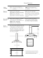
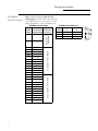
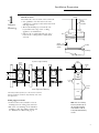
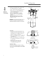
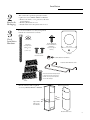
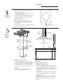
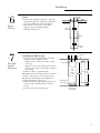
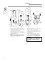
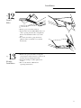
GE Monogram®
Installation
Instructions
36" Island
Vent Hood
Model
ZV850
Before you begin – Read these instructions completely and carefully.
IMPORTANT – Save these instructions for local inspector’s use.
IMPORTANT – OBSERVE ALL GOVERNING CODES AND ORDINANCES.
Note to Installer – Be sure to leave these instructions with the Consumer.
Note to Consumer – Keep these instructions with your Owner’s Manual for future reference.
WARNING: This appliance must be properly grounded. See “Electrical Supply,” page 5.
If you have a question concerning the
installation of this product, call the GE Answer
Center® Consumer Information Service at
800.626.2000, 24 hours a day, 7 days a week.
If you received a damaged vent hood, you
should immediately contact your dealer or
builder.
For Monogram local service in your area,
1.800.444.1845.
For Monogram service in Canada, call
1.888.880.3030.
For Monogram Parts and Accessories, call
1.800.626.2002.
CAUTION!
Due to the weight and size of this vent hood
and to reduce the risk of personal injury or
damage to the product, TWO PEOPLE ARE
REQUIRED FOR PROPER INSTALLATION.
Proper installation is the responsibility of
the installer. Product failure due to improper
installation is not covered under the GE
Appliance Warranty. See the Owner’s
Manual for warranty information.
WARNING:
To reduce the risk of fire or electrical
shock, do not use this hood with any external
solid-state speed control device. Any such
alteration from original factory wiring could
result in damage to the unit and/or create
an electrical safety hazard.
To reduce the risk of fire and to properly
exhaust air, be sure to duct air outdoors. Do
not vent exhaust air into spaces within walls or
ceilings or into attics, crawl spaces or garages.
WARNING: TO REDUCE THE RISK OF FIRE,
USE ONLY METAL DUCTWORK.
Contents
2
Model Available ............................................ 3
Required Accessory ...................................... 3
Recirculating Operation .............................. 3
Product Dimensions ..................................... 3
Using Duct Cover Accessories ..................... 4
Installation Preparation
Tools and Materials Required ..................... 5
Power Supply ................................................ 5
Duct Fittings ................................................. 6
Step 1, Advance Planning ........................ 7, 8
Installation
Step 2, Remove the Packaging .................... 9
TO REDUCE THE RISK OF FIRE,
ELECTRICAL SHOCK OR INJURY TO
PERSONS, OBSERVE THE FOLLOWING:
A. Use this unit only in the manner intended
by the manufacturer. If you have any
questions, contact the manufacturer.
B. Before servicing or cleaning unit, switch
power off at the service panel and lock service
panel to prevent power from being switched
on accidentally. If the service panel cannot be
locked, fasten a tag or prominent warning
label to the panel.
For general ventilating use only. Do not use
to exhaust hazardous or explosive materials
or vapors.
Structural framing, installation work and
electrical wiring must be done by qualified
person(s), in accordance with all applicable
codes and standards including fire-rated
construction.
Sufficient air is needed for proper combustion
and exhausting of gases through the flue
(chimney) of fuel burning equipment to
prevent back drafting. Follow the heating
equipment manufacturer’s guidelines and
safety standards such as those published by
the National Fire Protection Association
(NFPA), and the American Society for
Heating, Refrigeration and Air Conditioning
Engineers (ASHRAE), and the local code
authorities.
Local codes vary. Installation electrical
connections and grounding must comply
with applicable codes. In the absence of
local codes, the vent should be installed in
accordance with National Electrical Code
ANSI/NFPA 70-1990 or latest edition.
Step 3, Check Installation Hardware .......... 9
Step 4, Mount Template ............................ 10
Step 5, Install Support Frame .................... 10
Step 6, Secure Wiring ................................ 11
Step 7, Size and Install Ductwork .............. 11
Step 8, Install Decorative Duct Covers ..... 12
Step 9, Install Hood ................................... 13
Step 10, Connect Electrical ....................... 13
Step 11, Slide Duct Cover Down,
Install Side Utility Bars ................ 14
Step 12, Install Filters ................................. 15
Step 13, Finalize Installation ..................... 15
Design Information
36" Island Vent Hood
This vent hood is designed to
be used in vented ceiling mounted
installations.
Model
Available
Model
ZV850
Required
Accessory
ZX858 – For 8 ft. ceiling height.
This kit includes decorative duct covers and
support frames to reach an 8 ft ceiling height.
ZX859 – For 9 ft. ceiling height.
This kit includes decorative duct covers and
support frames to reach an 9 ft ceiling height.
ZX8510 – For 10 ft. ceiling height.
This kit includes decorative duct covers and
support frames to reach a 10 ft. ceiling height.
Order the required accessory at the same time
as the vent hood and have on site before
installation.
Recirculating
Operation
This hood may be installed for recirculating
operation. One of the following kits is
required and must be ordered with the hood.
ZXR858 – For 8 ft. ceiling height.
ZXR859 – For 9 ft. ceiling height.
ZXR8510 – For 10 ft. ceiling height.
Both the hood and accessory must be
on site at the time of installation. Follow
the installation instructions packed with
the accessory to complete the installation.
Product
Dimensions
The vent hood must be installed 24" min. and
30" max. above the cooking surface. 25-1/2" is
recommended for best venting performance
and to insure that the duct cover meets the
ceiling. The cooking surface should be at least
36" above the floor. Installation will be easier if
the vent hood is installed before the cooktop
and countertop is installed.
NOTE: Accessories to meet proper
ceiling height are required to complete
the installation.
*Height
to Ceiling
8-1/4"
35-3/8"
27-1/2"
*26-1/4" for 8 ft. Ceiling
Using ZX858 Accessory
38-1/8" for 9 ft. Ceiling
Using ZX859 Accessory
*25-1/2" Recommended
36" Reference
50-1/8" for 10 ft. Ceiling
Using ZX8510 Accessory
* The distance between the cooking surface and the bottom
of the hood must be at least 24” and up to 30”. The 25-1/2”
recommended installation height, above the standard 36”
countertop, will insure duct cover fit to the ceiling.
3
Design Information
36" Island Vent Hood
Using Duct
Cover Accessories
A duct cover accessory is required for all
ceiling heights. Use this chart to determine the
correct Duct Cover Accessory for 8 ft. to 10 ft.
ceilings that must be ordered with the hood.
ZV850SB Installation Heights
8′ 0″
25-1/2″
8′ 1″
25-1/2″ to 26-1/2″
8′ 2″
25-1/2″ to 27-1/2″
8′ 3″
25-1/2″ to 28-1/2″
8′ 4″
25-1/2″ to 29-1/2″
8′ 5″
30″ max.
8′ 6″
30″ max.
8′ 7″
30″ max.
8′ 8″
30″ max.
8′ 9″
30″ max.
8′ 10″
30″ max.
8′ 11″
30″ max.
9′ 0″
30″ max.
9′ 1″
30″ max.
9′ 2″
30″ max.
9′ 3″
30″ max.
9′ 4″
30″ max.
9′ 5″
30″ max.
9′ 6″
30″ max.
9′ 7″
30″ max.
9′ 8″
30″ max.
9′ 9″
30″ max.
9′ 10″
30″ max.
9′ 11″
30″ max.
10′ 0″
30″ max.
* Based on 36″ countertop height.
4
ACCE S S O R Y
Z X 858SB
24-1/2″
A CC E S S O R Y Z X 859SB
7′ 11″
Duct Cover
Accessory
A CC E S S O R Y Z X 8510SB
Actual
Ceiling * Possible Hood
Height Installation Height
ZV850 Duct Cover Dimensions
Vented
Installation
A
B
ZX858SB
14-3/16″
15-3/16″
ZX859SB
20-1/2″
22-1/2″
ZX8510SB
26″
27-1/2″
9-7/16"
B
A
15-3/4"
Installation Preparation
36" Island Vent Hood
Tools and
Materials
Required
(not supplied)
Power
Supply
• Tape measure
• Knife
• Spirit level
• Wire cutter
• Wire stripper
• Wire nuts
• Electric drill and 5/32” bit
• Phillips screwdriver
• Flat blade screwdriver
• Hammer
• Pliers
• 10 mm Hex wrench/socket
• Safety glasses
• Tape to mount template
• Gloves to protect against sharp edges
• 120V 60Hz. 15 or 20 Amp, 2 wire with ground.
Properly grounded branch circuit.
• Strain relief for junction box cover.
• Plumb
• Center punch
IMPORTANT - (Please read carefully)
Grounding Instructions
The grounding conductor must be connected
to a ground metal, permanent wiring system,
or an equipment-grounding terminal or lead
on the hood.
CAUTION
WARNING FOR PERSONAL SAFETY, THIS
APPLIANCE MUST BE PROPERLY
GROUNDED.
Remove house fuse or open circuit
breaker before beginning
installation.
Do not use an extension cord or adapter
plug with this appliance. Follow National
Electrical Code or prevailing local codes
and ordinances.
Electrical supply
This vent hood must be supplied with 120V,
60Hz, and connected to an individual,
properly grounded branch circuit, and
protected by a 15 or 20 amp circuit
breaker or time delay fuse.
• Wiring must be 2 wire with ground.
• If the electrical supply does not meet
the above requirements, call a licensed
electrician before proceeding.
• Route house wiring in the ceiling, as
close to the installation location as possible.
Allow an additional 3 feet length from
ceiling joists to reach the junction box
on the hood.
• Connect the wiring to the house wiring in
accordance with local codes.
CAUTION
WARNING
Warning: The improper
connection of the equipmentgrounding conductor can result in
a risk of electric shock. Check with
a qualified electrician or service
representative if you are in doubt whether
the appliance is properly grounded.
5
Installation Preparation
36" Island Vent Hood
Duct
fittings
This Hood Must
Use 6" Round Duct
It Can Transition to
3-1/4" x 10" or
3-1/4" x 12" Duct
Use this chart to
compute maximum
permissable lengths
for duct runs to
outdoors.
Note: Do not exceed
maximum permissable
equivalent lengths!
Maximum duct length:
100 foot for range hoods.
Flexible ducting:
If flexible metal
ducting is used, all
the equivalent feet
values in the table
should be doubled.
The flexible metal
duct should be
straight and smooth
and extended as
much as possible.
Do NOT use flexible
plastic ducting.
Note: Any home ventilation
system, such as a ventilation
hood, may interrupt the proper
flow of combustion air and
exhaust required by fireplaces,
gas furnaces, gas water heaters
and other naturally vented
systems. To minimize the chance
of interruption of such naturally
vented systems, follow the
heating equipment
manufacturer’s guidelines and
safety standards such as those
published by NFPA and ASHRAE.
Duct Piece Dimensions
Round,
straight
1 ft.
(per foot
length)
3-1⁄ 4" x 10"
straight
1 ft.
(per foot
length)
90° elbow
12 ft.
45° elbow
7 ft.
3-1⁄ 4" x 10"
3-1⁄ 4" x 12"
90° elbow
14 ft.
10 ft.
3-1⁄ 4" x 10"
3-1⁄ 4" x 12"
45° elbow
8 ft.
6 ft.
3-1⁄ 4" x 10"
3-1⁄ 4" x 12"
90° flat elbow
33 ft.
24 ft.
6" round to
rectangular
2 ft.
Rectangular
to 6" round
2 ft.
3-1⁄ 4" x 10"
3-1⁄ 4" x 12"
6" round to
rectangular
transition 90° elbow
4 ft.
4 ft.
3-1⁄ 4" x 10"
3-1⁄ 4" x 12"
Rectangular to 6" round
transition 90° elbow
4 ft.
4 ft.
Round
wall cap
with damper
6
Total
Equivalent Quantity Equivalent
Length*
Used
Length
24 ft.
3-1⁄ 4" x 10"
3-1⁄ 4" x 12"
Rectangular wall cap
with damper
24 ft.
18 ft.
Round roof cap
33 ft.
*Actual length of straight duct plus duct fitting
equivalent. Equivalent length of duct pieces are based
on actual tests conducted by GE Evaluation Engineering
and reflect requirements for good venting performance
with any ventilation hood.
Total Duct Run
Installation Preparation
36" Island Vent Hood
1
Step
Advance
Planning
Plan the location
Determine the exact location of the vent hood.
• Use a plumb to check location to be sure
countertop/cooktop location below the hood
will align exactly.
• The hood should project forward 1-1/2"
beyond the front edge of the cooking
appliance. See illustration.
• Observe the recommended 25-1/2" space
between the cooking surface and bottom
of hood.
Ceiling
Hood
Ducting
Centerline
Hood
Front
13-3/4"
27-1/2"
Approx. 1-1/2"
Beyond Cooking
Surface
Cooktop
Countertop
Side View
Cross
Framing
Top View of Support Framing
8-3/4"
Cross
Framing
Ceiling
8-3/4"
*7-5/8"
16"
Joist
Side
View
Front of
Hood
Upper
Support
Frames
Typical Support Frame Mounting
*The framing should be spaced 8-3/4” on the sides and 7-5/8" at the
front from centerline to centerline to accept mounting screws in the
vent support frame.
Ceiling support structure
• At the hood location, install 2 x 4 cross
framing between ceiling joists as shown.
• The 2 x 4 cross framing can be installed
standing or flat, depending on duct run.
See illustration of ductwork, page 8.
Lower
Note: The cross framing
must be spaced 8-3/4” on
the side from centerline
to centerline in order to
accept the hood mounting
screws.
7
Installation Preparation
36" Island Vent Hood
1
Step
Advance
Planning
(continued)
• Arrange cross framing in the ceiling to suit
the existing structure. See examples.
– Secure each 2 x 4 block with at least four (4),
#10 wood screws, 3" long (minimum size
screws, not supplied). Use 8 wood screws
total for the two supports.
• The cross framing must be accurately
aligned to assure correct positioning of
the hood.
• The cross framing must be level in all
directions. Check with a spirit level and
adjust if necessary.
IMPORTANT: The ceiling structure must be capable of supporting
the weight of the hood (approximately 100 pounds) and any
inadvertent user contact loads. It is recommended that the hood
support frame be supported by a minimum of 2 x 4 cross framing.
Ductwork
• Use the shortest and straightest duct route
possible. For satisfactory performance, duct
run should not exceed 100 feet equivalent
length for any duct configuration.
• Refer to “Duct Fittings” chart to compute the
maximum permissible length for duct runs
to the outdoors.
• This vent hood must use 6" round duct. The
6" round duct can transition to 3-1/4" x 10"
or 3-1/4" x 12".
• Install the house ductwork to run
horizontally between ceiling joists
or straight up through the roof.
Finish the Ceiling
Finish the ceiling surface. Be sure to mark
location of the ceiling joists and cross framing.
Check to be sure that ceiling is level, use shims
if necessary.
8
Cross Framing
8-3/4"
Ceiling
Joist
7-5/8"
Upper Half
Of Support
Frame
Support
Frame
Opening
Front
of
Hood
Height
Adjustment
Slot
Ceiling Joint
6"
Duct
2x4
Vent Straight Up
Through The Ceiling
6" Round
Duct Elbow
Flat
Standing
Vent Between
Ceiling Joists
Installation
36" Island Vent Hood
2
The vent hood is packed separately from the
required accessory ZX858, ZX859 or ZX8510.
• Remove the frame, cover, parts box, side bars
and packaging.
• Remove junction box cover.
• Install strain relief onto junction box cover.
3
Locate the hardware accessory box packed
with the hood and check contents.
Step
Remove the
Packaging
S tep
Check
Installation
Hardware
4 Flat Washers
8 Frame Attachment
Screws with Washers
(attached to
accessory support
frames)
4 Hex head
wood lag screws
(6mm x 2-1/2")
or
(1/4 x 2-1/2")
Front of Hood
Template
2 Phillips Head
Decorative Screws
4 (10mm) Nuts and Lock Washers
2 Side Bars With 4 Machine Screws
Check service manual envelope taped
to the front of the hood to be sure it
contains one stop screw. Leave this
screw in the envelope.
3 Filters
Check contents of the required
accessory, ZX858, ZX859 or ZX8510.
Mounting Screw Holes
Support Frames
with 8 Screws
and 8 Washers
Decorative Duct Covers
9
Installation
36" Island Vent Hood
4
Step
Mount
Template
• Align the template with the marks on the
ceiling and tape in place.
– Be sure the template is oriented correctly,
with the front of the hood.
• Use a plumb to be sure the mounting holes
will provide parallel alignment with the
countertop below.
• Center punch all hole locations.
• Drill pilot holes in the 4 screw locations.
Use a 5/32" bit and drill approximately
1-1/2" deep.
• Cut the 6-1/4" dia. duct opening and approx.
1" dia. wire access hole.
5
Step
Wire Access Hole
Hood
Mounting
Flange
Install
Support
Frame
Lower Support
13-5/8
Upper
Support
Frame
Lower
Support
Frame
10
Front of Hood
Front
Of
Hood
Support
Frame
Opening
Check Level in
Both Direction
*39-1/8"
25-1/2" Recommended
**75-1/8"
to Floor
Countertop
Install upper support frame
*Note: 39-1/8" to top of hood flange can be increased
• Secure the upper support frame to the
up to 42" max.
ceiling joists and/or cross framing with the **75-1/8" min. to floor, 77-7/8" max.
4 screws provided. For maximum rigidity
Install lower support frame
and strength, the screws must be driven
• Insert lower support frame (from required
into the center of the joists and/or cross
accessory ZX858, ZX859 or ZX8510) into the
framing.
upper support frame and loosely secure with
• Check to be sure the support frame is
8 screws and washers (4 on front and 4 on
level, vertically and horizontally.
back sides).
• Adjust the lower support frame up or down
to the desired height above the countertop.
Tighten screws.
Important: Again, check to be sure the support
is level in both directions. There is no way to
level the hood after the hood is secured to
the frame.
Installation
36" Island Vent Hood
6
Step
Secure
Wiring
Wiring
• Route house wiring through the ceiling hole
and pull a length to reach the hood junction
box, approximately 6" below the support.
• Tape the wire to the front of the frame
support to prevent damage during
installation and service.
Ceiling
Front Side
Support
Frames
Tape
House
Wiring
7
Step
Size And
Install
Ductwork
To Find Required Duct Length:
• Measure from house duct flange to bottom
of support frame. (Dimension A)
– Add at least 1" to Dim. A for duct overlap
at the top.
– Subtract 1-3/4" for hood insertion into the
bottom of the frame to determine required
duct length.
• Cut the 6" duct to required length.
Note: The bottom of the duct must be external
(female) connection to the top of the hood.
The bottom end should be flared slightly, to
facilitate installation of the hood.
• Install duct up through support frames and
attach to house ducting with sheet metal
screws.
• Seal the connection with duct tape.
Ceiling
House Duct
Side
View
Support
Frame
Duct
Dim. A
Required
Duct
Length
Duct Connection
To Hood
1-3/4"
Bottom Support
Frame Flange
11
Installation
36" Island Vent Hood
8
Step
Install
Decorative
Duct Covers
Install Screw on
Each Side
Pretap
2 Screw
Holes
Top Duct
Cover
Bottom Duct Cover
Top Duct
Cover
Bottom Duct
Cover
Top Duct
Cover
Stop Screw
Install Stop
Screw in One
of 3 Holes
• Pretap or drive decorative screw into the
screw holes on the support frame. This will
make screw installation easier.
• Separate the two decorative duct covers.
• Select the inside (top) cover, which has two
screw holes in the top.
• Slide the decorative duct cover over the
support frame and push to the ceiling.
• Attach to the hood support at the top with
2 supplied decorative screws.
12
• Locate the stop screw in the envelope taped
to the front of the hood. Set aside.
• Slide the bottom decorative duct over the
installed top duct and push up past the stop
screw hole location.
• Install the supplied temporary stop screw
in one of 3 holes in the support frame or
the top duct cover to prevent the bottom
decorative duct cover from sliding down.
The stop screw must be
installed. Failure to do so could result in
personal injury or damage to the duct
cover.
Installation
36" Island Vent Hood
9
Step
Align Duct
Connector to
House Duct
Install
Hood
Align
Mounting
Studs
Note: TWO PEOPLE ARE REQUIRED TO
COMPLETE THIS INSTALLATION!
• Lift the hood up to the support frame.
Carefully align the hood mounting studs
into the support frame holes, and at the
same time, guide the hood duct connector
into the house duct.
• Install 4 nuts and lock washers to the
mounting studs. Tighten with a 10mm
wrench.
10
Step
Connect
Electrical
Verify that power is turned off at the source.
WARNING
CAUTION
If house wiring is not 2-wire with
a ground wire, a ground must be
provided by the installer.
When house wiring is aluminum,
be sure to use U.L. approved
anti-oxidant compound and
aluminum-to-copper connectors.
Bottom
Duct
Cover
Stop Screw
Install
4 lock
washer
and 4 Nuts
• Check hood level in both directions.
• Check to be sure that the duct is positioned
over the hood connector.
• Seal the duct connection with duct tape.
Note: Do not drive screws through lower duct
connection. Doing so will prevent proper
damper operation.
• Install strain relief into the knockout of the
junction box cover.
• Insert house wiring through strain relief and
tighten.
• Connect white leads to branch circuit white
lead.
• Connect black leads to branch circuit black
lead.
• Connect green/yellow leads to branch
circuit green or bare ground lead.
• Secure all connections with wire nuts on
each electrical connector.
• Push wires into junction box and replace
cover. Be sure wires are not pinched.
13
Installation
36" Island Vent Hood
Step
11
Slide Duct
Cover Down,
Install Side
Utility Bars
• Hold the decorative duct cover and
remove the temporary stop screw. Return
the screw to the service manual envelope
for future use.
• Slide the lower duct cover down onto
the hood.
14
• Install the side utility bars with screws
as shown.
Installation
36" Island Vent Hood
12
Step
Install
Filters
Lower Filter
Slots
• Remove protective film on filters.
• Tip the filter into the lower slots at the rear
of the opening. Lift the filter and pull the
knob forward until the filter rests on the
slots.
• To remove the filters, grasp the knob,
push the filter towards the rear and tilt
downwards.
Step
13
Finalize
Installation
• Remove the protective film covering the
control panel on the front face of the hood,
and any other packaging materials.
• Check all 4 lamps to assure tightness in
sockets.
• Refer to the Owner’s Manual for
operating instructions.
15
NOTE: While performing installations described in this
book, safety glasses or goggles should be worn.
For Monogram local service in your area, call
1.800.444.1845.
GE Consumer & Industrial
GE Appliances
General Electric Company
Louisville, KY 40225
NOTE: Product improvement is a continuing endeavor at General Electric.
Therefore, materials, appearance and specifications are subject to change
without notice.
Pub. No. 49-8970-2
04/07 JR
Printed in Italy
monogram.com
©2007 GE Company
04306398