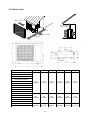
1
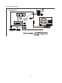
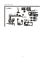
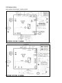
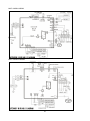
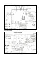
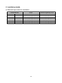
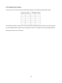
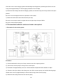
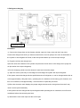
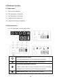
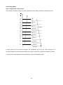
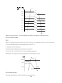
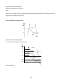
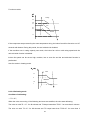
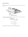
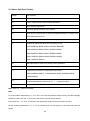
9ASUL-A1-1211 SERVICE MANUAL MIDEA AIRCONDITIONER DC INVERTER SPLIT WALL-MOUNTED TYPE CONTENTS 1. Precaution .................................................................................................................................................... 1 1.1 Safety Precaution .......................................................................................................................... 1 1.2 Warning ......................................................................................................................................... 1 2. Function ........................................................................................................................................................ 6 3. Dimension .................................................................................................................................................... 8 3.1 Indoor Units ................................................................................................................................... 8 3.2 Outdoor Units ...............................................................................................................................11 4. Refrigerant Cycle Diagram ....................................................................................................................... 12 5. Wiring Diagram .......................................................................................................................................... 14 5.1 Indoor Units ................................................................................................................................. 14 5.2 Outdoor Units .............................................................................................................................. 19 6. Installation details ..................................................................................................................................... 25 6.1 Wrench torque sheet for installation ........................................................................................... 25 6.2 Connecting the cables ................................................................................................................ 26 6.3 Pipe length and the elevation ..................................................................................................... 27 6.4 Installation for the first time ......................................................................................................... 28 6.5 Adding the refrigerant after running the system for many years ................................................ 31 6.6 Re-installation while the indoor unit need to be repaired ........................................................... 32 6.7 Re-installation while the outdoor unit need to be repaired ......................................................... 34 7. Operation characteristics ......................................................................................................................... 37 8. Electronic function .................................................................................................................................... 38 8.1 Abbreviation ................................................................................................................................ 38 8.2 Display function ........................................................................................................................... 38 8.3 Main Protection ........................................................................................................................... 39 8.4 Operation Modes and Functions................................................................................................. 40 9. Troubleshooting ......................................................................................................................................... 54 9.1 Indoor Unit Error Display............................................................................................................. 55 9.2 Outdoor unit error display ........................................................................................................... 57 9.3 Diagnosis and Solution ............................................................................................................... 59 1. Precaution 1.1 Safety Precaution To prevent injury to the user or other people and property damage, the following instructions must be followed. Incorrect operation due to ignoring instruction will cause harm or damage. Before service unit, be sure to read this service manual at first. 1.2 Warning Installation Do not use a defective or underrated circuit breaker. Use this appliance on a dedicated circuit. There is risk of fire or electric shock. For electrical work, contact the dealer, seller, a qualified electrician, or an Authorized service center. Do not disassemble or repair the product, there is risk of fire or electric shock. Always ground the product. There is risk of fire or electric shock. Install the panel and the cover of control box securely. There is risk of fire of electric shock. Always install a dedicated circuit and breaker. Improper wiring or installation may cause fore or electric shock. Use the correctly rated breaker of fuse. There is risk of fire or electric shock. Do not modify or extend the power cable. There is risk of fire or electric shock. Do not install, remove, or reinstall the unit by yourself(customer). There is risk of fire, electric shock, explosion, or injury. Be caution when unpacking and installing the product. Sharp edges could cause injury, be especially careful of the case edges and the fins on the 1 condenser and evaporator. For installation, always contact the dealer or an Authorized service center. There is risk of fire, electric shock, explosion, or injury. Do not install the product on a defective installation stand. It may cause injury, accident, or damage to the product. Be sure the installation area does not deteriorate with age. If the base collapses, the air conditioner could fall with it, causing property damage, product failure, and personal injury. Do not let the air conditioner run for a long time when the humidity is very high and a door or a window is left open. Moisture may condense and wet or damage furniture. Take care to ensure that power cable could not be pulled out or damaged during operation. There is risk of fire or electric shock. Do not place anything on the power cable. There is risk of fire or electric shock. Do not plug or unplug the power supply plug during operation. There is risk of fire or electric shock. Do not touch (operation) the product with wet hands. There is risk of fire or electric shock. Do not place a heater or other appliance near the power cable. There is risk of fire and electric shock. Do not allow water to run into electric parts. It may cause fire, failure of the product, or electric shock. Do not store or use flammable gas or combustible near the product. There is risk of fire or failure of product. Do not use the product in a tightly closed space for a long time. Oxygen deficiency could occur. When flammable gas leaks, turn off the gas and open a window for ventilation before turn the product on. Do not use the telephone or turn switches on or off. 2 There is risk of explosion or fire. If strange sounds, or small or smoke comes from product. Turn the breaker off or disconnect the power supply cable. There is risk of electric shock or fire. Stop operation and close the window in storm or hurricane. If possible, remove the product from the window before the hurricane arrives. There is risk of property damage, failure of product, or electric shock. Do not open the inlet grill of the product during operation. (Do not touch the electrostatic filter, if the unit is so equipped.) There is risk of physical injury, electric shock, or product failure. When the product is soaked (flooded or submerged), contact an Authorized service center. There is risk of fire or electric shock. Be caution that water could not enter the product. There is risk of fire, electric shock, or product damage. Ventilate the product from time to time when operating it together with a stove, etc. There is risk of fire or electric shock. Turn the main power off when cleaning or maintaining the product. There is risk of electric shock. When the product is not be used for a long time, disconnect the power supply plug or turn off the breaker. There is risk of product damage or failure, or unintended operation. Take care to ensure that nobody could step on or fall onto the outdoor unit. This could result in personal injury and product damage. CAUTION Always check for gas (refrigerant) leakage after installation or repair of product. Low refrigerant levels may cause failure of product. Install the drain hose to ensure that water is drained away properly. A bad connection may cause water leakage. 3 Keep level even when installing the product. It can avoid vibration of water leakage. Do not install the product where the noise or hot air from the outdoor unit could damage the neighborhoods. It may cause a problem for your neighbors. Use two or more people to lift and transport the product. Avoid personal injury. Do not install the product where it will be exposed to sea wind (salt spray) directly. It may cause corrosion on the product. Corrosion, particularly on the condenser and evaporator fins, could cause product malfunction or inefficient operation. Operational Do not expose the skin directly to cool air for long periods of time. (Do not sit in the draft). This could harm to your health. Do not use the product for special purposes, such as preserving foods, works of art, etc. It is a consumer air conditioner, not a precision refrigerant system. There is risk of damage or loss of property. Do not block the inlet or outlet of air flow. It may cause product failure. Use a soft cloth to clean. Do not use harsh detergents, solvents, etc. There is risk of fire, electric shock, or damage to the plastic parts of the product. Do not touch the metal parts of the product when removing the air filter. They are very sharp. There is risk of personal injury. Do not step on or put anything on the product. (outdoor units) There is risk of personal injury and failure of product. Always insert the filter securely. Clean the filter every two weeks or more often if necessary. A dirty filter reduces the efficiency of the air conditioner and could cause product malfunction or 4 damage. Do not insert hands or other object through air inlet or outlet while the product is operated. There are sharp and moving parts that could cause personal injury. Do not drink the water drained from the product. It is not sanitary could cause serious health issues. Use a firm stool or ladder when cleaning or maintaining the product. Be careful and avoid personal injury. Replace the all batteries in the remote control with new ones of the same type. Do not mix old and mew batteries or different types of batteries. There is risk of fire or explosion. Do not recharge or disassemble the batteries. Do not dispose of batteries in a fire. They may burn of explode. If the liquid from the batteries gets onto your skin or clothes, wash it well with clean water. Do not use the remote of the batteries have leaked. The chemical in batteries could cause burns or other health hazards 5 2. Function Model Names of Indoor/Outdoor Units Capacity Model Indoor units Outdoor units MS9A-09HRDN1-MP0W MS9A-09HRDN1-MP0W MOC-09HDN1-MP0W MS9A-09CRDN1-BS0W MS9A-09CRDN1-BS0W MOC-09CFN1-BS0W MS9A-09HRDN1-BS0W MS9A-09HRDN1-BS0W MOC-09HRFN1-BS0W MS9A-09HRDN1-BQ0W MS9A-09HRDN1-BQ0W MOC-09HFN1-BQ0W MS9A-12HRDN1-MP0W MS9A-12HRDN1-MP0W MOC-12HDN1-MP0W MS9A-12CRDN1-BS0W MS9A-12CRDN1-BS0W MOC-12CFN1-BS0W MS9A-12CRDN1-MS0W MS9A-12CRDN1-MS0W MOC-12CRDN1-MS0W MS9A-12HRDN1-BS0W MS9A-12HRDN1-BS0W MOC-12HRFN1-BS0W MS9A-12HRDN1-MS0W MS9A-12HRDN1-MS0W MOC-12HRFN1-MS0W MS9A-12HRDN1-BS0W(B) MS9A-12HRDN1-BS0W(B) MOC-12HFN1-BS0W MS9A-18HRDN1-MP0W MS9A-18HRDN1-MP0W MOF-18HDN1-MP0W MS9A-18CRDN1-MS0W MS9A-18CRDN1-MS0W MOF-18CRFN1-MS0W MS9A-18HRDN1-MS0W MS9A-18HRDN1-MS0W MOF-18HRFN1-MS0W MS9A-24HRDN1-MP0W MS9A-24HRDN1-MP0W MOG-24HDN1-MP0W MS9A-24HRDN1-MP0W MS9A-24HRDN1-MP0W MOF-24HDN1-MP0W MS9A-24HRDN1-MS0W MS9A-24HRDN1-MS0W MOG-24HDN1-MS0W MS9A-24CRDN1-MP0W MOF-24CDN1-MP0W MOF-24CDN1-MP0W 9K 12K DC Inverter 18K 24K 6 Filter killer of formaldehyde Ionizer+(O) Ionizer(O) Plasma(O) Heat compensation(O) Silver Ico Filter(O) Self-diag. function Vitamin C Filter(O) Hydrophilic aluminum fin 3M HAM Filter(O) Anti-rust cabinet Bio Filter(O) Valve protection cover Golden Fin(O) PTC Heating Belt(O) 8 degree heating(O) Compressor Crankcase Heater(O) O: optional function 7 3. Dimension 3.1 Indoor Units Model W(mm) H(mm) D(mm) MS9A-09HRDN1-MP0W MS9A-09HRDN1-BQ0W 790 (31.10in) 265 (10.43in) 198 (7.80in) MS9A-09CRDN1-BS0W MS9A-09HRDN1-BS0W MS9A-12HRDN1-MP0W MS9A-12CRDN1-BS0W MS9A-12HRDN1-BS0W MS9A-12CRDN1-MS0W MS9A-12HRDN1-MS0W MS9A-12HRDN1-BS0W(B) 920 (36.22in) 292 (11.50in) 223 (8.78in) MS9A-18HRDN1-MP0W MS9A-18CRDN1-MS0W MS9A-18HRDN1-MS0W MS9A-24HRDN1-MP0W MS9A-24CRDN1-MP0W 998 (39.29in) 322 (12.68in) 240 (9.45in) MS9A-24HRDN1-MS0W 1450 (57.09in) 340 (13.39in) 265 (10.43in) 8 L R H Model L(mm) R(mm) H(mm) Dimension of installation hole(mm) MS9A-09HRDN1-MP0W MS9A-09HRDN1-BQ0W 100 151 45 Φ65 R L H Model L(mm) R(mm) H(mm) Dimension of installation hole(mm) 150 187 45 Φ65 MS9A-09CRDN1-BS0W MS9A-09HRDN1-BS0W MS9A-12HRDN1-MP0W MS9A-12CRDN1-BS0W MS9A-12HRDN1-BS0W 9 MS9A-12CRDN1-MS0W MS9A-12HRDN1-MS0W MS9A-12HRDN1-BS0W(B) Model L(mm) R(mm) H(mm) Dimension of installation hole(mm) 100 119 45 Φ65 MS9A-18HRDN1-MP0W MS9A-18CRDN1-MS0W MS9A-18HRDN1-MS0W MS9A-24HRDN1-MP0W MS9A-24CRDN1-MP0W Model L(mm) H(mm) Dimension of installation hole(mm) MS9A-24HRDN1-MS0W 120.5 55 Φ95 10 3.2 Outdoor Units More than 30cm More than 60cm (Service space) More than 30cm Fe n ob ce o sta r cle s More than 60cm More than 70cm Model W(mm) D(mm) H(mm) W1(mm) A(mm) B(mm) 760 (29.92in) 285 (11.22in) 590 (23.23in) 823 (32.40in) 530 (20.87in) 290 (11.42in) 845 (33.27in) 320 (12.60in) 700 (27.56in) 908 (35.75in) 560 (22.05in) 335 (13.19in) 900 (35.43in) 315 (12.40in) 860 (33.86in) 980 (38.58in) 590 (23.23in) 333 (13.11in) MOC-09HDN1-MP0W MOC-09CFN1-BS0W MOC-09HRFN1-BS0W MOC-09HFN1-BQ0W MOC-12HDN1-MP0W MOC-12CFN1-BS0W MOC-12CRDN1-MS0W MOC-12HRFN1-BS0W MOC-12HRFN1-MS0W MOC-12HFN1-BS0W MOF-18HDN1-MP0W MOF-18CRFN1-MS0W MOF-18HRFN1-MS0W MOF-24HDN1-MP0W MOF-24CDN1-MP0W MOG-24HDN1-MP0W MOG-24HDN1-MS0W 11 4. Refrigerant Cycle Diagram For cooling only models: INDOOR OUTDOOR LIQUID SIDE CAPILIARY TUBE HEAT EXCHANGE (EVAPORATOR) HEAT EXCHANGE (CONDENSER) GAS SIDE COMPRESSOR 12 For heat pump models: INDOOR OUTDOOR CHECK VALVE (Heating Model only) LIQUID SIDE 2-WAY VALVE CAPILIARY TUBE HEAT EXCHANGE (EVAPORATOR) HEAT EXCHANGE (CONDENSER) GAS SIDE REVERSING VALVE (Heating Model only) 3-WAY VALVE ACCUMULATOR COOLING COMPRESSOR 13 HEATING 5. Wiring Diagram 5.1 Indoor Units MS9A-09HRDN1-MP0W; MS9A-12HRDN1-MP0W; MS9A-12CRDN1-MS0W; MS9A-12HRDN1-MS0W MS9A-09CRDN1-BS0W; MS9A-09HRDN1-BS0W; MS9A-12CRDN1-BS0W; MS9A-12HRDN1-BS0W 14 MS9A-18HRDN1-MP0W;MS9A-18CRDN1-MS0W;MS9A-18HRDN1-MS0W; MS9A-24HRDN1-MP0W 15 MS9A-09HRDN1-BQ0W MS9A-12HRDN1-BS0W(B) 16 MS9A-24CRDN1-MP0W 17 MS9A-24HRDN1-MS0W 18 5.2 Outdoor Units MOC-09HDN1-MP0W;MOC-12HDN1-MP0W MOC-09CFN1-BS0W; MOC-09HRFN1-BS0W; MOC-12CFN1-BS0W; MOC-12HRFN1-BS0W 19 MOC-12CRDN1-MS0W MOC-12HRFN1-MS0W 20 MOF-18HDN1-MP0W MOF-18CRFN1-MS0W 21 MOF-18HRFN1-MS0W MOG-24HDN1-MP0W 22 MOC-09HFN1-BQ0W, MOC-12HFN1-BS0W MOF-24HDN1-MP0W 23 MOG-24HDN1-MS0W MOF-24CDN1-MP0W 24 6. Installation details 6.1 Wrench torque sheet for installation Outside diameter Torque Additional tightening torque mm inch N.cm N.cm Ф6.35 1/4 1500(153kgf.cm) 1600(163kgf.cm) Ф9.52 3/8 2500(255kgf.cm) 2600(265kgf.cm) Ф12.7 1/2 3500(357kgf.cm) 3600(367kgf.cm) Ф15.9 5/8 4500(459kgf.cm) 4700(479kgf.cm) Ф19 3/4 6500(663kgf.cm) 6700(683kgf.cm) 25 6.2 Connecting the cables The power cord of connect should be selected according to the following specifications sheet. The cable size and the current of the fuse or switch are determined by the maximum current indicated on the nameplate which located on the side panel of the unit. Please refer to the nameplate before selecting the cable, fuse and switch. 26 6.3 Pipe length and the elevation The pipe length and refrigerant amount: Model Connective pipe Air purging method Additional amount of refrigerant to be charged length All Less than 5m Use vacuum pump ------------------ 9k/12k More than 5m Use vacuum pump (Pipe length – 5) × 20g/m 18k/24k More than 5m Use vacuum pump (Pipe length – 5) × 40g/m Standard Max. Max. length Elevation Length (m) B (m) A (m) 9k/12k 5 8 20 18k/24k 5 10 25 Model Caution: The capacity test is based on the standard length and the maximum permissive length is based on the system reliability. The oil trap should be installed per 5-7 meters. 27 6.4 Installation for the first time Air and moisture in the refrigerant system have undesirable effects as below: ● ● ● ● ● Pressure in the system rises. Operating current rises. Cooling or heating efficiency drops. Moisture in the refrigerant circuit may freeze and block capillary tubing. Water may lead to corrosion of parts in the refrigerant system. Therefore, the indoor units and the pipes between indoor and outdoor units must be leak tested and evacuated to remove gas and moisture from the system. Gas leak check (Soap water method): Apply soap water or a liquid neutral detergent on the indoor unit connections or outdoor unit connections by a soft brush to check for leakage of the connecting points of the piping. If bubbles come out, the pipes have leakage. 1. Air purging with vacuum pump (Indoor unit) (Outdoor unit) (Liquid side) Two-way valve Close (Gas side) Three-way valve Manifold valve Compound meter Pressure gauge -0.1MPa Lo Handle Lo Charge hose Close Hi Handle Hi Charge hose Vacuum pump Vacuum pump 1) Completely tighten the flare nuts of the indoor and outdoor units, confirm that both the 2-way and 3-way valves are set to the closed position. 2) Connect the charge hose with the push pin of handle lo to the 3-way valves gas service port.. 3) Connect the charge hose of handle hi connection to the vacuum pump. 4) Fully open the handle Lo of the manifold valve. 5) Operate the vacuum pump to evacuate. 6) Make evacuation for 30 minutes and check whether the compound meter indicates -0.1Mpa. If 28 the meter does not indicate -0.1Mpa after pumping 30 minutes, it should be pumped 20 minutes more. If the pressure can’t achieve -0.1Mpa after pumping 50 minutes, please check if there are some leakage points. Fully close the handle Lo valve of the manifold valve and stop the operation of the vacuum pump. Confirm that the gauge needle does not move (approximately 5 minutes after turning off the vacuum pump). 7) Turn the flare nut of the 3-way valves about 45° counterclockwise for 6 or 7seconds after the gas coming out, then tighten the flare nut again. Make sure the pressure display in the pressure indicator is a little higher than the atmosphere pressure. Then remove the charge hose from the 3 way valve. 8) Fully open the 2 way valve and 3 way valve and securely tighten the cap of the 3 way valve. 2. Air purging by refrigerant Procedure: 1). Confirm that both the 2-way and 3-way valves are set to the closed position. 2). Connect the charge set and a charging cylinder to the service port of the 3-way valve. 3). Air purging. Open the valves on the charging cylinder and the charge set. Purge the air by loosening the flare nut on the 2-way valve approximately 45’ for 3 seconds then closing it for 1 minute; repeat 3 times. After purging the air, use a torque wrench to tighten the flare nut on the 2-way valve. 4). Check the gas leakage. Check the flare connections for gas leakage. 5). Discharge the refrigerant. 29 Close the valve on the charging cylinder and discharge the refrigerant by loosening the flare nut on the 2-way valve approximately 45’ until the gauge indicates 0.3 to 0.5 Mpa. 6). Disconnect the charge set and the charging cylinder, and set the 2-way and 3-way valves to the open position. Be sure to use a hexagonal wrench to operate the valve stems. 7). Mount the valve stems nuts and the service port cap. Be sure to use a torque wrench to tighten the service port cap to a torque 18N·m. Be sure to check the gas leakage. 3. Adding the refrigerant if the pipe length >5m Electronic scale Procedure: 1). Connect the charge hose to the charging cylinder, open the 2-way valve and the 3-way valve. Connect the charge hose which you disconnected from the vacuum pump to the valve at the bottom of the cylinder. If the refrigerant is R410A, make the cylinder bottom up to ensure the liquid charge. 2). Purge the air from the charge hose. Open the valve at the bottom of the cylinder and press the check valve on the charge set to purge the air (be careful of the liquid refrigerant). 3) Put the charging cylinder onto the electronic scale and record the weight. 4) Operate the air conditioner at the cooling mode. 5) Open the valves (Low side) on the charge set and charge the system with liquid refrigerant. 30 6).When the electronic scale displays the proper weight (refer to the table), disconnect the charge hose from the 3-way valve’s service port immediately and turn off the air conditioner before disconnecting the hose. 7). Mount the valve stem caps and the service port Use torque wrench to tighten the service port cap to a torque of 18N.m. Be sure to check for gas leakage. 6.5 Adding the refrigerant after running the system for many years Electronic scale Procedure: 1). Connect the charge hose to the 3-way service port, open the 2-way valve and the 3-way valve. Connect the charge hose to the valve at the bottom of the cylinder. If the refrigerant is R410A, make the cylinder bottom up to ensure liquid charge. 2). Purge the air from the charge hose. Open the valve at the bottom of the cylinder and press the check valve on the charge set to purge the air (be careful of the liquid refrigerant). 3) Put the charging cylinder onto the electronic scale and record the weight. 4) Operate the air conditioner at the cooling mode. 5) Open the valves (Low side) on the charge set and charge the system with liquid refrigerant. 31 6).When the electronic scale displays the proper weight (refer to the gauge and the pressure of the low side), disconnect the charge hose from the 3-way valve’s service port immediately and turn off the air conditioner before disconnecting the hose. 7). Mount the valve stem caps and the service port Use torque wrench to tighten the service port cap to a torque of 18N.m. Be sure to check for gas leakage. 6.6 Re-installation while the indoor unit need to be repaired 1. Collecting the refrigerant into the outdoor unit Procedure 1). Confirm that both the 2-way and 3-way valves are set to the opened position Remove the valve stem caps and confirm that the valve stems are in the opened position. Be sure to use a hexagonal wrench to operate the valve stems. 2). Connect the charge hose with the push pin of handle lo to the 3-way valves gas service port. 3). Air purging of the charge hose. Open the handle Lo valve of the manifold valve slightly to purge air from the charge hose for 5 seconds and then close it quickly. 4). Set the 2-way valve to the close position. 32 5). Operate the air conditioner at the cooling cycle and stop it when the gauge indicates 0.1MPa. 6). Set the 3-way valve to the closed position immediately Do this quickly so that the gauge ends up indicating 0.3 to 0.5Mpa. Disconnect the charge set, and tighten the 2-way and 3-way valve’s stem nuts. Use a torque wrench to tighten the 3-way valves service port cap to a torque of 18N.m. Be sure to check for gas leakage. 2. Air purging by the refrigerant Procedure: 1). Confirm that both the 2-way and 3-way valves are set to the closed position. 2). Connect the charge set and a charging cylinder to the service port of the 3-way valve Leave the valve on the charging cylinder closed. 3). Air purging. Open the valves on the charging cylinder and the charge set. Purge the air by loosening the flare nut on the 2-way valve approximately 45’ for 3 seconds then closing it for 1 minute; repeat 3 times. After purging the air, use a torque wrench to tighten the flare nut on the 2-way valve. 4). Check the gas leakage Check the flare connections for gas leakage. 5). Discharge the refrigerant. 33 Close the valve on the charging cylinder and discharge the refrigerant by loosening the flare nut on the 2-way valve approximately 45’ until the gauge indicates 0.3 to 0.5 Mpa. 6). Disconnect the charge set and the charging cylinder, and set the 2-way and 3-way valves to the open position Be sure to use a hexagonal wrench to operate the valve stems. 7). Mount the valve stems nuts and the service port cap Be sure to use a torque wrench to tighten the service port cap to a torque 18N.m. Be sure to check the gas leakage. 6.7 Re-installation while the outdoor unit need to be repaired 1. Evacuation for the whole system Procedure: 1). Confirm that both the 2-way and 3-way valves are set to the opened position. 2). Connect the vacuum pump to 3-way valve’s service port. 3). Evacuation for approximately one hour. Confirm that the compound meter indicates -0.1Mpa. 4). Close the valve (Low side) on the charge set, turn off the vacuum pump, and confirm that the gauge needle does not move (approximately 5 minutes after turning off the vacuum pump). 5). Disconnect the charge hose from the vacuum pump. 34 2. Refrigerant charging Electronic scale Procedure: 1). Connect the charge hose to the charging cylinder, open the 2-way valve and the 3-way valve Connect the charge hose which you disconnected from the vacuum pump to the valve at the bottom of the cylinder. If the refrigerant is R410A, make the cylinder bottom up to ensure liquid charge. 2). Purge the air from the charge hose Open the valve at the bottom of the cylinder and press the check valve on the charge set to purge the air (be careful of the liquid refrigerant). 3) Put the charging cylinder onto the electronic scale and record the weight. 4). Open the valves (Low side) on the charge set and charge the system with liquid refrigerant If the system cannot be charge with the specified amount of refrigerant, or can be charged with a little at a time (approximately 150g each time) , operating the air conditioner in the cooling cycle; however, one time is not sufficient, wait approximately 1 minute and then repeat the procedure. 5).When the electronic scale displays the proper weight, disconnect the charge hose from the 3-way valve’s service port immediately If the system has been charged with liquid refrigerant while operating the air conditioner, turn off the air conditioner before disconnecting the hose. 6). Mounted the valve stem caps and the service port 35 Use torque wrench to tighten the service port cap to a torque of 18N.m. Be sure to check for gas leakage. 36 7. Operation characteristics Temperature Mode Room temperature Cooling operation Heating operation Drying operation ≥17℃(62℉) ≤30℃(86℉) >10℃(50℉) -15℃~30℃ 0℃~50℃ (5℉~86℉) (32℉~122℉) 0℃~50℃ (32℉~122℉) Outdoor temperature -15℃~50℃(5℉~122℉) (For the models with low temperature cooling system) CAUTION: 1. If air conditioner is used outside of the above conditions, certain safety protection features may come into operation and cause the unit to function abnormally. 2. Room relative humidity less than 80%. If the air conditioner operates in excess of this figure, the surface of the air conditioner may attract condensation. Please sets the vertical air flow louver to its maximum angle (vertically to the floor), and set HIGH fan mode. 3. Optimum performance will be achieved within this operating temperature. 37 8. Electronic function 8.1 Abbreviation T1: Indoor room temperature T2: Coil temperature of evaporator T3: Coil temperature of condenser T4: Outdoor ambient temperature T5: Compressor discharge temperature 8.2 Display function 8.2.1 Icon explanation on indoor display board. OPERATION indication lamp: This lamp illuminates when the air conditioner is in operation. AUTO indication lamp: Lights up during the Auto operation. Ion indication lamp(optional function): Lights up when Clean Air feature is activated and Ionizer can generate abundant anions to fill the room with refreshing and natural air. TIMER indication lamp: Lights up during Timer operation. 38 DEFROST indication lamp (For cooling & heating models only): Lights up when the air conditioner starts defrosting automatically or when the warm air control feature is activated in heating operation. DIGITAL DISPLAY: Displays the current setting temperature and malfunction/protection code when the air conditioner is in operation. Frequency display: This display is separated into five zones. The zones illuminate based on the compressor current frequency. For example, higher frequency will illuminate more zones. 8.3 Main Protection 8.3.1 Three Minutes Delay at restart for compressor 1 minute delay for the 1st time start-up and 3 minutes delay for others. 8.3.2 Temperature protection of compressor top The unit will stop working when the compressor top temp. protector cut off, and will restart after the compressor top temp. protector restart. 8.3.3 Temperature protection of compressor discharge When the compressor discharge temp. is getting higher, the running frequency will be limited as below rules: ---Compressor discharge temp. T5>115℃ for 5s, compressor stops. ---108<T5<115℃, decrease the frequency to the lower level every 3 minutes. ---90<T5<105℃, keep running at the current frequency. ----T5<90℃, no limit for frequency. 8.3.4 Fan Speed is out of control When Indoor Fan Speed keeps too low (300RPM) for certain time, the unit will stop and the LED will display the failure 8.3.5 Inverter module Protection The Inverter module has a protection function about current, voltage and temperature. If these protections happen, the corresponding code will display on indoor unit and the unit will stop working. 39 8.3.6 Indoor fan delayed open function When the unit starts up, the louver will be active immediately and the indoor fan will open 10s later. If the unit runs in heating mode, the indoor fan will be also controlled by anti-cold wind function. 8.3.7 Compressor preheating functions Preheating permitting condition: If T4(outdoor ambient temperature)<3℃ and the machine connects to power supply newly or if T4< 3℃ and compressor has stopped for over 3 hours, the compressor heating cable will work. Preheating mode: A weak current flow through the coil of compressor from the wiring terminal of the compressor, then the compressor is heated without operation. Preheating release condition: If T4>5℃ or the compressor starts running, the preheating function will stop. 8.3.8 Zero crossing detection error protection If AC detects time interval is not correct for continuous 240s, the unit will stop and the LED will display the failure. The correct zero crossing signal time interval should be between 6-13ms. 8.4 Operation Modes and Functions 8.4.1 Fan mode (1) Outdoor fan and compressor stop. (2) Temperature setting function is disabled, and no setting temperature is displayed. (3) Indoor fan can be set to high/med/low/auto. (4) The louver operates same as in cooling mode. (5) Auto fan: 27.5 High 27 25.5 Medium 25 Low 40 8.4.2 Cooling Mode 8.4.2.1 Compressor running rules: The operation frequency of compressor after starting submits to following rule. Fmax=F4 45 43 Fmax=F7 40 38 Fmax=F8 30 28 Fmax=F6 22 20 Fmax=F3 If users switch on AC by remote controller, the compressor will run at the Fmax frequency for 7 minutes according to the outdoor ambient temp. During the 7 minutes, the frequency limitation is active. 7 minutes later, the compressor running frequency will be controlled as below: 3.5 A 3.0 2.5 B C 2.0 D 1.5 E 1.0 0.5 F -0.5 G -1.0 H While the zones of A,B,C... are corresponding to different compressor running frequency. Note: When T1-Ts keeps in the same temp. zone for 3 minutes, the compressor will run as the below rules: A~E: Increase the frequency to the higher level until to F8. F: Keep the current frequency. 41 G: Decrease the frequency to the lower level until to F1. H: Run at F1 for 1h.(if T1-Ts<-2℃, the compressor will stop) Meanwhile, the compressor running frequency is limited by the current. Off I3COOL Decrease I2COOL Hold I1COOL Resume Off: Compressor stops. Decrease: Decrease the running frequency to the lower level. Hold: Keep the current frequency. Resume: No limitation for frequency. Note: When AC is in “hold” zone for 3 minutes, the compressor frequency will rise to the higher level.(frequency will increase twice at most) 8.4.2.2 Outdoor fan running rules: 22 High 20 Low 8.4.2.3 Indoor fan running rules In cooling mode, indoor fan runs all the time and the speed can be selected as high, medium, low and auto. Auto fan in cooling mode acts as follow: 42 4 High 3 Medium 1.5 1 Low 8.4.2.4 Condenser high temperature T3 protection. ---55℃<T3<60℃, the compressor frequency will decrease to the lower level until to F1 and then runs at F1.If T3<54℃, the compressor will keep running at the current frequency. ---T3<52℃, the compressor will not limit the frequency and resume to the former frequency. ---T3>60℃ for 5 seconds, the compressor will stop until T3<52℃. 8.4.2.5 Evaporator low temperature T2 protection. ---T2<0℃, the compressor will stop and restart when T2>=5℃. ---0℃≦T2<4℃, the compressor frequency will be limited and decreased to the lower level ---4℃≤T2≤7℃, the compressor will keep the current frequency. ---T2>7℃, the compressor frequency will not be limited. 43 8.4.3 Heating Mode 8.4.3.1 Compressor running rules: The maximum operation frequency of the compressor after starting submits to the following rule. 34 33 28 27 Off Fmax=F2 25 24 Fmax=F3 22 21 Fmax=F4 19 18 Fmax=F5 17 16 Fmax=F6 15 14 Fmax=F7 12 11 Fmax=F8 6 5 Fmax=F9 Fmax=F10 If users switch on AC by remote controller, the compressor will run at the Fmax frequency for 7 minutes according to outdoor ambient temp. During the 7 minutes, the frequency limitation is active. 7 minutes later, the compressor running frequency will be controlled as below: 44 H H +5.0 +4.5 G +3.5 +3.0 F +2.5 E +2.0 D C +1.5 B +1.0 +0.5 A While the zones of A,B,C... are corresponding to different compressor running frequency. ΔT=0℃ as factory setting. Note: When T1-Ts keeps in the same temp. zone for 3 minutes, the compressor will run as the below rules: A~E: Increase the frequency to the higher level until to F10. F: Keep the current frequency. G: Decrease the frequency to the lower level until to F1. H: Run at F1 for 1h.(if T1-Ts-ΔT >6℃, the compressor will stop) Meanwhile, the compressor running frequency is limited by the current. Off I3HEAT Decrease I2HEAT Hold I1HEAT Resume Off: Compressor stops. Decrease: Decrease the running frequency to the lower level. 45 Hold: Keep the current frequency. Resume: No limitation for frequency. Note: When AC is in “hold” zone for 3 minutes, the compressor frequency will rise to the higher level. (The frequency will increase twice at most) 8.4.3.2 Outdoor fan running rules: 17 Low 15 High 8.4.3.3 Indoor fan running rules: For 9k,12k, MS9A-18HRDN1-MS0W models: T2 Setting 44 38 37 Low 34 33 Breeze TEL1 Super Breeze TEL0 Off TEL1=24,TEL0=17. 46 For other models: Setting 44 38 37 Low 34 33 Breeze 17 Off If the compressor stops caused by the room temperature rising, the indoor fan will be forced to run 127 seconds with breeze. During this period, the anti-cold-wind is disabled. If the machine runs in rating capacity test mode, the indoor fan will run with rating speed and the anti-cold-wind function is disabled. Indoor fan speed can be set as high, medium, low or auto fan and the anti-cold-wind function is preferential. Auto fan action in heating mode: Low 2.5 2 Medium 1.5 1 High 8.4.3.4 Defrosting mode Condition of defrosting: ----T4>0℃, When the units are running, if the following two items are satisfied, the units start defrosting: The units run with T3<3℃ for 40 minutes and T3 keeps lower than TCDI℃ for more than 3 minutes. The units run with T3<3℃ for 80 minutes and T3 keeps lower than TCDI+2℃ for more than 3 47 minutes. ----T4<0℃, If the 1st condition and 2nd condition items are satisfied, then the program judges if T2 has decreased more than 5℃.When T2 has decreased more than 5℃, enter the defrosting mode. ----No matter what value T4 is, if the machine runs with T3<3℃ for more than 120 minutes and T3 keeps lower than TCDI+4℃ for more than 3 minutes, the machine will enter defrosting mode no matter if T2 drops more than 5℃ or not. Condition of ending defrosting: If any one of the following items is satisfied, the defrosting will finish and the machine will turn to normal heating mode. ----T3 rises to be higher than TCDE1℃. ----T3 keeps to be higher than TCDE2℃ for 80 seconds. ----The machine has run for 10 minutes in defrosting mode. 48 Defrosting action: For 18k, 24k models: Frequency F2 Frequency F8 on Compressor 4-way valve Outdoor fan Indoor fan off on off on off on off Indoor fan breeze(10s) 10s xx 10s no longer than 10m 30s Model XX MS9A-18HRDN1-MS0W, 60 MS9A-24HRDN1-MS0W MS9A-18HRDN1-MP0W MS9A-24HRDN1-MP0W MS9A-24CRDN1-MP0W 49 90 For other models: Frequency F2 FrequencyF8 on Compressor 4-way valve Outdoor fan Indoor fan off on off on off on off Indoor fan breeze(10s) 10s xx 10s no longer than 10m 30s XX=60. 8.4.3.5 Evaporator coil temperature protection ----T2> TEH2℃, the compressor running frequency decreases to the lower level and runs for 20s. When the frequency decreases to F2 and the T2 is still over TEH2℃ for 3 minutes, the compressor will stop. ----T2<48℃ or T2 stays in 48℃~ TEH2℃ for 6 minutes, the frequency will not be limited by T2. ----T2>60℃, the compressor will stop and restart when T2<48℃. 8.4.4 Auto-mode This mode can be chosen with remote controller and the setting temperature can be changed between 17~30℃. In auto mode, the machine will choose cooling, heating or fan-only mode according to ΔT (ΔT =T1-Ts). ΔT=T1-Ts Running mode ΔT>1℃ Cooling 50 -1<ΔT≤1℃ Fan-only ΔT≤-1℃ Heating Indoor fan will run at auto fan of the relevant mode. The louver operates same as in relevant mode. If the machine switches mode between heating and cooling, the compressor will keep stopping for 15 minutes and then choose mode according to T1-Ts. If the setting temperature is modified, the machine will choose running function again. 8.4.5 Drying mode 8.4.5.1 Indoor fan speed is fixed at breeze and can’t be changed. The louver angle is the same as in cooling mode. 8.4.5.2 Compressor running rules 2.5 F3 2.0 1.5 F2 1.0 0.5 F1 0.0 F1 8.4.5.3 Low indoor room temperature protection In drying mode, if room temperature is lower than 10℃, the compressor will stop and not resume until room temperature exceeds 12℃. 8.4.5.4 Evaporator anti-freezing protection, condenser high temperature protection and outdoor unit frequency limit are active and the same as that in cooling mode. 8.4.5.5 The outdoor fan operates the same as in cooling mode. 8.4.6 Forced operation function 8.4.6.1 Enter forced operation function: When the machine is off, pressing the touch button will carry the machine to forced auto mode. After this, pressing the button once again within 5 seconds, the machine will turn into forced cooling mode. In forced auto, forced cooling or any other operation mode, pressing touch button will turn off the 51 machine. 8.4.6.2 In forced operation mode, all general protections and remote control are available. 8.4.6.3 Operation rules: Forced cooling mode: The compressor runs at F2 frequency and indoor fan runs as breeze. After running for 30 minutes, the machine will turn to auto mode as 24℃ setting temperature. Forced auto mode: The action of forced auto mode is the same as normal auto mode with 24℃ setting temperature. 8.4.7 Timer function 8.4.7.1 Timing range is 24 hours. 8.4.7.2 Timer on. The machine will turn on automatically when reaching the setting time. 8.4.7.3 Timer off. The machine will turn off automatically when reaching the setting time. 8.4.7.4 Timer on/off. The machine will turn on automatically when reaching the setting “on” time, and then turn off automatically when reaching the setting “off” time. 8.4.7.5 Timer off/on. The machine will turn off automatically when reaching the setting “off” time, and then turn on automatically when reaching the setting “on” time. 8.4.7.6 The timer function will not change the AC current operation mode. Suppose AC is off now, it will not start up firstly after setting the “timer off” function. And when reaching the setting time, the timer LED will be off and the AC running mode has not been changed. 8.4.7.7 The setting time is relative time. 8.4.8 Sleep function mode 8.4.8.1 Operation time in sleep mode is 7 hours. After 7 hours the AC quits this mode and turns off. 8.4.8.2. Operation process in sleep mode is as follow: When cooling, the setting temperature rises 1℃ (be lower than 30℃) every one hour, 2 hours later the setting temperature stops rising and indoor fan is fixed as low speed. When heating, the setting temperature decreases 1℃ (be higher than 17℃) every one hour, 2 hours later the setting temperature stops rising and indoor fan is fixed as low speed. (Anti-cold wind function has the priority) 8.4.8.3 Timer setting is available 8.4.8.4 When user uses timer off function in sleep mode (or sleep function in timer off mode), if the 52 timing is less than 7 hours, sleep function will be cancelled when reaching the setting time. If the timing is more than 7 hours, the machine will not stop until reaches the setting time in sleep mode. 8.4.9 Auto-Restart function The indoor unit is equipped with auto-restart function, which is carried out through an auto-restart module. In case of a sudden power failure, the module memorizes the setting conditions before the power failure. The unit will resume the previous operation setting (not including swing function) automatically after 3 minutes when power returns. If the memorization condition is forced cooling mode, the unit will run in cooling mode for 30 minutes and turn to auto mode as 24℃ setting temp. If AC is off before power off and AC is required to start up now, the compressor will have 1 minute delay when power on. Other conditions, the compressor will have 3 minutes delay when restarts. 8.4.10 8℃ Heating(optional) In heating operation, the preset temperature of the air conditioner can be as lower as 8℃, which keeps the room temperature steady at 8℃ and prevents household things freezing when the house is unoccupied for a long time in severe cold weather. 53 9. Troubleshooting Safety Electricity power is still kept in capacitors even the power supply is shut off. Do not forget to discharge the electricity power in capacitor. Electrolytic Capacitors (HIGH VOLTAGE! CAUTION!) Connect discharge resistance (approx.100Ω 40W) or soldering iron (plug) between +, - terminals of the electrolytic capacitor on the contrary side of the outdoor PCB. Note: The picture above is only for reference. The plug of your side may be different. 54 9.1 Indoor Unit Error Display Display LED STATUS E0 EEPROM parameter error E1 Indoor / outdoor units communication protection E2 Zero-crossing signal error E3 Indoor fan speed has been out of control E5 Open circuit or short circuit of outdoor temperature sensor or outdoor unit EEPROM parameter error E6 Open circuit or short circuit of room or evaporator temperature sensor E7 Outdoor fan speed has been out of control(only for MS9A-09HRDN1-BQ0W, MS9A-12HRDN1-BS0W(B), MS9A-09CRDN1-BS0W, MS9A-12CRDN1-BS0W, MS9A-09HRDN1-BS0W, MS9A-12HRDN1-BS0W, MS9A-18CRDN1-MS0W, MS9A-12HRDN1-MS0W, MS9A-18HRDN1-MS0W) P0 IPM malfunction or IGBT over-strong current protection P1 Over voltage or too low voltage protection P2 Temperature protection of compressor top.(except MS9A-24HRDN1-MP0W 2T0033000364, MS9A-24HRDN1-MS0W 2T0033000389) P3 Outdoor temperature is lower than 15 ℃ (optional function) P4 Inverter compressor drive error Note: E4 & P3: Reserved function. Note P3: If the outdoor temperature <= -15 °C for 1 hour, then the machine stops running, the indoor display shows the error code "P3“. The unit can still receive remote control signals. If the outdoor >= -12 °C for 10 minutes, the compressor stops running more than one hour, Or the outdoor temperature>= 5 ℃ for 10 minutes, then AC will recover to the last mode and fan speed. 55 E4 : Reserved function. 56 9.2 Outdoor unit error display LED1 LED4 (red) LED5 (red) & LED6 (green) standby operating LED1 slow flashing on LED4 on on The picture of PCB above is only for reference. LED 4 is a red light and for the PCB POWER display. LED 1 is a yellow light. After power on, it will be slow flash when the unit is in standby and quick flash(2.5Hz) if the unit has some problems. LED 6(green) and LED5(red) are two lights controlled by the compressor drive chip. Below is meanings for those lights. No. Problems LED6 LED5 1 standby for normal (Green) O (Red) X 2 Operation normally X O 3 IPM malfunction or IGBT over-strong current protection ☆ X 57 IU display P0 4 Over voltage or too low voltage protection O O P1 5 Over voltage or too low voltage protection O ☆ P1 6 Inverter compressor drive error X ☆ P4 7 Inverter compressor drive error ☆ O P4 8 Inverter compressor drive error ☆ ☆ P4 O(light) X(off) 58 ☆(2.5Hz flash) 9.3 Diagnosis and Solution 9.3.1 EEPROM parameter error diagnosis and solution(E0) Shut off the power supply and turn it on 5 seconds later. Is it still displaying the error code? Yes If the EEPROM chip is welded on main PCB, replace the main PCB directly. Otherwise, check whether the EEPROM chip plugged in main PCB well? No Correct the connection. Yes Replace the indoor main PCB. EEPROM: a read-only memory whose contents can be erased and reprogrammed using a pulsed voltage. 59 9.3.2 Indoor / outdoor units communication diagnosis and solution(E1) Power off, then turn on the unit 5 seconds later(reconnect the power wire).Is the error still displaying after several minutes? Yes Check all the wirings between indoor and outdoor, indoor main PCB and outdoor main PCB following the wiring diagram. Are all the wirings connected correctly? Yes Measure Vs, is it moving alternately between positive value and negative value? (Vs is the voltage between S and N of outdoor unit.) No Yes Is the wiring to the outdoor m a i n PCB connected correctly? Is the wiring to the indoor main PCB connected correctly? Yes Yes Change the outdoor main PCB. Change the indoor main PCB. Power on. Is the error extinguished? Power on. Is the error extinguished? No No Change the indoor main PCB. Change the outdoor main PCB. 60 9.3.3 Zero crossing detection error diagnosis and solution(E2) Check if the connections and power supply is normal? Correct the connections. Turn on the unit when the power supply is good. No Yes Indoor main PCB is defective. Replace indoor main PCB. 9.3.4 Fan speed has been out of control diagnosis and solution(E3/E7) Shut off the power supply and turn it on 5 seconds later. Is it still displaying the error code? No The unit operates normally. Yes Shut off the power supply, rotate the fan by hand. Does it rotate properly? No Find out the cause and have it solved. For example, check whether the fan is blocked or the bearing is broken? No Correct the connections. Yes Check the wires of fan motor. Are all the connections good? Yes Check whether the fan motor is normal through index 1? No Replace the fan motor No Yes Check whether the main PCB is normal through index 2? No Replace the main PCB. The malfunction is solved? Yes 61 If the malfunction is still existing, replace the main PCB Index 1: 1.Indoor AC Fan Motor Measure the resistance value of each winding by using the tester. For the definite value of the resistance, contact the technical engineer. 2.Outdoor DC Fan Motor(control chip is in fan motor) Measure the resistance value of each winding by using the tester. If any resistance value is zero, the fan motor must has problems and need to be replaced. Index2: 1: Indoor AC Fan Motor Power on and set the unit running in fan mode at high fan speed. After running for 15 seconds, measure the voltage of pin1 and pin2. If the value of the voltage is less than 100V(208~240V power supply)or 50V(115V power supply), the PCB must has problems and need to be replaced. 2. Outdoor DC Fan Motor(control chip is in fan motor) Power on and when the unit is in standby, measure the voltage of pin1-pin3, pin4-pin3 in fan motor connector. If the value of the voltage is not in the range showing in below table, the PCB must has problems and need to be replaced. 62 DC motor voltage input and output NO. Color Signal Voltage 1 Red Vs/Vm 280V~380V 2 --- --- --- 3 Black GND 0V 4 White Vcc 14-17.5V 5 Yellow Vsp 0~5.6V 6 Blue FG 14-17.5V 63 9.3.5 Open circuit or short circuit of temperature sensor diagnosis and solution(E5/E6) Check the connections between temperature sensor and main PCB. Are the connections good? No Correct the connections. Yes Check the resistance value of the sensor via table1 and table 2, is it normal? Yes Replace indoor or outdoor main PCB. No Replace the sensor and check if the problem happen again? 64 9.3.6 IPM malfunction or IGBT over-strong current protection diagnosis and solution(P0) Check if the wiring between main PCB and compressor connected by error and if the wires and connectors are broken? Yes Correct the connection or replace the wires and connectors. No Correct the installation, tighten the screws and apply silicon grease. No Check if the IPM installed correctly. Yes IPM continuity check. Check if the IPM terminal resistance values are uniform. No Replace the IPM board or replace the main PCB if the IPM board and main PCB are integrated together. No Refer to the solution of fan speed has been out of control malfunction . Find out the cause and have it solved. No Replace the compressor. Yes Check if the outdoor fan runs properly or the outdoor unit ventilation is good. Yes Check if the compressor resistance values are uniform . Yes Replace the outdoor main PCB if the main PCB and IPM are separate. 65 9.3.8 Over voltage or too low voltage protection diagnosis and solution(P1) Check if the power supply is normal. No Disconnect the unit with power supply and try to restart the unit when power supply gets normal. No Correct the connections or replace the wires. Yes Check if all the connections and wires are good? Yes Power on and when the unit is in standby, check if the voltage between P and N is around DC 310V or 340V or 380V? For different kinds of units, the voltage differs. Consult with technical engineer to get definite value. Then start up the unit, measure the voltage between P and N. Is it in 220V~400V? Replace the IPM board if it is separate with main PCB. No Yes Replace outdoor mainl PCB. 66 9.3.9 High temperature protection of compressor top diagnosis and solution(P2) Check if the air flow system of indoor and outdoor units are obstructed? Clear up the air inlet and outlet or the heat exchanger of indoor and outdoor units. Yes No Turn off the power supply and turn it on 10 minutes later. Yes Check if the unit can start normally. Check if all the connection, especially the connection of OLP (Over Load Protector) sensor is good. No Yes Yes Check if the refrigerant charge volume is normal? Measure the resistance between the two ports of the OLP. Is it zero? No No Correct the connection. Replace the OLP. No Yes Yes Refrigerant system is blocked, such as capillary or welded point of pipes. Recharge the correct refrigerant volume. 67 Replace the outdoor control PCB. 9.3.10 Inverter compressor drive error diagnosis and solution(P4) Check if the wiring between main PCB and compressor connected by error and if the wires and connectors are broken? Yes Correct the connection or replace the wires and connectors. No Correct the installation, tighten the screws and apply silicon grease. No Check if the IPM installed correctly. Yes IPM continuity check. Check if the IPM terminal resistance values are uniform. No Replace the IPM board or replace the main PCB if the IPM board and main PCB are integrated together. No Refer to the solution of fan speed has been out of control malfunction . Find out the cause and have it solved. No Replace the compressor. Yes Check if the outdoor fan runs properly or the outdoor unit ventilation is good. Yes Check if the compressor resistance values are uniform . Yes Replace the outdoor main PCB if the main PCB and IPM are separate. 68 Main parts check Temperature sensor checking Disconnect the temperature sensor from PCB, measure the resistance value with a tester. Temperature Sensors. Room temp.(T1) sensor, Indoor coil temp.(T2) sensor, Outdoor coil temp.(T3) sensor, Outdoor ambient temp.(T4) sensor, Compressor discharge temp.(T5) sensor. Measure the resistance value of each winding by using the multi-meter. Table 1: Some frequently-used R-T data for T1,T2,T3 and T4 sensor: Temperature (℃) 5 10 15 20 25 30 40 50 60 Resistance Value (KΩ) 26.9 20.7 16.1 12.6 10 8 5.2 3.5 2.4 Table 2: Some frequently-used R-T data for T5 sensor: Temperature (℃) 5 15 25 35 60 70 80 90 100 Resistance Value (KΩ) 141.6 88 56.1 36.6 13.8 9.7 6.9 5 3.7 Resistance value (KΩ) T5 T1,T2,T3,T4 Temperature (℃) 69 70 Appendix: ℃ 10 11 12 13 14 15 16 F 48 50 52 54 56 58 60 ℃ 17 18 19 20 21 22 23 F 62 64 66 68 70 72 74 ℃ 24 25 26 27 28 29 30 F 76 78 80 82 84 86 88 ℃ 31 32 33 34 35 F 90 92 94 96 98 71