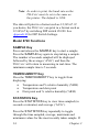
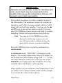
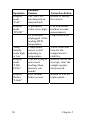
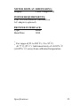
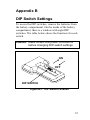
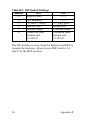
1
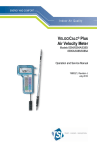
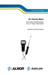
Indoor Air Quality
Model 8720/8722
TM
TH-CALC
Temperature and
Humidity Meters
Operation and Service Manual
1980397, Revision D
July 2006
Model 8720/8722
TM
TH-CALC
Temperature and
Humidity Meters
Operation and Service Manual
1980397, Revision D
July 2006
SHIP/MAIL TO:
TSI Incorporated
500 Cardigan Road
Shoreview, MN 55126-3996
USA
U.S.
Sales and Customer Service:
(800) 874-2811/(651) 490-2811
Fax:
(651) 490-3824
INTERNATIONAL
Sales and Customer Service:
(001 651) 490-2811
Fax:
(001 651) 490-3824
E-mail address:
[email protected]
Website:
http://www.tsi.com
EUROPE
TSI AB:
+46 8 595 132 30
Fax:
+46 8 595 132 39
TSI GmbH:
+49 241 52 30 30
Fax:
+49 241 52 30 349
Copyright©
TSI Incorporated / 2000–2006 / All rights reserved.
Address
TSI Incorporated / 500 Cardigan Road / Shoreview, MN 55126 /
USA
Fax No.
(651) 490-3824
Limitation of Warranty and Liability (effective July 2000)
Seller warrants the goods sold hereunder, under normal use and
service as described in the operator's manual, shall be free from
defects in workmanship and material for twenty-four (24) months, or
the length of time specified in the operator's manual, from the date of
shipment to the customer. This warranty period is inclusive of any
statutory warranty. This limited warranty is subject to the following
exclusions:
a. Hot-wire or hot-film sensors used with research anemometers,
and certain other components when indicated in specifications,
are warranted for 90 days from the date of shipment.
b. Parts repaired or replaced as a result of repair services are
warranted to be free from defects in workmanship and material,
under normal use, for 90 days from the date of shipment.
c. Seller does not provide any warranty on finished goods
manufactured by others or on any fuses, batteries or other
consumable materials. Only the original manufacturer's warranty
applies.
d. Unless specifically authorized in a separate writing by Seller,
Seller makes no warranty with respect to, and shall have no
liability in connection with, goods which are incorporated into
other products or equipment, or which are modified by any
person other than Seller.
The foregoing is IN LIEU OF all other warranties and is subject to
the LIMITATIONS stated herein. NO OTHER EXPRESS OR
IMPLIED WARRANTY OF FITNESS FOR PARTICULAR
PURPOSE OR MERCHANTABILITY IS MADE.
TO THE EXTENT PERMITTED BY LAW, THE EXCLUSIVE
REMEDY OF THE USER OR BUYER, AND THE LIMIT OF
SELLER'S LIABILITY FOR ANY AND ALL LOSSES, INJURIES,
OR DAMAGES CONCERNING THE GOODS (INCLUDING
iii
CLAIMS BASED ON CONTRACT, NEGLIGENCE, TORT,
STRICT LIABILITY OR OTHERWISE) SHALL BE THE
RETURN OF GOODS TO SELLER AND THE REFUND OF THE
PURCHASE PRICE, OR, AT THE OPTION OF SELLER, THE
REPAIR OR REPLACEMENT OF THE GOODS. IN NO EVENT
SHALL SELLER BE LIABLE FOR ANY SPECIAL,
CONSEQUENTIAL OR INCIDENTAL DAMAGES. SELLER
SHALL NOT BE RESPONSIBLE FOR INSTALLATION,
DISMANTLING OR REINSTALLATION COSTS OR CHARGES.
No Action, regardless of form, may be brought against Seller more
than 12 months after a cause of action has accrued. The goods
returned under warranty to Seller's factory shall be at Buyer's risk of
loss, and will be returned, if at all, at Seller's risk of loss.
Buyer and all users are deemed to have accepted this LIMITATION
OF WARRANTY AND LIABILITY, which contains the complete
and exclusive limited warranty of Seller. This LIMITATION OF
WARRANTY AND LIABILITY may not be amended, modified or
its terms waived, except by writing signed by an Officer of Seller.
Service Policy
Knowing that inoperative or defective instruments are as detrimental
to TSI as they are to our customers, our service policy is designed to
give prompt attention to any problems. If any malfunction is
discovered, please contact your nearest sales office or representative,
or call TSI's Customer Service Department at (800) 874-2811 (USA)
and 1 (651) 490-2811 (International).
iv
CONTENTS
CHAPTERS
1. Unpacking and Parts Identification .......... 1
Optional Accessories.................................... 2
Parts Identification ........................................ 3
2. Setting-Up.................................................... 5
Supplying Power to the TH-CALC ................. 5
Installing the Batteries ............................... 5
Using the Optional AC Adapter ................. 5
Selecting the Display Units........................... 5
Baud Rate..................................................... 6
Setting the Real-Time Clock......................... 6
Connecting the Optional Portable Printer..... 7
Connecting to a Computer............................ 8
Data Acquisition (Polling) ............................. 8
3. Operation ................................................... 11
Keypad Functions ....................................... 11
ON/OFF Key ............................................... 11
Arrow Keys (▲▼)....................................... 12
Printing Data Using the Optional
Portable Printer........................................ 12
Model 8720 Functions ................................ 14
SAMPLE Key .............................................. 14
TEMP/HUMIDITY Key ................................ 14
STATISTICS Key........................................ 14
Model 8722 Functions ................................ 15
ENTER Key ................................................ 15
TEMP Key................................................... 15
DEWPOINT Key ......................................... 16
HUMIDITY Key ........................................... 16
WETBULB Key ........................................... 16
v
%OA (Percent Outside Air) Key.................. 16
SAMPLE INTERVAL Key............................ 20
SAMPLE Key .............................................. 20
Setting Data Storage Options .................. 20
Discrete Data Logging (Single Point
Measurements)..................................... 21
Continuous Data Logging (Multiple
Readings Over Time) ........................... 21
NEXT TEST (clear) Key.............................. 22
STATISTICS (review data) Key .................. 23
To View Statistics .................................... 23
To Review Data ....................................... 23
Downloading Data to A Computer .............. 24
4. Maintenance .............................................. 27
Probe Tip .................................................... 27
Recalibration ............................................... 27
Cases .......................................................... 27
Storage ....................................................... 27
5. Troubleshooting........................................ 29
APPENDIXES
A. Specifications............................................ 31
B. DIP Switch Settings .................................. 35
vi
Chapter 1
Unpacking and Parts
Identification
Carefully unpack the instrument and accessories from
the shipping container. Check the individual parts
against the list of components in Table 1-1. If any are
missing or damaged, notify TSI or your local
distributor immediately.
Table 1-1: List of Components
Qty
Item Description
1
Or
4
1
1
1
1
Model 8720 TH-CALC and
Carrying Case
Model 8722 TH-CALC and
Carrying Case
AA Alkaline Batteries
Operation and Service Manual
Calibration Certificate
Computer Interface Cable
(with Model 8722 only)
Downloading Software Disk
(with Model 8722 only)
Part
8720
1319253
8722
1319114
1208013
1980397
1083173
8940
800832
1
Optional Accessories
The following contains information for optional
accessories for the TH-CALC.
Table 1-2: Optional Accessories
Qty
Item Description
1
1
2
Optional AC Adapter
115 V, NEMA-5
230 V, European CEE 7/16
230 V, Great Britain
240 V, Australian
Portable Printer
Part
2613033
2613078
800169
2613106
Chapter 1
Parts Identification
4
2
5
1
3
Figure 1-2: TH-CALC Temperature and
Humidity Meter
1.
2.
3.
4.
5.
Keypad
Display
Printer/Computer Interface Port
Temperature and Humidity Probe
Battery Access Cover
Unpacking and Parts Identification
3
Chapter 2
Setting-Up
Supplying Power to the TH-CALC
The TH-CALC can be powered in one of two ways:
four size AA batteries or the optional AC adapter.
Installing the Batteries
Insert four AA batteries as indicated by the
diagram located on the inside of the battery
compartment. TSI ships the unit with alkaline
batteries. The TH-CALC is designed to operate
with alkaline batteries. Other batteries are not
recommended because of short life and the danger
of battery acid leakage. At 15% battery life
remaining, the battery light will indicate the
batteries need to be changed.
Using the Optional AC Adapter
The optional AC adapter allows you to power the
TH-CALC from a wall outlet. When using the AC
adapter, the batteries (if installed) will be
bypassed. The AC adapter is not a battery charger.
Selecting the Display Units
The TH-CALC is capable of displaying the measured
values in several different measurement units, as
shown in Table 2-1.
5
Table 2-1: Choices of Measurement Units
Temp/
DIP switch
Humidity Ratio and
Dew point/
setting #5
Absolute Humidity
Wet bulb
OFF
ON
lbs/lb and lbs/ft3
g/kg and g/m3
°F
°C
If you wish to change the display units on your
TH-CALC, see Appendix B for DIP Switch location and
settings.
Baud Rate
The TH-CALC Model 8720 has a set baud rate of 1200,
which allows it to communicate with the optional
portable printer. The Model 8722 has a variable baud
rate that is used when downloading or printing data
from the instrument. By increasing the baud rate, the
data will download faster.
The instrument baud rate is displayed during the initial
power up sequence. To change the baud rate, press and
hold either ▲or ▼ keys during power-up sequence
while baud rate is displayed. Release the key when the
TH-CALC beeps twice. Use the ▲or ▼ keys to scroll
through the available values of 1200, 2400, 4800, 9600
and 19,200. Press ENTER to set the value that is
displayed.
Setting the Real-Time Clock
The TH-CALC has an internal clock that keeps track of
the time (the format is HH.MM where HH is the hour
in 24-hour format, and MM is minutes) and the date. It
is very important to set the time and date correctly,
6
Chapter 2
otherwise date and time stamping of recorded data will
not be correct.
To set the time and date, press and hold either ▲ or ▼
keys during the power-up sequence when the time is
displayed. Release the keys when the TH-CALC beeps
twice. You will have an opportunity to view and/or
change the hours, minutes, year, month and day in
sequence. Use ▲ or ▼ key to change any settings. Use
the ENTER key to store each setting and advance to
the next one.
Connecting the Optional Portable Printer
To connect the printer to the TH-CALC, do the
following:
1.
Ensure that the TH-CALC and printer are off.
2.
Locate the printer interface cable and connect the
9-pin end labeled PRINTER to the printer and the
other end to the communications port on the
TH-CALC monitor.
3.
Turn on the TH-CALC; then turn on the printer.
Note:
Always turn on the TH-CALC before
turning on the printer. If the printer prints
question marks (??????), asterisks
(******), or random characters, reset it by
turning it off and then on again. If
necessary, refer to the Portable Printer
Manual.
Setting-Up
7
Connecting to a Computer
Use the Computer Interface Cable provided with the
TH-CALC Model 8722 to connect the instrument to a
computer for remote polling or for downloading stored
data. Connect the 9-pin end labeled “COMPUTER” to
the computer COM port and the other end to the data
port of the TH-CALC. A 9-pin to 25-pin adapter will be
required if your computer has a 25-pin serial port
connector.
For more information on how to download stored data
see Downloading Data to a Computer section in
Chapter 3. For polling instructions, see the following
Data Acquisition (Polling) section.
Data Acquisition (Polling)
The TH-CALC is designed to allow the user to perform
polling through the use of a computer. To do this, the
user’s computer must be connected and in terminal
mode. The baud rate for the computer and the
TH-CALC must be set to the same value. For details on
viewing or changing the baud rate, see Changing the
Baud Rate section in Chapter 2. You then must send an
upper case V to the instrument.
You must write your own routine (program) to obtain
information at specific intervals from the TH-CALC.
The meter will only send information when the
SAMPLE key is pressed or after the computer has sent
a “V” command to the TH-CALC.
8
Chapter 2
Field Calibration
Temperature and humidity have a field calibration
adjustment available. The temperature adjustment can
add or subtract a number of degrees. The range is
±9.99ºF (± 5.55°C). Calibration can be done in either
ºF or ºC mode. Humidity adjustment adds or subtracts
a constant percentage. The range is ± 12.0% relative
humidity. The procedure for field adjustment is as
follows:
Turn off the instrument, flip DIP switch #7 to “ON.”
Turn the TH-CALC on again.
On the Model 8720, press and hold the SAMPLE key
to enter calibration mode. The display will begin a
countdown from 5 to 0. Release the key when 0 is
displayed. The top line of the display will show the
adjustment number and the bottom line will show the
actual reading value. Use the ▲ and ▼ keys to change
the adjustment number and press SAMPLE key to
accept. Press the TEMP/HUMIDITY key to make
corrections on the other parameter. When finished, turn
the instrument off and flip DIP switch #7 to “off.”
On the Model 8722, press and hold the TEMP or
HUMIDITY key to enter the calibration mode for that
parameter. To enter the calibration mode for the RTD,
make sure the RTD is plugged in. Press the TEMP key
until “rtd” shows on the display, then press and hold
the TEMP key.
The display will begin a countdown from 5 to 0.
Release the key when 0 is displayed. The top line of
the display will show the adjustment number (factory
setting is 0.0) and the bottom line will show the actual
Setting-Up
9
reading value. Use ▲ and ▼ to change the adjustment
number and press ENTER to accept. If necessary,
repeat the above sequence for the other parameters.
When finished, turn the instrument off and flip DIP
switch #7 to “off.”
10
Chapter 2
Chapter 3
Operation
Keypad Functions
When pressing the keys on the front panel, the
TH-CALC will beep to confirm the function. If you
press a key and the TH-CALC does not beep, then the
TH-CALC does not allow that function during the
selected mode.
WARNING! Do not expose the sensing probe to
excessive heat—it can damage the
sensors and probe.
ON/OFF Key
Press the ON/OFF key to turn the TH-CALC on and
off. When the instrument is first turned on it goes
through a preprogrammed power-up sequence that
includes an internal self-check (when all displayable
items are shown). The TH-CALC begins by displaying
percentage of battery life remaining (accurate for
alkaline batteries only). At this point, the Model 8720
will start measuring temperature and % relative
humidity.
The Model 8722 also displays the percentage of
memory available, baud rate, time (HH.MM) and
entered barometric pressure. At this point, the Model
8722 will start measuring temperature and % relative
humidity.
11
If a problem is detected, the display will light ‘CAL’ to
indicate that it should be returned for servicing and
calibration.
Note: To skip the start-up displays, press
ENTER at any time during the powerup sequence.
Arrow Keys (▲▼)
The two arrow keys are used to scroll through and
select values as needed for TH-CALC functions. They
are also used while in field calibration mode.
On the Model 8722, pressing either ▲ or ▼key on the
start-up sequence while baud rate, time or barometric
pressure are displayed will allow you to change them.
Use the ▲ or ▼key to adjust, and press ENTER to
accept.
Printing Data Using the Optional Portable
Printer
If the optional Portable Printer is connected, the
following will be printed while pressing the following
keys:
On the Model 8720:
•
SAMPLE key:
•
STATISTICS key:
12
SAMPLE TIME: (time, units)
AVG: (top line average, units)
AVG: (bottom line average, units)
SAMPLE TIME: (time, units)
Chapter 3
•
•
•
STATISTICS (again):
AVG: (top line average, units)
AVG: (bottom line average, units)
STATISTICS (again):
MAX: (top line max, units)
MAX: (bottom line max, units)
STATISTICS (again):
MIN: (top line min, units)
MIN: (bottom line min, units)
On the Model 8722:
•
•
•
•
•
•
SAMPLE key:
(top line sample #), sample value, units
(bottom line sample #), sample value, units
STATISTICS key:
AVG: (top line # samples), avg. value, units
AVG: (bottom line # samples), avg. value, units
STATISTICS (again)
MAX: (top line # samples), max value, units
MAX: (bottom line # samples), max value, units
STATISTICS (again):
MIN (top line # samples), min value, units
MIN (bottom line # samples), min value, units
CLEAR (and released before 0)
CLEAR SAMPLE
CLEAR (and released at 0)
CLEAR LOG MEMORY
Operation
13
Note: In order to print, the baud rate on the
TH-CALC must be set to the same as
the printer. The default is 1200.
The data will print in a format such as 12,345.67. If
you desire, the TH-CALC can print in a format such as
12.345,67 by switching DIP switch #8 ON. See
Appendix B for DIP Switch Settings.
Model 8720 Functions
SAMPLE Key
Press and release the SAMPLE key to start a sample.
Press the SAMPLE key again to stop taking a sample.
The number of seconds sampled will be displayed
followed by the average (‘AVG’) and then the
TH-CALC will return to measuring in real-time. The
minimum sample time is 5 seconds.
TEMP/HUMIDITY Key
Press the TEMP/HUMIDITY key to toggle from
displaying:
• Temperature and % relative humidity (%RH)
• Temperature and dew point
• Dew point and % relative humidity (%RH)
STATISTICS Key
Press the STATISTICS key to view time sampled (in
seconds or minutes) and average (‘AVG’).
Press the STATISTICS key repeatedly to toggle
through the time sampled, average, maximum and
minimum values for the most recently taken sample. If
14
Chapter 3
a printer is attached, the average, maximum and
minimum will print out as they are displayed.
Model 8722 Functions
The TH-CALC Model 8722 measures temperature and
% relative humidity and calculates dew point, wet
bulb, absolute humidity, humidity ratio and % outside
air. It also has the ability to data log, determine
statistics and recall individual data points. The
TH-CALC Model 8722 will retain data even after it is
turned off.
ENTER Key
Press the ENTER key to accept a value or condition.
In start-up mode, you can also press and hold the
ENTER key to skip the start-up sequence.
TEMP Key
Press the TEMP key to view the temperature from the
resistive temperature device (RTD). The letters “rtd”
will display on the top line of the display with the
temperature from the RTD on the bottom line.
Press the TEMP key again to read temperature from
the permanent probe.
Note: If the RTD becomes unplugged while in
RTD mode, the display will read
“over.” If the RTD is not plugged in
and the TEMP key is pressed, nothing
will happen.
Operation
15
DEWPOINT Key
Press the DEWPOINT key to display the dew point
measurement on the top line of the display.
HUMIDITY Key
Press the HUMIDITY key repeatedly to toggle through
the available humidity measurements of:
•
•
•
% relative humidity (%RH)
Absolute humidity (lbs/ft3 or g/m3)
Humidity ratio (lbs/lb or g/kg)
Absolute humidity and humidity ratio will
display in scientific notation. The top line
displays the number value and the bottom line
displays the exponent value.
WETBULB Key
Press the WETBULB key to display the wet bulb
measurement on the top line of the display.
%OA (Percent Outside Air) Key
The percent of outside air can be calculated according
to temperature using the following equation:
%OA= (TR-TS) / (TR-TO) x 100%
where
16
%OA
TR
TS
TO
= Percentage of outside air
= Temperature of return air
= Temperature of supply air
= Temperature of outside air
Chapter 3
IMPORTANT:
Samples should be taken at the Air Handling Unit
only, since there may be components in the
system that change the temperature that are not
evident upon initial examination.
The general procedure is to take a sample in each of
the four modes. The modes are return air, outside air,
supply air and %OA. Pressing sample while in %OA
mode will store all four samples. You may use the ▲
and ▼ keys to move from mode to mode. You may
press the %OA key at any time to exit back to normal
sampling. Details on the procedure are as follows:
Note: You may press the %OA at any time
during the following sequence to exit
the %OA procedure without saving any
data and to return to normal sampling.
Press the %OA key once to put the instrument in
return mode.
In return air mode, “RETURN” will appear on the
display. The current temperature value will display on
the bottom line of the display along with “----” (or the
last value taken for return air) on the top line. Press
SAMPLE once temperature has stabilized. Now the
sampled value will display on the top line.
If the sample is not acceptable or the temperature is not
yet stable, wait a minute and then take another sample
to overwrite the value on the top line.
Operation
17
Once the top line value is acceptable, press the ▲ key
to advance to outside air.
In outside air mode, “OA” will appear on the display
along with the current temperature on the bottom line
and “----” (or the last value taken for return air) on the
top line. Once the reading has stabilized, press
SAMPLE. The sampled value for outside air will
display on the top line with the current reading on the
bottom line.
If the sample is not acceptable or the temperature is not
yet stable, wait a minute and then take another sample
to overwrite the value on the top line.
Once the value is acceptable, press the ▲ key to
advance to supply air mode.
In supply mode, “SUPPLY” will appear on the display
along with the current temperature on the bottom line
and “----” (or the last value taken for return air) on the
top line. Once the supply air temperature has
stabilized, press SAMPLE. The sampled value for
outside air will display on the top line with the current
reading on the bottom line.
If the sample is not acceptable or the temperature is not
yet stable, wait a minute and then take another sample
to overwrite the value on the top line.
Once the value is acceptable, press the ▲ key to
advance to %OA.
18
Chapter 3
Note: At any time, you may use the ▲ and ▼
key to move between the 3 modes
(return, outside and supply air) to
review or change the values.
“OA%” will appear on the display along with the %
outside air value. To put this %OA value and the
values from the three other modes into memory, press
the SAMPLE key.
Note: “Err” will display if not enough
information is available or a negative
% value is calculated.
To make changes to one of the other three readings
without putting these values to memory yet, press the
▲ and ▼ keys to review the values and press
SAMPLE to overwrite the value.
To exit this procedure completely without putting any
values to memory, press the %OA key.
To take another % outside air measurement, make sure
you pressed SAMPLE to put the values to memory.
Then use the ▲ and ▼ keys to review the
measurements and take new samples for supply and
return. If you suspect the outside air temperature has
changed, you will have to retake that sample as well.
The process will be the same as outlined except that
instead of “----” displaying on the top line, your
previous sampled values will display.
Operation
19
SAMPLE INTERVAL Key
Press and release the SAMPLE INTERVAL key to
view the current mode of either discrete data logging
(‘dISC’) or continuous data logging (‘COnt’). Use ▲
and ▼ to toggle from one to the other and press
ENTER to accept the choice.
If you chose “dISC,” the instrument will return to
normal operation.
If you chose continuous data logging, “LOG” will
display along with the logging interval choices. Use the
▲ and ▼ keys to scroll through the choices of 5 s, 10
s, 20 s, 30 s, 1 m, 2 m, 5 m, 10 m,15 m, 20 m, 30 m, 60
m. Press ENTER to accept the choice and return to
measuring mode.
SAMPLE Key
Setting Data Storage Options
You can set parameters to be stored even if they
are not displayed when a sample is taken.
In this section the terms “On” and “OFF” are
referred to. The following brief explanations may
help to understand what function is being
performed. “On” means that the parameter will
record whenever the SAMPLE key is pressed.
“OFF” means that the parameter will not be stored.
Press and hold the SAMPLE key to view, enter, or
change data storage options. Use ▲ and ▼ key to
toggle between “On” and “OFF,” then press
20
Chapter 3
ENTER to accept the setting. Continue this
procedure for every parameter.
Discrete Data Logging (Single Point
Measurements)
Discrete data logging allows you to record single
data points. The instrument must first be in
discrete data logging mode (default). See
SAMPLE INTERVAL key section above.
Press the SAMPLE key to take a sample. While
the sample is being taken, “SAMPLE” will flash
on the display along with the sample number on
each line for each parameter. The sampling will
last for 5 seconds. Then the TH-CALC will display
the sample values that were recorded.
Continuous Data Logging (Multiple
Readings Over Time)
Continuous data logging allows you to record
samples continuously. To get into data logging
mode and to select a logging interval, see
SAMPLE INTERVAL key section above.
Pressing the SAMPLE key once begins the
sampling process. The instrument will display
“LOG” briefly indicating samples will be
recorded. After one logging interval has passed
and whenever a sample is recorded, the instrument
will display “SAMPLE” briefly along with the log
sample value. The instrument continues taking
samples until you press the SAMPLE key a
second time. One sample is taken every logging
Operation
21
interval and each sample is an average over the
entire sample interval.
The display will then scroll through the number of
samples stored, test ID number and sample
average for that test ID. To see maximum,
minimum, or individual data points, please see
STATISTICS (review data) Key section.
NEXT TEST (clear) Key
Press NEXT TEST (clear) to advance to the next test
ID. If the current test ID does not have anything stored,
it will not advance to the next test ID.
Note: Upper case key functions are the
primary key functions. Lower case
functions are press and hold functions.
The TH-CALC will automatically increment the test ID
number under the following conditions:
•
•
•
•
•
turning off the TH-CALC (if there is stored data)
taking a continuous data logging sample
taking discrete samples after taking continuous
sample
taking a %OA measurement after a normal sample
taking a normal sample after a %OA measurement
To clear the last sample, press and hold the NEXT
TEST (clear) key and the display will begin a
countdown from 5 to 0. Release the key at any time
during the countdown before zero is displayed. The
display will flash “CLEAR SAMPLE”
22
Chapter 3
To clear all memory, keep holding key during the
countdown. Release the key while 0 is displayed. The
display will beep twice and flash ‘CLEAR LOG.’
Note: If you release the key after 0 is displayed, it
will not beep, and nothing will be deleted.
Note: Only the last sample recorded can be
cleared without clearing the entire
memory. You cannot go back to a
previous test ID and erase any of the
values. You cannot add data to a
previous test ID. Sample clear does
not work in continuous data logging
mode.
STATISTICS (review data) Key
The STATISTICS (review data) key has two
purposes. One is to view the statistics for the currently
displayed parameter and the other is to review data for
a particular test ID, including individual sample values.
To View Statistics
Press STATISTICS (review data) key to view
statistics for the parameter currently shown on the
display. The test ID, number of samples and
finally the average will be displayed. Press
STATISTICS (review data) again (before the
average disappears from the display) to toggle
through maximum and minimum.
To Review Data
Press and hold STATISTICS (review data) key.
The TH-CALC will beep twice. Release the key
Operation
23
and the test ID number will be displayed. Use the
▲ or ▲ key to select the desired test ID. Press
ENTER to accept the test ID number. Use ▲ to
view average, maximum, minimum, total number
of samples, and individual sample numbers and
values for the selected test ID. The samples will be
displayed in the order that they were taken.
To view a different test ID, press STATISTICS
(review data) again to return to test ID. Use ▲ or
▼ key to choose a new test ID, then press ENTER
to accept the choice and continue as above to
review the data.
To review data of a different measurement type,
press the desired measurement button while AVG,
MAX, MIN, number of samples, or individual
sample is being displayed. For humidity ratio or
absolute humidity, press the HUMIDITY key to
toggle through those parameters. For the RTD,
press the TEMP key. If there is no data for that
measurement type “-----” will be displayed. Press
another measurement type key to view more data
or press ENTER to return to measuring mode.
Note: To view return air, supply air or
outside air individually, you must
download it to computer or print
out the values. %OA is reviewable
on-screen.
Downloading Data to A Computer
“LOGDAT” is a windows-based program from TSI
designed to download the data stored in the memory of
24
Chapter 3
the TH-CALC to a computer. This data includes the test
ID, measurement, unit of measure, and logging
interval. This data is date and time stamped. In
addition, the statistics for each test ID are provided.
The file containing the downloaded data is sorted and
tab delimited to allow it to be imported into a
spreadsheet for further data analysis.
TM
To install LogDat software, run the SETUP.EXE file
on the LogDat distribution disc. Once you open the
program, it is self-directing and provides all the
necessary instructions for downloading data.
To download data from the TH-CALC, connect the
supplied computer interface cable to the TH-CALC and
to a computer serial port. Any serial port from COM1
to COM4 can be used.
Operation
25
Chapter 4
Maintenance
Probe Tip
Periodically inspect the probe tip to ensure that it is
clean. Dust and oil deposits on the sensor may affect
the response time of the TH-CALC. To remove dust,
blow it off with a gentle stream of air.
Recalibration
To maintain a high degree of accuracy in your
measurements, TSI recommends that you return your
instrument for annual recalibration. For a nominal fee,
we will recalibrate the unit and return it to you with a
NIST (US National Institute of Standards and
Technology) traceable certificate. This ‘annual
checkup’ assures you of consistently accurate readings;
it is especially important in applications where strict
calibration records must be maintained.
Cases
If the instrument case or storage case needs cleaning,
wipe it off with a soft cloth and a mild detergent.
Never submerge the TH-CALC.
Storage
When storing the TH-CALC for more than a month,
TSI recommends removing the batteries. This prevents
possible damage due to battery leakage.
27
Chapter 5
Troubleshooting
Table 5-1 lists the symptoms, possible causes, and
recommended solutions for common problems
encountered with the TH-CALC. If your symptom is not
listed, or if none of the corrective actions solve your
problem, please contact TSI.
Table 5-1: Troubleshooting the TH-CALC
Possible
Symptom Causes
Corrective Action
No display
Battery
symbol is
blinking
Display
reads
"LO"
Unit not
switched on
Low or dead
batteries
Dirty battery
contacts
Batteries are low,
15% or less life
remaining
Wrong AC
adapter
Low AC line
voltage
Dirty battery
contacts
Switch on the
unit.
Replace the
batteries or plug in
the AC adapter.
Clean the battery
contacts.
Replace or
recharge batteries.
Replace with the
correct AC
adapter.
Correct the AC
line voltage or use
batteries.
Clean the battery
contacts.
29
Symptom
Display
reads
“CAL”
Display
reads
“OVER”
Temp.
initially
reads high
or low
Display
reads
“LOG
FULL”
Display
flashes
“Libatt”
30
Possible
Causes
The TH-CALC
has detected an
internal fault
A parameter
value is too high.
RTD became
unplugged while
reading RTD
temperature.
Temperature
sensor is still
adjusting to
temperature
You are trying to
enter more
readings than
memory can
handle
Low lithium
battery power
Corrective Action
Return to factory
for service.
Use an alternate
method to make
measurement.
Plug in the RTD
Allow sufficient
time for the
temperature to
stabilize.
Read or record the
average; clear the
sample register
and proceed.
Return to TSI for
replacement.
Chapter 5
Appendix A
Specifications
Specifications are subject to change without notice.
Specifications in parentheses () indicate metric
equivalents.
TEMPERATURE:
Range:
32 to 140 °F (0 to 60 °C)
Accuracy:
± 1.0 °F (± 0.6 °C)
Resolution:
0.1 °F (0.1 °C)
SECONDARY TEMP PROBE (optional):
Sensor Type:
RTD
Range:
-40 to 248 ○F (-40 to 120○C)
1
±1.0○F (±0.6○C)
Accuracy :
Resolution:
0.1○F (0.1○C)
RELATIVE HUMIDITY:
Sensor Type:
Thin-film capacitive
Range:
5% to 95% RH
Accuracy
±3.0% RH
Resolution:
0.1% RH
DEW POINT:
Range:
Resolution :
5 to 120 °F (-15 to 49°C)
0.1°F (0.1°C)
WET BULB (Model 8722):
Range:
40 to 140°F (5 to 60°C)
Resolution:
0.1○F (0.1○C)
31
ABSOLUTE HUMIDITY (Model 8722 only):
Range:
0.0000151 to 0.00491 lbs moisture/ft3 air
(0.24 to 79.0 g moisture/m3 air)
HUMIDITY RATIO (Model 8722 ):
Range:
0.00014 to 0.187 lbs moisture/lb dry air
(0.14 to 187 g moisture/kg dry air)
% OUTSIDE AIR (Model 8722):
Range:
0 to 100%
Resolution:
0.1%
INSTRUMENT TEMPERATURE RANGE:
Operating:
41 to 158°F (5 to 70°C)
Storage:
-4 to 158°F (-20 to 70°C)
LOGGING CAPABILITY (Model 8722):
Memory:
Up to 14,000 samples and 1,000
test id’s
Intervals:
5 sec, 10 sec, 15 sec, 20 sec, 30
sec, 60 sec, 2 min, 5 min, 10 min,
15 min, 20 min, 30 min,
60 min
METER DIMENSIONS:
3.9 in. × 6.6 in. × 1.5 in.
(100 mm × 168 mm × 38 mm)
METER PROBE DIMENSIONS:
Probe length:
5.81 in. (14.5 cm)
Probe diameter:
0.75 in. (1.9 cm)
METER WEIGHT:
Weight (with batteries):
32
1.16 lbs (0.53 kg)
Appendix A
METER DISPLAY DIMENSIONS:
Display:
2 line, 4-digit LCD
POWER REQUIREMENTS:
Four AA-size batteries (included) or
AC adapter (optional)
PRINTER INTERFACE:
Type:
Serial
Baud Rate:
1200
1
For range of 23 to 203○F (-5 to 95○C)
At 77○F (25○C). Add uncertainty of ±0.03%/○F
(±0.05%/○C) away from calibrated temperature
2
Specifications
33
Appendix B
DIP Switch Settings
To access the DIP switches, remove the batteries from
the battery compartment. On the inside of the battery
compartment, there is a window with eight DIP
switches. The table below shows the functions for each
switch.
Caution: Make certain that power is turned off
before changing DIP switch settings.
ON
1
OFF
8
DIP SWITCH
Figure B-1: DIP Switch Location
35
Table B-1: DIP Switch Settings
Switch
OFF
1-3
4
5
6
7
8
Must be OFF
Not assigned
°F, lbs/ft3, lbs/lb
Buzzer OFF
Normal Mode
American Date
Format and
12,345.67
ON
------------°C, g/kg, g/m3
Buzzer ON
Calibrate Mode
European Date
Format and
12.345,67
The ON position is away from the batteries and OFF is
towards the batteries. Always leave DIP switch #1-4
and #7 in the OFF position.
36
Appendix B
TSI Incorporated
500 Cardigan Road, Shoreview, MN 55126 U.S.A.
Tel: +1 651 490 2811 Toll Free: 1 800 874 2811
E-mail: [email protected]
P/N 1980397 Rev D.
Copyright © 2006 by TSI Incorporated
Printed in U.S.A.