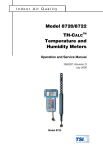
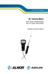
1
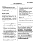
Ventilation Testing/Balancing
Model 8705
DP-CALC
Micromanometer
TM
Operation and Service Manual
1980381, Revision E
July 2006
Model 8705
DP-CALC
Micromanometer
TM
Operation and Service Manual
1980381, Revision E
July 2006
SHIP TO/MAIL TO:
TSI Incorporated
500 Cardigan Road
Shoreview, MN 55126-3996
USA
U.S. & INTERNATIONAL
Sales and Customer Service:
(800) 874-2811 /
+1 (651) 490-2811
Fax:
+1 (651) 490-3824
E-mail address:
[email protected]
Website:
http://www.tsi.com
EUROPE
Sales and Customer Service:
TSI AB
+46 18 52 7000
Fax:
+46 18 52 7070
TSI GmbH
+49 241 52 30 30
Fax:
+49 241 52 30 349
Copyright©
TSI Incorporated / 1999-2006 / All rights reserved.
Address
TSI Incorporated / 500 Cardigan Road / Shoreview, MN 55126 / USA
Fax No.
(651) 490-3824
LIMITATION OF WARRANTY AND LIABILITY (effective July 2000)
Seller warrants the goods sold hereunder, under normal use and service as described in the
operator's manual, shall be free from defects in workmanship and material for twenty-four (24)
months, or the length of time specified in the operator's manual, from the date of shipment to the
customer. This warranty period is inclusive of any statutory warranty. This limited warranty is
subject to the following exclusions:
a.
Hot-wire or hot-film sensors used with research anemometers, and certain other
components when indicated in specifications, are warranted for 90 days from the date of
shipment.
b.
Parts repaired or replaced as a result of repair services are warranted to be free from
defects in workmanship and material, under normal use, for 90 days from the date of
shipment.
c.
Seller does not provide any warranty on finished goods manufactured by others or on any
fuses, batteries or other consumable materials. Only the original manufacturer's warranty
applies.
d.
Unless specifically authorized in a separate writing by Seller, Seller makes no warranty
with respect to, and shall have no liability in connection with, goods which are
incorporated into other products or equipment, or which are modified by any person other
than Seller.
The foregoing is IN LIEU OF all other warranties and is subject to the LIMITATIONS stated
herein. NO OTHER EXPRESS OR IMPLIED WARRANTY OF FITNESS FOR
PARTICULAR PURPOSE OR MERCHANTABILITY IS MADE.
TO THE EXTENT PERMITTED BY LAW, THE EXCLUSIVE REMEDY OF THE USER OR
BUYER, AND THE LIMIT OF SELLER'S LIABILITY FOR ANY AND ALL LOSSES,
INJURIES, OR DAMAGES CONCERNING THE GOODS (INCLUDING CLAIMS BASED
ON CONTRACT, NEGLIGENCE, TORT, STRICT LIABILITY OR OTHERWISE) SHALL
BE THE RETURN OF GOODS TO SELLER AND THE REFUND OF THE PURCHASE
PRICE, OR, AT THE OPTION OF SELLER, THE REPAIR OR REPLACEMENT OF THE
GOODS. IN NO EVENT SHALL SELLER BE LIABLE FOR ANY SPECIAL,
CONSEQUENTIAL OR INCIDENTAL DAMAGES. SELLER SHALL NOT BE
RESPONSIBLE FOR INSTALLATION, DISMANTLING OR REINSTALLATION COSTS
OR CHARGES. No Action, regardless of form, may be brought against Seller more than 12
months after a cause of action has accrued. The goods returned under warranty to Seller's
factory shall be at Buyer's risk of loss, and will be returned, if at all, at Seller's risk of loss.
Buyer and all users are deemed to have accepted this LIMITATION OF WARRANTY AND
LIABILITY, which contains the complete and exclusive limited warranty of Seller. This
LIMITATION OF WARRANTY AND LIABILITY may not be amended, modified or its terms
waived, except by writing signed by an Officer of Seller.
Service Policy
Knowing that inoperative or defective instruments are as detrimental to TSI as they are to our
customers, our service policy is designed to give prompt attention to any problems. If any
malfunction is discovered, please contact your nearest sales office or representative, or call TSI's
Customer Service department at (800) 874-2811 (USA) or (001 651) 490-2811 (International).
CONTENTS
Chapters
1. UNPACKING AND PARTS IDENTIFICATION ............................ 1
Parts Identification ......................................................................... 1
2. SETTING-UP.................................................................................3
Supplying Power to the DP-CALC .................................................. 3
Installing the Batteries.............................................................3
Using the Optional AC Adapter............................................... 3
Selecting the Display Units............................................................ 3
Setting the Real-Time Clock.......................................................... 3
Changing the Baud Rate ...............................................................4
Connecting the Optional Portable Printer...................................... 4
Connecting to a Computer ............................................................4
3. OPERATION .................................................................................5
Overview........................................................................................5
Keypad Functions..........................................................................5
Common Terms.............................................................................5
ON/OFF Key..................................................................................6
Arrow Keys (▲▼).......................................................................... 6
ENTER (PRINT) Key..................................................................... 6
PRESSURE (HOLD TO ZERO) Key............................................. 7
VELOCITY Key..............................................................................7
FLOWRATE Key ........................................................................... 8
Flowrate (Calculated Using Velocity, Duct Area and K factor) ....... 8
Entering Shape, Size, And K Factor ....................................... 8
Flowrate (Calculated Using Pressure and Flow Factor)......... 9
Entering Flow Factor...............................................................9
ACTUAL/STANDARD Key ............................................................ 9
SAMPLE INTERVAL Key ............................................................10
SAMPLE Key...............................................................................10
Discrete Data Logging (Single Point Measurements) .......... 10
Continuous Data Logging (Multiple Readings Over Time) ... 10
NEXT TEST (clear) Key ..............................................................11
STATISTICS (review data) Key...................................................12
To View Statistics..................................................................12
To Review Data ....................................................................12
Downloading Data to a Computer ...............................................12
Data Acquisition (Polling) ............................................................13
i
4. MAINTENANCE ..........................................................................15
Recalibration................................................................................15
Cases...........................................................................................15
Storage ........................................................................................15
5. TROUBLESHOOTING ................................................................17
APPENDICES
A. SPECIFICATIONS.......................................................................19
B. DIP SWITCH SETTINGS ............................................................21
To obtain application information, check out our web site at
http://www.tsi.com and click “Ventilation Test Instruments” and then
“Applications Notes.”
or contact TSI at:
U.S. (800) 874-2811/(651) 490-2811 Fax: (651) 490-3824
International (1) 651-490-2811 Fax: (1) 651-490-3824
ii
Chapter 1
Unpacking and Parts Identification
Carefully unpack the instrument and accessories from the shipping
container. Check the individual parts against the list of components in
Table 1-1. If any are missing or damaged, notify TSI or your local
distributor immediately.
Table 1-1: List of Components
Qty
Item Description
1
Model 8705 DP-CALC
1
Carrying Case
4
AA Alkaline Batteries
1
Operation and Service Manual
2
4 Foot Sections of Rubber Tubing
1
Static Pressure Tip
1
Computer Interface Cable
1
Data Downloading Software
1
Pitot Tube (optional)
1
AC Adapter (optional)
115V, NEMA-5
230 V, European, CEE 7/16
230 V, Great Britain
240 V, Australian
Part/model
8705
1319114
1208013
1980381
801039
3002017
8940
800832
3002018
2613033
2613078
800169
2613105
Parts Identification
3
1
2
5
4
Figure 1-1: DP-CALC
1. Keypad
2. Display
3. Pressure Measurement Ports
4. RS-232 Printer Port
5. Battery Access Cover
1
Chapter 2
Setting-Up
Supplying Power to the DP-CALC
The DP-CALC can be powered in one of two ways: four size AA batteries or
the optional AC Adapter.
Installing the Batteries
Insert four AA batteries as indicated by the diagram located on the
inside of the battery compartment. TSI ships the unit with alkaline
batteries. The DP-CALC is designed to operate with either alkaline or
NiCd rechargeable batteries. Carbon-zinc batteries are not
recommended because of the danger of battery acid leakage. Typical
battery life at 20°C is 12 hours for alkaline batteries.
Using the Optional AC Adapter
The optional AC adapter allows you to power the DP-CALC from a wall
outlet. When using the AC adapter, the batteries (if installed) will be
bypassed. The AC adapter is not a battery charger.
Selecting the Display Units
The DP-CALC is capable of displaying the measured values in several
different measurement units, as shown in Table 2-1.
Table 2-1: Choices of Measurement Units
Pressure
Velocity
in. H2O
ft/min
mm Hg
m/s
Pa
FlowRate
ft3/min
m3/h
l/s
If you wish to change the display units on your DP-CALC refer to
Appendix B for DIP Switch Settings.
Setting the Real-Time Clock
The DP-CALC has an internal real-time clock that keeps track of the time of
day (the format is HH.MM where HH is the hour in 24-hour format and the
MM is minutes) and the date. It is very important for the DP-CALC to have
the time and date correctly set, otherwise date and time stamping of recorded
data will not be correct.
3
To set the time and date, press and hold either the ▲or ▼ key during the
power-up sequence while the time is displayed. Release key when the DPCALC beeps twice. You will have the opportunity to view and/or change the
hours, minutes, year, month, and day in sequence. Use the ▲or ▼ key to
change any setting. Press the ENTER key to store each setting and advance
to the next one.
Changing the Baud Rate
The DP-CALC has a variable baud rate that is used when downloading or
printing data from the instrument. By changing the baud rate to a higher
rate, the data will be downloaded faster.
Note: The baud rate must be equal to that of your computer or
printer.
The instrument baud rate is displayed during the initial power-up sequence.
To change the baud rate, press and hold either ▲or ▼ key during the
power-up sequence while the baud rate is displayed. Release the keys when
the DP-CALC beeps twice. Use the ▲or ▼ key to scroll through the
available values of 1200, 2400, 4800, 9600 and 19200. Press ENTER to set
the value that is displayed.
Connecting the Optional Portable Printer
To connect the printer to the DP-CALC, locate the Printer Interface Cable
(supplied with the optional printer) and connect the 9-pin end labeled
“PRINTER” to the printer and the other end to the data port of the DP-CALC.
If the printer prints question marks (??????), asterisks (******), or random
characters, reset it by turning it off and then on again. If necessary, refer to
the Portable Printer Manual.
Connecting to a Computer
Use the Computer Interface Cable provided with the DP-CALC to connect
the instrument to a computer for downloading stored data or for remote
polling. A 9-pin to 25-pin adapter may be required if your computer has a
25-pin serial port. For more information on how to download stored data
see Chapter 3 for Downloading Data to a Computer section.
4
Chapter 2
Chapter 3
Operation
Overview
The Model 8705 DP-CALC measures differential pressure, calculates
velocity, and calculates volumetric flowrate. It has data logging capability,
and can store individual readings and calculate statistics.
Keypad Functions
When pressing the keys on the front panel, the DP-CALC will beep to
confirm the function. If you press a key and the DP-CALC does not beep,
then the DP-CALC does not allow that function during the selected mode.
Common Terms
In this manual there are several terms that are used in different places. The
following is a brief explanation of the meanings of terms.
Sample: Consists of all of the measurement parameters stored each
time the SAMPLE key is pressed, or after each logging interval has
passed. The maximum number of samples is 1000.
Test ID: A group of samples. A test ID can contain one sample or up
to 1000 samples. The statistics (average, minimum, maximum and
count) are calculated for each test ID. The maximum number of test
IDs is 500.
Time Constant: The time constant is an averaging period. It is used to
dampen the display. If you are experiencing fluctuating flows, a longer
time constant will lessen those fluctuations. The display will update
every second, but the displayed reading will be the average over the last
time constant period. For example, if the time constant is 10 seconds,
the display will update every second, but the displayed reading will be
the average from the last 10 seconds. This is also referred to as a
“moving average.” The time constant is adjusted using the SAMPLE
INTERVAL key. See the SAMPLE INTERVAL key section later in
this chapter for more detail.
Logging Interval: The logging interval is a frequency period that the
instrument will log readings. For example, if the logging interval is set
to 30 minutes, readings will be taken and recorded once every 30
minutes.
5
K Factor: The K factor is a constant that corrects for flow irregularities
and is typically close to 1.00. This K factor is defined by the user, by
doing a duct traverse to find average velocity. Then a K factor can be
figured and assigned for a specific location within the duct. Flowrate is
then figured by multiplying velocity times area times the K factor.
Flow Factor: A constant supplied by the manufacturer of duct work,
piping, or any other obstruction to airflow. These manufacturers will
specify a specific location for a pressure measurement and the flow
factor corresponding with the location. Flowrate is figured by
multiplying flow factor by the square root of the pressure. Contact TSI
for more information about flow factors.
ON/OFF Key
Press the ON/OFF key to turn the DP-CALC on and off. When the
instrument is first turned on it goes through a preprogrammed power-up
sequence that includes an internal self-check (when all displayable items are
shown). Then the DP-CALC displays percentage of battery life, percentage
of (“LOG”) memory available, baud rate, time (HH.MM), entered
barometric pressure, entered temperature, and then the DP-CALC begins
taking pressure readings.
Note: To skip start-up sequence, press and hold ENTER any time
after the internal self-check.
Arrow Keys (▲▼)
The two arrow keys are used to scroll through and select values as needed
for DP-CALC functions. Pressing either arrow key on the start-up sequence
will allow you to change the baud rate, barometric pressure, temperature or
time.
ENTER (PRINT) Key
Press the ENTER key to accept a value or condition. In start-up mode, you
can also press and hold the ENTER key anytime after the internal self-check
to skip the start-up sequence.
Press the ENTER (Print) key momentarily to print information on the
optional Portable Printer.
If the optional Portable Printer is connected the following will be printed
while pressing the following keys:
•
•
•
6
ENTER key: sample value, units
SAMPLE key: (sample #), sample value, units
STATISTICS key: AVG (# of samples), average, units
Chapter 3
•
•
•
•
•
•
•
•
STATISTICS (again): MAX, (# of samples), max value, units
STATISTICS (again): MIN, (# of samples), min value, units
NEXT TEST: NEW TEST ID: #
CLEAR (and released before 0): SAMPLE CLEAR
CLEAR (and released at 0): CLEAR LOG MEMORY
PRESSURE (and hold): ZERO PRESSURE
ACTUAL/STANDARD:
FLOW = ACTUAL
(or FLOW = STANDARD)
When viewing statistics, the statistics shown on the display for the current
test ID will be printed automatically when the STATISTICS key is pressed.
When reviewing data, nothing will print. When taking a sample, the reading
will be printed automatically each time the SAMPLE key is pressed. Any
change made to K factor or duct size or shape will print the new shape, size
or K factor value.
To print all values stored in memory, press and hold the ENTER (Print) key
and the display will begin a countdown from 5 to 0. Release the key when 0
is displayed. The instrument will beep twice to confirm that it will print
everything in memory.
Note: In order to print, the baud rate of the DP-CALC must be
set to the same as the printer (default is 1200).
PRESSURE (HOLD TO ZERO) Key
Press the PRESSURE key to display pressure. Press and hold for three
seconds to zero the pressure reading. The unit will double beep to confirm
that the pressure has been zeroed.
Note: Make sure that all tubing is disconnected or open to
ambient conditions before zeroing.
To measure pressure, tubing must first be connected to the pressure ports on
the top back of the unit. Connect the other ends of the tubing to the
measurement device or pressure source, with the more positive pressure
connected to the port marked “+” and the more negative pressure connected
to the port marked “-”. When the pressure source is connected the same way
the pressure ports are marked, the meter will display a positive number.
VELOCITY Key
Press the VELOCITY key to display velocity. The velocity will be
displayed in ft/min or m/s depending on the setting of DIP switch #1 (refer
to Appendix B).
Operation
7
FLOWRATE Key
Press the FLOWRATE key to display volumetric flowrate. The DP-CALC
can calculate flowrate in one of two ways. Both methods are available for
use any time you are in flowrate mode.
The first method to calculate flowrate is by multiplying velocity times the
flow area times a K factor. This K factor is defined by the user, and is
usually close to 1.00.
The DP-CALC can also calculate flowrate with manufacturer supplied flow
factors. These flow factors are different from K factors in that they are
defined by the manufacturer of the airflow product. The specific location
where pressure measurements are to be taken is also defined by the
manufacturer. In this case, flowrate equals the flow factor times the square
root of the pressure.
Flowrate (Calculated Using Velocity, Duct Area and K factor)
Flowrate can be calculated for a round, square or rectangular duct. You
must first indicate the shape and size of the duct or other area through
which you want to measure flowrate. The DP-CALC displays the
volumetric flowrate in ft3/min, m3/h or l/s, depending on the setting of
DIP switches #1 and #2 (refer to Appendix B).
Entering Shape, Size, And K Factor
With the DP-CALC in flowrate mode, press and hold the ▲ or ▼ key
until the meter beeps. Use the ▲ or ▼ key to toggle between circle,
rectangle and pressure symbols. Press the ENTER key to accept a
shape and move to selection of the size. See the following section for
information on selecting the pressure symbol.
For a circular flow shape, the DP-CALC will ask for the diameter of the
circular area. Use the ▲ or ▼ key to select the diameter of the circular
area. Press the ENTER key to accept the size.
For a rectangular flow shape, the DP-CALC will ask for two dimensions.
Use the ▲ or ▼ key to select the horizontal dimension, then press the
ENTER key. Use the ▲ or ▼ key to select the vertical dimension, then
press the ENTER key.
Now the display will flash Kf and display a number. To select a stored
K-factor, use the ▲ key. Scroll through the five existing K factors,
pausing to allow the DP-CALC to display the value of each.
If the K factor needs to be changed, select K-factor #5. Wait a few
seconds for the instrument to display the K-factor. Use the ▲ and ▼
8
Chapter 3
keys to adjust the value and press the ENTER key to accept the Kfactor and begin measuring flowrate.
Note: Each time you select or change a K factor, the selected
or changed K factor will be stored in memory slot #1. The
other K factors will shift slots. The previous #1 K factor will
become #2, #2 will become #3 and so on. This may result in
losing the #5 slot value when a new K-factor value is added.
Flowrate (Calculated Using Pressure and Flow Factor)
This flowrate is calculated by multiplying the square-root of the
pressure reading by a manufacturer-supplied flow factor. This flowrate
calculation method is applicable for diffusers that contain pressure taps
designed for this purpose and for certain flow stations.
Note: When using this option, make sure that the DPCALC pressure units and the flowrate units provided by
the diffuser manufacturer correspond. If they don’t
match, the calculated flowrate will be incorrect.
Entering Flow Factor
With the DP-CALC in flowrate mode, press and hold the ▲ or ▼ key
until the meter beeps. Use the ▲ or ▼ key to scroll through the circle
and rectangle, and pressure symbols. Press the ENTER key to accept
the pressure symbol and move to the selection of the flow factor value.
The flow factor will be stored in the K factor storage slots. However,
these two factors are not to be confused with each other. Use the ▲ or
▼ key to choose the flow factor, then press the ENTER key to begin
measuring flowrate.
ACTUAL/STANDARD Key
Press to toggle between displaying actual and standard velocity or flowrate.
Press and hold to view, enter, or change ambient conditions. When the key
is pressed and held, the pressure units will flash and the last barometric
pressure entered will be displayed. Use the ▲ or ▼ key to change the
barometric pressure and press ENTER to accept it. Then the temperature
units will flash and the last temperature entered will be displayed. Use the
▲ or ▼ key to change the temperature and press ENTER to accept it and
return to measuring mode. The ranges that can be entered are as follows:
Pressure: 15 to 40 in. Hg (381 to 1016 mm Hg), 29.92 in Hg (760 mm Hg) is
default; Temperature -80 to 800ºF (-62 to 426ºC), 70ºF (21.1ºC) is
default.
Operation
9
When standard velocity or flowrate is being measured, the “STANDARD”
symbol will be shown on the display. When actual velocity or flowrate is
being measured, no symbol will be shown on the display.
SAMPLE INTERVAL Key
The SAMPLE INTERVAL key is used to set the time constant and logging
intervals. Press to display current time constant. Use the ▲ or ▼ key to
scroll through the time constant choices, which are 1 s, 2 s, 5 s, 10 s, 15 s,
20 s, and LOG symbol, then press ENTER to accept the choice.
If LOG was chosen, use the ▲ or ▼ keys to scroll through the logging
interval choices, which are 2 s, 5 s, 10 s, 15 s, 20 s, 30 s, 1 min, 2 min,
5 min, 10 min, 15 min, 20 min, 30 min, 60 min and OFF. Press ENTER to
accept choice and return to measuring mode.
Note: To operate the instrument in discrete data logging (or
single point) mode, the logging interval must be set to OFF. To
operate the instrument in continuous data logging mode, the
logging interval must be set to something other than OFF.
SAMPLE Key
Samples will be stored each time you press the SAMPLE key. Parameters
will be stored according to the mode you are in as indicated in Table 3-1.
Table 3-1: Storage
Mode
Pressure
Velocity
Flowrate
Parameters Stored in Memory
Pressure
Velocity and Pressure
Flowrate, Velocity and Pressure
Discrete Data Logging (Single Point Measurements)
Discrete data logging allows you to record single data points. The
instrument must first be in discrete data logging mode (default). See
SAMPLE INTERVAL Key section above.
Press the SAMPLE key to take a sample. The sample number and
“COUNT” will display briefly. While the sample is being taken,
“SAMPLE” will flash on the display. The sampling will last for the
length of the set time constant. Then the DP-CALC will display the
value that was recorded.
Continuous Data Logging (Multiple Readings Over Time)
Continuous data logging allows you to record samples continuously. To
get into data logging mode and to select a logging interval, see
SAMPLE INTERVAL key section above.
10
Chapter 3
Pressing the SAMPLE key once begins the sampling process. The
instrument will display “LOG” briefly indicating samples will be
recorded, the instrument will display “SAMPLE” briefly along with the
log sample value. The instrument continues taking samples until you
press the SAMPLE key a second time. One sample is taken every
logging interval and each sample is an average over the entire logging
interval.
Note: If you attempt to set the logging interval at less
than the time constant, the DP-CALC will automatically
set the time constant equal to the logging interval.
The display will then scroll through the test ID number,
number of samples stored, and sample average for that test ID.
To see maximum, minimum, or individual data points, see
STATISTICS (review data) key section.
NEXT TEST (clear) Key
Press to advance to the next test ID. If the current test ID does not have
anything stored, it will not advance to the next test ID.
The DP-CALC will automatically increment the test ID number under the
following conditions:
•
•
•
•
turning off the DP-CALC (if there is stored data)
taking a sample with a different duct size or shape than the last stored
sample
taking a continuous data logging sample
taking discrete samples after taking a continuous data logging sample
To clear the last sample, press and hold the key and the display will begin a
countdown from 5 to 0. Release the key at any time during the countdown
before zero is displayed. The display will flash “SAMPLE CLr.”
To clear all memory, keep holding key during the countdown. Release the
key when 0 is displayed. The display will flash “CLr.”
Note: Only the last sample recorded (one sample total) can be
cleared without clearing the entire memory. You cannot go back
to a previous test ID and clear a single reading. Also, you cannot
add data to a previous test ID.
Operation
11
STATISTICS (review data) Key
The STATISTICS key has two purposes. One is to view the statistics for
the currently displayed parameter and the other is review data for a
particular test ID.
To View Statistics
Press STATISTICS to view statistics for the current mode. The count
will be shown first and then the test ID and then the average. Press
STATISTICS again (before the average disappears from the display) to
proceed to maximum and again to display minimum.
To Review Data
Press and hold the STATISTICS key. The DP-CALC will beep twice,
release the key and the test ID number will be displayed. Use the ▲ or
▼ key to select the desired test ID. Press ENTER to accept the test ID
number. Use the ▲ or ▼ key to select and view average, maximum,
minimum, count, and individual sample numbers with values for the
selected test ID. The samples will be displayed in the order that they
were taken, from the first sample of that test ID to the last.
To view a different test ID, press STATISTICS again to return to test
ID on the display. Use the ▲ or ▼ key to choose a new test ID then
press ENTER to accept the choice and continue as above to review the
data.
To review data of a different measurement type, press the desired
measurement typed button while AVG, MAX, MIN, COUNT or sample
ID being displayed. If there is no data for that measurement type,
“COUNT” and “----” will be displayed. Press another measurement
type key to view more data or press ENTER to return to measuring
mode.
Downloading Data to a Computer
“LogDat” is a Windows based program from TSI designed to download the
data stored in the memory of the Model 8705 DP-CALC to a computer. This
data includes the test ID, measurement, unit of measure, correction factors,
actual/standard parameter, flow area, and time constant. This data is date
and time stamped. In addition, the statistics for each test ID are provided.
The file containing the downloaded data is sorted and tab delimited to allow
it to be imported into a spreadsheet for further data manipulation.
TM
To install LogDat software, run the SETUP.EXE file on the LogDat
distribution disc. Once you open the program, it is self-directing and
provides all the necessary instructions for downloading data.
12
Chapter 3
To download data from the DP-CALC, connect the supplied computer
interface cable to the DP-CALC and to a computer serial port. Any serial
port from COM 1 to COM 4 can be used.
Caution: The data port of the DP-CALC is not intended for
connection to a public telecommunications network. Connect the
data port only to another RS232 port.
Data Acquisition (Polling)
The DP-CALC is designed to allow the user to perform polling through the
use of a computer. To do this, the user’s computer must be connected and
in terminal mode. The baud rate for the computer and the DP-CALC must be
set to the same value. For details on viewing or changing the baud rate, see
Changing the Baud Rate section in Chapter 2. You must then send an upper
case V to the instrument.
The user must write their own routine (program) to obtain information at
specific intervals from the DP-CALC. The meter will only send information
when the SAMPLE or ENTER (print) keys are pressed or after the
computer has sent a “V” command to the DP-CALC.
Operation
13
Chapter 4
Maintenance
The DP-CALC requires very little maintenance to keep it performing well.
Recalibration
To maintain a high degree of accuracy in your measurements, TSI
recommends that you return your instrument for annual recalibration. For a
nominal fee, we will recalibrate the instrument and return it to you with a
Certificate of Calibration and US National Institute of Standards and
Technology (NIST) traceability. This “annual checkup” assures you of
consistently accurate readings; it is especially important in applications
where strict calibration records must be maintained.
Cases
If the instrument case or storage case needs cleaning, wipe it off with a soft
cloth and isopropyl alcohol or a mild detergent. Never immerse the DPCALC.
Storage
When storing the DP-CALC for more than a month, removing the batteries is
recommended. This prevents damage due to battery leakage.
15
Chapter 5
Troubleshooting
Table 5-1 lists the symptoms, possible causes, and recommended solutions
for common problems encountered with the DP-CALC. If your symptom is
not listed, or if none of the solutions solves your problem, please contact
TSI.
Table 5-1: Troubleshooting the DP-CALC
Symptom
Possible Causes
Corrective Action
No display
Instrument not
Switch on the instrument.
switched on
Low or dead batteries
Replace the batteries or
plug in the AC adapter.
Dirty battery contacts
Clean the battery
contacts.
Display reads Low battery charge
Replace or recharge
"LO"
batteries.
Wrong AC adapter
Replace with the correct
AC adapter.
Low AC line voltage
Correct the AC line
voltage or use batteries.
Dirty battery contacts
Clean the battery
contacts.
Display reads The DP-CALC has
Return to factory for
"CAL"
detected an internal
service.
fault
Display says
The pressure or
Use an alternate
"OVER"
velocity is too high
measurement method.
Warning!
The pressure sensor is protected from damage for up to
7 psi (190 in. H2O 48 kPa or 360 mm Hg). At higher
pressures it can burst!
17
Appendix A
Specifications
Specifications are subject to change without notice.
Specifications in parentheses () indicate metric equivalents.
PRESSURE:
Range:
Accuracy:
Resolution:
-5 to +15 in. H2O (-1245 to 3735 Pa, -9.3 to 28.0 mm Hg)
1% of reading ± 0.005 in. H2O (±1 Pa, ±0.01 mm Hg)
0.0005 in. H2O (0.1 Pa, 0.001 mm Hg)
VELOCITY:
1
Range :
2
Accuracy :
250 to 15,500 ft/min (1.27 to 78.74 m/s)
1.5% of reading at 2,000 ft/min (10.00 m/s)
FLOWRATE:
3
Displayed Range :
K factor Range:
to 9,999,000 CFM (9,999,000 l/s, 9,999,000 m /hr)
0.01 to 999.9
3
INSTRUMENT TEMPERATURE RANGE:
Operating range:
32 to 158°F (0 to 70°C)
Storage range:
-40 to 185°F (-40 to 85°C )
LOGGING CAPABILITY:
Test ID’s
Up to 500 test ID’s
Samples:
Up to 1000 samples
Intervals:
1 sec, 2 sec, 5 sec, 10 sec, 20 sec, 30 sec, 60 sec, 2 min,
5 min, 10 min, 30 min, 60 min.
TIME CONSTANT:
Values:
1, 2, 5, 10, 15, or 20 seconds
POWER REQUIREMENTS:
Batteries:
Four AA-size Alkaline or NiCd rechargeable
AC adapter:
7 VDC nominal, 300 mA
Approx. battery life:
12 hours (Alkaline), 7 hours (NiCd)
PHYSICAL:
External dimensions:
Weight (with batteries):
Display:
4.0 in x 6.6 in x 1.5 in (102 mm x 168 mm x 38 mm)
0.76 lb. (0.35 kg)
4-digit LCD, 0.6 in (15 mm) digit height
PRINTER INTERFACE:
Type:
Serial
Selectable BAUD rates: 1200, 2400, 4800, 9600, 19800
1
2
3
Pressure velocity measurements are not recommended below 1,000 ft/min (5.00
m/s) and are best suited to velocities over 2,000 ft/min (10.00 m/s). Actual range is a
function of pressure, temperature and barometric pressure.
Accuracy is a function of converting pressure to velocity. Conversion accuracy
improves when actual pressure values increase.
Actual range is a function of maximum velocity, pressure, duct size, K factor,
temperature and barometric pressure.
19
Appendix B
DIP Switch Settings
To access the DIP switches, remove the batteries from the battery
compartment. On the inside of the battery compartment, there is a window
with eight DIP switches. The table below shows the functions for each
switch.
Caution: Make certain that power is turned off before
changing DIP switch settings.
Switch
1
Function
Imperial or
metric
Flowrate*
Pressure
Pressure**
Temperature
Calibration
Data Format
OFF
ft/min & ft3/min
ON
m/s
l/s
m3/h
in. H2O
Pa and mm Hg
Pa
mm Hg
ºF
ºC
Factory Calibration
User Calibration
Commas;
Decimals;
MM.DD.YY
DD.MM.YY
8
Not assigned
leave in OFF position
* To select flowrate to display l/s or m3/hr, DIP switch #1 must be in the
ON position.
** To select pressure to display Pa or mm Hg, DIP switch #3 must be in
the ON position.
2
3
4
5
6
7
Figure B - 1: DIP Switch Location
ON
1
OFF
8
DIP SWITCH
Figure B-1: DIP Switch Location
21
TSI Incorporated
500 Cardigan Road, Shoreview, MN 55126 U.S.A.
Tel: +1 651 490 2811 Toll Free: 1 800 874 2811 E-mail: [email protected]
P/N 1980381 Rev E.
Copyright © 2006 by TSI Incorporated
Printed in U.S.A.