1
9
.-
BY APPOINTMENT
TO
BY APPOINTMENT TO
HER MAJESTY W E E N ELIZABETH I1
HER MA J ESTY OUEEN ELIZABETH
MANUFACTURERS O F DAIMLER AND JAGUAR CARS
THE OUEEN MOTHER
MANUFACTURERS OF DAIMLER AND JAGUAR CARS
JAGUAR CARS LIMITED COVENTRY ENGLAND
JAGUAR CARS LIMITED COVENTRY ENGLAND
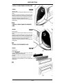
SERVICE MANUAL
VOLUME 4
Contains Sections
74. WHEELS AND TYRES
76. BODY
77. BODY REPAIR
80. HEATING AND VENTILATION SYSTEM
82. AIR CONDITIONING
84. WINDSCREEN WIPERS AND WASHERS
86. ELECTRICAL
88. INSTRUMENTS
Published hy Technical PublicaiionsJagUar Cars limited
Publication P a r t No JJM1 U 04 05 / 4 0
BY APPOINTMENT TO
HIS ROY4L HIGHNESS THE PRINCE OF WALES
MANUFACTURERSOF DAIMLER AND JAGUAR CARS
JAWAR CARS LMTED COVENTRY
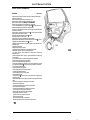
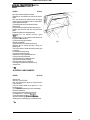
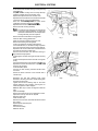
WHEELS A.NO TYRES
CONTENTS
DESCRIPTION
OPERATION
INDEX ..........................................
ROAD WHEEL .ONE ......................
SPARE WHEEL AND TOOL KIT ........
TYRES .90MY .............................
TYRES - 91MY .............................
TYRES .........................................
TD TYRES ....................................
WHEELS AND TYRES .....................
WHEELS .......................................
ILLUSTRATED ...........................
REMOVE AND REFIT ..................
STOWAGE ................................
DATA/PRESSURES.....................
DATA/PRESSURES.....................
DESC R IPTI0 N ............................
DESCRIPTION............................
TORQUE FIGURES .....................
DESCRIPTION............................
2000c
Issue 2
74-01
OPERATION
No
74.00.00
74.20.01
74.00.00
74.00.00
74.00.00
74.00.00
74.00.00
74.00.00
74.00.00
PAGE
No
74-02
74-19
74-20
74-04
74-06
74-07
74-10
74-1 1
74-12
WHEELS AND TYRES
J74 009
74-02
issue 2
WHEELS AND TYRES
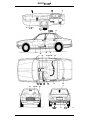
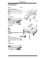
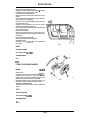
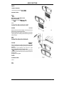
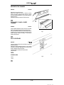
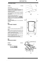
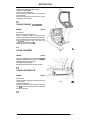
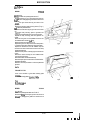
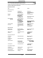
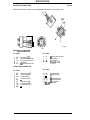
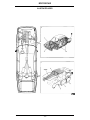
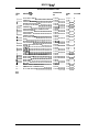
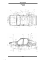
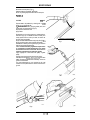
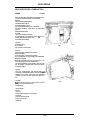
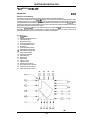
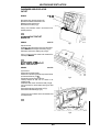
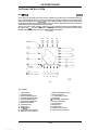
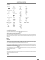
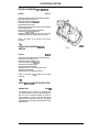
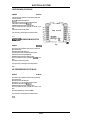
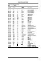
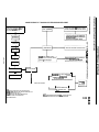
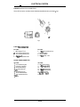
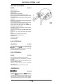
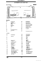
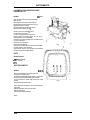
ILLUSTRATED INDEX - KEY
ITEM
No
DESCRIPTION
1 ............ ROAD WHEEL ...........................................
SPARE WHEEL AND TOOL KIT ....................
2 ...__......_
3 _........... WHEELS AND TYRES ................................
4 ............ WHEELS AND TYRES ................................
5 ............ WHEELS AND TYRES ................................
74-03
Issue
2
0PERATI0 N
No
PAGE
No
VOLUME
74.20.01
74.00.00
74.00.00
74.00.00
74.00.00
74-19
74-20
74-04
74-07
74-12
4
4
4
4
4
WHEELS AND TYRES
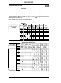
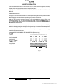
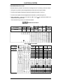
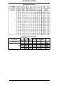
9OMY TYRES
74 .OO .OO
DATA/TYRE PRESSURES
North American Vehicles
TypeISize
Cold Inflation Pressure - Front
- Rear
Note:
Pirelli P5 205/70 VR 15 Cinturato (Tubeless)
33 Ibf/in2 (2.32kgfkm2, 228kPa; 2.27bar)
36 Ibf/in2 (2.53kgf/cm2, 248kPa; 2.48bar)
Pressures may be reduced by 6 Ibf/inZ (0.42kgfkm2, 41 kPa,0.41 bar) on front and rear tyres t o
obtain maximum comfort, provided the speed does not exceed 100mph (160 krn/h).
Rest of the World (ROW) Vehicles
TypeISize
Cold Inflation Pressure - Front
- Rear
Note:
Dunlop TD SP Super Sport D7, 220/65 VR 390 or
Michelin TDXV 220/65 VR 390 (Tubeless)
341bfh2 (2.39kgf/cm2, 235kPa, 2.35bar)
341bf/in2 (2.39kgfkrn2, 235kPa, 2.35bar)
Pressures may be reduced by 8 Ibf/in2 (0.56kgf/cm2, 55kPa, 0.55bar) on front and rear tyres t o
obtain maximum comfort, provided the speed does not exceed 100 mph (160 km/h).
Replacement tyres of different specifications andlor tread pattern, should not be fitted in mixed
form.
74-04
lssue 2
WHEELS AND TYRES
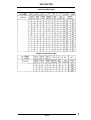
'SNOW TYRES
North American Vehicles
TypelSize
(complete sets only)
Pirelli M&S Winter 190 21 5/65 R 1 5 T
Cold Inflation Pressure
(maximum speed 1Oomph (160km/h))
- Front
- Rear
27 Ibf/inz (1.90kgf/cm2, 186kPa, 1.86bar)
30 Ibf/in2 (2.1 1kgflcm2, 207kPa, 2.07bar)
Cold Inflation Pressure
(maximum speed 120mph (190kmlh))
- Front
- Rear
33 Ibf/inz (2.32kgfkm2, 228kPa, 2.28bar)
36 Ibf/in2 (2.53kgfIcm2, 248kPa, 2.48bar)
Rest of the World (ROW) Vehicles
Type/Size
(complete sets only)
Dunlop TD SP 88 M A S (Tubeless)
Cold Inflation Pressure
(maximum speed 1Oomph (160km/h))
- Front
- Rear
26 Ibf/inz (1.83kgf/cm2, 179kPa, 1.79bar)
28 Ibf/in2 (1.97kgf/cm2, 193kPa, 1.93bar)
Cold Inflation Pressure
(maximum speed 120mph (190kmlh))
- Front
- Rear
3 4 Ibf/in2 (2.39kgfkm2, 235kPa, 2.35bar)
3 4 Ibf/inz (2.39kgf/cmz, 235kPa, 2.35bar)
Note:
Snow chains may be fitted to rear wheels only. Use Jaguar snow chains available from the Jaguar
accessory range (Champion 261 2-SM or Shur-grip).
Maximum speed with snow chains 30mph(48km/h).
Tyres may be fitted with studs provided maximum speed does not exceed 90rnph (145km/h).
Studs must be of the parallel shank type, 1Omm long, 8mm in diameter, single flange.
The use of studs is not permitted in certain countries. Check with local legislation.
74-05
Issue 2
WHEELS AND TYRES
91 MY TYRES - STANDARD FIT AND OPTIONS
INTRODUCTION
Pirelli 225/65 VR 15 (225/65 R 15 99V) are standard fit tyres from 9.1M Y for all models and markets
except USA, which retains the Pirelli P5 Cinturato (Tubeless) 205/70 VR 1 5 as standard fit.
The Dunlop TD Super Sport D7 220/65 VR 390 tyres can still be supplied as an optional item for vehicles
with alloy teardrop wheels. (See 90MY specification, page 74-04, for inflation pressures).
A new sports option wheel is available from 91 MY and is fitted with a Pirelli 225/55 ZR 16 P600.
74.00.00
DATA/TYRE PRESSURES
Rest of the World (ROW) Vehicles
Pirelli 22$/65 VR 15 (225/65R 15 99V)
Pirelli 225/55 ZR 16 P600.
Type/Size
Cold Inflation Pressure
- Front
- Rear
Note:
32 Ibf/inz (2.24kgf/cm2, 220kPa, 2.21 bar)
34 Ibf/in2 (2.38kgf/cm2, 234kPa, 2.34bar)
Pressures may be reduced by 6 Ibflin2, (0.42kgf/cm2,41 kPa, 0.41 bar) on front and rear tyres t o
obtain maximum comfort, provided the speed does not exceed 100rnph (160 krn/h).
Replacement tyres of different specifications andlor tread pattern, should not be fitted in mixed
form.
~
74-06
Issue 2
WHEELS AND TYRES
TYRES
- DESCRIPTION
74.00.00
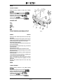
General
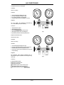
Tyres of the correct type, dimensions and a t the correct cold inflation pressures are an integral part of the
vehicle's design. Regular maintenance of tyres is an essential contribution to road safety and correctly
inflated tyres in good condition will assist in retaining optimum road-holding, steering and braking qualities.
Tyres of the same type and size have widely varying characteristics depending upon manufacturer. It is
strongly recommended that only tyres of the same make and type are fitted to all wheels.
The radial ply tyres specified are designed t o meet the high speed performance of which this car is capable.
Pressure
The tyre inflation pressures specified provide optimum ride and handling characteristics for all normal
conditions.
Tyre pressures should be checked and, if necessary, adjusted weekly with the tyres- cold i.e. not
immediately following use as pressure increases with temperature due t o road friction. 'Bleeding' a warm
tyre to the recommended pressure will result in under-inflation which can be both dangerous and
depreciate tyre life. Pressure loss with time is normal, but a thorough investigation should be performed if
a pressure loss in excess of 2 Ibflin2 (0.14 kgf/cm2, 14kPa, 014 bar) is encountered during a period of one
week or less.
It is an offence in the UK t o use a vehicle on public roads with tyres improperly inflated. Furthermore,
incorrect inflation accelerates wear and causes excessive heating which can result in tyre failure due t o
blow out.
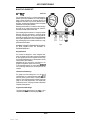
CAUTION: When inflating a tyre. it is important to ensure that a pressure of 40 lbflin2 (2.8 kgf/cm2,
310kPa. 3.1 bar) is not exceeded otherwise serious tyre damage may result.
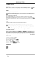
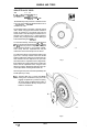
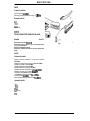
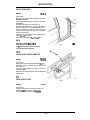
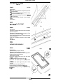
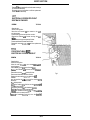
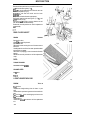
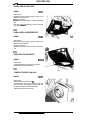
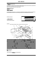
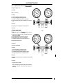
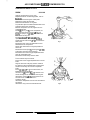
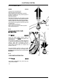
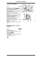
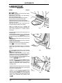
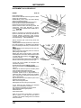
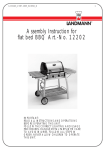
Wear
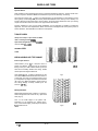
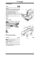
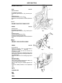
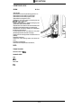
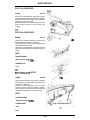
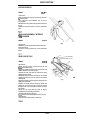
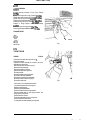
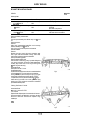
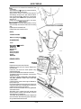
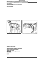
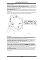
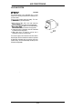
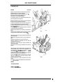
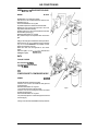
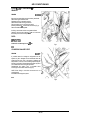
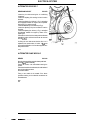
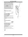
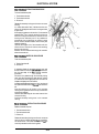
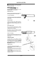
All tyres fitted as standard have a tread wear indicator (Fig. 1) moulded into their tread pattern t o provide
indication when the tread depth remaining is 1.6 mm (0.063in). Each indicator appears on the tread
surface as bars which connect the tread pattern across the full width of the tyre.
It is illegal in the UK and certain other countries t o continue using tyres after the tread has worn t o less than
1m m (0.039 in) over three quarters of the tread width around the entire circumference of the tyre.
Fig. 1
Issue 2
74-07
WHEELS AND TYRES
The properties of many tyres alter progressively with wear. In particular, ' w e t grip' and aquaplaning
resistance properties are graduallv, b u t substantially, reduced. Extra care and speed restriction should
therefore be exercised o n w e t roads as t h e effective tread depth diminishes.
When replacement of tyres is necessary it is preferable t o fit a complete vehicle set. Should either front or
rear tyres only, s h o w excessive wear, n e w tyres m u s t be fitte-d t o replace w o r n ones. Under n o
circumstances interchange tyres from side t o side, front t o rear or vice versa as individual tyre wear
produces unique characteristics depending upon their position. If t h e position is changed after wear has
occurred, t h e performance of t h e tyre will b e adversely affected.
Damage
Excessive localised distortion, sometimes caused by severe contact with kerbs or stones can cause t h e
tyre casing t o fracture and m a y lead t o premature t y r e failure. Tyres should, therefore, be periodically
examined and any tyre having distortion, cracks 'andlor c u t s should be replaced. In addition, all tread
imbedded objects, such as stones and glass, should be withdrawn and all contamination, i.e. oil and grease
removed using a suitable solvent.
CAUTION:
Paraffin (kerosene) m u s t n o t b e used as a cleansing agent on tyres.
Heat
Tyres should n o t be subjected t o excessive heat such as t h a t inherent of paint dryinglbaking ovens. It is
recommended therefore, t h a t all wheels b e removed or a t least t h e tyres be relieved of vehicle body
weight.
Repairs
It is recommended t h a t damaged tyres are renewed and n o t repaired in v i e w o f t h e high performance
capability of t h e vehicle.
Valves
When a n e w tubeless t y r e is fitted, t h e valve should be renewed.
Tyre Use After Vehicle Storage
After a long period o f vehicle standing, tyres m a y become locally distorted with a flat area. This will cause
an uneven ride f o r a f e w miles until t h e t y r p s have warmed up and t h e 'flat' rounds off.
lssue 2
74-08
WHEELS AND TYRES
'WINTER (SNOW) TYRES
The tyres fitted as original equipment are designed with a rubber mixture, tread pattern and width specially
suited for high speeds in normal road conditions, but they are less suitable for winter conditions. The use
of winter tyres will considerably improve the vehicle's handling.
Winter tyres must be used in vehicle sets, i.e. fitted on all four wheels. When fitted with winter tread tyres,
the vehicle should not be driven a t speeds in excess of the tyre speed category symbol as moulded on the
tyre.
SNOW CHAINS
Snow chains may be fitted to rear wheels only.
Remove the snow chains immediately upon the road being clear of snow.
Maximum speed with snow chains fitted - 30mph (48krn/h).
Tyres may be fitted with studs provided maximum speed does not exceed 90mph ( 145km/h). Studs must
be of the parallel type, 1 Omm long, 8mm diameter single flange; the use of studs is n-otpermitted in certain
countries, check local legislation.
Snow chains must only be used with the recommended winter tyres.
USA GRADINGS
The following information relates t o the tyre grading system developed by the national Highway Traffic
Safety Administration which grades tyres by tread wear, traction and temperature performance.
Treadwear
The treadwear grade is a comparative rating based on the wear rate of the tyre when tested under
controlled conditions on a specified government test course. For example, a tyre graded 150 would wear
one and a half times less on the government course than a tyre graded 100. The relative performance of
the tyres depends upon the actual conditions of their use and may depart significantly from normal due to
variations in driving habits, service practices and differences in road characteristics and climate.
Traction
- A, B, C
The tractions grades, from highest t o lowest, are A, B and C and they represent the tyres ability t o stop in
wet conditions measured on specified government test surfaces of asphalt and concrete.
WARNING:
THE TRACTION GRADE IS BASED ON BRAKING (STRAIGHT AHEAD) TRACTION TESTS
AND DOES NOT INCLUDE CORNERING (TURNING) TRACTION.
Temperature
- A, B, C
The temperature grades are A (the highest), B and C, and they represent the tyre's resistance t o the
generation of wear and its ability to dissipate heat when tested under controlled conditions on a specified
indoor laboratory test wheel. Sustained high temperature can cause the material of the tyre t o degenerate
and reduce tyre life, and excessive temperature can lead t o sudden tyre failure. Grade C corresponds to a
level of performance which all passenger cartyres must meet under Federal Motor Vehicle Safety Standard
No.109. Grades B and A represent higher levels of performance on the laboratory test wheel than the
minimum required by law.
WARNING:
Issue 2
THE TEMPERATURE GRADE IS ESTABLISHED FOR A TYRE THAT IS PROPERLY INFLATED
AND NOT OVERLOADED. EXCESSIVE SPEED, UNDERINFLATION, OR EXCESSIVE
LOADING, WHETHER SEPARATELY OR IN COMBINATION. CAN CAUSE HEAT BUILD UP
AND POSSIBLE TYRE FAILURE.
74-09
WHEELS AND TYRES
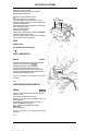
THE TD TYRE (where fitted)
74.00.00
DESCRlPTlON
The TD tyre offers the benefits of the radial assembly with the added safety and security of limited run-on
capability in the event of a deflation.
This can assist in the control of the vehicle to the nearest point where the wheel can be fitted in safety.
As an essential preliminary a new international standard of rim dimensions has been developed and
adopted by the European r y r e and Rim Technical Organisation ISTRTO). The rim sizes covered are 290,
31 5, 340, 365, 390,415mm diameter rims incorporating the Denloc groove allowing fitment of TD tyres.
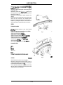
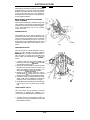
How it works
The TD wheel incorporates t w o grooves running circumferentially around the bead seats. The tyres have
specially extended bead toes which fit into these grooves. In the event of deflation, the reinforced bead
toes are held firmly in place by these grooves, thereby helping t o prevent the tyre from leaving the rim.
Both tyre and road wheel are made t o metric dimensions, in section width and wheel diameter. This is a
safety precaution to prevent the fitting of a conventional tyre t o the TD wheel and conversely of a TD tyre
t o a conventional wheel.
It should be noted that a TD tyre cannot be fitted to a normal wheel.
In a conventional radial tyre, the bead is designed to fit inside a vertical rim flange; the casing cords are
forced t o curve outwards above the flange before curving inwards again, thus forming an unnatural 'S'
shape. The secret of the TD principle. lies in both the unique radial construction and the rim contour which
allow the casing cords t o follow a natural 'C' shaped flexing curve. The rim flange is inclined outwards at
an angle parallel t o the natural line of the casing cords.
The advantages of the new TD tyres stem from their unique construction which distributes the stresses
evenly around the casing. The natural flexing curve permits the use of low aspect ratios without the usual
penalty of ride harshness.
The TD Tyres are manufactured t o the very high quality standards expected from all tyres and give the
following benefits:
Superb grip and performance
The very wide and distinctive tread patterns put a large area of rubber on the road for maximum grip.
Because of the unique construction, a very bold tread pattern with wide channels can be used without
causing rapid and uneven wear often associated with this type of pattern. Water clearance is excellent,
giving safe, sure grip in the wet.
Precise handling
The whole TD range with its low, wide profile gives improved stability and precise steering control.
Even Wear
The equalized stresses resulting from the natural flexing curve, allied t o the TD low profile casing, result
in remarkably even tread wear giving high mileage.
LOW rolling resistance and fuel economy
Extensive research has proved that the combination of the TD construction with its low aspect ratio on the
special rim, provides the optimum in rolling resistance, a vital factor in fuel economy.
74-10
Issue 2
WHEELS AND TYRES
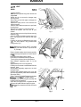
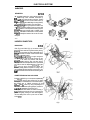
FITTING AND REMOVAL
General Notes
The TD is fitted and removed in the conventional w a y using the standard fitting machinery. The following
procedures should be used as a guide only. TD tyres must be fitted t o the appropriate size of TO rim.
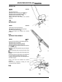
Removal
Deflate the tyre by removing the valve core.
Unseat, in turn, both tyre beads with a pneumatic unseating tool fitted with a broad blade. Ensure that the
edge of the blade is free from any rough edges.
Keep the blade close t o the wheel flange.
Apply a suitable lubrication t o the rim flanges and tyre bead area on both sides of the assembly.
Clamp the wheel t o the fitting machine and roll off the tyre beads in turn, following the machine
manufacturer's operating instructions. Take care not t o damage the tyre bead location 'toe' during this
process.
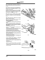
Fitting
Confirm that a suitable valve and core are correctly fitted t o the wheel rim.
Apply a suitable lubricant t o both bead and flange areas of the wheel, and both beads of the tyre.
Clamp the wheel t o the fitting machine and roll on each bead in turn, following the machine manufacturer's
operating instructions. Take care not t o damage the tyre bead location 'toe' during this process.
The TD tyre can only be fitted tubeless. No suitable design of tube is available or foreseen.
As with other modern rim designs incorporating bead retention safety features (humps, for example), it is
strongly recommended that a fitting machine is used for all fitting and removal. Use of hand levers for
removal is NOT recommended.
Unclamp the wheel and inflate the tyre t o 5 0 Ibf/inz (3.5 bar; 350kPa), ensuring that the beads remain
parallel to the rim groove. Should difficulty be experienced in securing location of the beads, remove the
valve core. Re-inflate the tyre, replacing the valve core when the beads of the tyre have located against the
wheel flanges. Check this by confirming that the tyre fitting line is concentric with t h e wheel flange.
Finally, reset the tyre pressure t o the recommended specification and remove any excess tyre.lubricant.
TORQUE FIGURES
Screw clamp to spare wheel 13-16Nm
Jack to mounting bracket 7- 14Nm
Spare wheel fixing bracket to body 22-28Nm
Valve to wheel 3.5-4.5Nm
Wheel nut to wheel stud (steel wheel) 65-85Nm
Wheel nut to wheel stud (all0y wheel) 88- 102 Nm
SPANNER SIZES
13mm
22mm
2000c
~
74-1 1
WHEELS AND TYRES
WHEELS
91 MY Standard Fit and Options
STEEL WHEEL
Size
Tyre Type/Size
7“ x 15”
Pirelli 225/65 VR 15
(225/65 R 15 99 V)
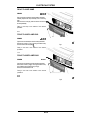
The 91 MY steel wheel is manufactured by Dunlop and incorporates a one piece wheel trim. The wheel is
held on w i t h wheel nuts and the wheel trim clips over the top. This differs from the 90MY steel wheel
manufactured by Michelin, which has the wheel trim held on by the wheel nuts and is of a different style.
The steel wheel is standard fit for the basic model XJ6 for all markets except USA.
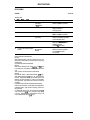
The wheel trim can be removed using the screwdriver provided in the vehicle toolbox as a lever, or similar
instrument. To refit the wheel trim, position the wheel trim on the wheel w i t h the location peg on the back
of the wheel trim inserted into the hole adjacent t o the tyre valve. Push the wheel trim firmly into position.
TEARDROP ALLOY WHEEL
Size
Tyre Type/Size
7” x 15”
Pirelli 225/65 VR 15
(225/65 R 15 99 V)
Pirelli 205/70 VR 15 - USA
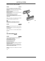
The Teardrop alloy wheel is standard fit f o r t h e XJ6-Sovereign in all markets, and an optional fit f o r t h e XJ6
in all markets except North America. The alloy wheel is standard fit for the basic XJ6 in the USA.
There are t w o types of wheel n u t cover for the Teardrop alloy style wheels, a perforated wheel nut cover
and a flush wheel nut cover. The wheel nut cover can be removed using the screwdriver provided in the
vehicle toolbox, or similar instrument. To refit the perforated style wheelnut cover, align the holes with the
wheel nuts, then push the cover firmly into position o n the wheel. To refit the flush style wheel nut cover,
push the cover firmly into position on the wheel.
The cast alloy road wheels are covered with a protective coating. To prevent corrosion, it is essential that
this coating is not damaged. To clean the wheels use warm soapy water; stubborn stains can be removed
using a soft brush or by using a proprietary alloy wheel cleaner.
When removing or fitting tyres, only equipment utilizing spigot or stud hole clamping must be used. The
equipment must not have any moving parts which contact the wheel, and tyre levers must not be used.
TEARDROP ALLOY WHEEL (TD TYPE)
Size
Tyre TypelSire
189mm x 390mm
Dunlop TD SP Super Sport D7, -220/65
VR 390 TD or
Michelin TDXV,220/65 VR 390
The TD Teardrop Alloy wheel is an optional item after 91MY for all models and markets except North
America.
Both tyre and road wheel are made t o metric dimensions, in section width and wheel diameter. This is a
safety precaution t o prevent the fitting of a conventional tyre t o the TD road wheel and conversely of a TD
tyre t o a conventional wheel.
It should be noted that a TD tyre cannot be fitted t o a normal wheel or a normal tyre t o a TD wheel.
Issue
2
74-1 2
WHEELS AND TYRES
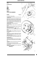
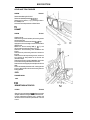
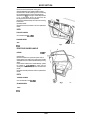
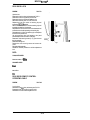
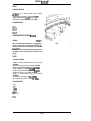
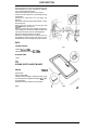
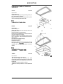
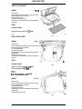
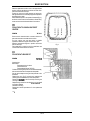
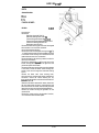
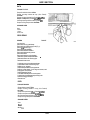
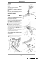
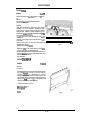
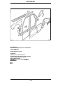
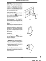
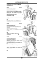
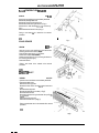
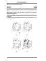
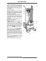
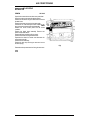
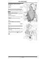
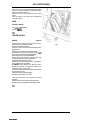
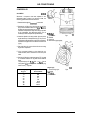
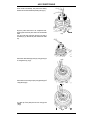
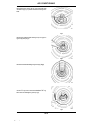
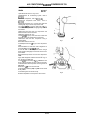
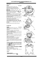
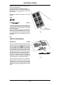
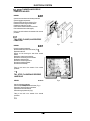
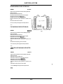
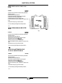
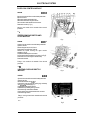
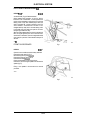
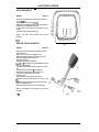
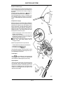
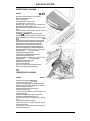
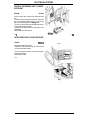
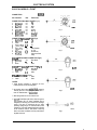
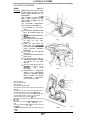
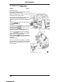
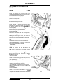
ROULETTE ALLOY WHEEL
Size
Tyre Type/Size
7" x 15"
Pirelli 225/65 VR 15
(225/65 R 15 99 V)
Pirelli 205/70VR 15 - USA
The Roulette style alloy wheel is a standard fit item
for XJ6-Daimler and Vanden Plas derivations in all
markets from 91 MY.
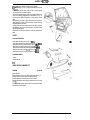
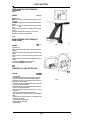
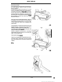
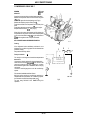
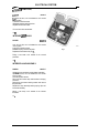
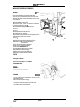
The Roulette wheel incorporates a diecast hubcap
with a rubber O-ring type seal round the outside to
ensure an optimum fit. The hubcap clips into the
wheel recess on one side using the hooks shown on
the back of the hubcap in Fig. 1, and is locked into
position using a bright chrome finished Allen type
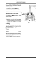
socket head locking screw (1 Fig.2).
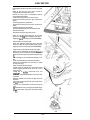
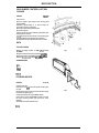
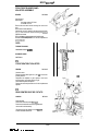
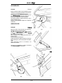
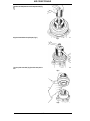
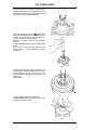
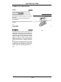
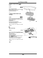
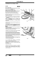
To remove the hubcap, unscrew the captivated bolt
(1 Fig. 2) securing the diecast hubcap (2 Fig. 2) using
the 6mm Allen key which is clipped t o the spare
wheel mounting bracket in the luggage compartment. Firmly hold the captivated bolt and pull
outwards to remove the hubcap from the wheel.
To replace the hubcap, ensure that the rubber O-ring
type seal is correctly located around the diecast
hubcap. Position the hubcap on the wheel with the
hook located in the slots adjacent to the tyre valve
and ensure that the captivated screw is aligned with
the threaded hole. Push the hubcap into position and
secure with the captivated screw, using the 6mm
Allen key to tighten. Replace the Allen key in the clip
on the spare wheel mounting bracket after use.
Fig 1
The locking screw is part of the hubcap assembly and
is held captive by a circlip.
k:
The
6mrn Allen key t o remove the hubcap
locking screw is attached to the jack in the
luggage compartment by means of a spring
clip. If the vehicle is supplied with a toolkit, it
is recommended that the key be kept in the
toolkit for convenience.
Fig 2
I
Issue 2
74-1 3
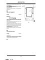
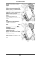
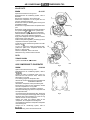
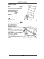
WHEELS AND TYRES
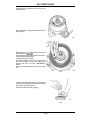
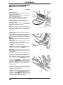
Replacement hubcaps are supplied without the
centre badge. Two different types of centre badge
are available (fig. 1 ) and must be correctly aligned
before push fitting into the centre of the hubcap.
The cast alloy road wheels are covered with a
protective coating. To prevent corrosion it is
essential that this coating is not damaged. To clean
the wheels use warm soapy water, stubborn stains
can be removed using a soft brush or by using a
proprietary alloy wheel cleaner.
When removing or fitting tyres, only equipment
utilizing spigot or stud hole clamping must be used.
The equipment must not have any moving parts
which contact the wheel, and tyre levers must not be
used.
Fig 1
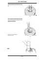
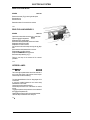
LATTICE (SPORTS)ALLOY WHEEL
Size
Tyre TypelSire
Rl
8” x 16”
Pirelli 225/55ZR 16 P600
JZ-OIL
The Lattice (Sports) wheel is available from 91 MY as
part of the Sports suspension package, it is an option
for all models and markets except North America. It is
a forged wheel with lattice design fitted with the
Pirelli 225/55ZR 16 P600 8” x 16“ tyre.
When changing the sports road wheels, the centre
badge must be transferred t o the replacement wheel.
After removing the road wheel, carefully remove the
badge and press fit to the replacement wheel.
74-14
Issue 2
WHEELS AND TYRES
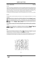
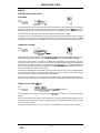
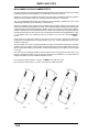
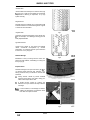
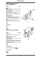
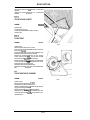
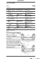
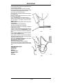
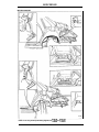
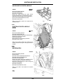
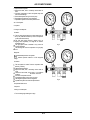
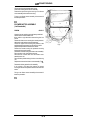
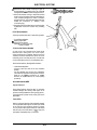
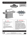
MISALIGNMENT AND ROAD CAMBER EFFECTS
It is important that correct wheel alignment be maintained. Misalignment causes tyre tread t o be scrubbed
off laterally because the natural direction of the wheel differs from that of the car.
A sharp ’fin’ protrusion on the edge of each pattern rib is a sure sign of misalignment and it is possible t o
determine from the position of the ‘fins’ whether the wheels are toeing in or toeing out.
‘Fins’ on the inside edges of the pattern ribs, particularly on the nearside tyre, indicate toe-in. ’Fins’ on the
outside edges, particularly on the offside tyre, indicate toe-out.
With minor misalignment, the evidence is less noticeable and sharp pattern edges may be caused by road
camber even when the wheel alignment is correct. In such cases it is better to make sure by checking with
an alignment gauge. Road camber affects the direction of the car by imposing a side thrust and, if left t o
follow it’s natural course, the car will drift towards it‘s nearside. This is instinctively corrected by a steering
towards the road centre and, as a result, the car runs crabwise as illustrated in an exaggerated form in (Fig.
1). The diagram shows why nearside tyres are very sensitive to too much toe-in and offside tyres t o
toe-out.
It also shows why sharp ’fins’ appear on one tyre but not on the other, and why the direction of
misalignment can be determ-ined by noting the position of the ’fins’. Severe misalignment produces clear
evidence on both tyres.
The front wheels on a moving car should be parallel. Tyre wear can be affected noticeably by quite small
variations from this condition. It will be noted from the diagram that even with parallel wheels, the car is
still out of line with its direction of movement, but there is less tendency for the wear to be concentrated
on one tyre.
The near front tyre sometimes persists in wearing faster and more unevenly than the other tyres, even
when the mechanical condition of the car and tyre maintenance are satisfactory. The more severe the
average road camber, the more marked this tendency will be.
Fig. 2 shows the wheels ’toed-out‘ in motion. The RH front tyre will wear faster.
Fig. 3 shows the wheels ‘toed-in’ in motion. The LH front tyre will wear faster.
Fig 1
Issue 2
Fig 2
74-1 5
Fig 3
WHEELS AND TYRES
ALIGNMENT PRECAUTIONS
Wheels and tyres vary laterally within their manufacturing tolerances, or as a result of service, and
alignment figures obtained without moving the car are unreliable. The following precautions should,
therefore, be observed:
1.
The car should have come t o rest from a forward movement. This ensures, as far as possible, that the
wheels are in natural running positions.
2.
It is preferable for alignment t o be checked with the car laden.
3. With a conventional base bar tyre alignment gauge, measurements should be taken in front of and
behind the wheel centres at the same position on the tyre and rim flanges. This is achieved by marking
the tyres where the first reading is taken and moving the car forwards approximately half a road wheel
revolution before taking the second reading at the same points. With an optical gauge, t w o or three
readings should be taken with the car moved forwards t o different positions - 1 80° road wheel turn
for t w o readings and 1 20° for three readings. An average figure should then be calculated.
TYRE AND WHEEL BALANCE
Static Balance
For smooth riding, precise steering and the avoidance of high speed 'tramp' or 'wheel hop', all tyres are
balance checked t o predetermined limits. To ensure the best degree of tyre balance, the covers are marked
with white spots on one bead and these indicate the highest part of the cover.
Some tyres are slightly outside standard balance limits and are corrected before issue by attaching special
patches t o the inside covers a t the crown. The patches contain no fabric and do not affect the local
stiffness of the tyre and should not be mistaken for repair patches. They are embossed 'Balance
Adjustment Rubber'.
The original degree of balance is not necessarily maintained and it may be affected by uneven tread wear,
cover and tube repair, tyre removal or refitting, or by wheel damage or eccentricity. The car may also
become sensitive t o unbalance due t o normal wear of moving parts. If roughness or high speed steering
troubles develop and mechanical investigation fails t o disclose a possible cause, wheel and tyre balance
should be suspected.
WARNING:
IF BALANCING EQUIPMENT IS USED TO DYNAMICALLY BALANCE THE ROAD WHEELS,
ALWAYS JACK BOTH REAR WHEEL§ OFF THE GROUND WHEN REAR WHEEL
BALANCING, OTHERWISE DAMAGE MAY BE CAUSED TO THE DIFFERENTIAL. THIS IS
DOUBLY IMPORTANT IN THE CASE OF CARS FITTED WITH A 'POWR-LOK' DIFFERENTIAL,
AS IN ADDITION TO POSSIBLE DAMAGE TO THE DIFFERENTIAL, THE CAR MAY DRIVE
ITSELF OFF THE JACK OR STAND.
74-1 6
Issue 2
WHEELS AND TYRES
Dynamic Balance
Static unbalance can be measured when the tyre and wheel assembly is stationary. There is another form
known as dynamic unbalance which can be detected only when the assembly is revolving.
There may be no heavy spot, i.e. there is no natural tendency for the assembly t o rotate about its centre
due t o gravity, but the weight may be unevenly distributed each side of-the centre tyre line. Laterally, the
eccentric wheels give the same effect. During rotation, the offset weight distribution sets up a rotating
couple which tends t o steer the wheel t o the right and left alternatively.
Dynamic unbalance of the tyre and wheel assemblies can be measured on suitable tyre balancing
equipment, and corrections implemented. Where it is clear that a damaged wheel is the primary cause of
severe unbalance, it is advisable for the wheel t o be replaced.
TORQUE FIGURES
Clamp screw clamp to spare wheel 13-16Nm
Jack to mounting bracket 7-14Nm
Spare wheel fixing bracket t o body 22-28Nm
Valve to wheel 3.5-4.5Nm
SPANNER
SIZES
13mm
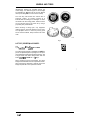
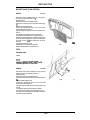
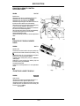
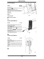
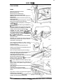
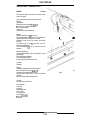
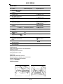
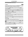
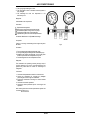
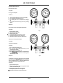
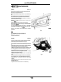
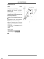
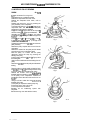
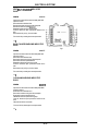
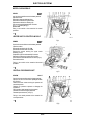
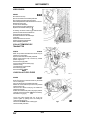
IRREGULAR WEAR AND TYRE DAMAGE
Incorrect Tyre Pressure
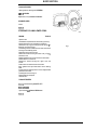
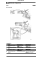
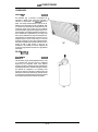
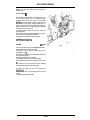
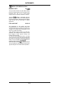
Under-inflation (A Fig. 1) is a frequent cause of
severe tyre damage, resulting from the excessive
flexing of the tyre. Under inflation builds up internal
heat which eventually weakens the casing. It also
causes rapid and irregular tread wear.
Over-inflation (C Fig. 1) leads t o shortened tyre life
with tread wear concentrated on the centre section in
contact with the road. The cushioning effect of the
tyre is impaired, resulting in a hard and uncomfortable
ride. The tyre is also susceptible t o impact fracture
and casing damage. Correctly inflated tyres are
shown in ( 6 Fig. 1).
a
b
C
JUE.021
Fig 1
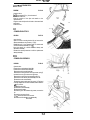
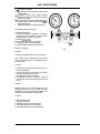
Misalignment Wear
Rasped and feathered tread condition is caused by
wheel misalignment and results in very rapid tread
wear (Fig. 2).
'Fins' on the inside edges of the pattern ribs,
Particularly on the nearside tyre, indicate toe-in.
'Fins' on the outside edges, particularly on the offside
W e , indicate toe-out.
Issue 2
74-1 7
JH 8 - 0 2 6
Fig 2
WHEELS AND TYRES
Camber Wear
One shoulder more severely worn than the other (Fig.
1). This type of wear is accentuated by mechanical
irregularities of steering or suspension, or by high
speed cornering.
Neglected Cut
Damage through accidental cuts or penetrations will
extend in use due t o continued flexing and/or ingress
of moisture and road matter.
J M 8.022
Irregular Wear
Fig I
Caused by mechanical irregularity of the vehicle (Fig.
2 ) as, for example, worn bearings, steering joints or
badly adjusted brakes.
Age Deterioration
Cracking and crazing of the tread and sidewall
rubber, sometimes accompanied by carcase
deformation. A n indication that the tyres have been
in service for a very long time.
Deflation Damage
JMB-On
Fig 2
Breakdown of the tyre casing structure which can
arise from under-inflation, overloading or running on a
flat tyre (Fig 3).
Impact Fracture
Resultant damage from impact fractures (Fig. 4) is
not always visible externally and, therefore, as a
safety precaution the tyre should be removed and
examined.
(a)
Casing fracture caused by severe localised
impact through driving over kerbs, hitting potholes and/or objects in the road.
JME.073
(b) A double fracture caused by crushing the
sidewall of the tyre between an object and the
rim flange.
Note:
In both instances, such damage can lead t o
sudden and dangerous tyre deflation some
time after the impact occurred.
a
b
Fig 4
~.
Issue 2
74-1 8
WHEELS AND TYRES
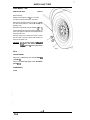
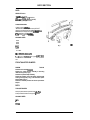
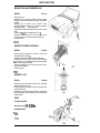
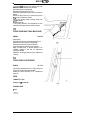
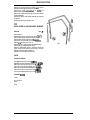
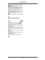
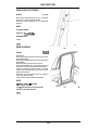
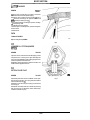
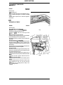
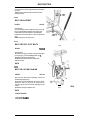
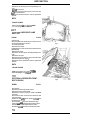
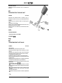
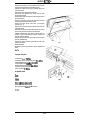
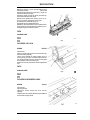
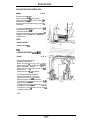
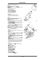
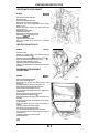
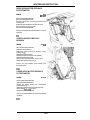
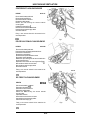
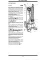
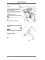
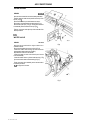
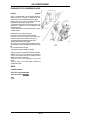
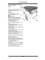
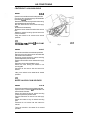
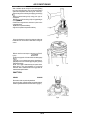
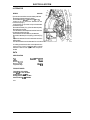
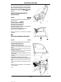
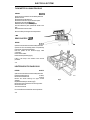
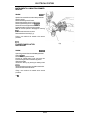
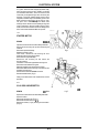
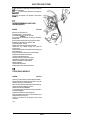
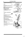
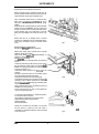
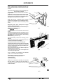
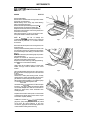
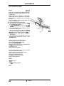
ROAD WHEEL
- ONE
REMOVE AND REFIT
74.20.0 1
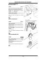
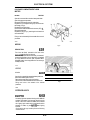
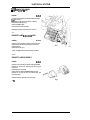
Remove hubcap.
Slacken the road wheel nuts % of a turn each.
Jack up the vehicle and place on one stand.
Remove one road wheel securing nut (1 Fig. 11, mark
the road wheel relative t o a stud and remove the
remaining nuts.
Remove the road wheel and tyre assembly (2 Fig. 1).
Lift the replacement road wheel and tyre assembly up
to the hub, align the wheel with the marked stud and
secure with the nuts.
Take the weight of the vehicle with a jack, remove
the axle stand, lower the vehicle and recheck the
torque of the wheel nuts.
CAUTION:
Do not exceed a torque of 85Nm I63
Ibf.ft) where steel wheels are fitted or
102Nm (75 Ibf .ft) where alloy wheels
are fitted.
Fig. 1
DATA
TORQUE FIGURES
Wheel nut to wheel stud (steel wheel) 65-85 Nm
(48-63Ibf. ft)
Wheel nut to wheel stud (alloy wheel) 88-102 Nm
(65-75 Ibf.ftl
SPANNER SIZES
22 mm
74-1 9
I
, Issue 2
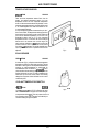
WHEELS AND TYRES
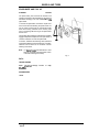
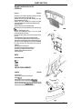
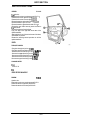
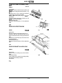
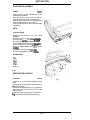
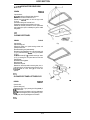
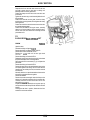
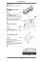
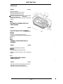
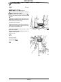
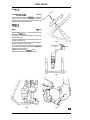
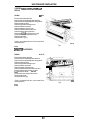
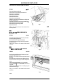
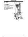
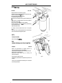
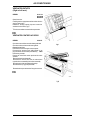
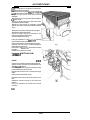
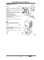
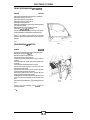
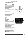
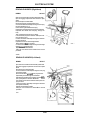
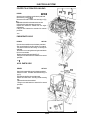
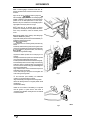
SPARE WHEEL AND TOOL KIT
74.20.04
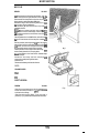
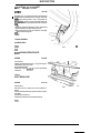
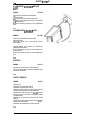
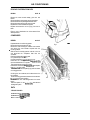
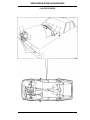
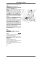
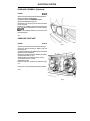
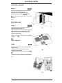
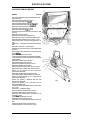
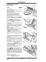
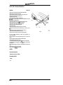
STOWAGE
The spare wheel, jack and tools are stowed in the
luggage compartment as illustrated (Fig. 1). The jack
and wheel changing tools are located behind ,the
spare wheel.
To remove the spare wheel, remove the carpet cover
and unscrew the bolt retaining the spare wheel. Lift
out the wheel. Ensure that the ratchet and wheel
brace are correctly positioned in the securing clips
prior t o positioning and securing of the spare wheel
and its cover.
The tool box (where fitted) is located a t the top ofthe
luggage Compartment adjacent t o the spare wheel. It
contains a selection of tools and spare bulbs.
To remove, hold down the retaining catch (below the
tool box) and slide the tool box rearwards. To replace,
slide the tool box back into its container until the
retaining catch locks.
Note:
4
For DaimlerNanden Plas derivatives a 6mm
Allen key is clipped t o the jack bracket, which
is used for removing the hubcap.
Fig. 1
DATA
TORQUE FIGURES
Spare wheel/tool
22-28Nm.
stowage
bracket
to
body
SPANNER SIZES
13mm
74-20
Issue 2
BODY SECTION
~~
CONTENTS
DESCRIPTION
OPERATION
A POST LOWER TRIM PAD ...................................
ASHTRAY ..........................................................
AUTOMATIC GEARBOX SELECTOR TRIM FINISHER
B-C POST CAPPING .............................................
B POST LOWER TRIM PAD...................................
B POST UPPER TRIM PAD....................................
BONNET ............................................................
BONNET HINGE (FEDERAL)..................................
BONNET HINGE (NON FEDERAL)...........................
BONNET HINGE VEHICLE SET (FEDERAL) ...............
BONNET HINGE VEHICLE SET (NON FEDERAL).......
BONNET GAS STRUT ..........................................
BONNET GAS STRUT-VEHICLE SET ......................
BONNET INSULATION PAD ..................................
BONNET LOCK ...................................................
BONNET SEALING RUBBER-REAR.........................
BONNET STRIKER ASSEMBLY ..............................
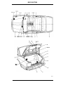
BOOT FLOOR CARPET.........................................
BOOT FRONT LINER............................................
BOOT LID ...........................................................
BOOT LID ADJUST ON STRIKER ...........................
BOOT LID GAS STRUT .........................................
BOOT LID HINGE - VEHICLE SET ...........................
BOOT LID LOCK BARREL.....................................
BOOT LID LOCK MECHANISM ..............................
BOOT LID LOCK STRIKER ....................................
BOOT LID SEAL ..................................................
BOOT LID STRUT PIVOT BOLTS...........................
BOOT LID SEAL TREAD PLATE.............................
BONNET LOCK CONTROL CABLE ..........................
BONNET LOCK CONTROL CABLE ASSEMBLYVEHICLE SET ......................................................
BONNET LOCK RELEASE HANDLE.........................
BOOT LOCK RELEASE TRIGGER HANDLE...............
BOOT LOCK FINISHER.........................................
BOOT REAR LINER ..............................................
BOOT SIDE LINER-LEFT HAND ..............................
BOOT SIDE LINER-RIGHT HAND............................
BOOT VENTILATOR OUTLET ................................
BUMPER FRONT .................................................
BUMPER FRONT ASSEMBLY ................................
BUMPER REAR-ASSEMBLY..................................
BUMPER REAR-ASSEMBLY ..................................
CANTRAIL CRASH ROLL......................................
CONSOLE ASHTRAY ...........................................
CONSOLE ASSEMBLY .........................................
CONSOLE FINISHER - AUTOMATIC .......................
CONSOLE FINISHER - MANUAL............................
CONSOLE GLOVEBOX .........................................
CONSOLE GLOVEBOX LID ....................................
DASH LINER DRIVERS SIDE ..................................
DASH LINER PASSENGERS SIDE ...........................
DOOR AIR VENT GROMMET .................................
ELECTRICALLY OPERATED FRONT SEAT ...............
ELECTRICALLY OPERATED FRONT SEAT BACK
FINISHER ...........................................................
ELECTRICALLY OPERATED FRONT SEAT CUSHION
ELECTRICALLY OPERATED FRONT SEAT-RUNNER
AND MOTOR ......................................................
MIRROR .............................................
BOARD..................................................
CENTRE VENEER PANEL..........................
RENEW ....................
RENEW ....................
RENEW ....................
RENEW ....................
RENEW ....................
RENEW ....................
RENEW ....................
RENEW ....................
RENEW ....................
RENEW ....................
RENEW ....................
RENEW ....................
R E N f W....................
RENEW ....................
RENEW ....................
RENEW ....................
RENEW ....................
RENEW ....................
RENEW ....................
RENEW ....................
ADJUST ...................
RENEW ....................
RENEW ....................
RENEW ....................
RENEW ....................
RENEW ....................
RENEW ....................
RENEW ....................
RENEW ....................
RENEW ....................
OPERATION
No
76.13.30
76.67.13
76.25.07
76.43.34
76.13.29
76.13.28
76.1 6.01
76.16.11
76.16.11
76.16.12
76.16.12
76.16.15
76.16.1 6
76.1 6.06
76.O 0.00
76.16.04
76.16.24
76.19.30
76.19.31
76.19.01
76.19.04
76.19.27
76.19.28
76.19.19
76.19.25
76.19.12
76.19.06
76.00.00
76.19.09
76.16.29
PAGE
No
76-79
76-93
76-93
76-80
76-80
76-80
76-24
76-29
76-28
76-30
76-28
76-26
76-26
76-14
76-25
76-25
76-25
76-68
76-68
76-63
76-62
76-64
76-67
76-66
76-64
76-66
76-63
76-64
76-67
76-26
RENEW ....................
RENEW ....................
RENEW ....................
RENEW ....................
RENEW ....................
RENEW ....................
RENEW ....................
RENEW ....................
RENEW ....................
OVERHAUL ..............
RENEW ....................
OVERHAUL ..............
RENEW ....................
RENEW ....................
RENEW ....................
RENEW ....................
RENEW ....................
RENEW ....................
RENEW ....................
RENEW ....................
RENEW ....................
RENEW ....................
RENEW ....................
76.16.35
76.16.30
76.19.1 5
76.43.31
76.19.22
76.19.22
76.19.23
80.15.66
76.22.08
76.22.09
76.22.15
76.22.18
76.13.10
76.67.18
76.25.01
76.25.19
76.25.19
76.25.16
76.25.18
76.46.11
76.46.15
80.00.00
76.70.10
76-27
76-27
76-65
76-65
76-67
76-68
76-69
76-66
76-1 5
76-1 5
76-47
76-47
76-81
76-81
76-81
76-82
76-83
76-82
76-82
76-83
76-83
76-83
76-70
RENEW ....................
RENEW ....................
76.70.09
76.70.11
76-71
76-69
RENEW ....................
RENEW ....................
RENEW ....................
RENEW ....................
76.70.08
76.10.52
76.46.01
76.47.06
76-70
76-52
76-84
76-86
0051G
Issue 2
76-01
BODY SECTION
CONTENTS
DESCRIPTION
OPERATION
OPERATION
No
PAGE
No
FASCIA CLOSING PANEL .DRIVERS SIDE ..............
FASCIA CLOSING PANEL .PASSENGERS SIDE .......
FRONT BUMPER CENTRE BLADE ..........................
FRONT BEAM.....................................................
FRONT BEAM COVER ..........................................
FRONT CROSSMEMBER.......................................
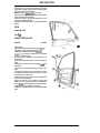
FRONT DOOR ARMREST ......................................
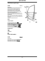
FRONT DOOR GLASS..........................................
FRONT DOOR GLASS CHANNEL RUBBER..............
FRONT DOOR GLASS FRAME...............................
FRONT DOOR HANDLE........................................
FRONT DOOR INSIDE HANDLE.............................
FRONT DOOR LOCK ............................................
FRONT DOOR LOCK STRIKER ...............................
FRONT DOOR OUTER HANDLE OPERATING ROD....
FRONT DOOR REMOTE CONTROL OPERATING
CABLE ...............................................................
FRONT DOOR SEAL.............................................
FRONT DOOR TRIM PAD VENEER PANEL...............
FRONT DOOR UPPER TRIM PAD...........................
FRONT DOOR LOWER TRIM PAD..........................
FRONT DOOR WAIST RAIL MOULDING .................
FRONT ENERGY ABSORBING STRUT .....................
FRONT FLOOR CARPET.......................................
FRONT QUARTER BUMPER ..................................
FRONT QUARTER BUMPER BLADE........................
FRONT QUARTER BUMPER LOCATING BRACKET...
FRONT QUARTER BUMPER MOUNTING RUBBER ....
FRONT SEAT......................................................
FRONT SEAT BELTS (91 MY)...............................
FRONT SEAT BACK FINISHER..............................
FRONT SEAT BELT ADJUSTER .............................
FRONT SEAT BELT BUCKLE UNIT.........................
FRONT SEAT BELT LEFT HAND............................
FRONT SEAT BELT RIGHT HAND..........................
FRONT SEAT CUSHION.......................................
FRONT SEAT-CUSHION COVER............................
FRONT SEAT CUSHION SUPPORT CENTRE............
FRONT SEAT HEADREST.....................................
FRONT SEAT HEAD REST-ELECTRICALLY
OPERATED SEAT ................................................
FRONT SEAT RUNNERS AND ADJUSTER
ASSEMBLY ........................................................
FUEL FILLER CAP RETENTION MAGNET
(91 MY1.............................................................
FUEL FILLER FLAP LATCH POST (91 MY)...............
GEARBOX SPORT MODE SWITCH FINISHER..........
GLOVE BOX .......................................................
GLOVEBOX LID ...................................................
GLOVEBOX LID LOCK ..........................................
GLOVEBOX LID VENEER PANEL............................
GLOVEBOX MIRROR ASSEMBLY ..........................
GUTTER FINISHER ..............................................
HANDBRAKE LEVER TRIM ....................................
HEADLAMP TRIM FINISHER .................................
HEADLINING REAR .FINISHER...............................
ILLUMINATED SUNVISOR ASSY ...........................
ILLUMINATED SUNVISOR MIRROR ASSY ..............
INDEX ...............................................................
INSTRUMENT PANEL'VENEER PANEL....................
INTERIOR MIRROR..............................................
RENEW ....................
RENEW ....................
RENEW ....................
RENEW ....................
RENEW ....................
RENEW ....................
RENEW ....................
RENEW ....................
RENEW ....................
RENEW ....................
RENEW ....................
RENEW ....................
RENEW ....................
RENEW ....................
ADJUST ...................
76.46.28
76.46.27
76.22.37
76.22.26
76.22.20
76.10.05
76.34.22
76.31.01
76.31.13
76.31.51
76.58.01
76.58.20
76.37.12
76.37.23
76.37.10
76-86
76-86
76-1 6
76-95
76-94
76-1 8
76-30
76-31
76-32
76-33
76-33
76-34
76-35
76-37
76-98
RENEW ....................
RENEW ....................
RENEW ....................
RENEW ....................
RENEW ....................
RENEW ....................
RENEW ....................
RENEW ....................
RENEW. ...................
RENEW ....................
RENEW ....................
RENEW ....................
RENEW ....................
RENEW ....................
RENEW ....................
RENEW ....................
RENEW ....................
RENEW ....................
RENEW ....................
RENEW ....................
RENEW ....................
RENEW ....................
RENEW ....................
76.37.67
76.40.01
76.47.11
76.34.02
76.34.03
76.43.04
76.22.31
76.49.02
76.22.16
76.22.73
76.22.20
76.22,19
76.70.01
76.73.00
76.70.03
76.73.1 2
76.73.02
76.73.10
76.73.21
76.70.02
76.70.02
76.70.19
76.70.30
76-26
76-38
76-36
76-38
76-36
76-37
76-17
76-72
76-21
76-23
76-22
76-22
76-72
76-1 16
76-72
76-76
76-73
76-73
76-74
76-74
76-74
76-75
76-75
RENEW ....................
76.70.14
76-71
RENEW ....................
76.70.24
76-76
RENEW ....................
RENEW ....................
RENEW ....................
RENEW ....................
RENEW ....................
RENEW ....................
RENEW ....................
RENEW ....................
RENEW ....................
RENEW ....................
RENEW ....................
RENEW ....................
RENEW ....................
RENEW ....................
ILLUSTRATED...........
RENEW ....................
RENEW ....................
76.10.27
76.10.28
76.25.09
76.52.03
76.52.02
76.52.08
76.47.21
76.52.05
76.43.11
76.13.63
76.40.01
76.64.1 2
76.10.48
76.10.50
76.00.00
76.47.24
76.10.51
76-1 16
76-1 16
76-97
76-87
76-87
76-88
76-88
76-89
76-53
76-89
76-24
76-89
76-93
76-93
76-06
76-99
76-90
0051G
76-02
Issue 2
....
-.. .............
.........
.- ......
.
BODY SECTION
CONTENTS
0PERAT10N
DESCRlPTlON
.
LAP BELT INERTIA REEL......................................
LOWER DOOR TRIM FRONT.................................
LOWER DOOR TRIM REAR...................................
NUMBER PLATE TRIM .........................................
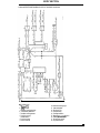
PASSIVE ECU.....................................................
PASSIVE RESTRAINT..........................................
PASSIVE RESTRAINT..........................................
PASSIVE RESTRAINT..........................................
PASSIVE RESTRAINT GUIDE RAIL.........................
PASSIVE RESTRAINT ECU...................................
PASSIVE RESTRAINT ECU...................................
PASSIVE RESTRAINT INERTIA REEL......................
PASSIVE RESTRAINT MOTOR/DRIVE AND INERTIA
REEL ASSEMBLIES..............................................
PASSIVE RESTRAINT SYSTEM (USA ONLY) ...........
PASSIVE RESTRAINT WARNING CIRCUIT..............
PETROL FILLER FLAP...........................................
RADIATOR GRILLE SURROUND............................
RADIATOR GRILLE - VEHICLE SET ........................
RADIO CONSOLE................................................
REAR BEAM.......................................................
REAR BEAM COVER............................................
REAR BUMPER CENTRE BLADE.............................
REAR BUMPER CENTRE BLADE TRIM FINISHER ......
REAR CENTRE SEAT BELT STATIC ........................
REAR DOOR ARMREST ........................................
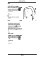
REAR DOOR GLASS............................................
REAR DOOR GLASS CHANNEL RUBBER.................
REAR DOOR GLASS FRAME.................................
REAR DOOR HANDLE..........................................
REAR DOOR INSIDE HANDLE...............................
REAR DOOR LOCK ..............................................
REAR DOOR LOCK STRIKER.................................
REAR DOOR LOWER TRIM PAD ............................
REAR DOOR OUTER HANDLE OPERATING ROD ......
REAR DOOR REMOTE CONTROL OPERATING
CABLE ...............................................................
REAR DOOR SEAL...............................................
REAR DOOR TRIM PAD VENEER PANEL.................
REAR DOOR UPPER TRIM PAD.............................
REAR DOOR WAIST RAIL MOULDING ....................
REAR FLOOR CARPET .........................................
REAR LAMP ASSEMBLY INTERIOR TRIM FINISHER.
REAR PARCEL TRAY ...........................................
REAR QUARTER BUMPER ....................................
REAR QUARTER BUMPER BLADE..........................
REAR QUARTER BUMPER LOCATING BRACKET.....
REAR QUARTER BUMPER MOUNTING RUBBER......
REAR QUARTER TRIM PAD..................................
', REAR QUARTER UPPER TRIM PAD LEFT HAND ......
REAR QUARTER UPPER TRIM PAD RIGHT HAND ....
'REAR SEAT ARMREST .........................................
''W%R SEAT CUSHION.........................................
I'
REAR SEAT SQUAB............................................
PEAR SHELF FINISHER........................................
'REAR SIDE SEAT BELT........................................
SILL TREAD PLATE - FRONT.................................
TREAD PLATE - REAR...................................
1
No
PAGE
No
RENEW ....................
RENEW ....................
RENEW ....................
RENEW ....................
CONNECTORS ..........
FAULT DIAGNOSIS....
SERVICE CHECKS .....
WIRING DIAGRAM....
RENEW ....................
OPERATIONAL TEST .
LOGIC......................
RENEW ....................
76.73.22
76.34.03
76.34.06
76.43.22
76.73.00
76.73.00
76.73.00
76.73.00
76.73.33
76.73.00
76.73.00
76.73.23
76-1 15
76-53
76-53
76-53
76-1 11
76-102
76-1 12
76-109
76-1 14
76- 106
76-107
76-1 14
RENEW ....................
DESCRIPTION...........
WIRING DIAGRAM ....
RENEW ....................
RENEW ....................
RENEW ....................
RENEW ....................
RENEW ....................
RENEW ....................
RENEW ....................
RENEW ....................
RENEW ....................
RENEW ....................
RENEW ....................
RENEW ....................
RENEW ....................
RENEW ....................
RENEW ....................
RENEW ....................
RENEW ....................
RENEW ....................
ADJUST ...................
76.73.27
76.73.00
76.73.00
76.10.25
76.55.15
76.55.07
76.25.15
76.22.27
76.22.29
76.22.12
76.22.14
76.73.31
76.34.23
76.31.02
76.31.14
76.31.61
76.58.02
76.58.19
76.37.13
76.37.24
76.34.06
76.37.1 1
76-1 13
76-1 00
76-1 10
76-53
76-54
76-54
76-93
76-96
76-94
76-51
76-52
76-76
76-39
76-38
76-40
76-41
76-41
76-42
76-43
76-46
76-44
76-97
RENEW ....................
RENEW ....................
RENEW ....................
RENEW ....................
RENEW ....................
RENEW ....................
RENEW ....................
RENEW ....................
RENEW ....................
RENEW ....................
RENEW ....................
RENEW ....................
RENEW ....................
RENEW ....................
RENEW ....................
RENEW ....................
RENEW ....................
RENEW ....................
RENEW ....................
RENEW ....................
RENEW ....................
RENEW ....................
76.37.68
76.40.02
76.47.12
76.34.05
76.43.05
76.49.03
76.19.20
76.67.06
76.22.17
76.25.75
76.22.22
76.22.21
76.13.13
76.13.13
76.13.43
76.70.39
76.70.37
76.70.38
76.67.06
76.73.18
76.76.01
76.76.02
76-43
76-46
76-45
76-45
76-45
76-79
76-90
76-90
76-48
76-50
76-50
76-49
76-62
76-91
76-91
76-77
76-77
76-78
76-78
76-78
76-55
76-55
io51~
I
~
Issue 2
....
!
OPERATION
76-03
BODY SECTION
CONTENTS
DESCRIPTION
OPERATION
SLIDING ROOF ASSEMBLY ...................................
SLIDING ROOF FLANGE FINISHER.........................
SLIDING ROOF MOTOR DRIVE GEAR .....................
SLIDING ROOF PANEL.........................................
SLIDING ROOF PANEL LIFTING BLOCK ..................
SLIDING ROOF PANEL LIFTING BLOCK VEHICLE
SET ...................................................................
SLIDING ROOF PANEL SEAL.................................
SLIDING ROOF PANEL TRIM .................................
SLIDING ROOF PANEL WIND DEFLECTOR..............
SLIDING ROOF RACK..........................................
SLIDING ROOF RACK VEHICLE SET .......................
SLIDING ROOF WIND DEFLECTOR........................
STEERING COLUMN LOWER COWL.......................
STEERING COLUMN UPPER COWL........................
WEATHER STRIP ................................................
WEATHER STRIP CHANNEL.................................
WINDSCREEN GLASS .LOWER FINISHER..............
OPERATION
NO
NO
RENEW ....................
RENEW ....................
RENEW ....................
RENEW ....................
RENEW ....................
76.82.01
76.82.23
76.82.44
76.82.05
76.82.27
76-55
76-56
76-57
76-57
76-57
ADJUST ...................
RENEW ....................
RENEW ....................
ADJUST ...................
RENEW ....................
RENEW ....................
RENEW ....................
RENEW ....................
RENEW ....................
RENEW ....................
RENEW ....................
RENEW ....................
76.82.38
76.82.15
76.82.19
76.82.39
76.82.42
76.82.43
76.82.07
76.46.03
76.46.02
76.43.22
76.43.25
76.43.41
76-58
76-58
76-58
76-59
76-59
76-60
76-61
76-92
76-91
76-61
76-62
76-62
0051G
76-04
issue 2
PAGE
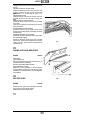
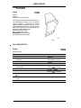
BODY SECTION
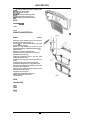
76-05
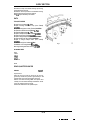
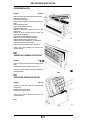
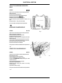
BODY SECTION
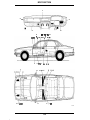
36 €t
18
21
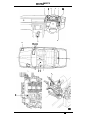
J76 574
76 -06
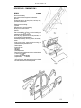
BODY SECTION
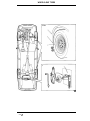
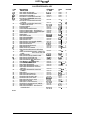
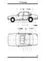
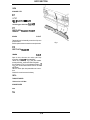
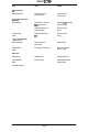
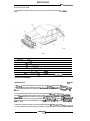
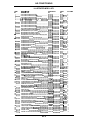
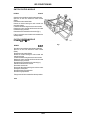
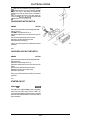
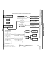
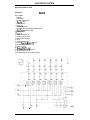
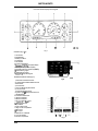
ILLUSTRATED INDEX- KEY
ITEM
No
1 ...........
2...........
3 ...........
4...........
5 ...........
6...........
7...........
8 ...........
9...........
10...........
1 1 ...........
12...........
13 ...........
14...........
15 ...........
16...........
17...........
IS ...........
19...........
20 ...........
21 ...........
22...........
23 ...........
24...........
25 ...........
26 ...........
27 ...........
28...........
29 ...........
30...........
31 ...........
DESCRIPTION
A POST LOWER TRIM PAD ................................
ASHTRAY ........................................................
AUTOMATIC GEARBOX SELECTOR TRIM
FINISHER
.....................................................
-~
B-C POST CAPPING..........................................
B POST LOWER TRIM PAD ................................
B POST UPPERTRIM PAD.................................
BONNET..........................................................
BONNET HINGE (FEDERAL) ..............................
BONNET HINGE (NON FEDERAL).......................
BONNET HINGEVEHICLESET (FEDERAL) ...........
BONNET HINGEVEHICLE SET (NON FEDERAL)...
BONNET GAS STRUT........................................
BONNET GAS STRUT-VEHICLE SET ..................
BONNET INSULATION PAD...............................
BONNET LOCK.................................................
BONNETSEALING RUBBER- REAR ...................
BONNETSTRIKER ASSEMBLY ...........................
BOOT FLOOR CARPET......................................
BOOT FRONT LINER .........................................
BOOT LID ........................................................
BOOT LID ADJUSTON STRIKER .........................
BOOT LID GAS STRUT......................................
BOOT LID HINGE-VEHICLE SET........................
BOOT LID LOCK BARREL..................................
BOOT LID LOCK MECHANISM...........................
BOOT LID LOCK STRIKER..................................
BOOT LID SEAL................................................
BOOT LID STRUT PIVOT BOLTS.........................
BOOT LID SEALTREAD PLATE...........................
BONNET LOCK CONTROLCABLE.......................
BONNET LOCK CONTROL CAB LE ASSEM 8 LY .
VEHICLE SET.................................................
BONNET LOCK RELEASE HANDLE .....................
BOOTLOCK RELEASETRIGGER HANDLE...........
BOOT LOCK FINISHER......................................
BOOT REAR LINER ...........................................
BOOTSIDE LINER-LEFT HAND.........................
BOOTSIDE LINER-RIGHT HAND ......................
BOOTVENTILATOR OUTLET..............................
BUMPER FRONT-ASSEMBLY............................
BUMPER FRONT-ASSEMBLY............................
BUMPER REAR-ASSEMBLY..............................
BUMPER REAR-ASSEMBLY..............................
CANTRAIL CRASH ROLL...................................
CONSOLEASHTRAY.........................................
CONSOLEASSEMBLY ......................................
CONSOLE FINISHER-AUTOMATIC ...................
CONSOLE FINISHER-MANUAL ........................
CONSOLE GLOVEBOX.......................................
CONSOLE GLOVEBOX LID.................................
~~~
32...........
33 ...........
34...........
35 ...........
36 ...........
37 ...........
38...........
39 ...........
39 ...........
40...........
40...........
41 ...........
42...........
43...........
44...........
45 ...........
46 ...........
47...........
~~
W32K
76-7
0 PERATIO N
No
76.13.30
.................
76.67.13.................
No
76.79. ....... 4
76-93........ 4
76.25.07.................
76.43.34
.................
76.13.29.................
76.13.28.................
76.16.01.................
76.16.11.................
76.16.11 .................
76.16.12.................
76.16.12
.................
76.16.15
.................
76.16.16........... ......
76.16.06.................
76.00.00.................
76.16.04.................
76.16.24.................
76.19.30.................
76.19.31.................
76.19.01.................
76.19.04
.................
76.19.27.................
76.19.28
.................
76.19.19
.................
76.19.25.................
76.19.12.................
76.19.06
.................
76.00.00.................
76.19.09
.................
76.16.29.................
76.93. .......
76.80. .......
76-80.........
76.80. .......
76-24........
76-29.........
76.28. .......
76-30........
76-28.......
76-26........
76.26. .......
76-14........
76-25........
76-25........
76.25. .......
76.68. .......
76-68........
76.63. .......
76.62. .......
76.64. .......
76.67. .......
76.66. .......
76.64. .......
76-66........
76-63........
76-64........
76.67. .......
76-26........
76.16.35.................
76.16.30
.................
76.19.15.................
76.43.31.................
76.19.22.................
76.19.22.................
76.19.23.................
76.15.66.................
76.22.08.................
76.22.09.................
76.22.15.................
76.22.18.................
76.13.10.................
76.67.18.................
76.25.01.................
76.25.19.................
76.25.19.................
76.25.16.................
76.25.18.................
76-27........
76-27........
76-65........
76-65........
76.67. .......
76-68........
76-69........
76-66........
76-15........
76-15........
76.47. .......
76-47........
76-81........
76-81........
76-81........
76-82........
76-83........
76-82-.......
76.82. .......
PAGE
VOLUME
4
4
4
4
4
4
4
4
4
4
4
4
4
4
4
4
4
4
4
4
4
4
4
4
4
4
4
4
4
4
4
4
4
4
4
4
4
4
4
4
4
4
4
4
4
4
4
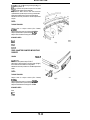
BODY SECTION
57
59
-
58
nu
on
49
48
68, 69, 70,71, 72 a 73
75
50
55
I
,
74
81, 82,
k Et 84
\
53. 91,,92B 93
76, 77
78
/
%
!
94/Et 95
52'86
87.
80
& 89
J76 575
76-8
B0DY S ECTlON
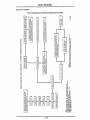
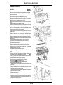
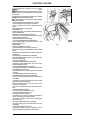
ILLUSTRATED INDEX- KEY
D ESCRl PTlON
ITEM
No
48 ........... DASH LINER DRIVERS SIDE ..............................
49 ........... DASH LINER PASSENGERS SIDE .......................
50 ........... DOOR AIRVENTGROMMET ..............................
51 ........... ELECTRICALLY OPERATED FRONT SEAT.............
52 ........... ELECTRICALLY OPERATED FRONT SEAT
BACK FINISHER............................................
53 ........... ELECTRICALLY OPERATED FRONT SEAT
CUSHION.....................................................
54 ........... ELECTRICALLYOPERATED FRONT SEATRUNNER AND MOTOR ..................................
55 ........... EXTERIOR MIRROR ..........................................
56 ........... FASCIA BOARD................................................
57 ........... FASCIA CENTRE VENEER PANEL........................
58 ........... FASCIA CLOSING PANEL- DRIVERS SIDE ..........
59 ........... FASCIA CLOSING PANEL- PASSENGERSSIDE...
60 ........... FRONT BUMPER CENTRE BLADE.......................
61 ........... FRONT BEAM ..................................................
62 ........... FRONT BEAM COVER .......................................
63 ........... FRONT CROSSMEMBER...................................
64 ........... FRONT DOOR ARMREST...................................
65 ........... FRONT DOOR GLASS .......................................
66 ........... FRONT DOOR GLASS CHANNEL RUBBER ..........
67 ........... FRONT DOOR GLASS FRAME............................
68 ........... FRONT DOOR HANDLE.....................................
69 ........... FRONT DOOR INSIDE HANDLE..........................
70 ........... FRONT DOOR LOCK .........................................
71 ........... FRONT DOOR LOCK STRIKER............................
72 ........... FRONT DOOR OUTER HANDLE OPERATING
ROD.............................................................
73 ........... FRONT DOOR REMOTE CONTROLOPERATING
CABLE .........................................................
74 ........... FRONT DOOR SEAL..........................................
75 ........... FRONT DOOR TRIM PAD VENEER PANEL...........
76.,. ........ FRONT DOOR UPPER TRIM PAD........................
77 ........... FRONT DOOR LOWER TRIM PAD.......................
78 ........... FRONT DOOR WAIST RAIL MOULDING..............
79 ........... FRONT ENERGYABSORBING STRUT.................
80 ........... FRONT FLOOR CARPET ....................................
81 ........... FRONT QUARTER BUMPER...............................
82 ........... FRONT QUARTER BUMPER BLADE....................
83 ........... FRONT QUARTER BUMPER LOCATING
BRACKET .....................................................
84 ........... FRONT QUARTER BUMPER MOUNTING
RUBBER.......................................................
85 ........... FRONT SEAT....................................................
86 ........... FRONT SEAT BACK FINISHER............................
87 ........... FRONT SEAT BELT ADJUSTER ...........................
88 ........... FRONTSEAT BELT BUCKLE UNIT.......................
89 ........... FRONTSEAT BELT LEFT HAND..........................
90 ............ FRONT SEAT BELT RIGHT HAND........................
91 ........... FRONT SEAT CUSHION.....................................
92 ........... FRONT SEAT-CUSHION COVER .......................
93 ........... FRONTSEAT CUSHION SUPPORT CENTRE.........
94 ........... FRONT SEAT HEADREST...................................
95 ........... FRONT SEAT HEAD REST- ELECTRICALLY
OPERATED SEAT...........................................
0032K
76-9
0 PERAT10N
No
76.46.11 .................
76.46.15 .................
76.00.00.................
76.70.1 0.................
PAGE
VOLUME
76-83.........
76-83.........
76-83.........
76-70.........
4
4
4
4
76.70.1 1.................
_
76-69_ .......
4
76.70.08.................
76.1 0.52.................
76.46.01.................
76.47.06.................
76.46.28.................
76.46.27 .................
76.22.37 .................
76.22.26 .................
76.22.28 .................
76.1 0.05................
76.34.22.................
76.31.01 .................
76.31.13 .................
76.31.51 .................
76.58.01 ................
76.58.20.................
76.37.12.................
76.37.23 .................
76.70 ........
76-52 .......
76-84 .......
76-86.......
76-86.........
76-86 .......
76-16 .......
76-95- .......
76-94 .....
76-18 .........
76-30- .......
76-31- .......
76-32- .......
76-33- .......
76-33 .......
76-34_.
......
76-35
76-37 .......
76.37.1 0................
76-98
76.37.67 .................
76.40.01 .................
76.47.11 .................
76.34.02.................
76.34.03.................
76.43.04 .................
76.22.31 .................
76.49.02
. . . . . . . . . ..................
.............
76.22.16.................
76.22.73.................
76.26 ........
76-38........
76-36 .....
76-38- .......
76-36........
76-37........
76-17 .......
76-72
76-21_.
......
76-23........
No
76.70.09 ................. 76-71 ....... 4
_
__
_
4
4
4
4
4
4
..... 4
ft
76.22.20................. 76-22
76.22.19.................
76.70.01 .................
76.70.03.................
76.73.12.................
76.73.02 .................
76.73.10 .................
76.73.21 .................
76.70.02 .................
76.70.02 .................
76.70.19 .................
76.70.30.................
4
4
4
4
4
4
4
4
4
4
4
4
4
4
4
4
4
4
4
4
4
4
.... 4
76-22_.
......
76-72- .......
76-72*.......
76-76- .......
76-73.........
76-73, .......
76-74-.......
......
76-74_.
76-74. .......
76-75.........
76-75- .......
4
4
4
4
4
4
4
4
4
4
4
.......
4
1
76.70.14 ................. 76-71
I
BODY S ECTlO N
109
100
123
I
II U
98, 99, 101, Et 102
''I I
I ,
103
117
ii2
116Et 122
121
107& 108
120
137
113
I
I
128 Et 129
76-10
124
133
111
\
114
I
130& 131
J76 576
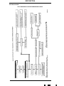
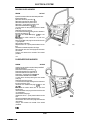
BODY S ECTlON
ILLUSTRATED INDEX- KEY
DESCR IPTlON
No
96........... FRONTSEAT RUNNERS AND ADJUSTER
ASSEMBLY...................................................
97 ........... GEARBOX SPORT MODE SWITCH FINISHER.......
98 ........... GLOVE BOX .....................................................
99 ........... GLOVEBOX LID ................................................
100.......... GLOVEBOX LID LOCK.......................................
101.......... GLOVEBOX LID VENEER PANEL.........................
102.......... GLOVEBOX MIRROR ASSEMBLY .......................
103.......... GUlTER FINISHER............................................
104.......... HANDBRAKE LEVER TRIM.................................
105.......... HEADLAMPTRIM FINISHER..............................
106.......... HEADLINING REAR FINISHER ...........................
107.......... ILLUMINATED SUNVISOR ASSEMBLY ...............
108.......... ILLUMINATED SUNVISOR MIRROR ASSEMBLY..
-.............
INDEX- ILLUSTRATED......................................
-............. INDEX- KEY.....................................................
109.......... INSTRUMENT PANELVENEER PANEL................
110.......... INTERIOR MIRROR...........................................
111.......... LAP BELT INERTIA REEL....................................
112.......... LOWER DOORTRIM FRONT..............................
113.......... LOWER DOOR TRIM REAR ................................
114.......... NUMBER PLATETRIM ......................................
115.......... PASSIVE ECU...................................................
116.......... PASSIVE RESTRAINT........................................
116.......... PASSIVE RESTRAINT........................................
116.......... PASSIVE RESTRAINT........................................
117.......... PASSIVE RESTRAINT GUIDE RAIL......................
118.......... PASSIVE RESTRAINT ECU.................................
119.......... PASSIVE RESTRAINT ECU.................................
120.......... PASSIVE RESTRAINT INERTIA REEL...................
121.......... PASSIVE RESTRAINT MOTOR/DRIVE AND
INERTIA REELASSEMBLIES...........................
122.......... PASSIVE RESTRAINTSYSTEM.
(USA ONLY) ......
123.......... PASSIVE RESTRAINTWARNING CIRCUIT...........
124.......... PETROL FILLER FLAP........................................
125.......... RADIATOR GRILLE SURROUND ........................
126.......... RADIATOR GRILLE-VEHICLESET .....................
127.......... RADIO CONSOLE.............................................
128.......... REAR BEAM.....................................................
129.......... REAR BEAM COVER..........................................
130.......... REAR BUMPER CENTRE BLADE.........................
131.......... REAR BUMPER CENTRE BLADETRIM FINISHER.
132.......... REAR CENTRE SEAT BELTSTATIC......................
133.......... REAR DOOR ARMREST.....................................
134.......... REAR DOOR GLASS..........................................
135.......... REAR DOOR GLASS CHANNEL RUBBER,...........
136.......... REAR DOOR GLASS FRAME..............................
137.......... REAR DOOR HANDLE.......................................
ITEM
~~
0032K
76-1 1
OPERATION
PAGE
VOLUME
No
No
76.70.24.................
76.25.09.................
76.52.03.................
76.52.02 .................
76.52.08.................
76.47.21 .................
76.52.05 .................
76.43.1 1.................
76.13.63.................
76.40.01 .................
76.64.1 2.................
76.1 0.48.................
76.10.50.................
76.00.00.................
76.00.00.................
76.47.24 .................
76.10.51.................
76.73.22.................
76.34.03 .................
76.34.06.................
76.43.22.................
76.73.00 .................
76.73.00.................
76.73.00 .................
76.73.00 .................
76.73.33 .................
76.73.00.................
76.73.00.................
76.73.23 .................
76.76. .......
76-97 ....
76-87 .......
76-87-.......
76-88-.......
76-88- .......
76-89- .......
76-53 .....
76-89- .......
76-24........
76-89. .......
76-93.........
76-93.........
76.0218 .....
76-0319.....
76-99.........
76-90.........
76-115.......
76-53 .......
76-53.........
76-53 .......
76-111.......
76-102.......
76-112.......
76-109.......
76-114.......
76-106.......
76-107.......
76-114.......
4
4
4
4
4
4
4
4
4
4
4
4
4
4
4
4
4
4
4
4
4
4
4
4
4
4
4
4
4
76.73.27 .................
76.73.00.................
76.73.00 .................
76.10.25 .................
76.55.1 5.................
76.55.07 .................
76.25.1 5.................
76.22.27.................
76.22.29.................
76.22.12.................
76.22.14.................
76.73.31
. . .................
76.34.23 .................
76.31.02.................
76.31.14.................
76.31.61 .................
76.58.02.................
76-113.......
76-100.......
76-110.......
76-53........
76-54
...
76-54-.......
76-93 .......
76-96-.......
76-94,.......
76-51_.......
76-52-.......
76-76- .......
76-39- .......
76-38, .......
76-40-.......
76-41- 1 ......
76-41 .......
4
4
4
4
4
4
4
4
4
4
4
4
4
4
4
4
4
_
_
I
_
BODY S ECTlON
178
177
163
145 Et 146
147 141
165,166, In.168. 169
170. 171, 172. 173. 174
138, 139, 140,142 b 143
1 62
151. 1 5 2 153 Et 154
164
ln
15OEt161
149
J76 571
76-12
BODY SECTION
.
ILLUSTRATED INDEX- KEY
ITEM
No
138..........
139..........
140..........
141..........
142..........
143..........
144..........
145..........
146..........
147..........
148..........
149..........
150..........
151..........
152..........
153..........
154..........
156..........
157..........
0PERATIO N
No
REAR DOOR INSIDE HANDLE ............................
76.58.19 .................
REAR DOOR LOCK............................................
76.37.13.................
REAR DOOR LOCKSTRIKER ..............................
76.37.24.................
REAR DOOR LOWERTRIM PAD.........................
76.34.06.................
REAR DOOR OUTER HANDLE OPERATING ROD.. 76.37.11 .................
REAR DOOR REMOTE CONTROL OPERATING
CABLE .........................................................
76.37.68 .................
REAR DOOR SEAL............................................
76.40.02.................
REAR DOOR TRIM PAD VEN EER PANEL.............. 76.47.12.................
REAR DOOR UPPER TRIM PAD..........................
76.34.05.................
REAR DOOR WAIST RAIL MOULDING................ 76.43.05.................
REAR FLOOR CARPEl-.......................................
76.49.03.................
REAR LAMP ASSEMBLY INTERIORTRIM
FINISHER..................................................
76.19.20.................
REAR PARCELTRAY.........................................
76.67.06 .................
REAR QUARTER BUMPER.,. ..............................
76.22.17.................
REAR QUARTER BUMPER BLADE......................
76.25.75 .................
REAR QUARTER BUMPER LOCATING BRACKET. 76.22.22 .................
REAR QUARTER BUMPER MOUNTING RUBBER . 76.22.21 .................
REAR QUARTER UPPERTRIM
PAD LEFT HAND... 76.13.13.................
REAR
QUARTER
UPPERTRIM
PAD
RIGHT
HAND ..........................................................
76.13.43 .................
PAGE
No
76-42,.......
76-43- .......
76-46 .......
76-44- .......
76-97- .......
4
4
4
76-43
76-46- .......
76-45 .......
76-45 .......
76-45,.......
76-79- .......
4
4
4
4
4
4
76-90I. ......
76-90,.......
76-48_.......
76-50- .......
76-50- .......
76-49- .......
76-91- .......
4
4
4
4
4
4
76.70.39 .................
76.70.37 .................
76.70.38.................
76.67.06 .................
76.73.18.................
76.76.01 .................
76.76.02 .................
76.82.01 .................
76.82.23 .................
76.82.44.................
76.82.05 .................
76.82.27.................
76-91-.......
76-77,.......
76-77- .......
76-78- .......
76-78,.......
76-78 .......
76-55- .......
76-55- .......
76-55- .......
76-56- .......
76-57
76-57,.......
76-57 .......
4
4
4
4
4
4
4
4
4
4
4
4
4
76.82.38.................
76.82.15 .................
76.82.19 .................
76.82.39 .................
76.82.42.................
76.82.43 .................
76.82.07 .................
76.46.03.................
76.46.02 .................
76.43.22.................
76.43.25 .................
76-58,....... 4
76-58,....... 4
76-58 ....... 4
76-59- ....... 4
76-59,....... 4
76-60- ....... 4
76-61......... 4
76-92,....... 4
76-91- ....... 4
76-61......... 4
76-62- ....... 4
DESC R I PTI0 N
158..........
159..........
160..........
161..........
, 162..........
163..........
164..........
165..........
166..........
167..........
168..........
169..........
170..........
REAR SEAT ASSEMBLY.....................................
REAR SEAT CUSHION.......................................
REARSEATSQUAB ..........................................
REAR SHELF FINISHER.....................................
REAR SIDE SEAT BELT......................................
SILLTREAD PUTE-FRONT ..............................
SILLTREAD PLATE-REAR ................................
SLIDING ROOF ASSEMBLY...............................
SLIDING ROOF FLANGE FINISHER.....................
SLIDING ROOF MOTOR DRIVE GEAR .................
SLIDING ROOF PANEL......................................
SLIDING ROOF PANEL LIFTING BLOCK..............
SLIDING ROOF PANEL LIFTING BLOCK
VEHICLESFT.................................................
171.......... SLIDING ROOF PANEL SEAL..............................
172.......... SLIDING ROOF PANELTRI M .............................
173.......... SLIDING ROOF PANEL WIND DEFLECTOR..........
174.......... SLIDING ROOF RACK .......................................
175.......... SLIDING ROOF RACK-VEHICLE SET..................
176.......... SLIDING ROOF WIND DEFLECTOR.....................
177.......... STEERING COLUMN LOWER COWL...................
178.......... STEERING COLUMN UPPER COWL....................
179.......... WEATHER STRIP..............................................
180.......... WEATHER STRIP CHANNEL...............................
0032K
76-1 3
_
_
_
VOLUME
4
4
4
BODY SECTION
RESERVED FOR DIMENSIONS OFVEHICLE
4.08 2.9
76-14
BO DY S ECTlON
FRONT BUMPER
RENEW
76.22.08
Remove the side marker lamps and the front side lamp
assemblies.
Remove the two bumper securing bolts, pull the bumper
forward, disconnect the horn feed wires and remove the
screw securing the horn earth to the front bumper.
Remove the bumper assembly (1 Fig 1 ).
Lift the replacement bumper assembly into position.
Reconnect the horn feed and earth wires.
Align, fit arid tighten the two securing bolts, ensuring
that the two quarter bumpers are engaged in the wing
side fixings.
Refit the side marker lamps and front side lamp
assemblies.
DATA
TORQUE FIGURES
Bumper mounting brackets to body (Non Federal)
23-27Nm
Bumper mounting struts to body (Federal) 23-27Nm
Bumper to bumper bracket (Non Federal) 40-50”
Bumper to bumper strut (Federal) 4WiONm
Guide block to mounting bracket 3.5-4.75Nm
Horns to bracket 22-28Nm
Mounting bracket guide block to body 7.5-10Nm
Fig 1
4
SPANNER SIZES
8mm
1Omm
13mm
19mm
No 20 Torx
0384b
FRONT BUMPER ASSEMBLY
OVERHAUL
76.22.09
Remove the front side and marker lamp assemblies and
remove the two bumper securing bolts.
Pull the bumper assembly forward and disconnect the
horn feed and earth wires.
Remove the bumper assembly complete from the
vehicle.
Remove the centre blade trim finisher (1 Fig 2), remove
the centre blade to bumper securing screws (2 Fig 2)
and remove the blade (3 Fig 2).
76-1 5
476 na
Fig 2
BODY SECTION
Remove both quarter bumper securing bolts (4 Fig 2
page 15) and remove the quarter bumper blades (5 Fig 2
page 15).
Remove the rubber bumper upper cover securing screws
(3 Fig 2 page 15).
Remove the centre blade bracket/cover retaining clip
securing screws (4 Fig 2 page 15) and remove the
bracket (5 fig 2 page 15).
Remove the nuts securing the quarter bumper to the
rubbers.
Remove the cover to bumper lower securing screws and
remove the cover, remove the horn bracket securing
screw and remove the bracket from the bumper beam.
Replace any damaged component and reverse the
removal procedure to reassembleand fit to the vehicle.
DATA
TORQUE FIGURES
Bumper mounting brackets to body (Non Federal)
23-27Nm
Bumper mounting struts to body (Federal) 23-27Nm
Bumper front blade to beam 5-7Nm
Bumper side blade to beam 5-7Nm
Bumper side to mounting block 5- 7Nm
Bumper to bumper bracket (Non Federal) 4O-so”
Bumper to bumper strut (Federal) 40-50”
Flexible mounting block to beam 5-7Nm
Guide block to mounting bracket 3.5-4.75Nm
Horns to bracket 22-28Nm
Mounting bracket guide block to body 7.5-1ONm
Fig 1
a
SPANNER SIZES
8mm
1Omm
13mm
19mm
No 20 Torx
0392b
FRONT BUMPER CENTRE BLADE
J76 316
RENEW
76.22.37
Remove the trim finisher from its locating lugs.
Remove the centre section securing screws (2 Fig 2),
manoeuvre the blade (1 Fig 2) clear of its locating clips
and remove the centre section (3 Fig 2).
Fit the replacement blade to the retaining clips and align
the fixing holes, fit and tighten the securing screws and
refit the finisher to the centre blade.
76-16
Fig 2
B0 DY S ECTlO N
DATA
TORQUE FIGURES
Bumper mounting brackets to body (Non Federal)
23-27Nm
Bumper mounting struts to body (Federal) 23-27Nm
Bumper to bumper bracket (Non Federal) 40-50Nm
Bumper to bumper strut (Federal) 40-50"
Guide block to mounting bracket 3.5-4.75Nm
Horns to bracket 22-28Nm
Mounting bracket guide block to body 7.5-lONm
SPANNER SIZES
8mm
I Ornm
13mm
19mm
No 20 Torx
0386b
Fig 1
FRONT ENERGY ABSORBING STRUT
RENEW
76.22.31
Remove the side marker lamps and the front side lamp
assemblies.
Remove the two bumper securing bolts, pull the bumper
forward, disconnect the horn feed wires and remove the
screw securing the horn earth to the front bumper.
Remove the bumper assembly.
Cut the ratchet strap securing the block connector to the
strut mounting bracket.
Remove the bolt securing the strut (1 Fig 1), and remove
the strut assembly.
Secure the strut in a vice.
Remove the locknut securing the bracket to the strut.
Note 'the number of threads protruding from the bracket
and remove the strut.
Reverse the removal procedure to refit the replacement
strut to the vehicle.
Lift the replacement bumper assembly into position and
connect up the horn feed and earth wires.
Align, fit and tighten the two securing bolts, ensuring
that the two quarter bumpers are engaged in the wing
side fixings.
Refit the side marker lamps and front side lamp
assemblies.
DATA
TORQUE FIGURES
Bumper mounting brackets to body (Non Federal)
23-27Nm
Bumper mounting struts to body (Federal) 23-27Nm
Bumper to bumper bracket (Non Federal) 40-50Nm
Bumper to bumper strut (Federal) 40-5ONm
Guideblock to mounting bracket 3.5-4.75Nm
Horns to bracket 22-28Nm
Mounting bracket guide block to body 7.5-lONm
76-17
BODY SECTION
DATA
SPANNER SIZES
8mm
I Omm
13mm
19mm
No 20 Torx
16698177
FRONT CROSSMEMBER
RENEW
76.10.05
Jack up the front of the vehicle.
Fit camber tie-down bars (Service Tool JD 133) to the
road spring pans.
NOTE: If, for any reason, the front crossmember is being
stripped down, Service Tool JD 115 must be used in
place of JD 133, and the coil springs must be removed
prior to crossmember removal (operation 60.20.01 ). JD
133 is for operations where the crossmember is being
removed for access only.
Lower the vehicle and settle the suspension.
Open the bonnet.
Engage the camber tie-down bars in the suspension
turrets.
Remove the front shock absorber upper securing nuts,
washersand buffers (Fig 1).
Slacken off the road wheel nuts 1/4 of a turn each.
Jack up the front of the vehicle. Support with axle
stands.
Mark the wheel to stud relationship, and remove the
front road wheels.
Disconnect the left hand brake pad wear sensor block
connector.
Remove the lower guide pin bolt from the left hand
caliper, and pivot the caliper upwards to gain access to
the brake pads (Fig 2).
NOTE: Use an open-ended spanner to hold the guide
pin during removal. This will prevent damage to the
rubber dust cover,
Remove the brake pads.
Remove the upper guide pin bolt, remove the caliper,
and re-position the caliper away from the suspension
fig 1
area.
Disconnect the right hand brake pad wear sensor block
connector.
Remove the right hand brake pads and caliper.
Turn the steering to the straight ahead position. Remove
the ignition key.
Remove the lower column (3 Fig 3) to steering rack
securing bolt/nut (1,2, Fig 3).
I
76-18
BODY SECTION
Disengagethe splines from the rack pinion (4 Fig 3 page
18).
NOTE: At this point, the lower column cannot be
completely disconnected from the pinion.
Remove the P.A.S. pipe to crossmember retaining
clamps and spacing washers.
Position a drain tray under the front of the vehicle.
Disconnect the steering rack return pipe, and drain the
system.
Fit blanking plugs to the pipe and rack.
Disconnect the steering rack feed pipe, and drain the
system.
Fit blanking plugs to the pipe and rack.
Re-positionthe pipes away from the suspension area.
Remove the drain tray.
Remove the engine mounting securing nuts.
Attach JD 124 rear engine lifting eye, fit and align
Service Tool MS 536 engine support bracket (Fig 1).
Engage the hookto the lifting eye (2.9 ENGINE ONLY).
Disconnect Nos. 1 and 2 plug leads.
Attach 18G 1465 rear engine lifting eye, fit and align
Service Tool MS 536 engine support bracket (Fig 2).
Engage the hook to the lifting eye (3.6 ENGINE ONLY).
Tighten the hook nut to take the weight of the engine.
Slacken off the crossmember rear mounting bolts/nuts.
Remove the nuts. Do not removethe bolts at this stage.
Slacken off the mounting clamp plate securing bolts (Fig
3).
Take the weight of the crossmember assembly on the
jack.
Finally, remove the rear mounting bolts and spacers.
Remove the crossmember front mounting to chassis
securing nuts (Fig 4).
NOTE: The bolts nuts remain captive.
Carefully lower the assembly from the vehicle. Ensure
that the calipers, pipes and lower column do not foul
during removal.
Change over all ancilliary components to the new
crossmernber.
Position the crossmember assembly on the jack under
the vehicle,
Raise the assembly into position and align the shock
absorbers.
Align the engine mountings, P.A.S. pipes, lower column
and rear mountings.
Align the front crossmember mounting securing bolt
holes.
Fit and tighten the front mounting securing bolts (Fig 4).
using a second jack, align the left hand rear mounting
(Fig 3).
Fig 4
76-1 9
BODY SECTION
Fit and align the outer spacer.
Fit the bolt through the chassis, the outer spacer and the
mounting.
Fit the inner spacer.
Push the bolt fully home, fit but do not tighten the nut.
Lower and remove the jack from under the mounting.
Repeat the above procedure for the right hand rear
mounting.
Lower and remove the jack from under the crossmember.
Finally tighten the rear mounting securing bolts/nuts.
Tighten the rear mounting clamp plate securing bolts.
Ensure the steering wheel and rack are in the straight
ahead position.
Re-position the lower column on to the pinion and align
the clamp slot.
Fit and tighten the clamp bolthut.
Remove the blanking plugs from the P.A.S. pipes and
rack.
Fit new '0' rings to the pipes. Connect the pipes to the
rack. Tighten the union nuts.
Refit the P.A.S. pipe clamps.
Slacken off the MS 536 hook nut. Remove the hook.
Remove Service Tool MS 53B.
Remote the lifting eye.
Fit and tighten the engine mounting securing nuts.
Refit the calipers. Refit the brake pads.
Refit the road wheels.
Lower the vehicle from the axle stands -Settle the
suspension.
Refit the shock absorber upper buffers, washers, and
securing nuts.
Release the tie-down bars from the suspension.
Raise the vehicle. Remove the tie-down bars from the
road spring pans. Lower the vehicle.
Bleed the P.A.S. system as follows:
Top up the P.A.S. reservoir.
Start the engine.
Turn the steering wheel to full left hand lock.
Turn the steering wheel to full right hand lock.
Top up the reservoir. Fit the reservoir cap.
Close the bonnet.
76-20
BODY SECTION
DATA
SERVICE TOOLS
JD 133 ne-down bars
JD 124Rear lifting eye (2.9ENGINE)
186 1465Rear liftrtg eye (3.6 ENGINE)
MS 53B Engine support bracket
TORQUE FIGURES
Caliper to carrier 31-4ONm
Wheelnut to wheelstud (steel wheel) 65-85"
Wheelnut to wheel stud (alloy wheel) 88-102Nm
Shock absorber to upper mounting4
3
"I? A.S. feedpipe to rack 19-23Nm
P.A.S. return pipe to rack 79-23Nm
SPANNER SIZES
13mm
14mm
16mm
I7mm
19mm
22mm
1 5 / 1 6A F
ns m
Fig 1
01LS/G R EASES/SEAlANTS
P.A.S. reswvoirDEXRON2D or Type G (M2C33G)
0051G
FRONT QUARTER BUMPER
RENEW
76.22.16
Remove the front beam 76.22.26.
Remove the quarter bumper assembly to mounting
rubber securing nuts (1 Fig 1).
Remove the quarter bumper assembly.
Remove the reflector, remove the quarter bumper blade
securing nuts and bolts (2 Fig 7 ) and remove the quarter
bumper blade (3 Fig 1).
Reverse the removal procedure to refit the replacement
bumper.
DATA
TORQUE FIGURES
Bumper quarter blade to quarter bumper 5-7Nm
Bumper side to flexible mounting block 5-7Nm
SPANNER SIZES
8mm
7 Omm
76698
76-21
BODY SECTION
FRONT QUARTER BUMPER
MOUNTING RUBBER
RENEW
76.22.19
Removethe front beam 76.22.26.
Removethe front quarter bumper 76.22.16
9emove the nuts (1 Fig 1) securing the beam to the
flexible mounting rubber and remove the mounting-from
the beam.
Reverse the removal procedure to fit the replacement
rubber.
DATA
TORQUE FIGURES
Bumper mounting brackets to body (Non Federal)
23-27Nm
Bumper mounting struts to body (Federal) 23-27Nm
Bumper to bumper bracket (Non Federal) 40-501Vm
Bumper to bumperstrut (Federal) 40-5ONm
Guideblock to mounting bracket 3.5-4.75Nm
Horns to bracket 22-28Nm
Mounting bracket guide block to body 7.5-10Nm
m ST7
Fig 1
SPANNER SIZES
8mm
1Omm
13mm
19mm
No 20 Tom
1669EV66
FRONT QUARTER BUMPER LOCATING
BRACKET
RENEW
76.22.20
Removethe front beam 76.22.26
Slacken and remove the screws securing the locating
bracket to the body and remove the bracket (1 Fig 2).
Reverse the removal procedure to refit the replacement
bracket.
DATA
TORQUE FIGURES
Bumper mounting brackets to body (Non Federal)
23-27Nm
Bumper mounting struts to body (Federal) 23-27Nm
Bumper to bumper bracket (Non Federal) 40-50"
Bumper to bumper strut (Federal) 40-5ONm
Guide block to mounting bracket 3.5-4.75Nm
76-22
Fig 2
BODY SECTION
DATA
TORQUE FIGURES
Horns to bracket 22-28Nm
Mounting bracket guide block to body 7.5-1ONm
SPANNE’RSIZES
8mm
1Omm
13mm
19mm
No 20 Torx
1669W66
FRONTQUARTER BUMPER BLADE
RENEW
76.22.73
Remove the front beam 76.22.26
Remove the nuts and bolts (1 Fig 1) securing the blade
(2 Fig 1 ) to the bumper.
Remove and discard the blade.
Reverse the removal procedure to refit the replacement
blade.
DATA
TORQUE FIGURES
Bumper mounting brackets to body (Non Federal)
23-27Nm
Bumper mounting struts to body (Federal) 23-27Nm
Bumper front blade to beam 5-7Nm
Bumper side blade to beam 5-7Nm
Bumper side to mounting block 5-7Nm
Bumper to bumper bracket (Non Federal) 40-5ONm
Bumper to bumper strut (Federal) 40-50”
Flexiblemounting block to beam 5-7Nm
Guideblock to mounting bracket 3.5-4.75Nm
Horns to bracket Z-28Nm
Mounting bracket guide block to body 7.5-1ONm
SPANNER SIZES
8mm
1Omm
13mm
19mm
NO20 Torx
16698
76-23
Fig 1
BODY SECTION
HEADLAMPTRIM FINISHER
RENEW
76.40.01
Removethe radiator grille 76.55.07.
Removethe headlamp assembly 86.40.06/7.
Remove the four screws (1 Fig 1) securing the trim to
the headlamp unit.
Reverse the removal procedure to refit the finisher.
0379b
BONNET
RENEW
76.16.01
Open the bonnet.
Remove the right hand insulation pad securing screws
and remove the pad.
Disconnectthe bonnet illumination lamp multi plugs.
Apply tape to the forward edge of the bonnet behind the
grille surround.
Slacken the bonnet securing bolts (1 Fig 2) and
disconnect the bonnet support struts (2 Fig 2).
Remove the bonnet securing bolts and remove the
bonnet.
Remove the trim pad securing screws and remove the
trim pad.
Remove the bonnet lamp securing screws, remove the
tape securing the lamp harness to the bonnet and
removethe lamps.
Remove the bonnet lock spring assemblies, remove the
bonnet catch securing bolts and remove the catch.
Remove the bonnet support pivots and place the bonnet
aside.
Reverse the removal procedure to refit, ensuring that the
bonnet is aligned before the bonnet securing bolts are
finally tightened.
Fig 1
DATA
SPANNER SIZES
13mm
OOlOb
BONNET INSULATION PAD
RENEW
59.2
76.16.06
Open the bonnet and remove the ten self tapping screws
and plain washers securing the insulation to the bonnet.
Hold the replacement insulation pad in position and
secure with the ten screws and plain washer. Close the
bonnet.
76-24
BODY SECTION
BONNETSEALING RUBBER REAR
RENEW
76.16.04
Open the bonnet.
Starting from one side of the vehicle, prise the rubber
seal (Fig 1) from the bulkhead/ inner wings. Discard the
old seal.
Starting from the centre of the vehicle, fit the
replacement seal to the bulkheadhnner wings, gradually
working outwards.
Ensure the seal is firmly pressed down onto the channel
edge.
Cut the outer edae of the seal as shown (Fig 1),
Press the remainder of the trim firmly down on each
inner wing and trim off until they are of equal length.
Close the bonnet.
0394b
BONNET STRIKER ASSEMBLY
RENEW
76.16.24
Open the bonnet, slacken the locknut (1 Fig 2) and
unscrew the striker (2 Fig 2).
Replace any damaged componentsand reassemble.
A distance of 62 mm (1 Fig 3) from the end of the striker
to the locknut is an advisable length to set the assembly
to, prior to fitment to the vehicle.
Adjust the assembly until the bonnet is flush with the
wing and the bulkhead.
Close the bonnet.
!I I
Fig 2
I
0388b
BONNET LOCK
RENEW
76.00.00
Open the bonnet and disconnect the lock operating
cable (4 Fig 4) from the lock.
Remove the bolts securing the lock (5 Fig 4) to the body
and remove the lock.
Reverse the removal procedure to refit the replacement
lockensuring that, prior to tightening, the lock is aligned
with the striker.
DATA
TORQUE FIGURES
Bonnet lock to body 7.5-10,25Nm
SPANNER SIZES
8mm
1Omm
16698/8
76-25
Fig 3
BODY SECTION
BONNETGAS STRUT
RENE
Open the bonnet.
76.16.15
Fit a suitable bonnet support.
Displace the upper strut pivot (1 Fig 1) from the pivot
bolt.
Repeatfor the lower.
Remove and discard the strut (2 Fig 1).
Reverse the removal procedure to refit the replacement
strut.
16696/7 1
BONNET GAS STRUT-VEHICLE SET
RENEW
76.16.1 6
Open the bonnet.
Fit a suitable bonnet support.
Displace the upper strut pivot (1 Fig 1) from the pivot
bolt.
Repeat for the lower.
Remove and discard the strut (2 Fig 1).
Repeat the procedure for the other strut.
Reverse the removal procedure to refit the replacement
struts.
Fig 1
16698172
BONNET LOCK CONTROL CABLE
RENEW
76.16.29
Open the bonnet.
Slacken the clamp bolt (1 Fig 2) securing the cable (4
Fig 2) to the lock actuator.
Disconnect the cable from the lock and from the
mounting clip (2 Fig 2).
Displace the cable from the bulkhead mounting clips
and remove the ratchet straps securing the cable to the
pipes and harnesses.
Displace the cable from the remaining large ratchet
Fig 2
straps.
Open the front door.
Removethe dash liner.
Pull the release handle and disconnect the cable (1 Fig
3) from the release handle and bracket.
Pull the cable through the bulkhead grommet and
discard.
Reverse the removal procedure to fit the replacement
cable.
DATA
3
SPANNER SIZES
II
Fig 3
8mrn
I Omm
16698/72
76-26
BODY SECTION
BONNET LOCK CONTROLCABLE
ASS E M B LY-VEHICLE SET
RENEW
76.16.35
Open the bonnet.
Slacken the clamp bolt (1 Fig 1) securing the cable (4
Fig 1) to the lock actuator.
Disconnect the cable from the lock and from the
mounting clip (2 Fig 1).
Displace the cable from the bulkhead mounting clips
and removethe cable securing ratchet straps.
Displace the cable from the remaining large ratchet
straps.
Open the driving side door.
Remove the dash liner.
Pull the release handle and disconnect the cable (1 Fig
2) from the release handle (2 Fig 2) and bracket.
Pull the cable through the bulkhead grommet and
discard.
Repeat the procedure for the remaining cable.
Reverse the removal procedure to fit the replacement
cables.
Fig 1
DATA
SPANNER SIZES
8mm
1Omrn
16698/72
BONNET LOCK RELEASE HANDLE
RENEW
76.16.30
Open the bonnet.
Slacken the clamp bolt securing the cable to the lock
actuator.
Repeat the procedure for the other side.
Open the driving side door.
Remove the dash liner.
Disconnect the inner cables (1 Fig 2) from the bonnet
release handle (2 Fig 2).
Remove the bolts securing the bonnet release handle (3
Fig 2) to the body, remove the cables from the handle
and remove from the vehicle.
Reverse the removal procedure to fit the replacement
handle.
DATA
TORQUE FIGURES
Bonnet lock release handle to body 7-1ONm
SPANNER SIZES
8mm
IOmp
76-27
mas
Fig 2
BODY SECTION
BONNET HINGE (NON FEDERAL)
RENEW
76.16.11
Remove the screw (situated at the top) securing the
front grille and remove the grille (Fig 1).
Open the bonnet.
Secure the bonnet with a suitable support.
Remove the bonnet hinge securing nuts and bolts (Fig
2).
Remove and discard the hinge.
Position the replacement hinge on the front panel
locating the studs in the holes.
Open the hinge and align with the securing holes in the
bonnet.
Fit and tighten the hinge to bonnet securing bolts.
Fit but do not fully tighten the the hing securing nuts.
Remove the bonnet support and carefully lower the the
bonnet to check the alignment, open the bonnet slacken
the hinge securing nuts and position the bonnet as
required.
Fully tighten the securing nuts.
Close the bonnet and check the alignment.
Refit the radiator grille and close the bonnet.
6 6m
Fig 1
DATA
SPANNER SIZES
13mm
16698/83
BONNET HINGEVEHICLESET (NON
FEDERAL)
RENEW
76.16.12
Remove the two screws (situated at the top) securing
each front grille and remove the grille (Fig 1).
Open the bonnet.
Secure the bonnet with a suitable support.
Remove the bonnet hinge securing nuts and bolts (Fig
4
*
Remove and discard the hinge.
Position the replacement hinge on the front panel
locating the studs in the holes.
Open the hinge and align with the securing holes in the
bonnet.
Fit and tighten the hinge to bonnet securing bolts.
Fit but do not fully tighten the the hinge securing nuts.
Remove the bonnet support and carefully lower the the
bonnet to check the alignment.
76-28
Fig 2
BODY SECTION
Open the bonnet, slacken the hinge securing nuts and
position the bonnet as required.
Fullytightenthe securing nuts.
Close the bonnet and check the alignment.
Repeat the procedurefor the other hinge.
Refit the radiator grille and close the bonnet.
DATA
SPANNER SIZES
13mm
16698183
BONNET HINGE (FEDERAL)
Fig 1
RENEW
76.16.11
Remove the screw (situated at the top) securing the
front grille and remove the grille (Fig 1).
Remove ttie two bolts each side securing the grille
support brackets to the body.
Remove the grille assembly and remove the grille
support brackets and four plastic thread inserts (Fig 2).
Open the bonnet.
Secure the bonnet with a suitable support.
Remove the bonnet hinge securing nuts and bolts
Remove and discard the hinge.
Position the replacement hinge on the front panel
locatingthe studs in the holes.
Open the hinge and align with the securing holes in the
bonnet.
Fit and tighten the hinge to bonnet securing bolts.
Fit but do not fully tighten the the hinge securing nuts.
Remove the bonnet support and carefully lower the the
bonnet to check the alignment.
Open the bonnet, slacken the hinge securing nuts and
position the bonnet as required.
Fullytighten the securing nuts.
Close the bonnet and check the alignment.
Refit the radiator grille and surround.
Close the bonnet.
DATA
SPANNER SIZES
1Omm
13mm
~
76-29
Fig 2
JIB 311
BODY SECTION
BONNET HINGEVEHICLE SET
(FEDERAL)
RENEW
76.16.12
Remove the two screws (situated at the top) securing
each front grille and remove the grille (Fig 1).
Remove the two bolts each side securing the grille
support brackets to the body.
Remove the grille assembly and remove the grille
support brackets and four plastic thread inserts (Fig 2).
Open the bonnet.
Secure the bonnet with a suitable support.
Remove the bonnet hinge securing nuts and bolts (Fig
JmY
3)
Fig 1
Remove and discard the hinge.
Position the replacement hinge on the front panel
locating the studs in the holes.
Open the hinge and align with the securing holes in the
bonnet.
Fit and tighten the hinge to bonnet securing bolts.
Fit but do not fully tighten the the hinge securing nuts.
Remove the bonnet support and carefully lower the the
bonnet to check the alignment, open the bonnet slacken
the hinge securing nuts and position the bonnet as
required.
Fully tighten the securing nuts.
Close the bonnet and check the alignment.
Repeat the procedure for the other hinge.
Refit the radiator grille and surround.
Close the bonnet.
""I
Fig 2
DATA
SPANNER SIZES
1Ornrn
13mm
16698/85
FRONT DOOR ARMREST
RENEW
76.34.22
Open the door.
Removethe front door trim pad veneer
panel 76.47.1 1.
Remove the front door upper trim pad 76.34.02.
Removethe front door lower trim pad 76.34.03.
Remove the screws securing the armrest to the trim pad
(Fig 4). disconnect the speaker.blockconnector (Fig 4)
and remove the armrest from the trim pad.
~
76-30
liJ
Fin 2
BODY SECTION
Remove the screws (Fig 4 page 30) securing the switch
panel support bracket (Fig 4 page 30) to the armrest (Fig
4 page 30) and removethe bracket.
Displacethe switch panel/ashtray (for access).
Disconnect the puddle lamp feed wires and the securing
screws, remove the lamp assembly.
Remove the switch and harness assembly from the
armrest and discard the armrest.
Reverse the removal procedure to refit the replacement
armrest.
2
DATA
SPANNER SIZES
No 4 Pozi'
FRONT DOOR GLASS
RENEW
76.31.01
Open the door.
Removethe front door trim pad veneer panel 76.47.1 1.
Removethe front door upper trim pad 76.34.02.
Removethe front door lower trim pad 76.34.03.
Fittape (1 Fig 1) over the door glass (2 Fig 1) and frame
(3 Fig 1) to secure the glass.
Remove the screws securing the window lift motor to
the door frame.
Remove the screws securing the window regulator lift
guide.
Disconnect the exterior mirror and regulator multi plug
connectors.
Disconnect the window lift mechanism from the door
glass.
Lower the window lift motor to the bottom of the door
and displace the channel rubber from the front channel
for access to the securing screw.
Remove the screw (Fig 2) securing the door glass frame
to the front mounting bracket
Remove the screws (Fig 2) securing the door glass
frame to the door, remove the spacer plate and remove
the door gla- and frame assembly, remove the tape from
the glass and removethe glass from the frame.
Reverse the removal procedure to refit the replacement
glass.
76-31
578 921
Fig 1
Fig 2
BODY SECTION
DATA
TORQUE FIGURES
Door glass clamping strip to door 71ONm
Door glass regulator and slide channel to door 7-lONm
Setscrew front lower frame fixing to door 7-1ONm
Setscrew front upper frame fixing to door 7-1ONm
Setscrew rear lower frame fixing to door 7-1ONm
Set screw rear upper frame fixing to door 7-1ONm
SPANNER SIZES
1Omm
Torxbit No 30
0016b
FRONT DOOR GLASS CHANNEL
RUBBER
RENEW
76.31.13
Open the door.
Removethe front door trim pad veneer panel 76.47.1 1.
Remove the front door upper trim pad 76.34.02.
Remove the front door lower trim pad 76.34.03.
Removethe exterior mirror 76.10.52.
Removethe front door waist rail moulding 76.43.04.
Removethe front door glass 76.31-01
Removethe glass channel rubber (1 Fig 1).
Refit the replacement rubber to the channel in frame,
engage corners and then fully seat the remainder of the
rubber and reverse the remaining removal procedure to
refit.
DATA
TORQUE FIGURES
Door g l a s clamping strip to door 7-7ONm
Door glass regulator and slide channel to door 7-IONm
Setscrew front lower frame fixing to door 7-1ONm
Setscrew front upper frame fixing to door 7-1ONm
Set serew rear lower frame fixing to door 7-1ONm
Set screw rear upper frame fixing to door 7-1ONm
SPANNER SIZES
1Omm
Torxbit No 30
Fig 1
BODY SECTION
FRONT DOOR GLASS FRAME
RENEW
76.31.51
Open the door
Remove the front door trim pad veneer panel 76.47.11.
Remove the front door upper trim pad 76.34.02.
Remove the front door lower trim pad 76.34.03.
Remove the exterior mirror 76.10.52.
Remove the front door waist rail moulding 76.43.04.
Remove the front door glass 76.31.01
Remove the front door glass channel rubber 76.31.1 3.
Remove the upper frame seal from the frame and place
the frame aside.
Apply soft soap to the frame apeture and starting with
the rear of the seal at the front of the frame slide the seal
into position.
Reversethe removal procedure to refit.
DATA
TORQUE FIGURES
Fig 1
Door glass clamping strip to door 7-1ONm
Door glass regulator and slide channel to door 7-1OlVm
Set screw front lower frame fixing to door 7-l0Nm
Set screw front upper frame fixing to door 7-1ONm
Set screw rear lower frame fixing to door 7-lONm
Set screw rear upper frame fixing to door 71ONm
SPANNER SIZES
Torx bit No 30
0020b
FRONT DOOR HANDLE
RENEW
76.58.01
Open the door
Remove the front door trim pad veneer panel 76.47.1 1
Remove the front door upper trim pad 76.34.02.
Removethe front door lower trim pad 76.34.03.
76-33
516-
BODY SECTION
Removethe door aperture closing plate.
Displace the weather shield and remove the door handle
to linkage to lock mechanism retaining clip.
Disconnectthe door handle linkage.
Cut and remove the ratchet strap securing the switch
harness.
Disconnect the switch harness multi plug and reposition
away from the door locating tangs.
Remove the door handle assembly securing nuts and
remove the clamp (Fig 1).
Displace the door handle from the door to provide
access to the private lock operating rod.
Disconnect the operating rod from the plastic cam and
remove the door handle.
Removethe operating rod.
Remove the screws securing the central locking micro
switch and discard the tape securing the harness to the
handle body.
Removethe micro switch assembly.
Remove the handle clamp securing studs.
Discardthe handle.
Reverse the removal procedure to fit the replacement
door handle.
'
Fig 1
DATA
TORQUE FIGURES
Door handle to door 3.5-4.5Nm
SPANNER SIZES
8mm
0058b
FRONT DOOR INSIDE HANDLE
RENEW
76.58.20
Open the door.
Removethe front door trim panel veneer panel 76.47.11
Reposition the inner cable (1 Fig 2) from the door
handle, disconnect the outer handle assembly securing
sleeve and disconnect the cable from the handle.
Operate the handle for access, remove the screw (2 Fig
2) and bolt (2 Fig 2) securing the handle assembly.
Removethe handle and discard.
Reverse the removal procedure to refit the replacement
handle.
DATA
TORQUE FIGURES
Inner handle to door 4-5.4Nm
SPANNER SIZES
I Ornm
76-34
2
J76 405
Fig 2
B0 DY S ECTI0 N
FRONT DOOR LOCK
RENEW
76.37.12
Open the door
Removethe front door trim pad veneer panel 76.47.11.
Remove the front door upper trim pad 76.34.02.
Remove the front door lower trim pad 76.34.03.
Remove the front door glass 76.31.01
Displace the inner lock control rod securing clip and
remove the rod/knob assembly.
Remove the remote cable to bracket retaining clip and
repositionthe cable from the bracket.
Reposition the inner cable from the lock release arm and
remove the outer handle operating rod retaining clip.
Reposition the rod from the retaining clip and displace
the rod from the private lock.
Cut and remove the door lock harness to door panel
ratchet straps and disconnect the multi plugs.
Remove the lock securing screws and remove the lock
assembly.
Removethe linkage rod.
Remove the motor securing screws and remove the
motor.
Discardthe lock assembly.
Reverse the removal procedure to refit the lock,
DATA
TORQUE FIGURES
Door lock to door 7-1ONm
SPANNER SIZES
8mm
I Omm
No 30 Torx
O029b
76-35
Fig 1
BODY SECTION
FRONT DOOR REMOTE CONTROL
OPERATING CABLE
RENEW
76.37.67
Open the door
Removethe front door trim pad veneer panel 76.47.1 1.
Removethe front door upper trim pad 76.34.02.
Remove the front door lower trim pad 76.34.03.
Remove the clip securing the inner cable to the door lock
and disconnect the cable from the lock assembly.
Remove the clip (2 Fig 1) securing the outer cable (3 Fig
1) to the door lock assembly, disconnect the
cable from the bracket (4 Fig 1) and the inner cable from
the interior door handle securing sleeve.
Disconnect the cable from the interior handle assembly,
remove the securing sleeve from from the cable.
Remove and discard the cable.
Reverse the removal procedure to refit the replacement
cable.
0031b
Fig 1
FRONT D O O R T R I M PAD VENEER
PANEL
RENEW
76.47.11
Open the door.
Position the inner door handle in the open position and
remove the inner handle escutcheon plate blank (1 Fig
2)
Remove the screw (2 Fig 2) securing the escutcheon
plate (3 Fig 2), removethe plate and gasket.
Carefully pull the veneer panel (4 Fig 2) to release the
retaining clips.
Remove the screws securing the retaining clip and
remove the retaining clip assemblies.
Discard the veneer panel.
Reverse the removal procedure to fit the replacement
veneer.
1
0041b
Fig 2
FRONT DOOR LOWER T R I M PAD
RENEW
76.34.03
Open the door.
Removethe front door trim pad veneer panel 76.47.1 1.
Removethe front door upper trim pad 76.34.02.
Remove the lower trim pad securing screw, remove the
puddle lamp lens and remove the screw securing the
lower trim pad/puddle lamp.
76-36
BODY S ECTlON
Displace the trim pad from the retaining clips and
disconnect the door harness block connectors.
Remove the lower trim pad assembly.
Remove the frontdoor armrest 76.34.22
Remove the door speaker securing nuts and remove the
speaker.
Remove the door pocket to trim pad securing screws
( Fig 1 ) and remove the door pocket,
Remove the locating bracket securing screws and
remove the bracket.
Discard the trim pad.
Fit the locating bracket to the replacement trim and
reverse the remaining procedure to refit the trim pad.
0024b
FRONT DOOR WAIST RAIL MOULDING
RENEW
76.43.04
Open the door
Remove the front door trim pad veneer panel 76.47.1 1.
Remove the front door upper trim pad 76.34.02.
Remove the front door lower trim pad 76.34.03.
Carefully remove the moulding from the front door.
Using a suitable block to prevent damage to the
moulding, carefully fit and seat the replacement
moulding to the door.
Reverse the remaining procedure to fit the replacement
moulding.
0033b
FRONT DOOR LOCK STRIKER
RENEW
76.37.23
Open the door and slacken the pin (1 Fig 2), remove the
pin from the ‘B’post and collect the washer.
Reverse the removal procedure to fit a replacement
striker pin.
DATA
TORQUE FIGURES
Striker pin to ‘8‘post 24-30”
Fig 2
SPANNER SIZES
17mm
76-37
BODY SECTION
FRONT DOOR SEAL
RENEW
76.40.01
Open the door.
Rempve the end panel finishers and pull the top finisher
clear of the tread plate.
Remove the five tread plate securing screws and remove
the tread plate.
Remove the seal and clean the channel (Fig 1).
Apply Kent clear sealer to the 'C' channel butt joints and
Solumin to the section of the seal above the sill section.
Position the replacement seal and locate in the upper
corners, secure with tape and using soft soap seat the
door seal in the channel.
Remove the tape and slide the front lower edge and
corner of theseal into position.
Clean off all soft soap and refit thesill.tread plate.
DATA
OILS/SEALANTS/LU BRICANTS
Fig 1
J 4 3y
Two 'C channel buttjoints Kent clear sealer
Seal (above sill section) Solumin
1669W69
FRONT DOOR UPPER TRIM PAD
RENEW
76.34.02
Open the door.
Remove the front door trim pad veneer panel 76.47.1 1
Remove the upper trim pad securing clip (Fig 2) and
screws (Fig 2).
Lift the trim pad to release from the door, remove the
inner waist rail seal.
Reverse the removal procedure to refit the replacement
upper trim pad.
0023b
REAR DOOR GLASS
RENEW
Fig 2
76.31.02
Open the door.
Remove the rear door trim pad veneer panel 76.47.1 2.
Remove the rear door upper trim pad 76.34.05.
Remove the rear door lower trim pad 76.34.06.
.-
76-38
BODY S ECTlO N
Removethe door aperture plastic closing panels.
Fit adhesive tape (1 Fig 1) over the door frame to secure
the glass.
Remove the screws and nuts (2 Fig 1) securing the
window lift motor to the door glass.
Remove the screws securing the window lift guide to the
door and carefully displace the mechanism (3 Fig 1)
from the door glass and position in the bottom of the
door.
Remove the grommet to gain access to the rear frame
upper securing screws and remove the screws securing
the glass frame to the door.
Lift the glass and frame assembly from the door, remove
the adhesive tape securing the glass to the door frame
and remove the glass.
Reverse the removal procedure to refit the replacement
glass.
DATA
TORQUE FIGURES
Lc?)
Fig 1
Door glass clamping strip to door 7-1ONrn
Door glass regulator and slide channel to door 8- 1ONm
Setscrew front lower frame fixing to door 7-7ONrn
Set screw frcnt upper frame fixing to door 7-10Nm
Set screw rear inboard frame fixing to door 7-1ONm
Setscrew rear lower frame fixing to door 7-1ONm
Setscrew rear upper frame fixing to door 7-1ONm
SPANNER SIZES
1Omm
Torx bit No 30
0017b
REAR DOOR ARMREST
RENEW
76.34.23
Open the door
Remove the front door trim pad veneer panel 76.47.1 1.
Remove the front door upper trim pad 76.34.02.
Remove the front door lower trim pad 76.34.03.
Remove the screws securing the armrest to the trim pad
(Fig 2).
Disconnect the speaker block connector and remove the
armrest from the trim pad.
76-39
Fig 2
J76 327
BODY SECTION
Remove the screws securing the switch pane; support
bracket to the armrest and remove the bracket.
Displace the switch panel/ashtray for access and
disconnect the puddle lamp feed wires.
Remove the puddle lamp securing screws and remove
the lamp assembiy.
Remove the switch and harness assembly and discard
the armrest.
Reverse the removal procedure to refit.
0028b
REAR DOOR GLASS CHANNEL RUBBER
RENEW
76.31.I 4
Open the door.
Remove the front door trim pad veneer panel 76.47.1 1.
Remove the front door upper trim pad 76.34.02.
Remove the front door lower trim pad 76.34.03.
Remove the rear door waist rail moulding 76.43.05.
Remove the rear door glass 76.31.02.
Remove the plastic finisher screw and plastic finisher.
Remove the glass channel rubber (Fig 1 ).
Place the replacement rubber in the frame and fit the
upper corners of the rubber to the frame first and fully
seat the remaining rubber in the frame.
Reverse the remaining procedure to refit.
DATA
TORQUE FIGURES
Door glass clamping strip to door 7-1OMm
Door glass regulator and slide channel to door 8-1ONm
Set screw front lower frame fixing to door 7-1ONm
Set screw front upper frame fixing to door 7-IONm
Set screw rear inboard frame fixing to door 7-IONm
Set screw rear lower frame fixing to door 7- 1ONm
Setscrew rear upper frame fixing to door 7-1ONm
SPANNER SIZES
1Omm
Torx bit No 30
0019b
76-40
Fig 1
BODY SECTION
REAR DOOR GLASS FRAME
RENEW
76.31.61
Open the door.
Remove the front door trim pad veneer panel 76.47.11,
Remove the front door upper trim pad 76.34.02.
Remove the front door lower trim pad 76.34.03.
Remove the rear door waist rail moulding 76.43.05.
Remove the rear door glass 76.31.02.
Remove the rear door glass channel rubber 76.31.I 4.
Remove the outer finisher securing screw and remove
the outer finisher.
Remove the upper seal from the frame.
Apply soft soap to the upper seal fitment area of the
replacementframe.
Starting with the front of the seal at the rear of the frame,
slide the seal into position.
Reverse the remaining removal procedure to refit the
replacementframe.
DATA
Fig 1
TORQUE FIGURES
Door glass clamping strip to door 7-10Nm
Door glass regulator and slide channel to door 8-1ONm
Setscrew front lower frame fixing to door 7-1ONm
Setscrew front upper frame fixing to door 7-lONm
Setscrew rear inboard frame fixing to door 7-/ONm
Setscrew rear lower frame fixing to door 7-1ONm
Set screw rear upper frame fixing to door 7-lONm
SPANNER SIZES
lOmrn
Torx bit No 30
0022b
REAR DOOR HANDLE
RENEW
76.58.02
Open the door.
Remove the rear door trim pad veneer panel 76.47.1 1
Remove the rear door upper trim pad 76.34.05.
Remove the rear door lower trim pad 76.34.06.
76-41
Y
BODY SECTION
Removethe door aperture plastic closing panel.
Carefully displace the door weather shield for access.
Remove the door handle operating rod to lock retaining
clip peg and reposition the rod from the retaining clip.
Remove the front nul securing the handle clamp bracket
(1 Fig 1) and slacken but do not remove the rear
securing bolt and remove the clamp bracket.
Remove the handle assembly and remove the securing
stud and bolt.
Discardthe handle.
Reverse the removal procedure to refit the replacement
handle.
DATA
TORQUE FIGURES
Door handle to door 3.5-4.5Nm
SPANNER SIZES
8mm
Fig 1
0059b
REAR DOOR INSIDE HANDLE
RENEW
76.58.19
Open the door.
Remove the rear door trim pad veneer panel. 76.47.1 2
Disconnectthe inner cable (Fig 2) from the door handle
and displace the outer cable to handle assembly securing
sleeve.
Disconnect the cable from the handle assembly, operate
the handle for access,remove the screw and bolt
securing the handle assembly, remove and discard the
handle.
Reverse the removal procedure to refit the repiacewment
handle.
DATA
TORQUE FIGURES
Door inside handle to door 4-5.4Nm
SPANNER SIZES
1 Omm
0060b
76-42
BO DY S ECTlON
-
-
REAR DOOR LOCK
RENEW
76.37.13
Open the door
Remove the front door trim pad veneer panel 76.47.1 1.
Removethe front door upper trim pad 76.34.02.
Remove the front door lower trim pad 76.34.03.
Remove the rear door glass 76.31.02
Displace the inner lock control rod securing clip and
remove the rod/knob assembly.
Remove the remote cable to bracket retaining clip and
reposition the cable from the bracket.
Reposition the inner cable from the lock release arm and
remove the outer handle operating rod retaining clip.
Repposition the rod from the retaining clip and displace
the rod from the private lock.
Cut and remove the door lock harness to door panel
ratchet straps and disconnect the multi plugs.
Remove the lock securing screws (1 Fig 1) and remove
the lock assembly.
Remove the linkage rod.
Remove the motor securing screws and remove the
motor.
Discard the lock assembly.
Reverse the removal procedure to refit the replacement
lock.
DATA
TORQUE FIGURES
Door lock to door 7-1ONm
SPANNER SIZES
8mm
I Omm
No 30 Torx
0030b
REAR DOOR REMOTE CONTROL
OPERATING CABLE
RENEW
76.37.68
Open the door
Remove the front door trim pad veneer panel 76.47.11
Removethe front door upper trim pad 76.34.02.
Remove the front door lower trim pad 76.34.03.
-j
-,
J7b 5 7 0
Fig 1
BODY SECTION
Disconnect the cable from the centre support bracket
and remove the clip securing the interior locking rod to
the linkage, remove the locking rod.
Release and remove the clip securing the operating rod
to t h e cable and disconnect the cable from the lock.
Remove the clip securing the outer cable to the lock
bracket, disconnect the cable from the bracket.
Reposition the inner cable to the interior handle
assembly locking sleeve, disconnect the inner cable from
the interior handle and repositionthe cable.
Remove the securing sleeve from the cable and remove
The cable.
Reverse the removal procedure to refit the cable to the
door.
0032b
REAR DOOR LOWER TRIM PAD
RENEW
76.34.06
Open the door.
Remove the front door trim pad veneer panel 76.47.11.
Remove the front door upper trim pad 76.34.02.
Remove the rear door trim finisher, remove the trim pad
centre securing screw.
Remove the puddle lamp lens and the lower trim pad
securing screw.
Displace the trim pad from the retainingclips, disconnect
the door block harness connectors and remove the trim
pad assembly.
Remove the rear door armrest and the nuts securing the
speaker.
Remove the speaker.
Remove the screws securing the door pocket to the trim
pad and removethe door pocket.
Discard the trim pad.
Reverse the removal procedureto refit the trim pad.
0026b
76-44
BODY S ECTlON
REAR DOOR TRIM PAD VENEER PANEL
RENEW
76.47.12
Open the door.
position the inner door handle in the open position and
remove the inner handle escutcheon plate blank (1 Fig
1 ).
Remove the screw (2 Fig 1) securing the escutcheon
plate (3 Fig 1), remove the plate and gasket.
Carefully pull the veneer panel (4 Fig 1) to relaese the
retaining clips.
Remove the Screws securing the retaining clip and
remove the retaining clip assemblies.
Discard the veneer panel.
Reverse the removal procedure to fit the replacement
veneer.
/3
0043b
REAR DOOR UPPER TRIM PAD
2
J76m
RENEW
76.34.05
Fig 1
Open the door.
Remove the rear door trim pad veneer panel 76.47.1 2.
Remove the upper trim panel securing screws, lift the
panel to remove from the door mounting and remove the
panel.
Remove the top channel securing nuts and remove the
top channel assembly.
Discard the upper trim pad.
Reverse the removal procedure to refit the replacement
panel.
0025b
REAR DOOR WAIST RAIL MOULDING
RENEW
76.43.05
Open the door.
Carefully unclip the moulding (1 Fig 2) from the door
flange.
Discard the moulding.
Using a suitable block to protect the moulding carefully
fit the replacement moulding to the door.
Close the door.
76-45
fig 2
BODY SECTION
REAR DOOR LOCK STRIKER
RENEW
76.37.24
Open the door and slacken the pin (1 Fig 1), remove the
pin from the 'D' post and collect the washer.
Reverse the removal procedure to fit a replacement
striker pin.
DATA
TORQUE FIGURES
Striker pin to 'D'post24-30"
SPANNER SIZES
17mm
16698/61
REAR DOOR SEAL
RENEW
Fig 1
76.40.02
Open the door.
Remove the end panel finishers and pull the top finisher
clear of the tread plate.
Remove the five tread plate securing screws and remove
the tread plate.
Remove the seal (Fig 2) and clean the channel.
Apply Kent clear sealer to the ' C channel butt joints and
Solumin to the section of the seal above the sill section.
Position the replacement seal and locate in the upper
corners, secure with tape and using soft soap Seat the
door seal in the channel.
Remove the tape and slide the front lower edge and
corner of the seal into position.
Clean off all soft soap and refit the sill tread plate.
DATA
01LS/SEALANTS/LU BRICANTS
J7B 345
Three 'Cchannel buttjoints Kent clear sealer
Seal (abovesill section) Solumin
16698/70
76-46
BODY SECTION
REAR BUMPER ASSEMBLY
RENEW
76.22.15
Remove both rear fog lamp assemblies and rear side
marker lamps (where fitted).
Remove the bumper securing bolts and collect the
spacers and remove the rear bumper assembly (Fig 1).
Guide the replacement bumper onto the guides at the
sides of the vehicle and fit the securing bolts.
Tighten the bolts and refit the rear fog and marker lamps
(where fitted).
DATA
TORQUE FIGURES
Bumper mounting brackets to body (Non Federal)
23-27Nm
Bumper mounting struts to body (Federalj 23-27Nm
Bumper to bumper brackbt (Non Federal) 40-5ONm
Bumper to body inner (Federal) 23-27Nm
Bumper to fixings bumper beam (Federal) 39-5ONm
Bumper to body inner (Non Federal) 23-27Nm
Bumper to fixings bumper beam (Non Federal)
39~50Nm
Guideblock to mounting bracket 3.5-4.75Nm
Mounting bracket guide block to body Z5-10Nm
Fig 1
SPANNER SIZES
8mm
I Omm
13mrn
17mm
19mm
No 20 Torx
0375h
REAR BUMPER ASSEMBLY
OVERHAUL
76.22.18
Remove the rear fog guard and marker lamps (where
fitted).
Remove the rear bumper securing bolts and remove the
rear bumper assembly.
Remove the central plastic finisher (1 Fig 2), remove the
centre blade rubber securing screws (2 Fig 2) and
remove the rubber.
Remove the quarter bumper securing nuts and bolts (6
Fig 2) and remove the rear quarter bumper (1 0 Fig 2).
76-47
Fig 2
BODY SECTION
Remove the bumper cover blade retaining clip securing
screws and remove the clips.
Reverse the removal procedure to reassemble ensuring
that any damged components are replaced.
Refit The bumper assembly to the vehicle.
DATA
TORQUE FIGURES
Bumper front blade to beam 5-7Nm
Bumper mounting brackets to body (Non Federal)
23-27Nm
Bumper mountingstruts to body (Federal) 23-27Nm
Bumper side to flexible mounting block 5-7Nm
Bumper side blades to beam 5- 7Nm
Bumper to bumper bracket (Non Federal) 40-50Nm
Bumper to body inner (Federal) 23-27Nm
Bumper to fixings bumper beam (Federal) 39-50Nm
Bumper to body inner (Non Federal) 23-27Nm
Bumper to fixings bumper beam (Non Federal)
39-5ONm
Flexible mounting block to beam 5-7Nm
Guideblack to mounting bracket 3.5-4,75Nm
Mounting bracket guide block to body 7.5-IONm
Fig 1
SPANNER SIZES
8mm
1Omm
13mm
I7mm
19mm
No 20 Torx
0377b
REAR QUARTER BUMPER
RENEW
76.22.17
Open the boot.
Move the rear boot carpet for access to the rear fog
guard lamp harness and position approximately 3" of
harness 'slack' through the grommet for each lamp.
Remove the beam securing bolts and spacers and
carefully move the beam assembly rearwards for access
to the rear quarter bumper mountings.
Remove the reflector from the quarter bumper.
76-48
.
..
.. .. ..
.....
. .....
--
BODY SECTION
Remove the nuts (Fig 1) securing the bumper (Fig 1) to
the mounting rubber.
Carefully reposition the quarter bumper from the studs
and remove the quarter bumper assembly.
Reposition the beam onto the strut and remove the
quarter blade to quarter bumper securing nuts and bolts.
Remove the blade from the bumper and place aside.
Reverse the removal procedure to refit the replacement
bumper.
DATA
TORQUE FIGURES
Bumper beam to bumper bracket (Non Federal)
40-5ONm
Bumper beam to bumper strut (Federal) 39-50Nm
Bumper quarter blade to quarter bumper 5-7Nm
Bumper side to flexible mounting block 5- 7Nm
SPANNER SIZES
Bmm
1Omm
19mm
Fig 1
16698/63
REAR QUARTER BUMPER MOUNTING
RUBBER
RENEW
76.22.21
apen the boot.
Remove the rear quarter bumper 76.22.1 7.
Remove the nuts securing the mounting rubber (1 Fig 2)
to the beam and remove the mounting rubber.
Reverse the removal procedure to refit the replacement
rubber.
DATA
TORQUE FIGURES
Bumper beam to bumper bracket (Non Federal)
40-50Nm
Bumper beam to bumper strut (Federal) 39-5ONm
Bumper quarter blade to quarter bumper 5- 7Nm
Bumper side to flexible mounting block 5-7Nm
SPANNER SIZES
8mm
1Omm
19mm
Fig 2
BODY SECTION
REAR QUARTER BUMPER LOCATING
BRACKET
RENEW
76.22.22
Open the boot.
Remove the rear quarter bumper 76.22.1 7.
Slacken and remove the screws securing the locating
bracket (1 Fig 1) to the body.
Remove the locating bracket.
Reverse the removal procedure to refit the replacement
bracket.
DATA
TORQUE FIGURES
Bumper beam to bumper bracket (Non Federal)
40-50Nm
Bumper beam to bumper strut (Federal) 39-50Nm
Bumper quarter blade to quarter bumper 5-7Nm
Bumper side to flexible mounting block 5-7Nm
Fig 1
SPANNER SIZES
Bmrn
I Omm
19rnm
16698/67
REAR QUARTER BUMPER BLADE
RENEW
76.22.75
Open the boot.
Move the rear boot carpet for access to the rear fog
guard lamp harness and position approximately 3” of
harness ‘slack through the grommet for each lamp.
Remove the beam securing bolts and spacers and
carefully move the beam assembly rearwards for access
to the rear quarter bumper mountings.
Remove the reflector from the quarter bumper.
Remove the nuts securing the bumper to the mounting
rubber.
Carefully reposition the quarter bumper from the studs
and remove the quarter bumper assembly.
Reposition the beam .onto the strut and remove the
quarter blade to quarter bumper securing nuts and bolts
(1 Fig2).
Remove the blade from the bumper and place aside (2
Fig 2).
Reverse the removal procedure to refit the replacement
bumper blade.
76-50
Fig 2
BODY S ECTlON
DATA
TORQUE FIGURES
Bumper beam to bumper bracket (Non Federal)
40-5ONm
Bumper beam to bumper strut (Federal) 39-5ONm
Bumper quarter blade to quatter bumper 5- 7Nm
Bumper side to flexible mounting block 5-7Nm
SPANNER SIZES
8mm
lOmm
19mm
1669W69
" I
REAR BUMPER CENTRE BLADE
RENEW
76.22.12
Prise off the black plastic trim finisher (1 Fig I ) , remove
the five screws (2 Fig 1) securing the blade (3 Fig l ) ,
release the blade from the securing clips and remove the
bumper blade.
Fit the replacement centre blade to the retaining clips, fit
and tighten the five securing screws and refit the trim
finisher.
DATA
TORQUE FIGURES
Bumper mounting brackets to body (Non Federal)
23-27Nm
Bumper mounting struts to body (Federal) 23-27Nm
Bumper to bumper bracket (Non Federal) 40-5ONm
Bumper to body inner (Federal) 23-27Nm
Bumper to fixings bumper beam (Federal) 3-50"
Bumper to body inner (Non Federal) 23-27Nm
Bumper to fixings bumper beam (Non Federal)
39-50Nm
Guide block to mounting bracket 3.5-4.75Nm
Mounting bracket guide block to body 7.5-10Nm
SPANNER SIZES
8mm
I Omm
13mm
17mm
19mm
NO20 Torx
0374b
76-51
Fig 1
9
BODY SECTION
REAR BUMPER CENTRE B L A D E T R I M
FINISHER
RENEW
76.22.14
Open the boot.
Move the carpet to gain access to the rear fog guard
lamp harnesses.
Reposition approximately 3" of slack through the
grommets for each fog guard lamp.
Remove the bolts securing the rear beam.
Remove the spacers.
Carefully position the beam assembly rearwards to gain
access to the trim finisher.
Unclip and remove the trim finisher (1 Fig 1) taking care
not to dislodge the beam assembly from the struts.
Reverse the removal procedure to refit the trim finisher.
DATA
TORQUE FIGURES
Bumper mounting brackets to body (Non Federal)
23-27Nm
Bumper mounting struts to body (Federal) 23-27Nm
Bumper to bumper bracket (Non Federal) 40-5ONm
Bumper to bumperstrur (Federal) 40-50"
Fig 1
SPANNER SIZES
8mm
I Omm
13mm
19mm
76698/78
EXTERIOR M I R R O R
RENEW
76.10.52
Open the front door.
Remove the door trim pad veneer panel and the upper
trim pad.
Remove the screws securing the mirror attachment plate
and remove the plate (Fig 2).
Cut the ratchet strap securing the mirror harness.
Disconnect the mirror harness block connectors, remove
the mirror securing screws and remove the mirror
assembly.
Reverse the removal procedure to refit.
0003b
76-52
Fig 2
BODY SECTION
GUlTER FINISHER
RENEW
76.43.11
Open the front and rear doors (one side), remove the
four screws and remove the B post capping.
Remove the drip moulding securing screws (1 Fig 1)
and remove the moulding to six light trim finisher and
remove the drip moulding (2 Fig 1).
Fit the replacement drip moulding into position and align
to the body fixing holes.
Fit and tighten the fixing screws.
Fit the six light to moulding finisher, position and tighten
the four screws.
Close the doors.
DATA
TORQUE FIGURES
Drip moulding to body 2-4Nm
Fig 1
0398b
NUMBER P L A T E T R I M ( W H E R E
FITTED)
RENEW
76.43.22
Open the boot lid, remove the three self tapping screws
and prise the trim , starting at the upper side edge and
work round and release the eight locating plugs from the
lower boot panel and remove the trim.
Reverse the removal procedure to refit the trim after new
sealant has been applied to the trim.
0361b
PETROL FILLER FLAP
RENEW
m 411
76.10.25
Depress flap and list as shown and lift the corner. Open
flap and remove the two nuts, spring and plain washers
and remove the flap (Fig 2).
Slacken the locknut securing the locking pin and remove
the locking pin.
Reverse the removal procedure to refit the flap ensuring
that the locking pin is adjusted to ensure that the flap
shuts flush with the wing top.
76-53
Fig 2
BODY SECTION
DATA
TORQUE FIGURES
Latch fixing nut to latching bolt2-3Nm
SPANNER SIZES
8mm
1Omm
OILS/SEALANTS LUBRICANTS
Filler flap hinge leaf Shell Retinax 'A
0363b
RADIATOR GRILLE VEHICLE SET
RENEW
76.55.07
Remove the two screws (1 Fig 1 ) securing each front
grille (2 Fig 1 ) and remove the grille.
Refit the replacement grilles by engaging the lower tag
of each grille into its locating slot and securing at the top
with the screw.
Fig 1
0383b
RADIATOR GRILLE SURROUND
RENEW
76.55.15
Remove the two front grilles and remove the two bolts
(1 Fig 2) each side securing the grille support brackets to
the body.
Remove the grille assembly and remove the grille
support brackets and the four thread inserts.
Fit -the brackets and thread inserts to the replacement
grille surround and secure the surround to the body with
the four bolts.
Refit the two front grilles.
DATA
SPANNER SIZES
1Ornrn
0382b
.~
76-54
BODY SECTION
SILLTREAD PLATE- REAR
RENEW
76.76.02
open the door.
Remove the end panel finishers and pull the top finisher
clear of the tread plate.
Remove the five tread plate securing screws (1 Fig 1)
and remove the tread plate (2 Fig 1).
Fit the replacement tread plate into position and secure
with the fixing screws.
fit the new sill finisher and push in the end panel
finishers.
Close the door.
16698/56
SILLTREAD PLATE-FRONT
,//
/
Fig 1
RENEW
76.76.01
Open the door.
Remove the end panel finishers and pull the top finisher
clear of the tread plate.
Remove the five tread plate securing screws (1 Fig 2)
and remove the tread plate (2 Fig 2).
Fit the replacement tread plate into position and secure
with the fixing screws.
Fit the new sill finisher and push in the end panel
finishers.
Close the door.
0399b
SLIDING ROOF ASSEMBLY
RENEW
76.82.01
Open the doors.
Removethe sliding roof panel 76.82.05
Release the clip securing the interior lamp.
Displace the panel assembly from its mounting position
and disconnect the block connectors.
Place the panel to one side.
Remove the cantrail crash roll left and right hand
76.13.1 0.
Removethe headlining rear finisher 76.64.1 2.
Remove the rear quarter upper trim pad right hand
76.13.43.
Remove the rear quarter upper trim pad left hand
76.13.43.
Remove the sun visor vehicle set 76.10.17.
Removethe sliding roof flange finisher 76.82.23.
Remove the headlining to sliding roof aperture securing
Clips (1 Fig 3).
Fig 2
m38
Fig 3
m 351
BODY SECTION
Recline the seats fully for access and release the left hand
rear headlining clip (1 Fig 2), reposition the headlining
onto the rear parcel shelf for access.
Disconnect the sliding roof motor block connector.
Cut and remove the drain tube to roof assembly securing
ratchet straps.
Disconnect the drain tubes from the sliding roof
assembly.
Remove the bolts securing the support bracket (1 Fig 1 )
to the sliding roof.
Remove the bolts securing the left and right hand
suppot%bracket (Fig 1 ) t o the roof.
Remove the right hand support brackets and lower the
roof assembly from the left hand support brackets and
remove from the vehicle via the front passenger door.
Remove the spacers and place the roof aside.
Reverse the removal procedure ensuring that prior to
final tightening of the securing bolts that the roof is
centralised with an even 4mm gap all round the aperture.
JIB 372
DATA
TORQUE FIGURES
Fig 1
Outer seal retainer2-3Nm
Plate and lifting block to bracket 2.3-3.4Nm
SPANNER SIZES
13mm
0080b
SLIDING ROOF FLANGE FINISHER
76.82.23
RENEW
Open the door.
Open the sliding roof.
Carefully remove the sliding roof aperture finisher (Fig 2)
from the aperture ensuring that the headlining trim edges
are not damaged.
Reverse the removal procedure t o refit the finisher.
0085b
\
i
Fig 2
J16 357
76-56
BODY SECTION
SLIDING ROOF MOTOR DRIVE GEAR
RENEW
76.82.44
Open the doors.
Remove the sliding roof flange finisher 76.82.23.
Remove the sun visor vehicle set 76.1 0.1 7.
Remove the cantrail crash roll left and right hand
76.13.1 0.
Removethe sliding roof motor 86.76.01
Remove the drive gear from the sliding roof motor.
Reverse the removal procedure to fit the replacement
gear ensuring that prior to assembly the gear is coated
with grease.
0090b
SLIDING ROOF PANEL
RENEW
76.82.05
Open the door.
Open the sliding roof.
Remove the sliding roof panel securing screws and
partially close the roof.
Remove the sliding roof panel assembly.
Remove the lifting block securing nuts and screws and
(1 Fig 2) removethe lifting block (2 Fig 2) and plates
(3
. Fis
- 2).
.
Remove the screws (1 Fig 7 ) and drill out the ’pop’ rivets
(2 Fig 1) securing the roof panel seal front and rear
retaining plate.
Remove the retaining plates.
Remove the seal.
Discard the roof panel.
Reverse the removal procedure ensuring that prior to
final tightening of the securing screws that the roof is
centralised with an ’even’ 4mm gap all round the
aperture.
Fig 1
0081b
SLIDING ROOF PANEL LIFTING BLOCK
fig 2
RENEW
76.82.27
Open the door.
Open the sliding roof.
Remove the nuts (1 Fig 2) securing the lifting blocks (2
Fig 2) and remove.
Reverse the removal procedure to refit the replacement
lifting block ensuring that prior to final tightening of the
securing nuts, the roof panel alignment is checked.
0086b
76-57
m311
B0DY S ECTI0N
SLIDING ROOF PANEL LIFTING BLOCK
VEHICLE SET
ADJUST
76.82.38
Open the door.
Open the sliding roof.
Slacken the nuts (Fig 1) securing the lifting blocks (2
Fig 1) and reposition as required.
Tighten the securing nuts and carefully slide the panel
shut to check the alignment with the roof.
0087b
SLIDING ROOF PANELSEAL
RENEW
76.82.15
Open the door.
Open the sliding roof.
Remove the sliding roof panel securing screws and
partially close the roof.
Remove the sliding roof panel assembly.
Remove the lifting block securing nuts and screws and
remove the lifting blocks and plates.
Remove the screws (1 Fig 2) and drill out the 'pop' rivits
(Fig 2) securing the roof panel seal front and rear
retaining plate.
Remove the retaining plates (3 Fig 2).
Removethe seal (4 Fig 2).
Discard the roof panel.
Reverse the removal procedure ensuring that prior to
final tightening of the sec'uring screws that the roof is
centralised with an 'even' 4mm gap all round the
aperture.
Fig 1
0083b
SLIDING ROOF PANELTRIM
ASSEMBLY
RENEW
76.82.19
Open the door.
Remove the sliding roof panel 76.82.05
Fully close the sliding roof, remove the trim panel
securing clips, partially open the sliding roof, remove the
screws securing the front bridge plate and collect the
bridge plate.
Remove the trim panel and clean the rubbers.
Reverse the removal procedure to fit the replacement
trim.
76-58
\3
Fig 2
m LO
BODY SECTION
SLIDING ROOF PANEL WIND
DEFLECTOR
ADJUST
76.82.39
Open the door.
Open the sliding roof.
Slacken the screws securing the wind deflector (Fig l ) ,
adjust as required and tighten the deflector securing
screws.
Carefully slide the panel shut to check the alignment
with the roof.
0089b
SLIDING ROOF RACK
RENEW
76.82.42
Open the doors.
RemoGethe sliding roof panel 76.82.05
Removethe sliding roof flange finisher 76.82.23.
Remove the sun visor vehicle set 76.1 0.17.
Remove the cantrail crash roll left and right hand
76.1 3.1 0.
Remove the sliding roof motor 86.76.01
Release the interior lamp panel securing clip and release
the panel assembly from its mounted position.
Disconnect the block connectors (Fig 2) and place the
panel aside.
Remove the sliding roof motor 86.76.01
Remove the tape and cut the ratchet straps securing the
rack tubes together and taking care t o ensure that the
headlining is not soiled by the rack, remove the rack end
tube sections.
Manually slide the roof panel rearwards and remove the
relevent mounting bracket securing bolts.
Removethe bracket.
Remove the screws securing the rack tube clamp to the
sliding roof, manually close the roof and remove the rack
to roof panel carrier securing nut.
Displace the rack tube assembly from its guide, open up
and reposition the tube clamp over the rear tube and rack
bracket.
Holding the rear tube in position, disconnect the front
rack tube from the rear rack tube.
Release the rack from the rear tube and carefully remove
the rack.
Grease the replacement rack, fit the rack to the front rack
tube, reposition the rack into the rear rack tube
approximately 12 in. ensuring that the clamp is not
displaced along the tube.
76-59
Fig 1
Fig 2
BODY SECTION
Reposition the front rack tube and connect to the rear
rack tube, ensure that the rack tube to sliding roof
assembly rubber is correctly positioned.
Position the clamp over the union and connect the rack
to the carrier.
Tighten the rack securing nut and manually slide the roof
fully rearwards.
Position the rack tube into the guide, close the clamp
and align the mounting bracket, fit and tighten the clamp
securing screws.
Position the rack tube end sections and secure the tube
with ratchet straps and tape.
Position the rack tubes for fitting the motor, manually
close the roof, ensure that the carriers are fully forward,
refit the roof motor and reverse the remaining removal
procedureto refit.
SLIDING ROOF RACKVEHICLE SET
RENEW
76.82.43
Open the doors.
Removethe sliding roof panel 76.82.05
Removethe sliding roof flange finisher 76.82.23.
Removethe sun visor vehicle set 76.1 0.1 7.
Remove the cantrail crash roll left and right hand
76.1 3.1 0.
Remove the sliding roof motor 86.76.01
Release the interior lamp panel securing clip and release
the panel assembly from its mounted position.
Disconnect the block connectors (Fig 1) and place the
panel aside.
Remove the sliding roof motor 86.76.01
Remove the tape and cut the ratchet straps securing the
rack tubes together and taking care to ensure that the
headlining is not soiled by the rack, remove the rack end
tube sections.
Manually slide the roof panel rearwards and remove the
relevent mounting bracket securing bolts.
Remove the bracket.
Remove the screws securing the rack tube clamp to the
sliding roof, repeat the procedure for the second side,
manually close the roof and remove the rack to roof
panel carrier skuring nut.
Displace the rack tube assembly from its guide, open up
and reposition the tube clamp over the rear tube and rack
bracket.
Holding the rear tube in position, disconnect the front
rack tube from the rear rack tube.
Fig 1
BODY SECTIUN
Release the rack from the rear tube and carefully remove
the rack.
Repeat the procedurefor the second side.
Grease the replacement racks, fit the rack to the front
rack tube, reposition the rack into the rear rack tube
approximately 12 in. ensuring that the clamp is not
displaced along the tube.
Reposition the front rack tube and connect to the rear
rack tube, ensure that the rack tube to sliding roof
assembly rubber is correctly positioned.
Position the clamp over the union and connect the rack
to the carrier.
Tighten the rack securing nut and repeat the procedure
for the second side.
Manually slide the roof fully rearwards.
Position the rack tube into the guide, close the clamp
and align the mounting bracket, fit and tighten the clamp
securing screws.
Repeat the procedure for the second side.
Position the rack tube end sections and secure the tubes
with ratchet straps and tape.
Position the rack tubes for fitting the motor, manually
close the roof, ensure that the carriers are fully forward,
refit the roof motor and reverse the remaining removal
procedure to refit.
Fig 1
0092b
SLIDING ROOF WIND DEFLECTOR
RENEW
76.82.07
Open the door.
Open the sliding roof.
Remove the screws securing the wind deflector (Fig 1)
and remove the deflector assembly.
Remove and discard the deflector gaskets.
Place the deflector to one side.
Reverse the removal procedure to refit the deflector
ensuring that prior to tightening of the securing screws
the sliding roof is carefully closed to check the alignment
of the deflector.
I
0082b
Fig 2
WEATHER STRIP
RENEW
76.43.22
Remove the door upper trim pad and slide the weather
strip (1 Fig 2) from the channel (2 Fig 2).
Reverse the removal procedureto refit.
0357b
BODY S ECTlON
WEATHER STRIP CHANNEL
RENEW
76.43.25
Remove the door upper trim pad.
Remove the heater vent plenum chamber securing
screws, and pull the chamber clear of upper trim, remove
the nuts and springs washers (1 Fig 1) and remove the
channel (2 Fig 1).
Reversethe removal procedure to refit the channel.
0356b
WINDSCREEN GLASS- LOWER
FINISHER
RENEW
76.43.41
Using a suitable implement under one corner of the seal,
lift out of its aperture and peel back across the vehicle.
Coat the replacement seal with a liquid soap solution
and starting at one end of the aperture, press the seal into
position working across the vehicle, cut the seal to
length and finally seat.
1
Fig 1
0395b
BOOT LID STRIKER
ADJUST
76.19-04
Open the boot and remove the rear finisher screws and
remove the finisher.
Slacken the stricker plate securing bolts (I Fig 2). adjust
the striker to ensure the boot lid lines up with both rear
wings, and tighten the securing bolts.
Fit the rear finisher and secure with the screws.
Close the boot.
DATA
SPANNER SIZES
Fig 2
1Omm
13mm
0381b
76-62
BODY SECTION
BOOT LID
RENEW
76.19.01
Open the bonnet and disconnect the battery. open the
boot, cut the clips securing the harness to the boot lid.
Disconnect the boot lamp and boot lock multi-plugs and
disconnect the number plate lamp feed wires.
Remove the hingeto boot lid securing bolts (Fig 1), hold
the boot open using a suitable prop.
Disconnect the gas struts from the boot lid pivots and
remove the boot lid.
Remove the two number plate lamp units, two screws
each, and the boot illumination lamp. Remove the boot
lid lock and remove the boot lock finisher and collect the
finisher gasket.
Glue the gasket to the boot lock finisher, fit the finisher to
the boot lid and secure with the two plain washers and
nuts.
Refit the number plate lamps and the boot illumination
lamp, refit the boot lock mechanism. lift the boot lid hack
into position, and fit but do not tighten the securing bolts
and connect the struts to the boot lid pivot bolts.
Carefully shut the boot to align with the rear wings, open
the boot and tighten the four securing bolts.
Skure the harness to the boot lid with harness straps
and boot lid clips.
Connect the boot lamp and lock multi-plugs and
connect the number plate light feed wires.
Close the boot.
Reconnect the battery and close the bonnet.
Fig 1
DATA
SPANNER SIZES
13mm
0367b
BOOT LID SEAL
RENEW
76.19.06
Open the boot and remove the rear trim panel securing
screws and remove the rear trim panel, and remove the
seal from the boot flange.
Clean the seal mounting flange, fit the new seal in
position (1 Fig 2), start at the lock striker and work back.
Fig 2
. .
BODY SECTION
Cut the seal to the correct length and finally fit the seal to
the flange.
Refit the rear trim finisher and secure with the screws.
Close the boot lid.
0366b
BOOT LID GAS STRUT
RENEW
76.19.27
Open the boot.
Insert screwdriver and remove the strut (Fig 1 ) from the
top pivot and repeat the operation for the lower pivot.
Fit the strut to the lower pivot first to aid reassembly.
Reverse the removal procedure to refit the replacement
strut.
NOTE: Change only one strut at once.
0370b
BOOT LID STRUT PIVOT BOLTS
RENEW
Fig 1
76.00.00
Open the boot.
Remove the strut (Fig 1 ), slacken and remove the upper
pivot bolt (Fig 1 ), collect the spring washer (Fig 1 ).
Repeat the operation for the lower bolt.
Reverse the removal procedureto refit the bolts.
Close the boot lid.
DATA
4
0369b
BOOT LID LOCK MECHANISM
RENEW
76.19.25
Open the boot, disconnect the operating rod from the
remote linkage (spring clip).
Remove the two lock assembly securing bolts (2 Fig 2).
remove the lock from the boot lid, disconnect the
multi-plug (4 Fig 2) and remove the assembly from the
vehicle.
Reverse the removal procedure to refit.
DATA
TORQUE FIGURES
Latch to boot lid 7-IONm
Lock to boot lid 5-7Nm
76-64
..
I
I
Fig 2
1
k
BODY SECTION
DATA
SPANNER SIZES
8mm
01LS/S EALANTWLU BR ICANTS
Lock moving parts Valvolene Tectyl4008
0371b
BOOT LOCK RELEASETRIGGER
HANDLE
RENEW
76.19.15
Remove the boot lock assembly, remove the roll pin and
remove the lever.
Refit the replacement and reverse the removal procedure.
0373b
BOOT LOCK FlNSlHER
RENEW
76.433
Open the boot, disconnect the number plate lamp
connections, and rernclve the lens assemblies.
Remove the two nuts (1 Fig 1) and plain washers
securing the finisher, remove the finisher and gasket.
Glue the gasket (2 Fig 1) to the replacement finisher (3
Fig l ) , fit to the boot lid and secure with the nuts and
plain washer.
Refit the number plate lamp assemblies and connections.
Close the boot annd reconnect the battery.
DATA
TORQUE FIGURES
Finisher to boot lid 5-7Nm
SPANNER SIZES
8mm
0368b
76-65
Fig 1
BODY SECTION
BOOT LID LOCK BARREL
RENEW
76.19.19
Remove t h e boot'lock assembly, remove the four screws
and separate the front plate from the operating assembly.
Remove the locking pin and spring (1 Fig 1) and push
the barrel (2 Fig 1) out from inside.
Reverse the procedure to refit the replacement, ensuring
that the locating hole lines up with the holes in the
housing.
037213
BOOT LID LOCK STRIKER
RENEW
76.19.12
n s 431
Open the boot, remove the 4 screws (1 Fig 2) securing
the boot trim and remove the trim and carpet.
Remove the 2 bolts (2 Fig 2) and spring washers and
remove the striker plate (3 Fig 2).
Reverse the removal procedure and adjust the striker
plate until the boot lid is flush wirh the rear wings when
closed.
DATA
TORQUE FIGURES
Striker to rear trunk panel 7-lONm
SPANNER SIZES
1Ornm
0365b
BOOTVENTILATOR OUTLET
RENEW
80.15.66
Remove the boot side trims and remove the 2 bolts and
plain washers (4 Fig 3) securing the boxes (5 Fig 3) to
the boot floor in either side.
Reverse the removal procedure to refit the boxes,
ensuring that the two earth wire eyelets are refitted to
each rear securing bolt and that the exhaust grommets
are aligned with the apetures in the body side vents.
DATA
TORQUE FIGURES
Ventilator box to boot floor6-8Nm
SPANNER SIZES
I Omm
0362b
76-66
/"
riy L
BODY SECTION
BOOT LID HINGEVEHICLE SET
BENEW
'
76.19.28
open the boot, cut and remove the boot harness straps
and move the harness away from the hinge, remove the
upper hinge securing bolts (1 Fig 1 ) , disconnect the
boot illimination switch wire, (left hand side) remove the
IJNO lower hinge securing bolts and remove the hinge (2
Fig 1 ).
Reverse the removal procedure to refit the replacement
hinge and repeat for the right hand boot hinge.
Adjust the alignment of the boot relative to the wings
and tighten the securing bolts.
DATA
TORQUE FIGURES
SPANNER SIZES
J76 113
13mm
Fig 1
0378b
,BOOTLID SEALTREAD PLATE
RENEW
76.19.09
Open the boot.
Slacken and remove the screws (1 Fig 2) securing the
tread plate (2 Fig 2) to the body.
Remove the tread plate.
Reverse the removal procedure to refit the replacement
tread plate.
1669W74
BOOT REAR LINER
RENEW
76.19.32
Open the boot.
Peel back the floor carpet and sound insulation for
access.
Remove the tread plate securing screws and remove the
tread plate.
Remove the boot rear liner.
Reversethe procedureto fit the replacement liner.
Fig 2
16698/74
76-67
.
.
BODY SECTION
BOOT FLOOR CARPET
RENEW
76.19.30
Open the boot.
Move the spare wheel access flap and remove the bolt
securing the spare wheel in position.
Lift out the spare wheel.
Remove the floor carpet (Fig 1).
Reverse the removal procedure to refit the replacement
floor carpet.
DATA
TORQUE FIGURES
Clamp screw clamp to spare wheel 13-16Nm
16698
Fig 1
BOOT FRONT LINER
RENEW
76.19.31
Open the boot.
Move the spare wheel access flap and remove the bolt
securing the spare wheel in position.
Lift out the spare wheel.
Remove the floor carpet.
Release the tension from the vehicle jack and remove the
jack assembly.
Remove the front liner (Fig 2).
Reverse the removal procedure to refit the replacement
front liner.
DATA
'./
' J76 425
TORQUE FIGURES
Fig 2
Clamp screw clamp to spare wheel 13-76Nm
Jack to mounting bracket 7-14Nm
16698175
BOOTSIDE LINER-LEFr HAND
RENEW
76.19.22
Open the boot.
Move the spare wheel access flap and remove the bolt
securing the spare wheel in position.
Lift out the spare wheel.
Remove the floor carpet.
Release the tension from the vehicle jack and remove the
jack assembly.
Remove the front liner (Fig 3).
J16
Fig 3
76-68
BODY SECTION
Remove the nuts securing the rear lamp assembly inner
cover.
Remove the inner cover.
Remove the screw securing the upper portion of the side
liner and remove the liner.
Reverse the removal procedure to refit the replacement
side liner.
DATA
TORQUE FIGURES
Clamp screw clamp to spare wheel 13-16Nm
Jack to mounting bracket 7-14Nm
1669B/75
BOOTSIDE LINER-RIGHT HAND
RENEW
76.19.23
Open the boot.
Move the spare wheel access flap and remove the bolt
securing the spare wheel in position.
Lift out the spare wheel.
Remove the floor carpet.
Releasethe tension from the vehicle jack and remove the
jack assembly.
Remove the front liner.
Remove the nuts securing the rear lamp assembly inner
cover.
Remove the inner cover.
Remove the screw securing the upper portion of the side
liner and remove the liner (Fig 1 ).
Reverse the removal procedure to refit the replacement
side liner.
Fig 1
DATA
TORQUE FIGURES
Clamp screw clamp to spare wheel 13-16Nm
Jack to mounting bracket 774Nm
16698/75
ELECTRICALLY OPERATED FRONT
SEAT CUSHION
RENEW
Fig 2
76.70.11
Open the door.
Remove the bolt securing the seat cushion.
Remove the cushion retaining plate.
Reposition the cushion (Fig 2) for access to the block
connectors.
Disconnect the block connectors and remove the seat
cushion assembly.
Displace the seat entry switch harness multiplug from
the retaining clip.
Disconnect the seat entry switch harness multi plug.
remove the seat cushion assy and the seat entry switch.
Remove the switch bezel and discard the cushion.
Reverse the removal procedure to refit the seat cushion.
16696
76-69
BODY S ECTlO N
ELECTRICALLY OPERATED FRONT
SEAT
RENEW
76.70.10
Open the front door.
Remove the bolt securing the seat cushion.
Remove the cushion retaining plate.
Reposition the cushion for access to the block
connector.
Disconnect the block connector and remove the seat
cushion assembly.
Cut and remove the harness securing straps.
Disconnect the reading lamp and recline block
connectors.
Reposition the harness away from the seat runners.
Remove the screws (Fig 1 ) securing the seat to the seat
runners.
Open the rear door.
Remove the seat to seat runner securing screws and
remove the front seat through the front door.
Reversethe removal procedure to refit the front seat.
fBm-395
Fig 1
16698/81
ELECTRICALLY OPERATED FRONT
SEAT-RUNNER AND MOTOR
RENEW
76.70.08
Open the front door.
Remove the bolt securing the seat cushion.
Removethe cushion retaining plate.
Reposition the cushion for access to the block
connector.
Disconnect the block connector and remove the seat
cushion assembly.
Cut and remove the harness securing straps.
Disconnect the reading lamp and recline block
connectors.
Repositionthe harness away from the seat runners.
Remove the screws securing the seat to the seat runners.
Open the rear door.
Remove the seat to seat runner securing screws and
remove the front seat through the front door.
Remove the bolts (Fig 2) securing the rear motor
assembly.
Motor the seat to the fully rearward position and remove
the front securing bolts,
Remove the front securing bolts and reposition the
motor assembly for access.
Reposition the sound deadening material and remove
the cable clamp securing nuts.
Remove the clamp.
Disconnect the seat multi plugs.
Remove the runner and motor assembly.
76-70
Fig 2
BODY SECTION
Remove the spacer washers from the the seat mountings
and discard the assembly.
Reverse the removal procedure to refit the replacement
runner and motor assembly.
16696/81
ELECTRICALLY OPERATED FRONT
SEAT BACK FINISHER
RENEW
76.70.09
Open the door.
Switch on the ignition.
Move the seat forward to give access to the outer
securing screws.
Switch off the ignition and open the rear door.
Remove the finishers and screws securing the back
fin isher.
Remove the securing screw aperture finisher.
Remove and discard the seat back finisher.
Reverse the removal procedure to refit the replacement
finisher.
16696/82
FRONTSEAT HEAD RESTELECTRICALLY OPERATED SEAT
RENEW
76.70.14
Open the door.
Switch on the ignition.
Move the seat forward to give access t o the Outer
securing screws.
Switch off the ignition and open the rear door.
-Remove the finishers and screws securing the back
fin isher.
Remove the securing Screw aperture finisher.
Remove and discard the seat back finisher.
Displace the rear reading lampfrom the front Seat
headrest.
Note the position of and disconnect the reading lamp
feed wires.
Place the lamp aside.
Remove the reading lamp finisher securing Screws and
remove the lamp finisher.
Remove the grommet from the headrest harness.
Position the harness into the headrest tube.
Displace the headrest retaining C l i p (Fig I-)and the
headrest from its mounted position.
Remove the headrest retaining clip from the headrest
tube.
76-71
Fig 1
BODY SECTION
Remove the harness from the headrest and discard the
headrest.
Reverse the removal procedure to fit a replacement
headrest.
1669B/82
FRONT FLOOR CARPET
RENEW
76.49.02
Open the door.
Lift out the carpet (Fig 1 ).
Fit and align the replacement carpet in position.
Close the door.
1669B/70
FRONT SEAT
RENEW
76.70.01
Fig 1
Open the door.
Remove the front seat cushion 76.70.02
Disconnect the reading lamp block connector and move
the seat fully forward.
Remove the seat runner to floor securing screws, move
the seat fully rearward and open the rear door.
Remove the remaining seat runner to floor securing
screws, disconnect the springs from the floor brackets
and remove the seat assembly from the vehicle.
Remove the seat runner assister springs, operate the seat
runners for access to the rear securing bolts and remove
the seat runner to seat securing bolts.
Remove the seat runner and discard seat.
Reverse the removal procedure to refit the replacement
seat.
0065b
FRONT SEAT BACK FINISHER
RENEW
76.70.03
Open the doors.
Remove the front seat cushion 76.70.02.
Remove the front seat 76.70.01.
Remove the back finisher and recline handle finishers
(Fig 2) and securing screw.
Remove the recline handle and the outer finishers.
Displace the top finisher from the headrest area and
remove the back finisher from the spring retainers in an
upward direction.
J7B 331
Fig 2
BO DY S ECTlON
Discard the seat back.
Reverse the removal procedure to fit the replacement
seat back.
006%
FRONTSEAT BELT BUCKLE UNIT
RENEW
76.73.02
Disconnect the electrical block connector (Fig 1)
feeding the buckle unit (3 Fig 1) located under the seat
cushion.
Remove the front seat and buckle unit securing bolt
cover.
Remove the bolt (1 Fig 1 ).
Refit to fit the cover the replacement buckle unit to the
seat frame with the securing bolt.
Refit the seat to the vehicle and reconnect the block
connector.
DATA
J7b 5 2 0
Fig 1
TORQUE FIGURES
Seat buckle to seat frame 27.I Nrn
SPANNER SIZES
17rnrn
0393b
FRONT SEAT BELT LEFT HAND
RENEW
76.73.10
Open the door.
Remove the 'B' post lower trim pad 76.1 3.29
Remove the seat belt upper anchor securing nut cover
and nut.
Reposition the seat belt for access, remove the spacer
and wavey washer and disconnect the block connector.
Unclip the 'B' post upper trim pad.
Displace the upper trim pad from ist mounted position.
Pass the seat belt through the trim pad and remove the
upper trim pad.
Remove the seat belt finisher from the 'B' post aperture
and reposition the seat belt through the 'B' post.
Remove the seat belt reel securing bolt and remove the
seat belt reel.
Renew the seat cushion 76.70.02
Cut and remove the seat belt buckle block connector
securing strap and disconnect the seat belt buckle block
connector.
Remove the seat belt buckle mounting bracket to seat
assembly securing bolt and remove the belt buckle
assembly from the seat.
Reverse the removal procedure to refit the replacement
belt.
76-73
BODY S ECTlON
FRONTSEAT BELT RIGHT HAND
RENEW
76.73.21
Open the door.
Removethe 'B' post lower trim pad 76.13.29
Remove the seat belt upper anchor securing nut cover
and nut.
Reposition the seat belt for access, remove the spacer
and wavey washer and disconnect the block connector.
Unclip the 'B' post upper trim pad.
Displacethe upper trim pad from ist mounted position.
Pass the seat belt through the trim pad and remove the
upper trim pad.
Remove the seat belt finisher from the 'B' post aperture
and repositionthe seat belt through the 'B' post.
Remove the seat belt reel securing bolt and remove the
seat belt reel.
Renew the seat cushion.76.70.32
Cut and remove the seat belt buckle block connector
securing strap and disconnect the seat belt buckle block
connector.
Remove the seat belt buckle mounting bracket to seat
assembly securing bolt and remove the belt buckle
assembly from the seat.
Reverse the removal procedure to refit the replacement
belt.
0078b
FRONT SEAT CUSHION
RENEW
76.70.02
Open the door.
Remove the bolt securing the seat cushion and remove
the cushion retaining plate.
Lift cushion for access to the block connector situated
below the cushion and disconnect the seat belt pad
block connector.
Cut and remove the harness securing ratchet strap.
Removethe seat cushion.
Reverse the removal procedure to refit the replacement
seat cushion.
0243b
CUSHION COVER - FRONT SEAT
RENEW
76.70.14
Disconnect the electrical block connectors beneath the
seat cushion, remove the front securing screw and lift
out the cushion.
Remove all the clips (Fig 1 ) securing the cushion cover
in position and remove the cover.
76-74
-
--
BODY SECTION
Place the replacement cushion cover in the approximate
position over the seat frame and secure one side of the
cover to the frame with the clips.
Tension the cover with hand pressure and secure the
side opposite that which is already clipped and repeat for
the remaining two sides.
Ensure that the clips are in the position illustrated (Fig 1)
and fit the cushion back in the seat frame, refit the fixing
screw and reconnect the electrical block connections.
0390b
FRONTSEAT CUSHION SUPPORT
CENTRE
RENEW
76.70.19
Disconnect the electrical block connectors below the
rear of the seat cushion and lift out the cushion.
Turn the cushion over and using pliers or suitable
implement, release the support from the wire clips.
Place the replacement support in position and secure
with the wire clips.
Fit the seat back in position in the front seat frame and
reconnect the electrical block connectors.
V
Fig 1
0391b
FRONTSEAT HEADREST
RENEW
76.70.30
Open the door.
Remove the:
Front seat cushion 76.70.02
Front seat 76.70.01
Front seat back finisher 76.70.03
Pull the rear reading lamp clear of the headrest assembly,
disconnect the feed wires and place the lamp aside.
Cut the ratchet straps securing the lamp harness to the
seat frame.
Remove the bolt (Fig 2) securing the headrest and
carefully pull the headrest from its mounted position.
Remove the screws and the 'fir tree'clips securing the
housing to the headrest.
Displace the grommet from the feed wires/headrest and
remove the headrest.
Remove the housing.
Reverse the removal procedure to fit the replacement
headrest.
007 7 b
76-75
Fig 2
BODY SECT10 N
FRONT SEAT RUNNERS AND
ADJUSTER ASSEMBLY
RENEW
76.70.24
Open the door
Remove the:
front seat cushion 76.70.02
Front seat 76.70.01
Remove the seat belt buckle securing bolt cover and
bolt.
Removethe buckle assembly.
Operate the runner for access to the rear securing screws
(Fig 1) and remove the screws securing the runner/
adjuster to the seat.
Removethe runner/adjuster assembly and discard.
Reverse the removal procedure to refit the replacement
runnerhdjuster.
Fig 1
DATA
TORQUE FIGURES
Seat runners to floor 36.5Nm
SPANNER SIZES
No 50 Torx
0070b
FRONT SEAT BELT ADJUSTER
76.73.12
RENEW
Ooen the doors.
Remove the '6' post upper trim pad anL remove the
finisher plate.
Reposition the adjuster to gain access to the lower
securing screw, remove the screws (Fig 2).
Remove the adjuster and spacers.
Reverse the removal procedure to refit the replacement
adjuster.
0076b
REAR CENTRE SEAT BELT-STATIC
76.73.31
RENEW
Open the door.
Remove the rear seat cushion 76.70.37
Remove the seat belt buckle securing bolt and
remove the buckle assembly.
Remove the four star washers, the two spacers
and the side seat belt buckle.
76-76
- ..
.
-- .
-.
....
.-
Fig 2
BODY SECTION
Remove the centre lap strap buckle and the seat belt
strap securing bolt.
Remove the Strap and buckle assembly.
Remove the four star washers, the two spacers and the
side seat belt buckle.
Reverse the removal procedure to fit the replacement
static seat belt.
s
L-
0079b
REAR SEATARMREST
RENEW
76.70.39
Open the door.
Removethe:
Rear seat cushion 76.70.37
Rear seat squab 76.70.38
Remove the staples and clips securing the rear armrest
cover and reposition the cover for access to the armrest
securing bolts.
Remove the armrest hinge securing bolts (1 Fig 1).and
remove the squab securing brackets
Reposition the squab and the armrest for access and
displace the cover from the seat, remove the armrest
through the rear of the seat squab and remove the hinge
to armrest securing screws, remove the hinge.
Discardthe armrest.
Reverse the removal procedure to fit the replacement
armrest.
0074b
REAR SEATCUSHION
RENEW
76.70.37
Open the door.
Remove the seat cushion securing screws lift and
remove the rear seat cushion. Reverse the removal
procedureto refit the replacement cushion.
OO72b
76-77
.... .
.. .
.......
m
Fig 1
sy
-
BODY SECTION
REAR SEAT SQUAB
RENEW
76.70.38
Open the door.
Remove the rear seat cushion 76.70.37
Remove the screws (1 Fig 1) securing the rear squab
and lift the squab to release the rear retaining clips.
Reposition the rear seat belts and remove the squab
assembly from the vehicle.
Remove the staples and clips securing the rear armrest
cover and reposition the cover for access to the armrest
securing bolts.
Remove the armrest hinge securing bolts (1 Fig 2) and
remove the squab securing brackets.
Reposition the squab and the armrest for access and
displace the cover from the seat, remove the armrest
through the rear of the seat squab and remove the cover
from the seat.
Discard the seat squab.
Reverse the removal procedure to fit the replacement
seat squab.
Fig 1
I
0073b
REAR SHELF FINISHER
RENEW
76.67.06
Open the rear door and remove the rear seat cushion and
squab.
Slacken and remove the rear shelf securing screws (1 Fig
3) and pull the trim material from the rear body panel and
remove the rear shelf finisher (2 Fig 3), and remove the
extraction vents from the retaining clips.
Remove the rear seat belt blanking plugs where fitted
and refit to the replacement finisher.
Fit the air extraction vents to the finisher, place the
finisher in position and secure with the screws.
Refit the rear seat squab and cushion and close the door.
Fig 2
0396b
REAR SIDE SEAT BELT
RENEW
76.73.18
Open the door.
Remove the:
Rear seat cushion 76.70.37
Rear seat squab 76.70.38
Rear parcel tray 76.67.06
\
Fig 3
76-78
--
BODY SECTION
Remove the foam pad from the rear shelf and remove the
seat belt buckle securing bolt (Fig 1 ).
Remove the buckle assembly and collect the two star
washers and spacers (5 Fig 1).
Remove the side seat belt buckle and the lower
anchorage bolt.
Displacethe belt and collect the upper spacer.
Remove the seat belt reel securing bolt (7 Fig 1 ) and
remove the reel (8 Fig 1).
Remove the seat belt reel to securing bracket nut and
bolt, discard the reel and belt assembly.
Reverse the removal procedure to refit the replacement
bely assembly.
REAR FLOOR CARPET
RENEW
76.49.03
Open the front door.
Move the front seat fully forward.
Open the rear door.
Remove the screws securing the rear of the seat runners
to the floor.
Carefully ease the rear of the front seat upwards to allow
removal of the rear carpet.
Remove the carpet (Fig 2). lower the seat and collect the
spacers.
Reverse the removal procedure to refit the replacement
JZ
Fig 1
carpet.
DATA
TORQUE FIGURES
Seat runners to floor 36.5Nm
,
SPANNER SIZES
No 50 Torx
16698/70
A POST LOWER TRIM PAD
RENEW
Fig 2
76.13.30
Open the door.
Displace the draught welting from the lower ‘A post
area.
Remove the trim pad securing screw and remove the trim
pad.
Turn the fuse label cover retaining peg and remove the
fuse label cover.
Discardthe trim.
Reverse the removal procedure to refit the replacement
trim.
16698
76-79
w
BODY SECTION
B-C POST CAPPING
RENEW
76.43.34
Open the doors.
Remove the four B post capping screws (1 Fig 1) and
remove the trim (2 Fig 1).
Remove the lower finisher from the trim.
Glue the lower finisher (Fig 2) to the replacement trim,
position the trim over the B post and secure with the
fixing screws.
Close the doors.
DATA
Fig 1
TORQUE FIGURES
‘6‘post securing screws 2-4Nm
0397b
B POST, LOWER TRIM PAD
RENEW
76.13.29
Open the front door and remove the front seat cushion.
Move the seat fully rearward.
Remove the 6 post lower trim pad front securing clip and
move the seat fullyforward.
Open the rear door and remove the 6 post lower trim pad
rear securing clip.
Move the seat belt for access, remove trim pad, release
the trim pad from under the upper trim pad and slide up
the B post to remove.
Fit and align the replacement trim pad and reverse the
remaining removal procedureto refit.
Fig 2
0007b
B POST UPPER TRIM PAD
RENEW
76.13.28
Open the doors.
Remove the seat belt bolt lower anchor bolt finisher and
remove the bolt (1 Fig 3).
Collect the wavy washer (4 Fig 3), spacer (5 Fig 3) and
bracket.
Displace the draught welting from the upper trim pad,
release the trim pad flaps from the B post and remove the
trim pad.
Reverse the removal procedure to refit the replacement
trim.
0006b
Fig 3
BO DY S ECTlON
CANTRAIL CRASH ROLL
RENEW
76.13.10
Open the doors.
Unclip the crash roll (Fig 1 ) from the cantrail.
Remove the crash roll.
Note the position of the clips and transfer to the
replacement roll.
Align the crash roll clips with the holes in the cantrail and
press home.
Close the doors.
0004b
CONSOLE ASHTRAY
RENEW
76.67.18
Open the door.
Open the centre console glovebox lid and remove the
ashtray assembly securing screws (1 Fig 2).
Release the rear of the console finisher for access and
remove the ashtray assembly (2 Fig 2).
'Open the ashtray lid, remove the inner ashtray and
discard the assembly.
Reverse the removal procedure to refit the replacement
ashtray assembly.
Fig 2
0064b
CONSOLE ASSEMBLY
RENEW
76.25.01
Open the door.
Remove the console ashtray 76.67.18.
Remove the console finisher 76.25.19.
Remove the radio console 76.25.15.
Remove the console glovebox securing screws (I Fig 3)
and the fuse box to glove box securing screws.
Remove the console glove box assembly (2Fig 3).
Remove the centre veneer panel assembly 76.47.06
Remove the centre vent assembly.
Remove the upper console securing screw (1 Fig 4) and
carefully displace the console rearwards, Note: retain the
air box in position.
Close the glovebox lid.
Remove the console assembly.
Remove the spire clips.
Remove the glove box lid securing screws, remove the
lid.
Remove the rear control knob.
Untape the rear ducts from the console.
Remove the air direction box/duct assembly.
Fig 3
3
BODY SECTION
Displace the rear heater outlet retaining tangs.
Removethe outlet assembly.
Place the console assembly aside.
Fit and seat the rear heater outlet to the replacement
console assembly.
Reverse the remaining removal procedure to refit the
replacement console assembly.
0011b
CONSOLE FINISHER -AUTOMATIC
RENEW
76.25.19
Open the door.
Removethe console ashtray 76.67.1 8
Using a screwdriver, release the gearshift rubber
surround locating clips and carefully remove the finisher.
Move the selector lever to the rearward position, remove
the wingnuts securing the rear of the veneer, and
carefully remove the finisher (Fig 4 ),
Reverse the removal procedure to refit.
v
0015b
CONSOLE GLOVEBOX
RENEW
J76 El
Fig 1
76.25.16
Open the door and remove the console ashtray 76.67.1 8
Remove the glovebox securing screws (1 Fig 2) and the
fuse box to glove box securing screws.
Remove the glovebox (2 Fig 2).
Reverse the removal procedure to refit the glovebox.
0013b
CONSOLE GLOVEBOX LID
RENEW
76.25.18
I
Open the door.
Open the glovebox lid (4 Fig 2) and remove the securing
screws (3 Fig 2).
Removethe lid assembly.
Reverse the removal procedure to refit the lid noting to
align the lid with the console prior to finally tightening
the lid securing screws.
3
Fig 2
J76 W
0014b
~.
76-82
BODY SECTION
DASH LINER-DRIVERS SIDE
RENEW
76.46.11
Open the door.
Remove the screws securing the dash liner (Fig 1) and
release the liner securing clip.
Remove the dash liner.
Reverse the removal procedure to refit the replacement
liner.
Note: align the footwell heater duct prior to securing the
liner with the screws.
0036b
DASH LINER-PASSENGERS SIDE
RENEW
JX416
76.46.15
Fig 1
Open the door.
Remove the screws securing the dash liner (Fig 2) and
release the liner securing clip.
Remove the dash liner.
Reverse the removal procedure to refit the replacement
liner.
0037b
DOOR AIR VENT GROMMET
RENEW
80.OO.W
Open the door.
Carefully depress the grommet (Fig 3) and remove.
Reversethe removal procedure to refit.
0359b
Fig 2
CONSOLE FINISHER -MANUAL
RENEW
76.25.19
Open the door.
Remove the console ashtray 76.67.1 8
Slacken the gear lever locknut, remove the gear lever
knob and locknut, dissengage the retaining clips from
the upper console area and remove the finisher.
Reverse the removal procedure to refit.
Fig 3
76-83
B0DY S ECTlO N
DATA
SPANNER SIZES
16rnrn
0015b
FASCIA BOARD
RENEW
76.46.01
Open the door.
Remove the:
Dash liner drivers side 76.46.1 1
Dash liner passenger side 76.46.1 5
Fascia closing panel drivers side 76.46.28
Fascia closing panel passengersside 76.46.27
Fascia centre veneer panel 76.47.06
Steering the wheel 57.60.01
Remove the screws securing the instrument housing and
disconnect the instrument block connectors.
Remove the instrument housing.
Remove the centre console upper securing screw (1 Fig
1), carefully manoeuvre the console rearwards for access
to the fascia tie bar securing nuts. Ensure that the rear
heater outlet and control are not disturbed.
Remove the fascia tie bar securing nuts and move the tie
bar away from the fascia.
Remove the passenger footwell duct and remove the
screws securing the relay panel to the glove box and
position the panel in the footwell.
Remove the bolts securing the fascia outer body bracket
to the fascia, remove the fascia centre securing bolt,
access to this bolt is through the instrument housing
apeture.
Remove the fascia outer lower securing bolts,
disconnect the trip computer and lighting module block
connectors, remove the screws securing the trip
computer/lighting module and remove the module from
the fascia.
Manoeuvre the fascia rearwards for access, disconnect
the solar sensor block connector, note the position and
disconnect the vacuum hoses, disconnect the glove box
lamp block connector and remove the fascia assembly.
Remove the screws securing the glovebox lid and
remove the lid.
Remove the screws securing the glovebox lid striker,
remove the striker and collect the spacer.
76-84
Fig 1
B0DY S ECTlON
Remove the glovebox inner and outer securing screws,
manoeuvre the glovebox from the fascia (Fig 1 ).
Remove the screws securing the glovebox frame and
remove the frame.
Remove the frame upper spacing washers.
Disconnect and reposition the centre vacuum hose
through the grommet.
Remove the screws securing the centre vent and remove
the vent assembly.
Remove the screws securing the instrument housing
locating bracket and remove the bracket.
Remove the solar sensor panel from its mounting
position (Fig 2).
Remove the screws securing the defrost outlet duct and
remove the ducts.
Remove the screws securing the defrost vent, disconnect
the vacuum hose and remove the vent assembly.
Carefully displace the solar sensor harness from its
position, cut the ratchet strap securing the harness and
vacuum hoses to the fascia.
Remove the grommet from the fascia and the harness/
vacuum hose assembly.
Remove the outer ventilator assemblies and the spire
nuts from the fascia.
Discard the fascia.
Reverse the removal procedure to refit the replacement
fascia.
\
Fig 1
DATA
TORQUE FIGURES
Fascia bracket screw 7-10Nm
Fascia centre to air conditioning unit strut 22-2SNm
Fascia support bracket to 'A 'post 22-28Nm
Fascia to side bracket 15-18Nm
Steering wheel to steering shaft 35-45Nm
Strut to centre fascia fixing 5-7Nm
Strut to fascia end 7-1ONm
SPANNER SIZES
8rnm
1Omm
13mrn
24mm
JBO 037
Fig 2
OILS/GR EASES/SEALANTS
Split collars to shaft Castrol LM Grease.
0035b
76-85
BODY SECTION
FASCIA CLOSING PANEL D R I V E R S SIDE
RENEW
76.46.28
Open the door.
Remove the screw securing the dash liner to the closing
panel.
Remove the screws securing the closing panel and
displace the dash liner from the the spring retaining clips.
Remove the lower screw spacing washers and spire clip.
Remove and discard the closing panel (Fig 1 ).
Reverse the removal procedure to fit the replacement
closing panel.
0039b
FASCIA CLOSING PANEL PASSENGER
SIDE
RENEW
Fig 1
76.46.27
Open the door.
Remove the screw securing the dash liner to the closing
panel.
Remove the screws securing the closing panel and
displace the dash liner from the the spring retaining clips.
Remove the lower screw spacing washers and spire clip.
Remove and discard the closing panel (Fig 2).
Reverse the removal procedure to fit the replacement
closing panel.
0038h
FASCIA CENTREVENEER PANEL
RENEW
76.47.06
Open the door.
Open the glovebox lid.
Carefully release the veneer panel (Fig 3) from the
retaining clips and remove the panel.
Remove the retaining clip securing screws and remove
the clips.
Remove the centre vent and discard the veneer panel.
Reverse the removal procedure to fit the replacement
veneer panel.
0040b
76-86
Fig 2
BODY SECTION
GLOVE BOX
RENEW
76.52.03
Open the door.
-Removethe dash liner passenger side 76.46.1 5
Remove the screws (1 Fig 1) securing the the glove box
lid, lift the lid to disengage the guides and remove the lid
assembly.
Remove the upper screws securing the interior of the
glovebox.
Remove the glovebox striker securing screws (3 Fig 1)
and collect the plate and striker.
Remove the screws securing the glove box to the fascia
rail.
Displace the relay mounting panel to glovebox rear
securing screws and slacken the front securing screws.
Displace the relay mounting panel and glovebox for
access.
Disconnect the glove box lamp block connector and
boot release switch harness multi plug.
Remove the glove box assembly (Fig 2).
Displace the glove box lamp from its mounted position,
cut and remove the lamp harness securing ratchet strap.
Displace the harness from the self adhesive strip and
disconnect the switch feed wires and remove the lamp
and harness assembly.
Release the lamp switch retaining lugs and remove the
switch.
Remove the screws securing the boot release switch
mounting to the glove box.
Remove the switch and harness assembly.
Remove the spire clips and remove the lid rubber buffers.
Discard the gIove box.
Reverse the removal procedure to refit the replacement
glovebox.
Jmm
Fig 1
DATA
TORQUE FIGURES
Cruise control module to glove box mounting plate
2.7-6.8Nm
Glove box mounting plate to glovebox2-4Nm
\
\
Jrn 336
Fig 2
0055b
GLOVEBOX LID
RENEW
76.52.02
Open the door.
Remove the passenger side dash liner 76.46.1 5
Remove the screws securing the glovebox lid, lift the lid
upwards to disengage the guides and remove the lid
assembly.
76-87
I
~
.
.... .
.
- -....
~
BODY SECTION
Remove the screws (1 Fig 1 ) securing the mirror/tray
assembly and remove.
Remove the lid guide clevis pin spire clips (1 Fig 2) and
remove the clevis pins (2 Fig 2).
Remove the guides, remove the veneer panel securing
screws and remove the veneer panel.
Slacken the the glovebox lock securing nut (1 Fig 3),
turn lock for access, remove the nut and plate
and remove the lock assembly (2 Fig 3).
Remove the spire clips and discard the lid.
Reverse the removal procedure to fit the replacement lid
ensuring that the lid is aligned with the apeture prior to
final tightening of the lid securing screws.
DATA
SPANNER SIZES
2#mm
J76 337
Fig 1
0045b
GLOVEBOX LID LOCK
RENEW
76.52.OS
Open the door
Open the glovebox lid and remove the screws securing
the mirror and tray assembly.
Lift the mirror assembly for access, slacken the lock
securing nut (1 Fig 3) (the nut remains captive) turn the
lock, finally remove the securing nut and mounting plate
and remove the lock from the lid (2 Fig 3).
Reverse the removal procedure to refit the replacement
lock.
DATA
SPANNER SIZES
Fig 2
24rnm
0057b
GLOVEBOX LID VENEER PANEL
RENEW
76.47.21
Open the door.
Open the glovebox.
Remove the screws. securing the mirror and tray
assembly.
Reposition the mirror and tray assembly to gain access to
the screws securing the veneer.
76-88
J76 3W
BODY SECTION
Remove the screws securing the veneer panel, remove
the panel and discard.
Reverse the removal procedure to refit the replacement
panel.
0044b
GLOVEBOX MIRROR ASSEMBLY
RENEW
76.52.05
Open the door
Open the glovebox lid and remove the screws (1 Fig 1 )
securing the mirror and tray assembly.
Lift the mirror assembly (1 Fig 2) and remove the mirror
catch spire clip (2 Fig 2) and washer and remove the
catch.
Remove the mirror spring (4 Fig 2), displace the mirror
securing clip and remove and discard the mirror.
Reverse the removal procedure to refit the replacement
mirror.
Fig 1
drn 337
0056b
HANDBRAKE LEVER TRIM
RENEW
76.13.63
Open the door.
Release the trim assembly upper clip (Fig 3) and remove
the trim from the handbrake lever.
Reverse the removal procedure to fit the replacement
trim,
,-Fig 2
----
0009b
HEADLINING REAR FINISHER
RENEW
76.64.12
Open the door.
Release the trim finisher retaining clips.
Remove the trim finisher (1 Fig 4) and making a note of
the position of the retaining clips remove.
Discard the finisher,
Reverse the removal procedure to refit ensuring that the
clips are fitted in the exact position on the replacement
trim to the one discarded.
0062b
J76
Fig 4
76-89
m
BODY SECTION
INTERIOR M I R R O R
RENEW
76.10.51
Open the door.
Release the fastner securing the interior lamp and lower
the panel for access.
Pull to remove the mirror assembly (Fig 1) from its
mounting plate.
Remove the mounting plate securing screws and remove
the plate.
Reverse the removal procedure to refit the replacement
mirror.
16698171
REAR LAMP ASSEMBLY INTERIOR
TRIM FINISHER
RENEW
76.19.20
Fig 1
Open the boot.
Removethe nuts securing the finisher to the lamp units.
Removethe finisher
Reverse the removal procedure to fit the replacement
finisher.
REAR PARCELTRAY
RENEW
L
76.67.06
Open the door.
Remove the seat cushion securing screws lift and
remove the rear seat cushion.
Remove the screws securing the rear squab and lift the
Squab to release the rear retaining clips.
Reposition the rear seat belts and remove the squab
assembly from the vehicle.
Remove the staples and clips securing the rear armrest
Cover and reposition the cover for access to the armrest
Securing bolts.
Remove the armrest hinge securing bolts and removethe
Squab securing brackets.
Reposition the squab and the armrest for access and
displace the cover from the seat, remove the armrest
through the rear of the seat squab and remove the cover
from the seat.
Remove the rear shelf securing screws (1 Fig 2),
repositionthe rear seat belts (where fitted).
Remove the rear parcel tray (2 Fig 2).
Unclip and remove the air extraction ventsfrom the tray.
Discardthe tray.
Reverse the removal procedureto refit the tray.
76-90
JIE 371
Fig 2
BODY SECTION
REAR QUARTER UPPER TRIM PAD
LEFT HAND
RENEW
76.13.13
Open the door.
Remove the rear seat belt upper anchorage bolt cover
and bolt.
Displacethe upper portion of the seat belt and collect the
spacer.
Remove the trim pad securing screw and coat hanger
hook.
Slacken but do not remove the dowager strap securing
screws.
Unclip the rear quarter trim pad (Fig 1) and remove.
Reverse the removal procedure to refit.
REAR QUARTER UPPER TRIM PAD
RIGHT HAND
RENEW
76.13.43
Fig 1
Open the door.
Remove the rear seat belt upper anchorage bolt cover
and bolt.
Displace the upper portion of the seat belt and collect the
spacer.
Remove the trim pad securing screw and coat hanger
hook.
Slacken but do not remove the dowager strap securing
screws.
Unclip the rear quader trim pad and remove.
Reversethe removal procedure to refit.
0008b
STEERING COLUMN UPPER COWL
J E578
RENEW
76.46.02
Open the door.
Centralise the road wheels and remove the ignition key.
Removethe pad from the centre of the steering wheel.
Slacken the nut (1 Fig 2) securing the wheel (2 Fig 2) to
the shaft, do not fully remove.
Pull steering wheel to release from the shaft, remove the
securing nut and steering wheel.
Release the steering column adjuster bar and raise the
column to its uppermost position.
Remove the screws securing the upper cowl (4 Fig 2)
and remove.
Position the cowl and secure with the screws.
Apply grease to the split collars and fit to the steering
shaft.
Ensuring that the steering wheel is in the straight ahead
position fit to the shaft.
Fit and tighten the securing nut.
Refit the steering wheel pad.
Close the door.
76-91
Fig 2
BODY SECTION
TORQUE FIGURES
Steering wheel to steering shaft 35-45Nm
01LS/G R EASES
Split collars to shaft Castrol L M Grease.
SPANNER SIZES
24mm
16698/78
STEERING COLUMN LOWER COWL
RENEW
76.46.03
Open the door.
Centralisethe road wheels and remove the ignition key.
Remove the pad from the centre of the road wheel.
Slacken the nut (1 Fig 1 ) securing the wheel (2 Fig 1 ) to
the shaft, do not fully remove.
Pull steering wheel to release from the shaft, remove the
securing nut and steering wheel.
Remove the dimmer knob control.
Remove the screws securing the lower cowl (4 Fig l ) ,
remove the cowl.
Refit the replacement cowl and secure with the screws.
Refit the dimmer control knob.
Remove the screws securing the upper cowl and
remove.
Position the cowl and secure with the screws.
Apply grease to the split collars and fit to the steering
shaft.
Ensuring that the steering wheel is in the straight ahead
position fit to the shaft.
Fit and tighten the securing nut.
Refit the steering wheel pad.
Close the door.
TORQUE FIGURES
Steering wheel to steering shaft 35-45"
OlLS/GREASES
Split collars to shaft Castrol LM Grease.
16698/78
76-92
Fig 1
B0DY S ECTlO N
ILLUMINATED SUNVISOR M I R R O R
ASSY
RENEW
76.10.50
apen the bonnet and disconnect the battery.
Lower the sunvisor.
Raise the sunvisor cover and remove the lenses.
Remove the screws securing the mirror to the sunvisor
and discard the mirror.
Reverse the removal procedure to fit the replacement
mirror.
0051G
ILLUMINATED SUNVISOR ASSY
RENEW
76.10.48
Open the bonnet and disconnect the battery.
Lower the sunvisor.
Remove the screws (Fig 1) securing the sunvisor
retaining block.
Carefully displace the connector from behind the
headlining and disconnect.
Remove the screws securing the retaining block and
remove the block.
Reverse the removal procedure to refit the replacement
visor.
0051G
ASHTRAY
RENEW
76.67.13
Open the door, press the flap to open the ashtray.
Lift out the ash receptacle, replace the receptacle, close
the lid and shut the door.
0380b
RADIO CONSOLE
RENEW
76.25.15
Open the door.
Remove the console ashtray 76.67.1 8
Remove the console finisher 76.25.19
Remove the radio console to centre console securing
screws and carefully remove the radio fascia plate.
Reposition the radio console from its mounted position,
disconnect the block connectors and remove the radio
console assembly.
Remove the air conditioning switch control module
86.80.15
Remove the console switch and clock module 86.80.1 3
and place the housing aside.
Reverse the removal procedure to refit the console.
0012b
76-93
Fig 1
BODY SECTION
FRONT BEAM COVER
RENEW
76.22.28
Remove the front bumper centre section and remove the
indicator lamp assemblies.
Remove the rubber cover securing screws, remove the
lower cover securing screws and remove the cover.
Fit the replacement cover to the centre blade and align
the lower fixing holes.
Fit but do not tighten the lower securing screws, align
the cover to centre blade securing bracket holes and fit
and tighten the upper securing screws.
Tighten the lower securing screws.
Refit the centre blade and indicator lamp assemblies.
DATA
TORQUE FIGURES
Bumper mounting brackets to body (Non Federal)
23-27Nm
Bumper mounting struts to body (Federal) 23-27Nm
Bumper to bumper bracket (Non Federal) 40-50Nm
Bumper to bumperstrut (Federal) 40-50"
Guide block to mounting bracket 3.5-4.75Nm
Horns to bracket22-28Nm
Mounting bracket guide block to body 7.5-10Nm
Fig 1
J16 330
SPANNER SIZES
8mm
7 Omm
13mm
19mm
No 20 Torx
0385b
REAR BEAM COVER
RENEW
76.22.29
Remove the rear fog and rear marker lamps (where
fitted) from the rear bumper and remove the rear bumper
complete.
Remove the quarter blade securing bolts and nuts (both
sides) (4 Fig 1) and remove the quarter blades (5 Fig 1).
Remove the rubber cover securing screws and remove
the cover (Fig 2).
Fit the replacement cover to the bumper and secure with
the screws.
Refit the quarter blades and secure with the bolts and
nuts, refit the rear bumper to the vehicle complete and
refit the rear fog and marker lamps (where fitted).
76-94
Fig 2
578
am
BODY SECTION
DATA
TORQUE FIGURES
~umpermounting brackets to body (Non Federal)
23-27Mm
Bumper mounting struts to body (Federal) 23-27Nm
Bumper to bumper bracket (Non Federal) 40-50"
Bumper to body inner (Federal) 23-27Nm
Bumper to fixings bumper beam (Federal) 39-5o/vm
Bumper to body inner (Non Federal) 23-27Nm
Bumper to fixings bumper beam (Non Federal)
39-5ONm
Guide block to mounting bracket 3.5-4.75Nm
Mounting bracket guide block to body 7.5-70Nm
SPANNER SIZES
8mm
lOmm
13mm
17mm
19mm
z\
J76-513
Fig 1
No 20 Torx
0376b
FRONT BEAM
RENEW
76.22.26
Remove the front beam securing bolts (Fig 1),
Remove the spacers.
Displace the beam assembly for access to the lamp
assembly block connectors.
Disconnect the block connectors (Fig 2).
Remove the beam assembly.
Remove the blade trim finishers.
Remove the blade securing screws.
Remove the blade.
Remove the blade mounting brackets.
Removethe side lamp assemblies.
Remove the quarter bumper assemblies.
Removethe beam cover securing clips.
Remove the beam cover.
Fit the beam cover to the replacement beam.
Fit and seat the beam cover securing clips.
Refit the quarter bumpers.
Refit the side lamp assemblies.
Refit the bumper blade mounting brackets.
Refit the bumper blade, fit and align the screws, and
finally tighten all the screws.
Refit the blade trim finisher.
Fit the beam assembly to the mounting struts.
Reconnect the block connectors.
Fit and tighten the beam assembly securing bolts.
76-95
J70 510
Fig 2
BODY SECTION
DATA
TORQUE FIGURES
Bumper front blade to beam 5-7Nm
Bumper mounting brackets to body (Non Federal)
23-27Nm
Bumper to bumper bracket (Non Federal) 40-5ONm
Bumper to bumper strut (Federal) 40-50Nm
Mounting bracket guide block to body 7.5-1ONm
Bumper to fixings bumper beam 39-5ONm
SPANNER SIZES
8mm
I Omm
13mm
No 20 Torx
REAR BEAM
76.22.27
RENEW
Fig 1
Open the boot.
Removethe rear fog guard lamps.
Removethe rear beam securing bolts (Fig 1).
Removethe spacers (Fig 1).
Removethe beam assembly.
Removethe blade trim finishers.
Removethe blade securing screws.
Removethe blade.
Removethe blade mounting brackets.
Removethe quarter bumper assemblies.
Remove the beam cover securing clips.
Remove the beam cover.
'
Fit the beam cover to the replacement beam.
Fit and seat the beam cover securing clips.
Refit the quarter bumpers.
Refit the bumper blade mounting brackets.
Refit the bumper blade, fit and align the screws, and
finally tighten all the screws.
Refit the blade trim finisher.
Fit the beam assembly to the mounting struts.
Fit and tighten the beam assembly securing bolts.
Refit the rear fog guard lamps.
Close the boot.
DATA
TORQUE FIGURES
Bumper blade to beam 5- 7Nm
Bumper mounting brackets to body (Non Federal)
23-27Nm
Bumper to bumper bracket (Non Federal) 40-50"
Bumper to bumper strut (Federal) 40-5ONm
Mounting bracket guide block to body 7.5-1ONm
Bumper to fixings bumper beam 39-50Nm
SPANNER SIZES
8mm
1Omm
13mm
No 20 Torx
76-96
BODY SECTION
REAR BLIND
RENEW
76.10.19
Open both rear doors.
Remove the rear seat cushion 76.70.37.
Remove the rear seat squab 76.70.38.
Remove the rear parcel tray 76.67.06.
Remove the nuts securing the rear sunblind to the parcel
shelf and discard the blind.
Reverse the removal procedure to refit the replacement
rear blind.
0051G
AUTOMATIC GEARBOX SELECTOR
TRIM FINISHER
RENEW
76.25.07
Remove the gearbox sport mode switch 86.65.84.
Remove the gearbox sport mode switch finisher
76.25.09.
Fig 1
Displace and remove the trim finisher (Fig 1).
Reverse the removal procedure to refit the replacement
trim finisher.
0051G
GEARBOX SPORT MODE SWITCH
FINISHER
RENEW
76.25.09
Remove the gearbox sport mode switch
86.65.84
Carefully displace and remove the finisher.
Reverse the removal procedure to fit the replacement
finisher.
0051G
REAR DOOR OUTER HANDLE
OPERATING ROD
ADJUST
76.37.11
Removethe rear door trim panel veneer panel 76.47.12
Remove the door upper trim pad 76.34.05
Remove the rear door lower trim pad 76.34.06
I
76-97
BODY SECTION
Remove the plastic moulding.
Reposition the plastic waether shield for access and
remove the outer handle operating rod adjuster peg
retaining peg and reposition the rod from the retaining
clip.
Depress the latch lever until the release hammer just
contacts the release peg, reposition the operating rod
into the retaining clip whilst still holding the latch lever
down.
Fit and seat the retaining clip peg and close the door.
Check the operation of the lock and outer handle.
Open the door.
Align and fit the plastic moulding and reverse the
remaining removal procedure to assemble the door.
0051G
FRONT DOOR OUTER HANDLE
OPERATING ROD
ADJUST
76.37.10
Remove the rear door trim panel veneer panel 76.47.1 1
Remove the door upper trim pad 76.34.02
Remove the front door lower trim pad 76.34.03
Remove the plastic moulding.
Reposition the plastic waether shield for access and
remove the outer handle operating rod adjuster peg
retaining peg and reposition the rod from the retaining
clip.
Depress the latch lever until the release hammer just
contacts the release peg, reposition the operating rod
into the retaining clip whilst still holding the latch lever
down.
Fit and seat the retaining clip peg and close the door.
Check the operation of the lock and outer handle.
Open the door.
Align and fit the plastic moulding and reverse the
remaining removal procedureto assemble the door.
0051G
76-98
. .
.
.
.
.
BO DY S ECTlON
,NSTRUMENTPANELVENEER PANEL
RENEW
76.47.24
Disconnect the battery.
Remove the drivers side dash liner 76.46.1 1
Removethe instrument housing 88.20.13
place suitable protection on a bench and position the
instrument panel face down on the protection.
Release the retaining ChPS securing the rear half of the
instrument pack and pivot down for access.
Remove the warning lamp bulbs adjacent to the
instrument pack hinges for access to the screws.
Carefully reposition the flexible circuit board for access
to the upper veneer panel securing screws.
Remove the upper screws securing the veneer panel.
Disconnect the flexible circuit board connector from the
LCD unit.
Remove the screws securing the veneer panel to the
LCD unit.
Remove the remaining screws securing the veneer panel
to the instrument pack.
Remov'e the clips securing the panel lens to the
instrument pack and remove the lens.
.Carefully remove the veneer panel from the instrument
pack.
NOTE: Do not lay the insrtument pack on thegauge
faces.
Reverse the removal procedure to refit the replacement
veneer panel.
0051G
76-99
BO DY S ECTlON
PASSIVE RESTRAINT SYSTEM (USA ONLY)
76.73.00
DESC R I PTlON
The passive restraint system is similar in design to the type fitted to the XJS. The passive belt is a single diagonal
belt, fed from an inertia reel assembly mounted on the Seat slide (centre console side) to a motorised runner
slotted in a guide rail, attached to the cantrail. A quick release buckle for emergency use is located at the cantrail
end of the belt.
An independent second belt (inertia reel lap type) to be used in conjunction with the passive belt is fitted, and
must be manually secured by the occupant.
The Passive belt is driven by a motor and winch assembly mounted in the BC post - one to the LH side and one to
the RH side of the vehicle. The system is controlled by an ECU mounted above the driver's side dash liner.
The seat belt warning on the VCM and a separate warning light located on the fascia below the hazard warning
switch indicate that the driver's passive belt is not located in the restraining position. Also in operation is a six
second audible warning.
OPERATION
The system is actuated when the doors are closed and the ignition is turned to position II. Both seat belt warning
lights will remain illuminated until the driver's passive (automatic) belt is located in the restraining position; the
audible warning, once started, will continue for six seconds.
Both driver and passenger belt should operate simultaneously even when the passenger seat is unoccupied. This
will ensure that the passenger door mirror is not obscured by the belt.
The passive belt deploys automatically to the unrestraining position when the ignition key is turned to position I or
OFF, or when the adjacent door is opened. However, with reverse gear selected, should the driver's door be
opened (to aid driver vision) the belt is prevented from travelling to the unrestraining position, thereby avoiding
the possibility of entangling the leaning driver.
A further safety feature of the system is its connection with the inertia switch. If the inertia switch is tripped with
the ignition ON, no movement of the passive belt will occur. In addition, the doors will be unlocked.
To prevent the occupant from being trapped in the vehicle in the event of a road accident, the buckle at the
shoulder end of the belt can be released by operating the red button marked 'PRESS'.
WARNING: IF THE BELT IS RELEASED FOR ANY REASON, IT MUST BE RECONNECTED BEFORE THE
VEHICLE IS DRIVEN AGAIN.
In the unlikely event of a malfunction of the deployment system, two emergency tongues with protective covers
are stored in the glovebox to allow temporary use of the vehicle.
The tongues are right and left handed and marked RH TOP and LH TOP respectively. Insert the correct tongue
into the trim finisher channel on the B post, sliding it down until it engages with the assembly anchorage at the
end of the runner rail. Release the diagonal seat belt buckle from the runner/tongue assembly by operating the red
'PRESS' button, and manually attach the buckle to the emergency tongue. Fit the protective cover to the exposed
runnerhongue assembly.
Due to the sensitivity of the belt inertia reels, rapid or jerky seat adjustment may cause them to lock, preventingthe
system from deploying completely. It is preferable to adjust the seat after the belt has deployed to the restraining
position. If the inertia reel mechanism is locked, slowly adjug the seat forwards and ease the belt from the inertia
reel or use the emergency release. Ensure the belt is re-connected before the vehicle is driven. Labels refering to
the above are attached to the sunvisor and belt webbing.
76-100
BODY S ECTlON
OPTIONS FOR USE ON EARLY VEHICLES
Incorporationof the passive restraint system necessitates modification at the body-in-white stage of construction.
Fitment of the passive restraint system will not be possible therefore, to vehicles manufactured before 1st June
1988.Additionally the front seat slides have been made narrower to accommodate the passive restraint reels, and
consequentlyseat slides are not interchangeable with the preceding type.
MAIN MECHANICAL COMPONENTS
Component
Location
Rail and seal
A post and cantrail
Motor, cable and anchorage
B-C post
Kit, emergency tongue
Convenient place e.g. glove box
Passive belt reel and buckle
Seat slides
Lap belt and buckle (matched pair)
Seat slides
MAIN ELECTRICAL/ELECTRONIC COMPONENTS
Component
Location
Electronic control unit with a PM4
and PMHD conector
Behind drivers dash liner
Reverse inhibit relay (green)
Behind driver's dash liner attached to
blower casing
Warning light
Instrument pack, LHS
Rear dock and proximity switch
B-C post, fitted to anchorage
Front (limit) dock switch
In motor drive assembly in BC post
Motor and drive connector (PM4)
Bottom of BC post
Door pillar switch
On A post combined with courtesy light switch
Power pick-up points: two 20 Afuses
LH and R H fusebox- Fuse 9
76-101
--
BODY SECTION
76.73.OO
FAULT DIAGNOSIS AND MAINTENANCE CHECKS
WARNING: SHOULD THE SEAT OR SEAT SLIDES BE REMOVED FOR ANY REASON, UPON REASSEMBLY
CHECK FOR CORRECTSEAT BELTOPERATION
MECHANICALSYSTEM
Cause
Action
Belt inoperative
Damageto reels
Loose reel bolt
Inadequate kick plate
Renew reels
Check security of all
bolts/kick plates retention
Faulty belt
operation
Fouling of webbing on
carpet/cross member/
rnounting bracket
Incorrect reel/slide/
buckle assy
Check routing of belt
Fouling of webbing on
carpet/cross member/
mounting bracket
Incorrect reel/slide/
buckle assy or damage
to webbing guide
Check routing of bett
Bucklefouling cushion,
buckle cranked too far
over towards centre line
of car
Check/adjust position of
buckle
Check dimensions of
bucklesupport arm
Failure of motor system inoperative
Worn motor casings
Motor casing damaged or
bolt failure
Check/renew casings and
bolts
Rattles- customer
annoyance
Inadequate bolt retention
or failure
Check security of all
bolts/kick plates/
fixings
Warning light
inoperative
Electrical cable severed
Repair/renew cable
Proximity switch
inoperative
Electrical cable severed
Repair/renew cable
System inoperative
Broken drive cable
Drive cable kinked
or excessive cable length
Renew rnotor/winch assy
Anchorage loose
Anchorage bolts loose
Check security of all
bolts/fixings
Seal sags, gap
between rail and body
Loose fixing screws
and seal fixings
Check security of all
fixings
System inoperative/
travelling tongue jammed
Bend radius too tight
at BC post
Adjust/reposition rail,
renew if necessary
FauIt
Seat belt Installation
Webbing wear/fray
Unableto assemble
seats into car
Checkhenew components
Checkhenew components
Check/renew webbing guide
Motor Anchorage
B-C post anchorage unit
Rail (cantrail) t o A post
-~
76-102
BODY S ECTlON
Fault
Cause
Action
Loose finisher, fouls
travelling tongue
Check security of
finisher fixings
Excess friction -incorrect
assy of system, dust
ingress
Inadequate retention of
brush strip carrier
Assemble system correctly
Clean out system
Brushes adrift from BC
Check security of
fixings
BC post finisher
System inoperative
Brushes, inner and outer
Eventual failure
Fouls travelling
tongue
Post
Check security of
fixings
A post/cantrail finisher
System inoperative
Structural failure or
deformation
Renew finisher
Fouls travelling
tongue
Trim lifting from moulding
Repairhenewfinisher
Brackets loose
Bracket fixings
Inadequate retention
Armature falls off,
rattles
Armature fixings
Service loads in excess
of design loads
Dash Liner
Inadequate retention
76-103
BODY SECTION
ELECTRICAL SYSTEM
FAULT DIAGNOSIS LH SYSTEM FORWARD DEPLOYMENT
W
F
1
-l
1
1
76-105
-. .
......
..- .
.
.................
BODY SECTION
PASSIVE RESTRAINT ECU OPERATIONALTEST
76.73.00
The following procedure is designed to test the operation of the passive restraint ECU. Carry out each test in
sequence in the order given below. If the system does not function in the manner described, refer to Jaguar
Diagnostic System to locate the fault.
1 Enter car (drivers seat). Close and lock both front doors. Operate inertia switch. Doors will remain locked.
2 Insert key into ignition. Seatbelt will remain atA post.
3 Turn ignition on (position 2). Seatbelt will remain at A post.
4 Turn ignition off (position 0). Reset inertia switch. Turn ignition on (position 2). Both seatbelts will deploy to
B post. 'Seatbelt not fitted' warning will activate until drivers seatbelt latches in B Post.
5 Open drivers door. Drivers seatbelt will retract to A post.
6 Open passenger door. Passenger seatbelt will retract to A post.
7 Close drivers door. Drivers seatbelt will deploy to B post.
8 Close passenger door. Passenger seatbelt will deploy to B post.
9 Turn ignition off(position 0). Both seatbelts will retractto A post.
10 Turn ignition on (position 2). Both seatbelts will deploy to B post. Lock doors. Operate inertia switch. Doors
will unlock. NOTE: tt is necessaryto detect the logic output from pin 1 LB86.Output should be logic 0.
11 Open drivers door. Driversseatbelt will remain at B post.
12 Open passenger door. Passenger seatbelt will remain at B post.
13 Close both doors. Turn ignition off (position 0).Seatbelts will remain at 8 post.
14 Reset inertia switch. Seatbeltswill retractto A post.
15 Turn ignition on (position 2). Detach drivers seatbelt from guide rail carrier. Seatbelt warning will activate.
16 Re-connectseatbelt to carrier. Seatbelt warning will de-activate.
17 End of test.
~
76-106
BODY SECTION
PASSIVE RESTRAINT ECU LOGIC
76.73.00
Truth tables have been provided for information and to aid diagnostic work. The following notes are also relevant.
1 With ignition on (position 2) and reverse gear selected, the drivers door switch input is inhibited.
2 The ECU must be capable of detecting an inertia switch operation with ignition 'on' AND 'off.
3 The ECU must be capable of discriminating between an inertia switch operation and 'ignition off.
4 Where'indicated thus '*' logic input can be either 'logic 1' or 'logic 0'; Le. the output state described is not
dependant upon that particular input.
-
This combination of logic can only occur under fault conditions.
SEATBELT WARNING TRUTH TABLE
L.H CHANNEL
SKT 4
SKT 15
DOOR
SWITCH
FUNCTION
'
*
*
SKT8
SKT13
REAR
DOCK
0
0
0
SKT7
SKI14
FRONT
DOCK
*
*'
*
D
I
*
*
;
*
*
*
I
1
*
1
1
SKT6
SKTlO
INERTIA
SWITCH
BELT
PROX
0
0
1
*
*
*
*
*
*
*
1
SKT2
1
SKT 3
OUTPUT
LOGIC
LOW
HIGH
LOW
HIGH
LOW
HIGH
HIGH
HIGH
IGN.
SWITCH
0
1
0
1
1
0
0
1
1
0
1
0
1
RUN TO FRONTTRUTH TABLE
L.H. CHANNEL
FUNCTION
SKT 4
SKT 15
DOOR
SWITCH
0
0
SKT 8
SKT 13
0
0
1
1
1
i
1
I
SKT6
0
1
0
REAR
DOCK
*
*
c)
0
0
SKT7
SKT 14
*
*
*
=E-
*
*
l
o
*
I
1
1
I
l
0
l
*
l
o
1
1
1
*
I
1
0
1
1
*
l
o
1
l
n
*
I
1
1
1
1
*
*
*
*
*
*
1
1
76-1 07
ov
ov
ov
ov
ov
ov
ov
ov
ov
ov
ov
ov
ov
ov
wi
ov
ov
12v
.
ov
ov
BODY SECTION
RUN TO REAR TRUTH TABLE
CENTRAL LOCKING TRUTH TABLE
~
76-108
BODY SECTION
PASSIVE RESTRAINT WIRING DIAGRAM
D
D
D
Key t o diagram
1 PassiveECU
2 LH Rear dock switch
3 LH Belt proximity switch
4 LH Front dock switch
5 RH Belt proximity switch
6 RH Rear dock switch
7 RH Front dock switch
8 RH Motor
9 LH Motor
10 RH Fuseboxfuse 9
11 LH Fusebox fuse 9
12 Reverse light inhibit relay
13 Seat adjust relay
14 Passenger door panel
15 Front passenger door switch
16 Auto gear select switch
17 RH rear bulb fail module
18 LH rear bulb fail module
19 Drivers door panel
20 Driversdoor switch
21 Passenger door light
22. Driversdoor light
23 To Drivers seat relay
76-109
I
....
.
..
.-
- --
BODY SECTION
PASSIVE RESTRAINT WARNING CIRCUIT WIRING DIAGRAM
I
1I
D'
Key to Diagram
1 PassiveECU
2 CPU
3 Audible warning module
4 Drivers seat pad switch
5 Audible warning buzzer
6 Ignition on relay
7 Inertia switch
8 Ignitionswitch
9 Centre console
10
11
12
13
14
15
16
17
18
Seat belt warning light
Instrument pack
Door lock unit
Fuel filler relay
Fuel flap intetface
Manual lock/unlock switch
Passenger door switch
Drivers door switch
Key insert switch
.-
76-110
BODY SECTION
PASSIVE ECU CONNECTORS
76.73.00
The two ECU connectors, one PM4, the other PMHD are identified with their pin numbers in Fig 1.
4
I
1
JSI 943
Fig 1
8-WAY PM4CONNECTOR
Pin Cable
Pin Cable
1 NS
2 YG
3 YN
4 5 YU
LH system +12V
LH motor positiveto rear
LH motor positive to front
Blanked off
RH motor positive to rear
6
7
8
9
YU
6
B
NS
RH motor positiveto front
Earth negative
Earth negative
RHsystem +12V
24-WAY PMHD CONNECTOR
Pin Cable
Pin Cable
RO
KB
S LG
S
UR
GP
YB
Y LG
GB
Central locking O/P
ignition (negative)
LH belt warning
LH door switch I/P
I
Inertia switch I/P
LH overtravel switch
LH rear dock switch
10
11
12
13
14
15
16
17
I
76-111
YR
YO
LH belt proximity
RH belt proximity
-
YP
YS
0
BK/SB
su
RH rear dock switch
RH overtravel switch
RH door switch
Logic earth
BODY SECTION
76.73.00
PASSIVE RESTRAINTSERVICE CHECKS
The following checks must be carried out at every 15 000 miles (24km) service interval (the period between
services must not exceed six months).
INERTIA SWITCH
The inertia switch is located in the driver's footwell. Ensure all doors except for the driver's are closed. Sit in the
driving position and ensure the gear selctor lever is not in the reverse ('R') postion. Close and lock the driver's door
by pressingthe door locking button dawn; this will also lock the other doors.
Switch the ignition ON (position II), the automatic diagonal seat belts should move to the restaining position.
Raise the test/rest button, which protrudes through the top of the inertia switch cover. Observe that the doors
unlock, the automatic diagonal seatbelts remain in the restraining position and the instrument display is switched
OFF.
Open the front doors, the automatic diagonal belts should not move from the restraining position. Leave the front
doors open and reset the inertia switch by depressing the button. Observe that the instrument display is
illuminatedand that the diagonal seat belts move to the unrestraining (parked) position.
Lock and unlockthedoors to ensure the central locking system still functions. Switch the ignition OFF.
SEAT BELT WARNINGS
Sit in the driving postion, close the drivers door and turn the ignition to position II; the automatic diagonal seat
belt should deploy to the restaining position (rear dock). The seat belt warning light located on the left-hand side
of the fascia below the hazard warning switch and the seat belt symbol on the vehicle condition monitor (VCM)
display should be illuminated until the diagonal belt is located in the restraining position.
Release the seat belt buckle from the travelling mechanism by operating the red 'PRESS button. The seat belt
warning light and VCM seat belt symbol should illuminate. Re-attach the seat belt buckle to the runner/tongue
assembly with the red 'PRESS' button facing inboard. Switch the ignition OFF to releasetheseat belt.
During these checks the audible warning (continuous low pitched tone) should operate for approximately six
seconds when the driver's diagonal belt is not in the restaining position.
REVERSE GEAR INHIBITSWITCH
Sit in the driving position, close the driver's door and turn the ignition key to position II; the automatic diagonal
seat belt should deploy to the restraining position (rear dock) thus extinguishingthe seat belt warning lights.
Select reverse gear (position 'R') and open the driver's door. The diagonal belt should remain in the restraining
position. Ensuring that body or limbs are not in the path of the deploying seat belt, disengage reverse gear. The
diagonal seat belt should deploy to the unrestraining position (front dock).
76-1 12
.....
.-, . .
-
..... .. ., ... .....
BODY SECTION
-
PASSIVE RESTRAINT MOTO R/D RIVE
AND INERTlA REEL ASSEM BLIES
RENEW
76.73.27
Remove the front seat 76.70.10.
Remove the seat runner to floor securing bolts.
Lift up the inertia reel side of the runner for access. Use a
suitable block for support.
Remove the inertia reel securing bolt (Fig 1), remove the
reel assembly.
Remove the B-post upper and lower trim pads.
Remove the cant rail crash roll.
Remove the guide rail securing screws and dock
assembly securing bolts. Displace the B post upper trim
pad mounting bracket.
Displace and remove the guide rail from the dock
assembly.
Move the dock assembly adjustment knob to its lowest
position.
Fit
taDe to the dock assembly plastic face and B
.
.. suitable
..
post aperture iower edge for protection (Fig 4).
Remove the anti-rattle foam blocks from the B post (Fig
2) *
Disconnect the rnotor/harness multi plugs JFig 3).
Remove the passive motor mounting bracket securing
bolts (Fig 2) and displace the motor from the B post.
Turn the dock assembly to face inwards. Position the
dock assembly into the B post as far as possible. Tilt the
dock assembly upwards to ease removal. Displace and
remove the motor/dockassembly (Fig 4).
Fig 1
Fig 2
Fit suitable tape to the dock assembly plastic face for
protectionduring installation.
Fit and align the motor/dock assembly to the B post,
taking care not to damage the adjustment plate plastic
face.
Reconnect the motor/harness multi plugs.
Position the motor to the B post, fit and tighten the
securing bolts.
Fit the foam anti-rattle blocks into the B post.
Remove the tape from the B post aperture and
adjustment plate plastic face.
Reposition the dock assembly adjustment knob.
Refit the guide rail and cant rail crash roll.
Refit the B post upper and lower trim pads.
Refit the inertia reel assembly to the seat runner, ensure
that the reel bracket locates on the peg.
Fit and tighten the securing bolt.
Remove the support block, reposition the seat runner, fit
and tighten thesecuring bolts.
Refit the front seat.
DATA
TORQUE FIGURES
Seat runner bolts 35 IVm
76-1 13
Fig 3
Jm m
BODY SECTION
PASSIVE RESTRAINT INERTIA REEL
RENEW
76.73.23
Remove the front seat 76.70.1 0.
Remove the seat runner to floor securing bolts.
Lift up the inertia reel side of the runner for access. Use a
suitable block for support.
Remove the inertia reel securing bolt (Fig 1), remove the
reel assembly.
Fit the new reel assembly to the seat runner, ensure that
the reel bracket locates on the peg.
Fit and tighten the securing bolt.
Remove the support block, reposition the Seat rumerr fit
and tighten the securing bolts.
Refit the front seat.
DATA
TORQUE FIGURES
Fig 1
Seat runner bolts 35Nm
0051 G
PASSIVE RESTRAINT GUIDE RAIL
RENEW
76.73.33
Remove the B post upper trim pad.
Remove the cant rail crash roll.
Remove the guide rail securing screws and dock
assembly securing bolts. Displace the B post upper trim
pad mounting bracket.
Displace and remove the guide rail from the dock
assembly (Fig 2).
Carefully remove the seal from the guide rail.
Fit and align the seal to the new guide rail.
Position the guide rail to the dock assembly.
Position the runner tongue into the guide rail.
Fully seat the guide rail into the dock assembly.
Fit the guide rail to the cant rail, fit but do not fully
tighten the securing screws.
Fit and align the mounting bracket to the dock assembly.
fit and tighten the securing bolts.
Fully tighten the guide rail screws. Refit the cant rail
crash roll and upper trim pad.
I
s
P
76-114
Fig 2
BODY SECTION
LAP BELT INERTIA REEL
RENEW
76.73.22
Remove the front seat 76.70.1 0.
Remove the seat runner to floor securing bolts.
Lift up the passive inertia reel side of the runner for
access. Use a suitable block for support.
Remove the passive inertia reel securing bolt (Fig l ) ,
remove the reel assembly. Displace and remove the lap
belt buckle.
Fit and align a new buckle to the seat runner. Fit the
passive inertia reel assembly to the seat runner, ensure
that the reel bracket locates on the peg.
Fit and tighten the securing bolt.
Repositionthe seat runner on the block for access to the
lap belt inertia reel. Remove the lap belt reel securing
bolt, remove the reel assembly (Fig 2).
Fit the new reel assembly to the seat runner, fit and
tighten the securing bolt.
Remove the support block, reposition the seat runner, fit
and tighten the securing bolts.
. Refit the front seat.
DATA
TORQUE FIGURES
Seat runner bolts 35Nm
0051G
Fig 1
J%
501
BODY SECTION
1991 MODEL YEAR MODIFICATIONS
FRONT SEAT BELTS
RENEW
76.73.00
Front seat belt units incorporating a web locker
actuation are fitted in place of the pawl and ratchet
system. Motion and attitude sensors trigger the
retractor and cause engagement of two wedged sets
of teeth to clamp the belt webbing.
Once the wedges have locked onto the webbing, the
webbing around the spool retains its original
tightness therefore no more webbing is released. This
reduces travel or spool out during impact. Web
lockers are fitted to the front compartment only.
The web locker is larger and heavier than the
conventional unit and has a higher centre of gravity
above the mounting hole.
The unit is secured t o the BC post with a 7/16 UNF
bolt a t the base and a screw fitted into a nylon locking
socket at the top.
Withdraw sufficient length of webbing up through
the inside of the BC post between the trim panel and
body and pass through the aperture in the trim panel.
Secure the belt upper anchorage point. Secure the
unit a t the lower sill anchorage point.
FUEL FILLER CAP RETENTION MAGNET
RENEW
76.10.27
Open the fuel filler cap.
Using a flat bladed screwdriver displace and remove
the magnet assembly from the filler flap.
Exercise care to ensure the surrounding paintwork is
not damaged.
Using a flat bladed screwdriver fit and seat the new
magnet assembly to the new filler flap - note correct
orientation.
Close fuel filler flap.
FUEL FILLER FLAP LATCH POST
RENEW
76.10.28
Open the fuel filler flap.
Displace the latch post retaining tag.
Exercise care t o ensure the surrounding paintwork is
not damaged.
Remove the latch post.
Fit the replacement latch post and secure with the
retaining tag.
Close the fuel filler flap.
-
76-1 16
LIUUY 3 C L I I U l Y
SIXTH
RENEW
LIGHT
76.81.13
Open the rear door.
Remove the trim pad securing screw and the coat
hanger hook.
Slacken but do not remove the dowager strap
securing screws.
Remove the rear seat belt upper anchorage bolt
cover and bolt.
Displace the upper portion of the seat belt and
collect the spacer.
Undo and remove the rear quarter trim pad lower
securing screw.
Unclip the rear quarter trim pad and remove.
Displace the weather seal from the 'D' post
channel.
Undo and remove the sixth light finisher securing
screws (Fig. 1).
Affix four layers of suitable protective tape on to
the 'E' post paintwork and under the sixth light
fi nisher.
Carefully cut through the Betaseal securing sixth
hght into body aperture using suitable hand
cutting tools (Fig. 2).
Fig. 1
Release of the bottom and 'D' post edge
first gives easier access to top corner and
'E' post edge.
Place a suitable wooden chock between partially
released sixth light and aperture for easier access
(Fig. 3).
Remove the sixth light from the vehicle.
Remove the cured Betaseal from the aperture.
'Touch up' the paintwork around the aperture.
Wipe Betaseal degreasing agent on to the
aperture.
Apply Betaseal primer on t o the aperture.
Carefully remove excess cured Betaseal from the
removed glass.
Wipe Betaseal degreasing agent on to the sixth
light glass edge.
Carefully apply Betaseal glass primer on to the
glass ensuring that the primer does not smear the
glass edge 'fading'.
Apply a continuous bead of Betaseal to the glass
periphev keeping clear of the glass 'fading'.
Carefully fit and fully seat the glass assembly into
Position in the body aperture.
Adjust the sixth light position for general fit and
alignment of screw holes and upper trim joiner.
Fit and tighten the screws to secure the finisher to
the 'D' post.
Fig. 2
Fig. 3
76-1 17
Fully seat the weather seal in t o the '0' post
channel.
Remove the pratective tape lamination from the'€'
post.
Place the rear quartertrim pad in position ensuring
thatthe leading edge engages behind the dowager
strap mounting.
Align and secure the trim pad.
Fit and tighten the rear quarter trim pad.
Tighten the dowager strap securing screws.
Refit the coat hanger hook.
Refit the seat belt spacer.
Reposition and align the seat belt to the upper
anchor point.
BODY REPAIR
CONTENTS
DESCR IPTlON
0 PERAT10N
OPERATION PAGE
No
No
ANTI-THEFT LABELS....................................................
ASBESTOS ..................................................................
ASSOCIATED PANELS..................................................
BONNET MOUNTING PANEL.........................................
CUlTING AND WELDING..............................................
DIMENSIONS..............................................................
FRONT END REPAIRS-COMBINATION 2.......................
FRONT DOORSKIN.......................................................
FRONT SCREEN...........................................................
FRONT WING ...............................................................
GENERAL REPAIR........................................................
HEALTH AND SAFEPI...................................................
INDEX.........................................................................
NEWSURFACES..........................................................
OLD SURFACES ..........................................................
PAINTS, SEALANTS AND TRIM ......................................
PANEL/S......................................................................
PANELIS.....................................................................
PANELIS.....................................................................
PANEL/S.....................................................................
PANEL/S.....................................................................
REAR END REPAIRS- COMBINATION 1 .........................
REAR DOORSKIN.........................................................
REAR PANEL...............................................................
REAR SCREEN .............................................................
REAR WING .................................................................
SEALING.....................................................................
SIDE REPAIRS -COMBINATION 1 ..................................
SIDE REPAIRS-COMBINATION 2..................................
SILL PANEL SECTION...................................................
NOTES.....................
PRECAUTIONS.........
R ENEW....................
RENEW....................
SYMBOLS................
DIAGRAM................
RENEW....................
RENEW....................
RENEW....................
RENEW....................
NOTES.....................
NOTES.....................
ILLUSTRATED ...........
PREPARE.................
PREPARE.................
DESCRIPTION..........
INTRODUCTION.......
OFFER UP ......... ......
RENEW....................
SOLDER ...................
WELD ......................
RENEW....................
RENEW....................
RENEW....................
RENEW....................
RENEW....................
DIAGRAM................
RENEW....................
RENEW....................
RENEW....................
77.00.00......
77.00.00
......
77.10.00......
77.15.02......
77.OO.00......
77.OO.00......
77.50.04
......
77.20.02
......
77.45.02......
77.25.01......
0055G
77-01
\
77.00.00......
77.00.00......
77.00.00
......
77.10.04
......
77.10.03......
77.00 .OO......
77.10.OO......
77.10.05......
77.10.01......
77.10.07......
77.10.06......
77.50.05......
77.20.04
......
77.35.01......
77.45.03......
77.25.02
......
77.00.00
......
77.50.01......
77.50.02
......
77.40.02
......
77-10
77-05
77-11
77-15
77-05
77-06
77-25
77-16
77-22
77-16
77-05
77-04
77-02
77-12
77-12
77-07
77-09
77-13
77-11
77-14
77-13
77-31
77-17
77-21
77-23
77-19
77-08
77-28
77-30
77-19
BODY REPAIR
.-
.
.
.-
ILLUSTRATED INDEX
I
I
I
I
I
'I
c
1
9
10
11
J n 086
77-2
BO DY R EPA1R
ILLUSTRATED INDEX- KEY
ITEM
No
.
...........
.
...........
1...........
2...........
.
...........
...........
.
3...........
4 ...........
5...........
6...........
-...........
-...........
...........
1...........
1...........
-
...........
1...........
1...........
1...........
1...........
1...........
7...........
8 ...........
.
9...........
10...........
11...........
...........
-
12...........
13...........
14...........
D ESCR IPTlON
OPERATION
No
PAGE
No
VOLUME
ANTI-THEFT LABELS.....................................
ASBESTOS ...................................................
ASSOCIATED PANELS...................................
BONNET MOUNTING PANEL.........................
CUTTING AND WELDING...............................
DIMENSIONS...............................................
FRONT END REPAIRS-COMBINATION 2........
FRONT DOORSKIN........................................
FRONT SCREEN............................................
FRONT WING ...............................................
GENERAL REPAIR.........................................
HEALTH AND SAFETY ...................................
INDEX..........................................................
NEW SURFACES...........................................
OLD SURFACES............................................
PAINTS, 'SEALANTS AND TRIM ......................
PANEL/S......................................................
PANELIS......................................................
PANELIS......................................................
PANELIS......................................................
PANELIS......................................................
REAR END REPAIRS-COMBINATION 1..........
REAR DOORSKIN..........................................
REAR PANEL................................................
REAR SCREEN..............................................
REAR WING ..................................................
S EALlNG ......................................................
SIDE REPAIRS-COMBINATION 1 ..................
SIDE REPAIRS-COMBINATION 2 ..................
SILL PANEL SECTION....................................
77.00.00...............
77.00.00...............
77.10.02...............
77.1 5.02 ...............
77.00.00 ...............
77.00.00...............
77.50.04...............
77.20.02...............
77.45.02 ...............
77.25.01 ...............
77.00.00...............
77.00.00 ...............
77.00.00 ...............
77.1 0.04...............
77.10.03 ...............
77.00.00 ...............
77.10.00 ...............
77.10.05 ...............
77.10.01 ...............
77.10.07 ...............
77.10.06 ...............
77.50.05 ...............
77.20.04...............
77.35.01 ...............
77.45.03 ...............
77.25.02 ...............
77.00.00 ...............
77.50.01 ...............
77.50.02 ...............
77.40.02...............
77-10........
77-05........
77-11........
77-15........
77-05........
77-06........
77-25........
77-16........
77-22........
77-16........
77-05........
77-04........
77-02........
77-12........
77-12........
77-07........
77-09........
77-13........
77-1 1........
77-14........
77-13........
77-31 ........
77-17........
77-21........
77-23........
77-19........
77-08........
77-28........
77-30........
77-17........
4
0032K
77-3
4
4
4
4
4
4
4
4
4
4
4
4
4
4
4
4
4
4
4
4
4
4
4
4
4
4
4
4
4
BODY REPAIR
HEALTH AND SAFEW
The Health and Safety at Work Act (1 974) places a duty on employers to ensure (whenever practicable) safe
working conditions and the absence or risks to health in connection with the use, handling, storage and transport
of articles and substances. With the introduction in recent years of new materials in the manufacture of vehicles it
is important that the risks are highlighted and the precautions made known.
PA1NT:
Most paints contain organic solvents, these can cause damage to the liver and kidenys if inhaled over long
periods.
Servere solvent inhalation can cause dizziness or loss of consciousness.
Splashes of solvents, paint activators and additives can cause damage to the eyes.
Solvent to the skin can cause dermatitis.
Spray dust and sanding may cause lung damage.
Peroxide and acid catalysts may cause burns.
lsocynates may cause lung sensitisation and development of asthma-like symptons will follow on subsequent
exposure to very low concentrationsof isocyanates.
Inhaling paint may cause severe irriation of the mouth, throat and digestive tracts.
THE FOLLOWING PRECAUTIONSWILL ELIMINATE MOST RISKS.
The inhalation of fumes, dust or sprays, either during the application of paint or during sanding processers should
always be avoided by ensuring there is efficient general ventilation at all times and where appropriate efficient
local ventilation. Spraying should be confined as far as possible to spray booths. Personnel with a history of
asthma should not be engaged in any process which invloves the use of isocynates. Whenever an operator,
whether involved in spraying or not has to work inside a spray booth where isocyanate material is normally used,
then compressed airline breathing apparatus must be used. Supply to the breathing apparatus should be fitted
with an efficient oil/water and fume filter to provide breathable air. Operators involved in handling, mixing or
spraying should wear protective clothing and gloves to avoid skin contact and goggles or a full face visor to avoid
splashes in the eyes. A particle mask or canister type respirator should be worn when sanding.
PANEL REPLACEMENT:
The increased use of expanded foam for sound insulation, the introduction of special materials in corrosion
protection, the use of specialised adhesives, sealing compounds, trim and seat materials in vehicle manufacture,
paints containing isocyanates can all give off toxic and dangerous fumes when subjected t o heat. Polyurethane
based paints could, at a temperature of 300" liberate small quantites of the parent isocyanate. This has been
established by the Fire Research Station. The burning of expanded foams will also liberate toxic fumes. All kinds
of nitrogen containing chemicals can be liberated as breakdown products, these chemicals will contain
isocyanates, oxides of nitrogen and hydrogen cyanide. Fumes and gases are produced by welding, for example a
large volume of ozone gas is created when MIG welding. They may be potentially toxic or asphyxiant (causing a
lack of air by build up of gas in confined spaces).
PRECAUTIONS:
Operators engaged in accident repair work should wear face masks/fresh air masks when carrying out such
operations as sanding, flatting body solder or fillers. A mask and/or fume extractor should be used when welding
as well as wearing flameproof protective clothing. Safety goggles should be worn when sanding, drilling,
chiselling, flatting or resistancespot welding, or any other risk which may be identified by the operator.
The Health and Safety at Work Act (1 974) places upon the operator a responsibilityto co-operate in reducing the
risk to health.
77-04
BODY REPAIF)
ASBESTOS PRECAUTIONS
In line with U.K. Government policy to reduce the use of asbestos, JAGUAR CARS are progressively eliminating
their use of this material in vehicle manufacture. However, body underseal (asbestos embedded in black mastic
material) contains small amounts of permitted white asbestos (Chrysotile).
WARNING: IF IT IS NECESSARY TO REMOVE UNDERSEAL, USE A SOLVENT OR 'HOT KNIFE'. DO NOT
BURN OFF.
GENERAL REPAIR NOTES.
During repair, all old and new panel surfaces to be resistance spot welded together have the primer removed and
are then treated with weld-through primer to provide corrosion protection in the weld area.
The weld nugget produced by the resistance spot welding equipment available to the motor vehicle repair trade is
smaller than that produced by production equipment. In the welding tables, the expression 'single row of
resistance spot welds' is used. This means that resistance spot welds should be spaced 5/8" (16mm) to 1"
(25mm) apart which will usually mean that more resistance spot welds will be replaced in the repair joint than
were removed from the factory joint.
To remove resistance spot welds, a resistance spot weld cutter should be used. If the new joint is to be MIG Plug
welded, the old resistance spot welds should be cut from the panel that is to be retained, whenever possible and
these holes used for plug welding. Alternatively, if necessary, holes may be punched or drilled for this purpose.
It must be ernphasised that all safety precautions must be observed and protective equipment used when carrying
out welding and grinding operations, etc.
CUlTING AND WELDING SYMBOLS USED IN THIS SECTION (Referring to Fig 1)
1. Saw Cut
2. Chiesel Cut
3. Cut Out Spot Weld.
4. Resistance Spot Weld
5. Mig Tack Weld
6. Mig-Seam/ButtWeld
7. Braze
8. Gas Weld
9. Mig Plug Weld
b
7
-a
I
rn
B
rn
m 9
m 014
Fig 1
~
77-05
BODY REPAIR
DIMENSIONS
77-06
BODY R E PA1R
PAINTS, SEALANTS AND
TRIM (PLASTIC)
f7.00.00
PA1NT
The Jaguar XJ6 2.9-4.0 range is available and finished in the following colours:
Alpine Green Metallic
Arctic Blue Metallic
Bordeaux Red Metallic
Crimson Metallic
Dorchester Grey Metallic
Grenadier Red
Jaguar Racing Green
Jet Black
Moorland Green Metallic
Nimbus White
Satin Beige Metallic
Silver Birch Metallic
Solent Blue Metallic
Sovereign Gold Metallic
Talisman Silver Metallic
Tungsten Metallic
Westminster Blue
H ES (709)
JFE(337)
C EK(340)
CEV(714)
LD P(342)
CEH(332)
HEN(701)
PDH(333)
HET(717)
NOJ (700)
AVF(711)
MDJ(716)
JEW(715)
GDF(341)
M DF(336)
JEX(718)
JFG(712)
NOTE: 1. Numbers shown in brackets denote BLVC/JBC codings.
2. The paint code is to be found at the base ofthe LH '6' post.
PAINT MANUFACTURERS AND SYSTEMS
MANUFACTURERS
SYSTEM:
BASECOAT
SYSTEM:
CLEARCOAT
Ault & Wiborg
Berger
Aultragem
2K Standocryl
Metallic Basislack
2K Basecoat
Dulux 354
2K Acran Enamel
Lucite
Cronar
Glassomax 54
Glassodur 21
P422 2K Basecoat
P420 2K Acrylic
Two-pack 24375
Two-pack Klarjack
Two-pack Klarjack
2000-6000 Clear
2K Clearcoat
455 - 30900
5805
Cronar Clear
G lassodur
MS Top Clear 923-985
Two-pack PI 90-435
One-pack P190-390
(Local repair only)
Oiamontop
Two-pack Acryline
M C I000 Clear
Two-pack Clear
Two-pack Clear
Eurobase Clear
124-2468
CIL
Dulux
Dupont (USA)
Glasurit
IC1
lnmont
PPG ,
Rinshed- Mason
Sikkens (Europe,
Canada, USA)
Spartan
Dia-mont
Acryline
Miracryl2
Autobase
Autocryl
Eurobase 131
Eurocryl
77-07
BODY REPAIR
COR ROSlO N PROTECTION
In production, the vehicle is given an under body protection. Stone chip primer is also used on the sill panels while
hot wax injection is applied to all box sections and closed members.
Materials are supplied under the following descriptions:
UNIPART PENETRANT
UNIPARTSEAIANT
A sealing diagram showing the types and locations of sealed joints used is also included, where applicable, in
each method description section. A key explaining the symbols in the sealing diagrams is shown below.
1
I
SEALING DIAGRAM
I
1. VISIBLE SEALANT
2.HIDDEN SEALANT
3. BOLTED PANEL SEALER
I
-
I
1
3
I
17 7-049
In addition, certain body panels are zinc electro-coated, locations are shown below.
1
2
3
4
5
6
7
8
9
Bonnet hingeshim hinge RH and LH"""
Inner rear wheelarch RH and LH"
Outer rear wheelarch RH and LH*
Rear wheelarch lower extension RH and LH"""
Boot floor side extension RH and LH"'
Bootfloor
Boot floor corner gusset RH and LH"'
Tail lamp panel RH and LH"'"
Tail lamp panel lower gusset RH and LH
10
11
12
13
14
15
16
17
18
* Inner surface only
** Outer surface only
*** Both surfaces
Electro coat thickness 0.008mmon all treated surfaces.
77-08
Rearpanel upper reinforcement*
Rear aanel lower reinforcement'
Rear panel lower corner gusset RH and LH**"
Boot lid lower panel'
Rear wing RH and LH*
Rear doorskin RH and LH*
Inner sill RH and LH*'
Front doorskin RH and LH'
Sill front end capping RH and LH"'
I
BODY REPAIR
PLASTIC EXTERIOR TRIM
Plastic materials are used for certain exterior trim components, the locations of which are shown below.
Fig 1
1
2
3
4
5
6
7
8
9
Headlamp surround RH and LH -ABS (painted)
Front bumper cladding - E P D M
Front grille slat inserts-ABS (chromed)
Front spoiler -Thermoplastic elastomer vistaflex 215B (painted)
Door mirror shell RH and LH - Polyamid nylon
Boot lid lower moulding - ABS (painted)
Rear bumper cladding - EPDM
Sill moulding RH and LH -Glae-filled polyurethane R R l M (painted)
Front wheelarch splashguard and baffle RH and LH - HDPP polypropylenec o - p o l ~ e r
PANEL REPLACEMENT
INTRODUCTION
77.10.00
The following information is designed to explain the basic panel removal and replacement methods. The
following panel replacement operations have been standardised and kept aS Simple as possible. The main
criteria
in removing and replacement of body panels is that the manufacturers original standard is maintained as far as
possible.
Through experience gained over a period of time a standard method Of removal and replacement far welded
panel has been devised placing emphasis on ease of repair by eliminating Unnecessary work. The replacement
details all the operationsthat may need to be carried out by an operator. together with details ofthe
used. All
repairs should be carried out to a professionalstandard. Providedthis standard is maintained, all repairsincluding
part panels, will result in the same standards of strength and operational =few being maintainedas that of a new
vehicle.
Reference should always be made to the welding diagrams and tables in the Procedure. The criteria should bethat
the repairs carried out should restore as near as possiblethe original standard of manufacture.
BODY REPAIR
ANTI-THETT LABELS ON REPLACEMENT PARTS
Jaguar replacement Parts - panels, etc. are supplied to the USA in electrocoat primer fitted with anti-theft labels
CBC 4149 (Fig 1) in specific locations. A protective mask is used to prevent the label from being damaged or
obscured by paint and rustproofing material.
The wording on the protective mask is as follows;
"TO COMPLY WITH U.S. FEDERAL LAW, REMOVETHIS A n E R PAINT HAS DRIED."
I
_
-
1
.......
.
.-
-
I
R DOT IAGUAR
I
I
JHB.871
Fig. 1
The following procedures/precautions must be observed with anti-theft labels when fitting replacement parts
to vehicles.
1.
The protective mask on the anti-theft label must not be removed until all preparation, painting and
rustproofingwork has been carried out.
2.
The protective mask must be removedfrom the anti-theft label prior to vehicle handover to the customer.
NOTE: It cannot be stressed too highly that Federal law requires dealers to remove paint masks
from anti-theft labels after performing painting and rustproofing operations. Failure to comply
renders manufacturer and dealer liable for violations of the law (listed below).
Federal Motor Vehicle Theft- 51 FR 8831, at 8835, March 14 1986 Prevention Standard
Motor Vehicle Information - 15 U.S.C. 2027(a)(4)(B) and and Cost Savings Act 2027(b), sections
607(a)(4)(B) and 607(b).
77-10
.
-.
.
.
.
.
.
..
......
.....
BODY REPAIR
PANEW
RENEW
77.10.01
Jack up vehicle and place on axle stands.
Remove toadwheels.
Prepare equipment: ensuring that all tools required in the
removal sequence of operations are available and to
hand.
Protect vehicle, use an asbestos blanket to protect the
interior, and a protective cloth for the exterior.
ASSOCIATED PANELS:
77.10.02
RENEW
This may involve for example the removal of a front wing
to provide access to the front panel.
Expose resistance spot welds. For those spot welds
which are not obviously visible, use a rotary wire brush
fitted to an airdrill or a hand held wire brush (Fig 1).
'
I1
m015
Fig 1
NOTE: In wheelarch areas it may be necessary to remove
underseal, prior to exposing spot welds. Use a solvent or
'hot knife'. DO NOT BURN THE SEALANT OFF.
Centre punch spot welds ensuring that an adequate
centre punch is made to give good centering, then cut
out the welds using a Zipcutter or Roto-Bar (Fig 2) set
to the correct depth of cut.
At this point it may be necessary to cut out the bulk of
the panel using a pneumatic-saw (Fig 3).
NOTE: On some panels, before removing bulk of. panel
with pneumatic saw, brazes and MIG seam welds
should be removed.
Separate spot welded joints and remove panel remnants,
usina hammer, bolster chisel and pincers (Fig 4).
Fig 2
Fig 4
Fig 3
77-11
.. . . .
.-
.. .
- -.
.....
- -
BO DY R EPA1R
OLD SURFACES
77.10.03
PREPARE
NOTE: In wheelarch areas it may be necessary to remove
underseal, prior to exposing spot welds. Use a solvent or
'hot knife'. DO NOT BURN THE SEALANT OFF.
During welding/cutting, ensure that a mask is worn and
fume extraction equipment is correctly positioned.
Remove weld nuggets with a sander, 36 grit disc.
Clean all flange edges to a bright smooth finish, using a
grinder if necessary (Fig 1).
Straighten existing panel joint edges with a Dollyblock
and hammer.
NEWSURFACES
PREPARE
77.10.04
Fig 1
Mark off the area of new panel and cut to size leaving
approx 2:' overlap over the existing panel.
Offer up new panel/section, align with associated
panels, i.e. new rear wing aligned with door boot lid/tail
gate. Clamp into position (Fig 2).
Where necessary cut new and original panels to form a
butt joint (Fig 3).
Remove all clamps and new panel.
Prepare new paneljoint edges for welding by cleaning to
bright metal (Fig 4). This includes interior and exterior
edges.
Apply weld-through primer to all surfaces to be
resistance spot welded.
Apply rnetal-to-metal adhesive or sealer in accordance
with the car manufacturer's instructions.
mm
Fig 2
!
I
#
Fig 3
Fig 4
77-12
BODY REPAIR
PANEL/S
OFFER UPANDALIGN
77.10.05
Offer up new panel section and realign with associated
panels, clamp into position using welding clamps or
mole grips. With certain panels it may be necessary to fix
the panel with tack welds or PK screws.
PANEL/S
77.10.06
WELD
MIG tack butt joint/s (Fig 1), re-checking alignment and
panel contours as necessary.
Select arms for resistance spot welding and clean tips
using the tip trimmer.
It is recommended that arms of not more than 12 inches
in length are used (Fig 2).
Fit spot welding arms and test equipment for satisfactory
operation, using test coupons (Fig 3).
In the absence of monitoring equipment a satisfacton/
weld can be verified by the pulling of a weld 'slug' on
separation of the test coupons.
Resistance spot weld where necessaw (Fig 4).
Dress MIG tack welds with a sander, 36 grit disc.
Fig 1
y-.
-- \
Fig 2
Fig 4
Fig 3
4
77-13
n-
BODY REPAIR
MIG seam weld butt joints (Fig 1).
Dress all welds using a sander, 36 grit disc.
NOTE: Any brazing required must be done at this point.
PANEL/S
SOLDER
77.10.07
Prepare areas to be soldered by cleaning with a rotary
wire brushhander, 80 grit disc.
Tn areas to be soldered by applying solder paint, and
heating with a propane gas torch (Fig 2).
Wipe joint area clean with cloth.
Apply solder.
Shape solder to joint using a gas torch, hardwood block
and tallow (Fig 3). The solder should be carefully and
evenly spread over the whole joint area, to achieve as
smooth a finish as possible.
Shape and dress soldered areas using body files (Fig 41,
80 grit production paper, and a random orbit sander.
Neutralise the solder by cleaning and wiping the finished
area with an ammonia soaked cloth.
NOTE: Health and safety regulations require that
on completion of solder dressing the dress must
be removed from the work area. At the end of
soldering, operators must wash their hands.
Apply highlight oil to determine final quality of panel
shape.
Remove protectivecovers and clean the car interior.
Seal all joints with 3M'Drip-Chek'autornotivejoint seam
sealer, and apply underseal where necessary. Anti-drum
pads can now be fitted.
The panel replacement is now complete so the road
wheels can be replaced and the vehicle lowered to the
ground.
/
/
Fig 4
Jnmp
Fig 1
Fig 3
BODY R EPAIR
BONNET MOUNTING PANEL
RENEW
77.15.02
Welding Table
No. Location
1
Corner gusset to mounting
Banel RH and LH
To headlamp panel rear flange
2
RH and LH
Remove FactoryJoint
10 resistance spot welds each
side
9 resistance spot welds each
side
To headlamp panel upper
flanae RH and LH
6 resistancespot welds each
side
3
Disconnect battery and alternator.
Remove:
Front bumper assembly with flasher lamp unit R H and
LH.
Disconnect horns.
Remove:
Grille, front screenwasher bottle filler neck mounting
bracket, headlamp unit RH and LH.
Jack up front of vehicle and place on axle stands.
Drain the radiator.
Remove:
Radiator mounting panel, disconnect expansion tank
hose, upper hose at thermostat housing, lower hose,
power steering hose at reservoir and radiator.
Drain power steering system.
Remove radiator with shroud.
Disconnect air conditioning pump, lay aside refridgerant
unit, remove cooling fan, bonnet front edge weatherseal,
courtesy lamp switch and 1 front wing mounting bolt
RH and LH (for access only).
Associated Panel:
Remove the bonnet 77.1 5.01.
Panel Replacement:
Panel removal and replacement is to the method detailed
in Section 77.1 0.01-07 with the following variations:
During removal, the panel is cut at point (1 Fig 1) to gain
access with a resistancespot weld cutter at (2 Fig 2).
In replacement, the new panel is welded at (2,3Fig 2).
Holes are then punched in the corner gussets for plug
welding at (1 Fig 2) as there is no access for a resistance
spot welder at these points.
Replace Repair Joint
10 MIG plug welds each side
Single row of resistancespot welds
each side
ARO arms or equivalent
Single row of resistance spot welds
ARO arms 242A or eauivalent
Fig 1
Painting: See Section 77.00.00.
Associated Panel:
Refitheplace bonnet 77.1 5.01.
Replace Parts: Replace parts in reverse order of removal.
Reconnect battery and alternator, test those electrical
items that have been removed and replaced. Align
headlamps.
0055G
Fig 2
BODY REPAIR
FRONT WING
RENEW
77 Z . 0 1
Disconnect battery and side/flasher lamp unit R H and
LH.
Remove:
Front bumper assembly with flasher lamp units.
Disconnect horns (Fig 1).
Remove:
Grille, front screen-washer bottle filler neck bracket,
headlamp unit, front wheelarch splashguard main
section and front section, battery (LHD only), radiator
expansion tank (LHD only), flasher repeater lamp unit,
front spoiler, headlamp/front screenwasher bottle (RH D
only) and bumper side mounting.
Lay aside bonnet front edge weather-seal and scuttle
weatherseal.
Remove 13 mounting bolts to body and remove Panel
from vehicle.
Offer Up Panel: Offer up new panel, check alignment
and remove for painting.
Painting: See Section 77.00.00.
Fig 1
Refit Panel: Offer up new panel, replace mounting bolts
to body, check alignment and tighten bolts.
Replace Parts: Replace parts in reverse order of removal.
Reconnect battery, test those electrical items that have
been removed and replaced.
Align headlamp.
FRONT DOORSKIN
RENEW
77.20.02
Remove:
Front door.
Panel Replacement: Panel removal and replacement is to
the method detailed in Section 77.10.01-07 with the
following variations: In replacement the window
aperture reinforcement position is marked on the new
panel and adhesive is applied to the outer flanges prior to
offering up to the frame (1 Fig 2). A new anti-drum pad
is fitted to the new panel before painting.
Painting: See Section 77.00.00.
RefWreplacethe Door.
Refitheplace Parts.
0055G
Fig 2
77-1 6
BODY REPAIR
REAR DOORSKIN
RENEW
77.20.04
Remove:
Rear door.
Upper and lower hingesfrom door.
Panel Replacement: Panel removal and replacement is to
the method detailed in Section 77.1 0.01 -07 with the
following variations: In replacement, the window
aperture reinforcement position is marked on the new
panel and adhesive is applied to the outer flanges prior to
offering up to the frame (Fig 1). A new anti-drum pad is
fitted to the new panel before painting.
Painting: See Section 77.00.00.
Refitheplace rear door 77.20.03.
Refit upper and lower hinges to door.
Replace Parts: See rear door method.
Fig 1
'
SILL PANELSECTION
RENEW
77.40.02
WELDING TABLE
No. Location
Remove Factory Joint
1
2
15 resistance spot welds
3
4
5
6
7
8
9
10
To inner sill upperflange at
front door aperture
To existing panel at front end
To inner sill at lower flange
11 resistance spot welds
Weatherseal retainer to rear of
'6' post
Weatherseal retainer to front of
'E' post
Weatherseal retainer
3 resistance spot welds
Replace Repair Joint
1X270mm MIG seam weld
Single row of resistancespot welds
ARO arms 242A or equivalent
1X380mm MIG seam weld
3 MIG plug welds
Single row of resistancespot welds
ARO arms 24% or equivalent
1X270mm MIG seam weld
Single row of resistancespot welds
ARO arms 24% or eauivalent
4 MIG plug welds
3 resistance spot welds
4 MIG plug welds
4 resistance spot welds
4 MIG plug welds
To existing panel at rear end
To inner sill upper flange at rear
door aperture
To existing panel at 'B' post
To 'B' post closing panel
6 resistance spot welds
34 resistance spot welds
77-17
BODY REPAIR
Disconnect battery and alternator.
Remove:
Front door release lever escutchion upper capping,
upper and lower door trim sections, front seat, ' A post
and '6'post lower trim sections and front sill treadplate.
Lay aside front carpet section, front door aperture
beading and weatherseal.
Remove rear seat cushion and backrest, rear seat cushion
insulation and rear sill treadplate.
Lay aside rear door aperture beading and rear door
weatherseal.
Remove seatbelt assembly, disconnect rear door wiring
and lay aside rear carpet section.
Associated Panel:
Remove rear door section 77.20.03.
Panel Replacement: Panel removal and replacement is to
the method detailed in Section 77.1 0.01 -07 with the
following varations:
During removal, the panel is cut at points (1 Fig 1) and
(2 Fig 1).
The weatherseal retainers (3 Fig I ) , (4 Fig 1) are then
cut out.
The seal welds at (2 Fig 2) and (4 Fig 2) are dressed and
the new weatherseal retainer channel sections then
trimmed to fit at (5 Fig 2). The sections are then plug
welded into position (1,3Fig 2) as there is no access for
a resistance spot welder at these points.
J?7-
Fig 1
Painting: See Section 77.00.00.
Associated Panel:
Replace rear door 77.20.03.
Replace Parts: Replace parts in reverse order of removal.
Reconnect battery and alternator, test those electrical
items and mechanisms that have been removed and
replaced.
0055G
77-18
I
BODY REPAIR
REAR WING
RENEW
77.25.02
Welding Table
~~~~
No. Location
1
To rear panel
Remove Factory Joint
19 resistance spot welds
(see notes)
1X mrn Braze
Replace Repair Joint
Single row of resistancespot welds
ARO arms 264A or equivalent
2
2 resistancespot welds
3 resistance spot welds ARO arms
To rear panel lower corner
3
To boot floor side extension
15 resistancespot welds
4
To wheelarch
35 resistance spot welds
(see notes)
5
To dogleg and sill
30 resistance spot welds
6
To rear screen panel and upper
quarter
24 resistance spot welds
1Xmm braze
Disconnect battery and alternator.
Remove:
Spare wheel and jack, boot mat, petrol tank cover, rear
panel section and carpet, tail lamp cover and rear wing
carpet section.
Lay aside boot aperture weatherseal.
Remove:
Rear bumper assembly with rear foglamp unit RH and
LH, bumper iron, boot aperture, mouldings, and tail lamp
unit.
Jack up rear of vehicle and place on axle stands.
Remove:
Exhaust rear section, radio aerial assembly (RH only),
aerial sealing grommet (RH only), rear wing extractor
vent box, bumper side mounting, rear seat cushion and
backrest, rear seat insulation at cushion and backrest,
rear parcel shelf, upper quarter trim section and rear sill
treadplate.
Lay aside rear door aperture weatherseal and beading.
Remove rear door striker, quarterlight inner weatherseal,
quarterlight glass, upper quarter moulding, petrol filler
flap (LH only).
Lay aside rear wiring loom, boot lid wiring loom (RH
only), aerial wiring (RH only), petrol filler flap wiring
(LH only), braking system microprocessor wiring (LH
only) and petrol tank wiring (RH only).
77-19
264A or equivalent
1 MIG plug weld
Single row of resistancespot welds
ARO arms 264A or equivalent
Single row of resistancespot welds
ARO arms 105010 or equivalent.
1X mm MIG seam weld
Single row of resistancespot welds
ARO arms 264A or equivalent
4 M I G plug welds
1X mm M IG seam weld
Single row of resistancespot welds
ARO arms 264A or equivalent
1X mm M I G seam weld
1X mm braze
BODY REPAIR
Remove the petrol tank.
Panel Replacement: Panel removal and replacement is to
the method detailed in Section 77.10.01-07 with the
following variations:
During removal, the panel is cut at points (1 Fig 1) and
(2 Fig 1) in the welding diagram and the bulk removed.
The resistance spot welds at the inturned flange beneath
the rear screen panel may then be cut out and the metal
remnant removed. It is necessary to use a body chisel
and pincers when removing the remnant at the wheelarch as adhesive is used in this area which creates
difficulties in removal.
When removing the resistance spot welds at (1 Fig 2) it
is necessary to cut out the welds on the outer face and
bend the flange upwards as shown in (1 Fig 3),in order
to gain access to the second row of resistance spot
welds beneath.
JnOli
During replacement, holes are punched in the new panel
for plug welding at (1 Fig 2) and (5 Fig 2) as there is no
access for a resistancespot welder at these points.
Plug welds are also made at (3,4,6Fig 2) using the holes
left by the resistancespot weld cutter.
Adhesive is applied to the area shown in the welding
diagram before offering the panel up to the vehicle (see
page 77-04 for sealants chart).
Fig 1
Painting: See Section 77.00.00.
Replace Parts: Replace parts in reverse order of removal.
Reconnect battery and alternator, test those electrical
items and mechanisms that have been removed and
replaced.
0055G
Fig 2
JnM2
Fig 3
77-20
I
BODY REPAIR
-
REAR PANEL ASSEMBLY
77.35.01
RENEW
Welding Table
No. Location
1
To inner reinforcement lower
flange
To boot floor rear edge and
2
side extension
To rear wing at side of tail lamp
3
aperture RH and LH
Tail lamp panel RH and LH to
4
rear panels at lower edge
Remove Factory Joint
20 resistance spot welds
Replace Repair Joint
20 MIG plug welds
50 resistancespot welds
Single row of resistancespot welds
ARO arms 264A or equivalent.
11 MIG plug welds
W mrn brazes each side
Single row of rsistance spot welds
each side ARO arms 242A or
equivalent
Single row of resistancespot welds
each side ARO arms 242A or
equivalent
Single row of resistance spot welds
ARO arms 242A or equivalent
1XI OOmm braze each side
10 MIG plugwelds
1X35mrn MIG seam weld each side
11 resistancespot welds
2X mrn brazes each side
10 resistancespot welds each
side
5
Tail lamp panel RH and LH to
rear panel at vertical gusset
8 resistancespot welds each
side
6
Rear panel to drain channel
RH and LH
5 resistancespot welds
1X1 OOmm braze each side
7
Tail lamp panel to corner
gusset RH and LH
1X35mm MIG seam weld each
To rear wing at drain channel
RH and LH
Corner gusset to rear wing RH
and LH
side
1XGOmm MIG seam weld
1X6Omm braze each side
5 resistancespot welds each
side
8
9
10 resistancespot welds
Disconnect battery and alternator.
Remove:
Spare wheel and jack, boot mat, petrol tank cover, rear
panel trim section and carpet, tail lamp cover RH and LH,
rear wing carpet section RH and LH, tail lamp unit RH
and LH.
Jack up vehicle, and place on axle stands.
Remove exhaust rear section RH and LH.
Panel Replacement: Panel removal and replacement is to
the method detailed in Section 77.10.01-07 with the
following variations:
During removal, the panel is cut at points (1 Fig 1) and
the tail lamp panels removed. The rear wings are then
moved outwards to assist with removing the bulk of the
panel. In replacement, holes are made in. the new
assembly for plug welding at (3 Fig 2) and (7 Fig 2). as
there is no access for a resistance spot welder. Plug
welds are also made at (3 Fig 2) and (9 Fig 2) using the
holes left by the resistance spot weld cutter. Metal-tometal adhesive is applied at the areas shown in the
diagram before offering up (10 Fig 2).
Painting: See Section 77.00.00.
Replace Parts: Replace parts in reverse order of removal.
1X6Omm MIG seam weld
1X6Omm braze each side
5 MIG plug welds each side
Fig 1
:\
6
77-21
~
B0 DY R EPA1R
FRONT SCREEN
RENEW
77.45.02
Open the bonnet and both front doors.
Remove both wiper arms.
Remove the plenum chamber finisher.
Displace and remove both screen finishers.
Release the screen seal at both A posts. Displace and
remove the seal.
Protect the paint around the windscreen aperture using
suitable masking tape.
From inside the car, displace the flange dam, noting that
the dam remains captive along the lower edge.
To release the screen from the aperture, cut through the
'Betaseal' as follows:
Carefully pierce an access hole through the 'Betaseal' at
the top of the A post.
Fit a length of cheese wire through the hole. Secure both
ends of the cheese wire to a suitable pair of handles, and
carefully cut the screen from the aperture (Fig 1).
CAUTION:' DO NOT 'CRANK THE SCREEN
FORWARD TO GAIN ACCESS TO THE BETASEAL AT
THE LOWER EDGEOFTHEAPERTURE FIANGE.THE
FLANGE WILL DISTORT, CAUSING THE SCREEN TO
FOULTHEWIPER ARM SPRING.
NOTE: Extra care must be taken when cutting 'Betaseal'
at the screen corners.
Alternatively, use a suitable vibro-knife bonded glass
remover. DO NOT, however, use a 'hot knife', which can
cause distortion, trim damage, etc.
Fit and align lifting handles to the screen. Lower the
bonnet. Displace and remove the screen (Fig 2).
Remove the flange dam.
Remove the lifting handles and discard the screen.
Clean the aperture flange with a sharp blade, taking care
not to damage the paintwork.
NOTE: A thin layer of sealant may be left on the flange.
Clean the replacement screen edge and aperture flange
with spirit wipe. Apply glass primer to the screen.
Apply screen body primer to the flange.
Fit the flange dam to the flange, note the flat side of the
dam goes to the inside of the car (Fig 3).
Make two wooden support blocks 8mm thick. Position
the blocks on to the flange (Fig 4).
Apply a bead of 'Betaseal' to the screen edge (Fig 1 page
23).
Attach the lifting handles to the screen, carefully fit and
align the screen to the aperture, using the wooden
blocks as support.
NOTE: Ensure that the gap between screen and A post is
equal both sides.
Fully seat the screen to the aperture flange.
Open the bonnet. Remove the masking tape from the
aperture.
Apply 'Solumin' solution to the screen seal, a suggested
method is shown in Fig 2 page 23.
Fit and fully seat the seal to the screen/body (during the
Operation, remove the wooden support blocks).
77-22
Fig 4
BODY REPAIR
Clean and remove all moisture from between the seal
and the glass.
Apply 'Alphaseal 121' between the screen seal and the
screen, DOWN THE A POSTS ONLY.
Apply 'Solumin' solution to the screen seal outer face
and, starting at the top of the A post, slide the finishers
down into the seal (Fig 3). Seat the top of the finisher
with a glazing hook. Fit the finisher clip at the top of the
screen (Fig 4).
Remove all excess sealant/solution from the screen.
Secute/support the screen with tape.
After the screen has bonded (approximately 2 hours),
remove the tape and clean the screen and surrounding
area.
Refit the plenum chamber finisher.
Refit the wiper arms. Close the bonnet.
=,-a
\
,'
J76 4E9
Fig 1
DATA
TORQUE FIGURES
Wiper arm securing nut 17-19Nm
SPANNER SIZES
17mm
S EALANTS/ LU BR ICANTS
Alphaseal 121
Betaseal
Screen body primer
Screen glass primer
Solumin
White Spirit
W
J76 4 9 0
Fig 2
REAR SCREEN
RENEW
77.45.03
Displace and remove the screen finishers.
Release the screen seal at the E posts. Displace and
remove the seal.
Protect the paint around the screen aperture using
suitable masking rape.
Disconnect the heated screen electrical connections.
To release the screen from the aperture, cut through the
'Betaseal' as follows:
CAUTION: IF USING CHEESE WIRE, FIRST REMOVE
THE REAR QUARTER UPPER TRIM PADS AND
PARCEL SHELF.
Carefully pierce an access hole through the 'Betaseal' at
the top of the A post.
Fit a length of cheese wire through the hole. Secure both
ends of the cheese wire to a suitable pair of handles, and
carefully cut the screen from the aperture.
NOTE: Extra care must be taken when cutting 'Betaseal'
at the screen corners.
Alternatively, use a suitable vibro-knife bonded glass
remover. DO NOT, however, use a 'hot knife', which can
cause distortion, trim damage, etc.
Fit and align lifting handles to the screen. Displace and
remove the screen. Remove the flange dam. Remove the
lifting handles and discard the screen.
77-23
Fig 3
Fig 4
BODY REPAIR
Clean the aperture flange with a sharp blade, taking care
not to damage the paintwork.
NOTE: A thin layer of sealant may be left on the flange.
Clean the replacement screen edge and aperture flange
with spirit wipe. Apply glass primer to the screen.
Apply screen body primer to the flange.
Fit the flange dam, note the flat side of the dam goes to
the inside of the car.
Make two wooden support blocks 8mm thick. Position
the blocks on to the flange.
Apply a bead of 'Betaseal' to the screen edge (Fig 1).
Attach the lifting handles to the screen, carefully fit and
align the screen to the aperture, using the wooden
blocks as support.
NOTE:Ensure that the gap between screen and E post is
equal both sides.
Fully seat the screen to the aperture flange.
Remove the masking tape from the aperture.
Apply 'Solumin' solution to the screen seal, a suggested
method is shown in Fig 2.
Fit and fully seat the seal to the screen/body (during the
operation, remove the wooden support blocks). Clean
and remove all moisture from between the seal and the
J76 48U
1
glass.
Fig 1
Apply 'Alphaseal 121' between the screen seal and the
screen, DOWN THE E POSTS ONLY.
Apply 'Solumin' solution to the screen seal outer face
and slide the finisher down into the seal. Fit the lower
edge finisher. Fit the finisher clips.
Remove all excess sealant/solution from the screen.
Secure/support the screen with tape.
Refit the trim panels (if removed).
Reconnect the heated rear screen connections.
After the screen has bonded (approximately 2 hours),
remove the tape and clean the screen and surrounding
area.
SEALANTS/ LUBR ICANTS
Alphaseal 121
Betaseal
Screen body primer
Screen glass primer
Solurnin
White Spirit
Fig 2
77-24
BODY REPAIR
-
FRONTEND REPAIRS-COMBINATION 2
77.50.04
RENEW
WELDING DIAGRAM
WELDING TABLE
NO. Location
1
Chassis leg and out-rigger to
floor pan
Remove Factory Joint
66 resistance spot welds
3 MIG seam welds
Replace Repair Joint
20 MIG plug welds
3 MIG seam welds
2
Flitch assembly to transmission
tunnel
15 resistance spot welds
15 MIG plug welds
3
Flitch assembly to bulkhead
22 MIG plug welds
2 MIG seam welds
4
Flitch reinforcement to flitch
assembly
22 resistance spot welds
2 MIG seam welds
Removed with panel bulkhead
77-25
Single row of resistancespot welds
ARO arms
242A and 245A or equivalent
BODY REPAIR
Removethe bonnet assembly 76.16.01.
Remove:
Engine/gearbox assembly 12.41.01/2/20.
Radiator and oil cooler, expansion tank and PAS
reservoir.
Front crossmember 76.10.05.
PAS rack 57.1 0.01.
Steering column 57.40.02/5.
Front to rear fuel and brake pipes.
Brake pipes across the bulkhead.
PAS and air ducting brackets.
'1
Disconnect:
Steering column lowerjoint (1 -3 Fig 1).
Shock absorbers and flexible brake hoses.
Remove:
Steering column bracket and UJ assembly (1-4 Fig 2).
Brake/throttle/clutch pedal assemblies.
Remove:
Bonnet catches, locks and control cable assemblies,
weatherseals and gas struts.
Front bumper/mounting assembly, radiator grille and
surrounds, LH and RH wheel-arch shields, lower front
spoiler and washer reservoir.
Front seats, lower ' A and '6' post trims, front door
beading and weatherstrip, rear seat cushion and
insulation, and front seat belt assembly.
Batten/ and battery tray, vacuum bottle assembly, driver's
well insulation, scuttle panel and jets, all blanking
grommets in bonnet/engine bay area.
Lay aside:
Rear carpets, wiring at upper ' A post and wiring at
transmission tunnel.
Remove:
Bonnet lamps and wiring, horns and wiring, LH and RH
headlamps, LH and RH repeater flashers, electric fan,
and bonnet lamp switch.
LH and RH dash trimboard, instrument panel and
housing 88.20.01/13,centre air vents and fascia board
76.46.01.
Processor units, heater blower unit, LH and RH
headlamp relay module, centre console, heater box and
all bulkhead insulation.
Wiper motor assembly with jets, fascia board brackets,
' A post bracket, positive earth terminal at bulkhead,
tunnel carpet and insulation and tunnel wiring loom.
Lay aside:
LH wiring loom to interior, RH wiring loom to interior.
Remove panels:
RH and LH front wings.
Radiator support panel.
Headlamp support panel RH.
Bonnet hinge panel.
Crossmember/closingpanel.
Chassis leg mounting RH.
Chassis leg (RH sectioned).
Flitch assembly LH.
Flitch closing panel RH.
Flitch extension panel RH.
Flitch reinforcement panel RH and LH.
~
77-26
Fig 1
fig 2
BODY REPAIR
Panel Replacement:
Panel removal and replacement is to the method detailed
in Section 77.10.01 -07.
SEALING DIAGRAMS
Painting: See Section 77.00.00.
Replace Parts: Replace parts in reverse order of removal.
Reconnect battery and alternator, test those electrical
items that have been removed and replaced.
Bleed the brakes 70.25.02.
Check/adjust the front wheel alignment 57.65.01.
Align headlamps.
0055G
77-27
BODY REPAIR
SIDE REPAIRS - COMBINATION 1
RENEW
77.50.01
Disconnect the battery, alternator and injection wiring
loom to the engine.
Jack up the vehicle and support with axle stands.
Remove:
Road wheels.
Steering column and bracket 57.40.02/5.
Brake/throttle/clutch pedal assemblies.
Disconnect:
Heater hose through the bulkhead.
Remove:
Radiator expansion tank 26.15.01 (Fig 1).
Bonnet weatherseals, front bumper/mounting assembly,
radiator grille and surrounds.
Wheel-arch shield, lower front spoiler and washer
reservoir.
Front seats, lower ' A and '6' post trims, front door
beading and weatherstrip.
Front sill treadplate (1,Z Fig 2), and front seat belt
assembly.
I
J25 1op
Fig 1
/
1
Battery and battery tray,
Vacuum bottle assembly, driver's well insulation, scuttle
panel and jets.
Gutter moulding and retainers.
Front screen and mouldings.
'B' post outer finisher and front door trim.
Lay aside:
Carpeting.
Remove:
Headlamp, repeater flasher and dash trimboard.
Instrumentpanel and housing 88.20.01 /I 3.
Centre air vents and fascia board 76.46.01.
Processor units, heater blower unit and all bulkhead
insulation.
Wiper arm, fascia and fascia relay bracket,
Lay aside:
Wiring loom to vehicle interior.
Remove panels:
Front wing.
Front door.
Weatherseal panel.
Inner ' A post.
Sill closing panel.
Inner sill (sectioned).
Bodyside (sectioned).
Fig 2
R
,
BODY REPAIR
1
Panel Replacement:
Panel removal and replacement is to the method detailed
in Section 77.1 0.01-07.
Painting: See Section 77.00.00.
Replace Parts:
Replace parts in reverse order of removal.
Reconnect battery and alternator, test those electrical
itemsthat have been removed and replaced.
Bleed the brakes 70.25.02.
Check/adjust the front wheel alignment 57.65.01.
Align headlamps.
0055G
77-29
BODY REPAIR
SIDE REPAIRS - COMBINATION 2
RENEW
77.50.02
Disconnect the battery.
Jack up the vehicle and support with axle stands.
Remove:
Exhaust rear section, rear lamp cluster, rear lamp relay
module and electric aerial.
Petrol tank 19.55.01.
Rear screen and mouldings.
Lay aside:
Rear screen wiring, and rear carpeting.
Wiring loom to vehicle interior.
Remove:
Rear seat cushion, seat back and insulation.
Rear sill treadplate (1,2 Fig l ) , rear door beading and
weatherseal, spare wheel and jack.
Boot mat (Fig 2), petrol tank cover, rear panel trim, rear
wing carpet and boot lid weatherseal.
Rear bumper assembly, rear wing vent box, all insulation,
rear parcel shelf, upper rear wing trim and rear door
striker.
Upper quarter finisher, upper seat belt mounting, rear
inertia reel assembly and rear door trim.
Remove panels:
Outer whee-arch.
Rear wing.
Rear door.
Panel Replacement:
Panel removal and replacement is to the method detailed
in Section 77.10.01 -07.
Painting: See Section 77.00.00.
Replace Parts:
Replace parts in reverse order of removal.
Reconnect battery and alternator, test those electrical
items that have been removed and replaced.
Fig 2
77-30
BODY REPAIR
REAR END REPAIRS- COMBINATION 1
RENEW
77.50.05
Disconnectthe battery, alternator and petrol tank wiring.
Jack up the vehicle and support with axle stands.
Remove:
Exhaust rear and middle sections.
Handbrakecable 70.35.1 6.
Rear axle assembly 51.25.1 3.
Rear seat heat shield and boot floor heat shield.
Rear shock absorbers, bump stops and petrol tank
19.55.01.
Rear flexible brake hoses.
Lay aside:
Front to rear fuel pipes and pump.
Rear lamp cluster, rear lamp relay module, RH and LH
number plate lamps and electric aerial.
Rear screen and mouldings.
Lay aside:
Rear screen wiring.
Rear carpeting.
Fig 1
Wiring loom to vehicle interior.
Remove:
Rear seat cushion, seat back and insulation.
Rear sill treadplate.
Rear seat cushion, seat back and insulation.
Rear sill treadplate, rear door beading and weatherseal,
spare wheel and jack.
Boot mat, petrol tank cover, rear panel trim (Fig 1), rear
wing carpet (Fig 2) and boot lid weatherseal.
Rear bumper assembly, boot lip finishers, rear wing vent
box, all insulation, rear parcel shelf, upper rear wing trim
and rear door striker.
Remove:
Rear wing chrome finisher, rear seat belt locks and
mountings, boot lid damper ball joint and boot lid striker.
Headlining rear finisher, petrol tank and wheel-arch
insulation, boot and rear floor grommets and boot lid
trim.
Lay aside:
RH and LH wiring looms to vehicle interior, boot lid
wiring loom and rear screen wiring.
Rear carpeting.
Remove panels:
Boot lid.
Rear wing.
Wheel-arch including top box and gusset.
Rear panel.
Boot floor extension panel.
Boot floor sectioned).
Chassis leg.
77-31
Fig 2
BODY REPAIR
WELDING DIAGRAM
J 77.05 5
NOTE: For rear wing and rear panel welding diagrams, see 77.25.02and 77.35.01.
77-32
BODY REPAIR
-.
WELDING TABLE
~
No. Location
1
Rear wheelarch assy and
chassis leg to floorpan and
heelbaard
2
Rear wheelarch assy to
heelboard interior
Rear chassis leg to floor and
3
rear seat crossmember
4
Rear chassis leg to sill lower
flange
5
Rear wheelarch assy to inner
wing at vertical gusset
6
7
8
9
10
11
12
13
Rear chassis leg to inner sill
rear flange
Rear wheelarch to chassis leg
Boot floor side extension to
chassis leg
Boot floor section to chassis
leg RH and LH
Boot floor section to rear
bulkhead at end section RH
and LH
Boot floor section existing
panel at rear bulkhead lower
flange
Rear wheelarch assy to boot
side reinforcement
Rear wheelarch assy to boot
floor crossmember
Remove Factory Joint
Removedwith panel bulk
Replace Repair Joint
47 MIG plug welds
3 MIG plug welds
3 MIG plug welds
1 X MIG seam welds
20 MIG plug welds
2 X MIG seam welds
9 MIG plug welds
9 resistancespot welds
Removed with panel bulk
3 resistancespot welds
Removed with panel bulk
Removed with panel bulk
29 resistancespot welds each
side
10 resistance spot welds each
side
Single row of resistancespot welds
ARO arms 242A or equivalent
34 MIG plug welds
3 resistance spot welds ARO arms
242A or equivalent
22 MIG plug welds
12 MIG plug welds
25 MIG plug welds each side
10 MIG plug welds each side
30 MIG plug welds
10 MIG tack welds
Removedwith panel bulk
16 MlG plug welds
3 MIG plug welds
6 MIG plug welds
Panel Replacement:
Panel removal and replacement is to the method detailed
in Section 77.10.01 -07.
Sealing diagrams are shown below.
Painting: See Section 77.00.00.
Replace Parts:
Replace parts in reverse order of removal.
Reconnect battery and alternator, test those electrical
items that have been removed and replaced.
Bleed the brakes 70.25.02.
SEALING DIAGRAMS
77-33
-
HEATING AND VENTILATION
CONTENTS
DESCRl PTlON
0PERAT10 N
OPERATION PAGE
NQ
NQ
AMBIENTTEMPERATURE SENSOR ................................
BLOWER MOTOR ASSEMBLY (DRIVER SIDE) .................
BLOWER MOTOR ASSEMBLY (PASSENGER SIDE) ..........
BLOWER MOTOR ISOLATION RELAY (DRIVER SIDE) ......
BLOWER MOTOR ISOLATION RELAY
(PASSENGER SIDE) ...............................................
BLOWER MOTOR HIGH SPEED RELAY ..........................
BOOTVENTILATOR OUTLFT .........................................
CENTRE FASCIAVENT FLAP SERVO...............................
CENTRE FASCIA VENT OUTLET .....................................
CENTRE VENTILAfOR ...................................................
CENTRE VENTVACUUM SOLENOID ..............................
COOLANTTEMPERATURESWITCH ...............................
COOLANTVALVE VACUUM SOLENOID..........................
DE-FROSTVACUUM SOLENOID....................................
DEMISTER DUCTS .......................................................
DEMISTER DUCTS OUTLET...........................................
DEMISTER FLAP SERVO ...............................................
DRIVERS VENT OUTLET................................................
ELECTRONIC CONTROL MODULE.................................
HEATER COOLANTVALVE ............................................
HEATER MATRIX..........................................................
HEATER MATRIX PIPE GASKET......................................
HEATER SWITCH CONTROL MODULE............................
HEATING &VENTILATION .............................................
INDEX.........................................................................
IN-CAR TEMPERATURE SENSOR ...................................
LOWER SERVO MOTOR................................................
LOWER SERVO MOTOR FEEDBACK POTENTIOMETER .....
PASSENGER VENT OUTLET...........................................
RE-CIRCULATION VACUUM SOLENOID.........................
SOLAR SENSOR...........................................................
UPPER SERVO MOTOR .................................................
UPPER SERVO MOTOR FEEDBACK POTENTIOMETER......
RENEW....................
80.10.53......
80.20.1 1......
80.20.12......
80.10.41 ......
80-15
80-09
80-10
80-10
80.10.42 ......
80.10.39 ......
80.1 5.66......
80.15.51 ......
80.15.48 ......
80.15.24 ......
80.10.47......
80.10.51 ......
80.10.50......
80.10.49 ......
80.1 5.02......
80.15.53 ......
80.15.52......
80.1 5.49 ......
80.1 0.52 ......
80.10.16......
80.20.29......
80-11
80-1 1
80-18
80-13
80-17
80-17
80-14
80-15
80-15
80-14
80-16
80-18
80-13
80-17
80-08
80-09
80-08
80-09
80-08
80-04
64-02
80-16
80-12
80-12
80-18
80-14
80-16
80-11
80-12
0209G
80-1
RENEW....................
RENEW....................
RENEW....................
RENEW....................
RENEW....................
RENEW....................
RENEW....................
RENEW....................
RENEW....................
RENEW....................
RENEW....................
RENEW....................
RENEW....................
RENEW....................
RENEW....................
RENEW....................
RENEW....................
RENEW....................
RENEW....................
RENEW....................
RENEW....................
RENEW....................
DESCRIPTION..........
ILLUSTRATED ..........
RENEW....................
RENEW....................
RENEW....................
RENEW....................
RENEW....................
RENEW....................
RENEW....................
RENEW....................
80.20.04......
88.80.14......
80.00.00 ......
80.00.00......
80.10.54......
80.10.46......
80.10.43......
80.15.50......
80.10.48 ......
80.10.55......
80.10.45......
80.10.44......
HEATING AND VENTILATION
PAGE80-02 RESERVED FOR ILLUSTRATED
INDEX- J80 !??
80-2
HEATING AND VENTILATION
PAGE8043 RESERVED FOR ILLUSTRATED
INDEX KEY
30-3
HEATING AND VENTILATION
HEAT1NG AN D VENT1LATI0N
80.00.00
DESCRIPTION
Electronic Control Module
The electronic control module is located on the right hand side of the heater box assembly.
At the heart of the electronic control module is a digital micro-processor which receives data signals from driver
controlled switches, then by comparing this data with the signals received from the various temperature sensors
and feedback devices it calculates the output voltages needed to operate the blower motors a t the required speed,
the flap servo motors to the required positions, and the vacuum solenoids to acheive the temperature requirements
above ambient selected by the driver for the vehicle.
Although the control'module cannot be be repaired in service, a complete set of test pins are accessible for testing
the system. Great care must be exercised when connecting the test equipment. The control module will be
irreparably damaged should any of the test pins be momentary shorted together.
Key to Diaaram
1 Concol module
2 Differentialtemperature control
3 Temperature control
4 Blower motor switch
5 Ambient temperature sensor
6 In-car temperature control
7 Solar sensor
8 Coolant temperature switch
9 Flap feedback potentiometer
10 Flap feedback potentiometer
11 Blower motor feedback
12 Blower motor feedback
13 High speed relay
14 Blower motor
15 Blower motor
16 Flap servo motor
17 Flap servo motor
18 Defrost vacuum solenoid
19 Recirculation vacuum solenoid
20 Centre vent vacuum solenoid
21 Water valve vacuum solenoid
21
20
8
9
19
10
18
11
12
'X
80-4
44;
HEATING AND VENTILATION
Temperature Distribution
The heating and ventilation unit case (Fig 1) consists of three parts, the rear of which in air conditioning systems
would contain an evaporator. The front contains the heater matrix and is in two parts to enable the rotary flaps to
be inserted. Foot outlet boxes are moulded in plastic and are removable for access.
Air into the unit either passes through the heater matrix, bypasses the matrix completely, or a combination of both
to achieve the air temperature required above ambient.
The system employs two flaps that are driven to the required position (determined by the control system) by servo
motors and gear-box assemblies.
The motors can rotate in either a clockwise or anti-clockwise direction depending on the direction of current flow
through the motor.
The flap positions are monitored by feedback potentiometers located on the opposite side of the heater case to the
servo motors, which supplies a voltage signal to the control module indicating the flap position.
Fig 2
Fig 1
Control Panel
The switch control panel (Fig 2) contains a blower motor control rotary switch, auto/manual mode switch, air
switch, ram switch, temperature differentialselector and a in-car temperature selector. The control panel produces
digital outputs which are supplied to and used by the electronic control module.
The airflow from the blower motors is controlled by the rotary switch located on the left hand side of the control
panel. Theswitch has five positions:- OFF, LOW, MED, HIGH, and DEFROST.
In the OFF position the system is not operational. Power to the electronic control module (E.C.M.) and to the
control potentiometers is removed, but a signal is Sent to the E.C.M.this is to ensure the flaps are closed
preventing outside air from entering the system.
In the LOW, MED and HIGH positions, information regarding the range of fan speed selected is received by the
control module from the control switch. Signals are also received by the E.C.Mfrom the temperature selector,
feedback circuits and the various sensors. The fan speed is then electronically controlled by the E.C.M. So by
selecting LOW, MED or HIGH a level of speed in the range selected is received dependent on requirements. There
are no distinct steps between the fan speeds, but a gradual increase or decrease of speed.
When DEFROST is selected the fans are electronically controlled to operate at maximum speed, the screen vents
open, maximum heating is obtained and the lower flaps fully close (it can take up to a maximum period of 30
seconds to complete this function).
The temperature control located on the right hand side of the control panel is turned fully clockwise to obtain
maximum heating.
80-5
HEATING AND VENTILATION
Wbsn the mode button is set to auto the word 'AUTO' will appear. The control system uses all the sensors to
maintainthe temperature selected. The system automatically adjust the flaps to achieve the disired results.
When the button is set in the manual mode the word 'MAN' will appear. The system overrides the sensors and
gives the option of maintaining the selected temperature output air at or above ambient, regardless of ambient and
in-car conditions.
The 'MODE' button will not function when 'RAM' isselected.
The air button (demist) when pressed will open the defrost flaps and increase the amount of air to the screen.
When the 'RAM' button is pressed, the word 'MAN' will appear above the mode button together with 'RAM'
above the 'RAM' button. The system autumaticallygoes into the 'MAN' mode.
Air is supplied by the foreward movement of the vehicle and the force of the air is dependent on the vehicle's
speed.
The blower motors are disengaged except when 'DEFROST is selected.
Pressingthe button again restores the system to the previous selected position on the 'MODE' button.
The slide control (Air Differential Control) is used to alter the air temperature being distributed through the face
level vents. To increase the air temperature being delivered through the vents, the slide control is moved to the
right and to decrease the temperature the control is moved to the left.
Pressing the 'AIR' button increases the amount of air distributed to the windscreen and improves demisting. It is
most effective under normal operation of the heater unit.
The centre vent is controlled automatically and only opens when the system is switched to full cooling to supply
air at ambient temperature.
The vents at the end of the fascia supply ambient or heated air.
Temperature Sensors
There are two temperature sensors fitted into the system, the ambient and the in-car temperature sensors.
An input voltage is supplied to the sensors from AC4-I 3 of the control module. The temperature sensing signal
from the sensor is transmitted into the control module via AC4-4 and AC2-4 respectively. The sensors are
semi-conductor devices which are accurate over a wide temperature range. The semi-conductor is similar to a
zenor diode in as much as it allows current to flow in reverse bias, but the current flow varies with temperature.
The sensor assemblies have built in potentiometerswhich are preset and must not be adjusted.
80-6
HEATING AND VENTILATION
Solar Sensor
A solar sensor (Fig 1) is fitted to reduce the temperature
demand. This has the effect of stabilising the in-car
temperature whilst reducing air outlet temperatures to
compensate for increased solar load. This sensor is
constructed round a photo transistor whose sensing
voltage will vary with the ambient light level. An input is
supplied to the sensor from AC4-13 of the control
module. The sensing voltage from the sensor is then fed
back into the control module via AC4-6.
Coolant Temperature Switch
A coolant temperature switch (Fig 2) is fitted to the
lower side of the heater matrix inlet pipe. Its contacts are
open at temperatures below 40"C, this will prevent the
fans from operating when heat is required until relatively
hot coolant is flowing through the system.
Blower Motor Speed Control
Mounted in the outlet of the blower motor units are
heatsink assemblies each of which consists of an
interferancesuppressor diode, a feedback isolation diode
and a power transistor, The unit is supplied with battery
power via an ignition switch controlled fuse and an
isolation relay mounted within the blower motor
assembly.
On all fan speed except high speed the negative circuit
for the fan motor is via the power transistor and the
control module. The feedback diode enables the control
module to sense the voltage at the negative terminal of
the fan motor and so calculate the speed of the blower
motor. With the fan motor switched to high speed the
high speed relay is energised closing the relay contacts
giving the fan motor negative circuit a direct path to
earth via the relay contacts, bypassing the transistor and
the control module.
e
180 o r 2
Fig 1
Vacuum System
The vacuum supply to four solenoids in the system is
from the engine manifold via a reservior located under
the battery and a non return valve.
The vacuum solenoids (Fig 3) are located on brackets
beneath the heater assembly.
Components operated by the solenoids are:
J8218
Fig 2
1 Defrost/Demist flaps which are held closed by
vacuum is identified by a green vacuum supply tube.
2 Recirculation/Fresh air flaps which are held closed by
vacuum is identified by a blue vacuum supply tube.
3 Centre vent, which is opened by vacuum is identified
by a black vacuum supply tube.
4 Coolant valve which is closed by vacuum and is
identified by a red vacuum supply tube.
The vacuum supply to the centre vent and recirculation/
fresh air flaps have built restrictors so that the operation
of these flaps are slowed down to avoid the risk of the
system hunting. The recirculation flaps can take up to 30
seconds to change state.
162 115
Fig 3
~
80-7
.
...
--- .
HEATING AND VENTILATION
HEATER SWITCH CONTROL MODULE
RENEW
86.80.14
Disconnectthe battery earth lead.
Remove the gear lever knob.
Remove the console finisher.
Remove the screws securing the upper console
assembly and displace the console assembly for access.
Slacken the screws securing the control module (Fig 1).
Disconnectthe cable harness block connector.
Remove the control module.
JdOOi'
Fitting a new control module is the reversal of the
removal procedure.
Fig 1
0209G
ELECTRONIC CONTROL MODULE
(ECM)
RENEW
80.10.52
Disconnect the battery earth lead.
Remove the passenger dash liner.
Remove the screws securing the control module (Fig 2).
Displace the module from its location.
Disconnectthe earth lead.
Note and disconnect the multi-plug connectors.
Remove the control module.
Fitting a new control module is the reversal of the
removal procedure ensuring the multi-plugs are secure
and tight.
0209G
HEATER MATRIX
Fig 2
RENEW
80.20.29
Disconnectthe battery earth lead.
Drain the coolant.
Remove the driver and passenger side dash liners.
Remove the glove box lid and glove box.
Remove the matrix pipe gaskets.
Remove the screws securing the electronic control
module and displace the module for access (Fig 2).
Remove the screws securing the matrix housing and
remove the housing halves.
Remove the matrix (Fig 3).
Remove the foam strip from the matrix.
Fitting a new matrix is the reversal of the removal
procedure
0209G
Fig 3
80-8
HEATING AND VENTILATION
HEATER MATRIX PIPE GASKET
RENEW
80.20.04
Disconnect the battery earth lead.
Drain the coolant.
Remove the passenger dash liner.
Remove the glove box lid and glove box.
Disconnect the coolant temperature switch supply
cables (1 Fig 1).
Remove the screws securing the heater matrix pipe
housing (2 Fig 1).
Remove the housing halves.
Displace the foam pad.
Remove the screws securing the pipes.
Displace the pipesfor access (3 Fig 1).
Remove the gaskets.
Clean the surface of the matrix.
Fitting new gaskets is the reversal of the removal
procedure.
Fig 1
HEATER COOLANTVALVE
RENEW
80.10.16
I
Drain the coolant.
Slacken the coolant hose to valve securing clip and
disconnect the hose (3 Fig 2).
Slacken the valve to heater feed pipe hose clip (2 Fig 2).
Disconnectthe vacuum hose elbow (1 Fig 2).
Removethe valve assembly (4 Fig 2).
Slacken the hose clip and remove the hose.
Fitting a new coolant valve is the reversal of the removal
procedure.
BLOWER MOTOR ASSEMBLY
(DRIVER SIDE)
RENEW
80.20.11
Disconnectthe battery earth lead.
Removethe drivers dash liner.
Remove the clip retaining the pliable trunking to the
heater unit.
Displacethe pliable trunking from the heater unit.
Removethe bolts securing the motor assembly.
Disconnectthe cable harness multi-plug.
Cut and remove rachet strap securing the brake switch
cable harness.
Disconnectthe vacuum pipe from the servo.
Removethe blower assembly (Fig 3).
Remove the gasket and trunking from the blower motor
assembly.
Secure the trunking and new gasket to the new blower
motor assembly.
Smear the gasket with glue and fit the assembly in
position.
Fit but do not tighten the securing bolts.
Connect the vacuum hose to the servo.
Connect the cable harness multi-plug connectors.
Connect and secure with retaining clip the trunking to
the heater unit.
Tighten the blower motor securing bolts.
Refit the dash liner.
Fig 2
Fig 3
0209G
80-9
HEATING AND VENTILATION
BLOWER MOTOR ASSEMBLY
(PASSENGER SIDE)
RENEW
80.20.12
Disconnectthe battery earth lead.
Remove the passenger dash liner.
Removethe glove box lid and glove box.
Remove the lower screws securing the central processor.
Displacethe earth lead and remove the spacers.
Slacken the upper screws securing the processor.
Raise the processor to disengage from the upper screws
and place downwards.
Remove the screws and bolts securing the processor
mounting bracket.
Removethe bracket.
Removethe bolts securing the blower motor assembly.
Disconnectthe cable harness multi-plug connector.
Disconnect the in-car sensor hose from the pliable
trun king.
Disconnectthe vacuum pipe from the servo.
Remove the clip retaining the pliable trunking to the
heater unit.
Displace the pliable trunking from the heater unit.
Removethe blower assembly (Fig 1).
Remove the gasket and trunking from the blower motor
assembly.
Secure the trunking and new gasket to the new blower
motor assembly.
Smear the gasket with glue and fit the assembly in
position.
Fit but do not tighten the securing bolts.
Connect the vacuum hose to the servo.
Connect the cable harness multi-plug connectors.
Connect the in-car sensor to the trunking.
Connect and secure with retaining clip the trunking t o
the heater unit.
Tighten the blower motor securing bolts.
Fit the central processor in the reverse order of the
removal procedure.
Fit the dash liner.
0209G
Fig 2
BLOWER MOTOR ISOLATION RELAY
(DRIVER SIDE)
RENEW
80.10.42
Disconnectthe battery earth lead.
Remove the drivers side dash liner.
Remove the blower motor assembly 80.20.11 page 09.
With the blower motor assembly on a work bench
disconnect the vacuum servo to flap link arm (1 Fig 2).
Open the flap.
Displace the cable harness for access.
Remove the relay (2 Fig 2).
Fitting a new relay is the reversal of the removal
procedure.
0209G
-
80-10
HEATING AND VENTILATION
BLOWER MOTOR ISOLATION RELAY
(Passenger Side)
RENEW
80.10.41
Disconnect the battery earth lead.
Removethe passenger dash liner.
Removethe glove box lid and glove box.
Removethe blower motor assembly 80.20.12 page 10.
With the blower motor assembly on a work bench
disconnect the vacuum servo to flap link arm (1 Fig 1).
Open the flap.
Displace the cable harness for access.
Remove the relay (2 Fig I ).
1
Fitting a new relay is the reversal of the removal
procedure.
0209G
Fig 1
BLOWER MOTOR HIGH SPEED RELAY
RENEW
80.10.39
Disconnect the battery earth lead.
Remove the relevant dash liner.
Disconnect the servo to blower flap link arm (1 Fig 2).
Open the flap.
Displace and remove the relay (2 Fig 2).
Fitting a new relay is the reversal of the removal
procedure.
1
0209G
UPPER FLAP SERVO MOTOR €t
GEARBOX
JBO 056
Fig 2
RENEW
80.10.45
Disconnect the battery earth lead.
Remove the driver side dash liner.
Remove the screws securing the electronic control
module (1 Fig 3).
Displace the module for access.
Remove the screws securing the motor assembly (2 Fig
3).
Displace the assembly for access.
Disconnect the cable harness multi-plug connector.
Remove the motor assembly.
Fitting a new motor assembly is the reversal of the
removal procedure.
0209G
Fin 3
80-11
HEATING AND VENTILATION
UPPER SERVO MOTOR FEEDBACK
POTENTIOMETER
RENEW
80.10.44
Disconnect the battery earth lead.
Remove the passenger dash liner.
Remove the screws (Fig 1) securing the potentiometer
mounting plate.
Displace the potentiometer from the flap drive shaft.
Disconnect the multi-plug connector.
Remove the potiometer assembly.
Fitting a new potentiometer is the reversal of the removal
procedure.
0209G
LOWER FLAP SERVO MOTOR &
GEARBOX
RENEW
80.10.46
Fig 1
Disconnect the battery earth lead.
Remove the drivers dash liner.
Remove the screws securing the electronic control
module (1 Fig 2).
Displace the module for access.
Remove the screws securing the motor assembly.
Displace the assembly for access.
Disconnect the cable harness multi-plug connector.
Remove the motor assembly (2 Fig 2).
Fitting a new motor assembly is the reversal of the
removal procedure.
0209G
LOWER SERVO MOTOR FEEDBACK
POTENTIOMETER
RENEW
80.10.43
Disconnect the battery earth lead.
Remove the passenger dash liner.
Remove the screws securing the potentiometer
mounting plate (Fig 1).
Displace the potentiometer from the flap drive shaft.
Disconnect the rnulti-plug connector.
Remove the potiometer assembly.
Fitting a new potentiometer is the reversal of the removal
procedure.
0209E
80-12
Fig 2
HEATING AND VENTILATION
CENTRE FASCIAVENTILATOR FLAP
SERVO
RENEW
80.15.51
Disconnect the battery earth lead.
Remove the driver and passenger side dash liners.
Remove the driver and passenger side closing panels.
Remove the steering wheel.
Remove the glove box lid and glove box.
Remove the fascia centre panel.
Remove the fascia centre vent outlet.
Remove the fascia board and centre vent.
Remove the screws securing the servo.
Remove the nut/bolt securing the servo to vent.
Disconnect the vacuum pipe from the servo.
Remove the spire clips.
Remove the servo (Fig 1).
Fitting a new ventilator flap servo is the reversal of the
removal procedure
JBO-ois
Fig 1
0209G
DEMISTER FLAP SERVO
RENEW
80.15.52
Disconnectthe battery earth lead.
Remove the driver and passenger side dash liners.
Remove the driver and passenger side closing panels.
Remove the steering wheel.
Remove the glove box lid and glove box.
Remove the fascia centre panel.
Remove the fascia centre vent outlet.
Remove the fascia board and demister outlet duct.
Remove the screws securing the dernist vent.
Invert the fascia for access.
Disconnect the vacuum pipe from the servo.
Removethe spire clips.
Remove the servo (Fig 2).
Fitting a new demister flap servo is the reversal of the
removal procedure
0209G
80-13
JUO-OLO
Fig 2
HEATING AND VENTILATION
CENTRE VENTVACUUM SOLENOID
RENEW
80.10.47
Disconnect the battery earth lead.
Remove the drivers dash liner.
Removethe footwell outlet duct.
Displace the cable harness.
Remove the bolts securing the vacuum solenoid
mounting plate.
Displace the solenoid (Fig 1),
Note and disconnect the vacuum hoses.
Note and disconnect the supply cables.
remove the solenoid.
Fitting a new vacuum solenoid is the reversal of the
removal procedure.
0209G
Fig 1
RE-CIRCULATION VACUUM SOLENOID
RENEW
80.10.48
Disconnect the battery earth lead.
Remove the driver and passenger side dash liners.
Remove the console finisher.
Remove the console ashtray.
Remove the fascia panel and radio console.
Removethe console assembly.
Release the clips retaining the left hand air distribution
box and remove the box.
Displace the solenoid from its mounting bracket (Fig 2).
Note and disconnect the vacuum hoses.
Note and disconnect the supply cables
Remove the solenoid
Fitting a new vacuum solenoid is the reversal of the
removal procedure.
\
\
J82-187
Fig 2
0209G
DE-FROSTVACUUM SOLENOID
RENEW
80.10.48
Disconnect the battery earth lead.
Removethe drivers dash liner.
Remove the footwell outlet duct.
Displace the cable harness.
Remove the bolts securing the vacuum solenoid
mounting plate.
Displace the solenoid.
Note and disconnect the vacuum hoses.
Note and disconnect the supply cables.
Remove the solenoid (Fig 3).
Fitting a new vacuum solenoid is the reversal of the
removal procedure.
0209G
80-14
Fig 3
HEATING A N D VENTILATION
COOLANTVALVE VACUUM SOLENOID
80.10.50
RENEW
Disconnect the battery earth lead.
Remove the driver and passenger side dash liners.
Remove the console finisher.
Remove the console ashtray.
Remove the fascia panel.
Remove the radio console.
Remove the console assembly.
Release the clips retaining the left hand air distribution
box and remove the box.
Displacethe solenoid from its mounting bracket (Fig 1).
Note and disconnect the vacuum hoses.
Note and disconnect the supply cables.
Remove the solenoid.
\
Fig 1
J82.187
Fitting a new vacuum solenoid is the reversal of the
removal procedure.
0209G
CQOLANTTEM PERATURE SWITCH
RENEW
80.10.51
Open the bonnet and disconnect the battery earth lead.
Remove the passenger dash liner.
Disconnect the switch supply cables (Fig 2).
Remove the screws securing the switch to pipe bracket.
Remove the switch.
Fitting a new switch is the reversal of the removal
procedure.
0209G
A M BIENTTEMPERATU RE SENSOR
Fig 2
RENEW
80.10.53
Open the bonnet and disconnect the battery earth lead.
Remove the right side dash liner.
NOTE: On LHD vehicles remove the glove box lid and
gIove box.
Remove the right hand blower motor assembly 80.20.1 1
Remove the screws securing the ambient temperature
sensor.
Disconnect the cable harness multi-plug connector.
Slacken the nut/bolt securing the sensor probe retaining
clip to flap.
Displace the sensor probe from the retaining clip and
remove the sensor (Fig 3).
i.
Fitting a new sensor is the reversal of the removal
procedure.
Fig 3
0209G
80-1 5
HEATING AND VENTILATION
IN-CAR TEMPERATURE SENSOR
RENEW
80.10.54
Open the bonnet and disconnect the battery earth lead.
Remove the passenger dash liner.
Remove the glove box lid and glove box.
Remove the screws securing the sensor (3 Fig 1).
Disconnect the cable harness multi-plug connector (1
Fig 1).
Remove the sensor from the hose (2 Fig 1).
Fitting a new sensor is the reversal of the removal
procedure.
0209G
I
Fig 1
SOLAR SENSOR
RENEW
80.10.55
Open the car door and carefully prise the solar sensor
mounting panel from the fascia (1 Fig 2).
Disconnect the sensor multi-plug connector.
Remove the complete solar assembly.
Remove the spire clips (3 Fig 2) securing the sensor to
the mounting panel (2 Fig 2).
Remove the sensor.
Fitting a new sensor is the reversal of the removal
procedure.
0209G
DEMISTER DUCT
RENEW
80.15.02
Fig 2
Open the bonnet and disconnect the battery earth lead.
Remove both dash liners.
Remove both closing panels.
Remove the fascia veneer centre panel and centre vent
outlet.
Remove the steering wheel.
Remove both demister duct outlets (1 Fig 3).
Remove the fascia board.
Remove the screws securing the demister duct (2 Fig 3).
Invert the fascia.
Disconnect the vacuum pipe.
Remove the demister duct (3 Fig 3).
Fitting a new demister duct is the reversal of the removal
procedure.
0209G
Fig 3
80-16
...
HEATING AND VENTILATION
CENTRE VENTILATOR
RENEW
80.15.24
Open the bonnet and disconnect the battery earth lead.
Remove both dash liners.
Remove both closing panels.
Remove the fascia veneer centre panel and centre vent
outlet.
Remove the steering wheel.
Remove both demister duct outlets.
Remove the fascia board.
Remove the screws securing the glove box lid and
remove the lid.
Remove the screws securing glove box striker and
remove the striker and spacer.
Remove the inner and outer securing screws.
Remove the glove box assembly from the fascia.
Remove the screws securing the centre vent.
Reposition the fascia and displace the vent assembly.
Note and disconnect the vacuum pipes.
Manouvre the vent assembly from the fascia (Fig 1).
Fig 1
Fitting a new centre ventilator is the reversal of the
removal procedure.
0209G
CENTRE FASCIA VENTILATOR OUTLET
RENEW
80.15.48
Open the car door and remove the fascia centre veneer
pane.
Displace and remove the ventilator outlet (Fig 2).
Fitting a new centre ventilator outlet is the reversal of the
removal procedure.
I
I
JM 042
Fig 2
0209G
DRIVER SIDE VENTILATOR OUTLET
RENEW
80.15.49
Open the car door and remove the ventilator outlet
direction vent.
Release the outlet retaining clips.
Remove the vent outlet (Fig 3).
Fitting a new ventilation outlet is the reversal of the
removal procedure
0209G
Fig 3
80-17
HEATING AND VENTILATION
PASSENGER SIDE VENTILATOR
OUTLET
RENEW
80.15.50
Open the-car door. Open the glove box lid.
Remove the ventilator outlet direction vent.
Release the outlet retaining clips.
Remove the vent outlet. (Fig 1).
Fitting a new ventilation outlet is the reversal of the
removal procedure
0209G
DEMISTER DUCTOUTLET
RENEW
80.15.53
Fig 4
Open the car door.
Carefully prise the solar sensor housing from its position.
Removethe screws securing the vent outlet (1 Fig 2).
Remove the vent from the retaining clip (2 Fig 2).
Fitting a new demister duct outlet is the reversal of the
removal procedure
0209G
BOOTVENTILATOR OUTLET
RENEW
80.15.66
Open the boot.
Remove the rear quarter bumper.
Remove the nuts securing the rear lamp interior finisher
and remove thefinisher (1 Fig 3).
Remove the screw securing the side liner.
Carefully displace the side liner for access to the
ventilator outlet.
Displace the ABS control unit from the outlet (2 Fig 3).
Cut and remove the ratchet straps securing the cable
harness.
Remove the bolts securing the outlet (4 Fig 3).
Remove the outlet assembly (5 Fig 3).
Fig 2
Fitting a new boot ventilator outlet is the reversal of the
removal procedure.
0209G
Fig 3
80-18
AIR CONDITIONING
CONTENTS
OPERATION
DESCRlPTlON
ADD REFRIGERANT ...........
AIR CONDITIONING SYSTEM ....................................
CHARGING .......................
AIR CONDITIONING SYSTEM ....................................
DEPRESSURIZE .................
AIR CONDITIONING SYSTEM ....................................
EVACUATE ......................
AIR CONDITIONING SYSTEM ....................................
FUNCTIONAL TEST ...........
AIR CONDITIONING SYSTEM ....................................
FLUSHING ........................
AIR CONDITIONING SYSTEM ....................................
FULL CHARGE ..................
AIR CONDITIONING SYSTEM ....................................
GOOD PRACTICE ..............
AIR CONDITIONING SYSTEM ....................................
LEAK TEST .......................
AIR CONDITIONING SYSTEM ....................................
PURGE .............................
AIR CONDITIONING SYSTEM ....................................
STAB1LIZ1NG ....................
AIR CONDITIONING SYSTEM ....................................
RENEW ............................
AMBIENT TEMPERATURE SENSOR ............................
RENEW ............................
BLOWER MOTOR (LEFT HAND) .................................
RENEW ............................
BLOWER MOTOR (RIGHT HAND) ...............................
DESCRIPTION ...................
BLOWER MOTOR SPEED CONTROL ...........................
RENEW ............................
CENTRE VENT VACUUM SOLENOID ..........................
RENEW ............................
CHARGE VALVE CORE .............................................
DESCRIPTION ...................
COMPRESSOR ........................................................
RENEW ............................
COMPRESSOR ........................................................
RENEW ............................
COMPRESSOR CLUTCH ...........................................
DESCRIPTION ...................
COMPRESSOR CLUTCH CONTROL ............................
ADJUST ...........................
COMPRESSOR DRIVE BELT ......................................
RENEW ............................
COMPRESSOR DRIVE BELT ......................................
COMPRESSOR OIL...................................................
CHECK .............................
RENEW ............................
COMPRESSOR SHAFT SEAL .....................................
DESCRIPTION
CONDENSOR ..........................................................
RENEW ............................
CONDENSOR ..........................................................
COOLANT TEMPERATURE SWITCH ...........................
DESCRIPTION ...................
DEFROST DEMIST VACUUM SOLENOID .....................
RENEW ............................
DEMISTER FLAP SERVO ...........................................
RENEW ............................
DESCRIPTION ...................
DRIER BOTTLE ........................................................
RENEW ............................
DRIER BOTTLE ........................................................
RENEW ............................
ELECTRONIC CONTROL MODULE..............................
DESCRIPTION
ELECTRONIC CONTROL SYSTEM ...............................
DESCRIPTION ...................
EVAPORATOR ........................................................
RENEW ............................
EVAPORATOR TEMPERATURE SENSOR .....................
DESCRIPTION
EXPANSION VALVE
RENEW ............................
EXPANSION VALVE .................................................
RENEW
FLAPMOTOR/GEARBOX (LOWER)..............................
RENEW ............................
FLAPMOTOR/GEARBOX (UPPER)...............................
RENEW ............................
HEATER MATRIX ....................................................
RENEW ............................
HEATER/COOLER UNIT ............................................
TORQUE FIGURES .............
HOSE .....................................................................
RENEW ............................
HOSE COMPRESSOR TO CONDENSER .......................
RENEW ............................
HOSE EVAPORATOR TO COMPRESSOR .....................
HOSE RECIEVER/DRIER TO EVAPORATOR .................. RENEW ............................
ILLUSTRATED ...................
INDEX ....................................................................
KEY .................................
INDEX ....................................................................
RENEW ............................
IN-CAR TEMPERATURE SENSOR ...............................
RENEW ............................
LOWER FEED BACK POTENTIOMETER .......................
DESCRIPTION ...................
MANIFOLD GUAGE SET ...........................................
PRESSURErrEMPERATURE .......................................
COMPARISON CHART .......
REAR AIR DISTRIBUTION BOX ..................................
RENEW
RECIRCULATION/FRESH AIR VACUUM SOLENOID ...... RENEW ............................
DESCRIPTION ...................
REFRIGERATION CYCLE ...........................................
SANDEN COMPRESSOR 709 ....................................
CONTENTS .......................
DESCRIPTION ...................
SIGHT GLASS .........................................................
DESCRIPTION ...................
SOLAR SENSOR ......................................................
SOLAR SENSOR ......................................................
.RENEW
SUPER HEAT SWITCH ..............................................
RENEW
SUPER HEAT SWITCH ..............................................
TEST ...............................
SUPER HEAT SWITCH AND THERMAL FUSE............... D ESCRlPTI0N ...................
SWITCH CONTROL MODULE ....................................
RENEW
SWITCH CONTROL MODULE ILLUMINATION .............. RENEW
SWITCH CONTROL PANEL .......................................
DESCRIPTION
TEMPERATURE DISTRIBUTION SYSTEM ....................
DESCRIPTION
TEMPERATURE SENSORS ........................................
DESCRIPTION
RENEW ............................
UPPER FEED BACK POTENTIOMETER ........................
DESCRIPTION ...................
VACUU M SYSTEM ..................................................
VENTILATOR CENTRE FLAP SERVO ...........................
RENEW ............................
VENTILATOR OUTLETS ............................................
RENEW ............................
WATER TEMPERATURE SWITCH ..............................
RENEW ............................
WATER VALVE .......................................................
RENEW
WATER VALVE VACUUM SOLENOID .........................
RENEW ............................
....................
...................
...................
............................
.................................................
............................
............................
............................
............................
............................
...................
...................
...................
............................
m57K
82-01
Issue 2
OPERATION
No
No
82.30.02
82-1 8
82.30.08
82.30.05
82.30.06
82.00.00
82.30.03
82.00.00
82.00.00
82.30.09
82.30.04
82.30.00
82.20.02
82.25.13
82.25.14
82.00.00
82.20.66
82.30.12
82.00.00
82.10.20
82.1 0.08
82.00.00
82.1 0.01
82.10.02
82.00.00
82.10.1 1
82.00.00
82.15.07
82.00.00
82.20.68
82.20.42
82.00.00
82.17.01
82.20.65
82.20.00
82.00.00
82.20.64
82 .O0.00
82.25.01
82.20.63
82.20.62
82.25.19
82.25.21
82.00.00
82.25.49
82.25.02
82.25.03
82 .O0.00
82-30
82-27
82-28
82-63
82-27
82-31
82-1 5
82-18
82-17
82-1 7
82-38
82-39
82-38
82-08
82-52
82-53
82-10
82-32
82-55
82-08
82-33
82-33
82-54
82-59
82-1 1
82-35
82-07
82-51
82-42
82-1 1
82-36
82-44
82-04
82-1 2
82-53
82-13
82-46
82-43
82-43
82-49
82-50
82-26
82-48
82-47
82-48
82-02
82-03
82-37
82-36
82-1 6
82-1 9
82-35
82-52
82-13
82-65
82-1 2
82-07
82-40
82-34
82-33
82-08
82-45
82-45
82-06
82-05
82-07
82-37
82-09
82-41
82-41
82-44
82-40
82-52
82.00.00
82.20.03
82.20.60
82.00.00
82.00.00
82.20.34
82.25.47
82.00.00
8 2.00.00
8 2.00.00
82.00.00
82.20.70
82.10.12
82.10.13
82.00.00
86.80.1 5
86.46.07
86.00.00
82.00.00
82.00.00
82.20.61
82.00.00
82.20.41
82.20.39
82.20.7 1
82.20.33
82.20.69
PAGE
AIR CONDITIONING
ILLUSTRATED INDEX
RESERVED FOR ILLUSTRATED INDEX
82-02
AIR CONDITIONING
ILLUSTRATED INDEX- KEY
ITEM
No
1 ...........
1 ...........
.
............
1 ...........
............
.
.
............
1 ...........
1 ...........
2 ...........
3 ...........
4 ...........
............
5 ...........
6 ...........
-............
7 ...........
.
............
.
............
8 ...........
8 ...........
.
............
.
............
.
............
9 ...........
.
............
10...........
11 ...........
.
............
12...........
13 ...........
.
............
.
............
14...........
.
............
15 ...........
16 ...........
17 ...........
18 ...........
19 ...........
.
............
20 ...........
21 ...........
22 ...........
.
............
.
............
23 ...........
24 ...........
25 ...........
.
............
.
............
26 ...........
.
............
.
............
.
............
27 ...........
28 ...........
28 ...........
.
............
29 ...........
30 ...........
.
............
.
............
.
...........,
.
............
31 ..........
32 ..........
33 .......... ,
34 ..........
35 ..........
I
,
,
,
,
DESCRlPTlO N
0PERATIO N
No
AIR CONDITIONING SYSTEM .
AIR CONDITIONING SYSTEM .............
AIR CONDITIONING SYSTEM ............................
................
AIR CON DlTlONlNG SYSTEM .....
................
AIR CON DlTlONlNG SYSTEM ...
AIR CONDITIONING SYSTEM
AIR CONDITIONING SYSTEM
AIR CONDITIONING SYSTEM
AIR CONDITIONING SYSTEM ............................
AIR CONDITIONING SYSTEM ............................
AIR CONDITIONING SYSTEM ............................
AMBIENTTEMPERATURE SENSOR ....................
BLOWER MOTOR (LEFT HAND) .........................
BLOWER MOTOR (RIGHT HAND) ......................
BLOWER MOTOR SPEED CONTROL...................
CENTRE VENTVACUUM SOLENOID
CHARGE VALVE CORE......................
COMPRESSOR.................................................
COMPRESSOR.................................................
COMPRESSOR CLUTCH....................................
COMPRESSOR CLUTCH CONTROL....................
COMPRESSOR DRIVE BELT...............................
COMPRESSOR DRIVE BELT...............................
COMPRESSOR OIL..............................
COMPRESSOR SHAFT SEAL........................
CONDENSER ...................................................
CONDENSER ......................................
COOLANTTEMPERATURE SWITCH ...................
DEFROST/DEMISTVACUUM SOLENOID............
DEMISTER FLAP SERVO....................................
DRIER B O ~ L .................................................
E
DRIER B O ~ L .................................................
E
ELECTRONIC CONTROL MODULE......................
ELECTRONIC CONTROL SYSTEM.......................
EVAPORATOR..................................................
EVAPORATOR TEMPERATURE SENSOR .............
EXPANSION VALVE ..........................................
EXPANSION VALVE ..........................................
FLAPMOTOR/GEARBOX (LOWER).....................
FLAPMOTOR/GEARBOX (UPPER) .....................
EHATER MATRIX..............................................
HEATER/COOLER UNIT.....................................
82.30.02................. 82-18.........
82.30.08................. 82-30- .......
82.30.05................. 82-27.........
82.30.06 ................. 82-28.........
82.00.00................. 82-63.........
82.30.03 ................. 32-27".......
82.00.00................. 82-31........
82.00.00 ................. 82-15.........
82.30.09................. 82-18........
82.30.04................. 82-17 .......
82.30.00................. 82-17.........
82.20.02................. 82-38........
82.25.1 3................. 82-39- .......
82.25.1 4................. 82-38+ . + . _ . ..
82.00.00................. 82-08-.......
82.25.46 ................. 82-52........
82.30.12................. 82-53- .......
82.00.00................. 82-10-.......
82.10.20................. 82-32. .......
82.00.00................. 82-55- .......
82.00.00................. 82-08- .......
82.10.01 ................. 82-33.., .....
..
82.10.02................. 82-33
82.00.00................. 82-54.........
82.00.00................. 82-59.........
82.00.00................. 82-11........
82.10.20................. 82-35.........
82.00.00................. 82-07.........
82.25.45................. 82-51 .........
82.20.42................. 82-42.........
82.00.00................. 82-11.........
82.1 7.01 ................. 82-36.........
82.20.65................. 82-44.........
82.20.00................. 82-04.........
82.00.00 ................. 82-12.........
82.20.64 ................. 82-53- .......
82.00.00................. 82-13- .......
82.25.01 ................. 82-46- .......
82.20.63................. 82-49., .....
82.20.62................. 82-43- .......
82.25.19 ................. 82-49.........
82.25.21 ................. 82-50. .......
82.00.00................. 82-26.........
82.25.49
................. 82-48.........
.
.
82.25.02 ................. 82-47.........
82.25.03 ................. 82-48- .......
82.00.00................. 82-02. .......
82.OO.00................. 82-03. .......
82.20.03 ................. 82-37".......
82.20.60 ................. 82-36.........
82.20.61 ................. 82-37-.......
82.00.00 ................. 82-16.........
82.00.00................. 82-19 .......
82.20.34................. 82-35 .......
82.00.00 ................. 82-13
82.00.00................. 82-12 .....
82.00.00 ................. 82-07, .......
82.20.20................. 82-40. .......
82.10.12................. 82-34*......
..
82.10.13................. 82-33.........
82.00.00................. 82-08. .......
82.20.72................. 82-45
...
86.46.07 ................. 82-45-.......
82.00.00 ................. 82-06.........
82.00.00
................. 82-05 .......
82.00.00................. 82-07- .......
82.OO.00................. 82-09- .......
82.20.41 ................. 82-41- .......
82.20.39................. 82-41.........
82.20.71 ................. 82-44.........
82.20.33 ................. 82-40.........
82.25.48 ................. 82-52.........
HOSE..............................................................
HOSE. COMPRESSOR TO CONDENSER..............
HOSE. EVAPORATORTO COMPRESSOR.............
HOSE) RECEIVER/DRIER TO EVAPORATOR.........
INDEX-ILLUSTRATED......................................
INDEX- KEY.....................................................
IN-CARTEMPERATURE SENSOR .......................
LOWER FEED BACK POTENTIOMETER................
UPPER FEED BACK POTENTIOMETER.................
MANIFOLD GAUGE SET....................................
PRESSURE/TEMPERATURE..............................
REAR AIR DISTRIBUTION BOX ..........................
REFRIGERATION CYCLE ...................................
SIGHT GLASS ..................................................
SOLAR SENSOR...............................................
SOLAR SENSOR...............................................
SUPER HEAT SWITCH.......................................
SUPER HEAT SWITCH.......................................
SUPER HEAT SWITCH AND THERMAL FUSE.......
SWITCH CONTROL MODULE.............................
SWITCH CONTROL MODULE ILLUMINATION.....
SWITCH CONTROL PANEL................................
TEMPERATURE DISTRIBUTION SYSTEM............
TEMPERATURE SENSORS.................................
VACUUM SYSTEM............................................
VENTILATOR CENTRE FLAP SERVO....................
VENTILATOR OUTLETS.....................................
WATER TEMPERATURE SWITCH........................
WATER VALVE..................................................
WATER VALVEVACUUM SOLENOID..................
82-3
PAGE
No
_
_
VOLUME
4
4
4
4
4
4
4
4
4
4
4
4
4
4
4
4
4
4
4
4
4
4
4
4
4
4
4
4
4
4
4
4
4
4
4
4
4
4
4
4
4
4
4
4
4
4
4
4
4
4
4
4
4
4
4
4
4
4
4
4
4
4
4
4
4
4
4
4
4
4
4
4
AIR CONDITIONING
ELECTRONIC CONTROL SYSTEM
82.00.00
DESCR IPTlON
At the heart of the air conditioning control module is a digital micro-processor which receives data signals from
driver controlled switches, then by comparing this data with the signals received from the various temperature
sensors and the feedback devices it calqdates the output voltages needed to operate the blower motors at the
required speed, the flap servo motors to the required positions, also the compressor and the vacuum solenoids to
acheive the temperature requirements selected for the vehicle.
Although the control module cannot -be repaired in service, a complete set of test pins are accessible for testing
the system. Great kare must be exercised when connecting the test equipment for the control module will be
irreparably damaged should any of the test pins be momentaryshorted together.
23
7
%
--
21
22
20
"Z
9
10
11
12
13
Fig 1
Key to Diagram
1
3
5
7
9
11
13
15
17
19
21
23
Control module
Temperature control
Ambient temperature sensor
Evaporator temperature switch
Coolant temperature switch
Flap feedback potentiometer
Blower motor feedback
Compressor clutch
Blower motor
Flap servo motor
Recirculationvacuum solenoid
Water valve vacuum solenoid
2
4
6
8
10
12
14
16
18
20
22
82-4
Differentialtemperature control
Blower motor switch
In-car temperature control
Solar sensor
Flap feedback potentiometer
Blower motor feedback
High speed relay
Blower motor
Flap servo motor
Defrost vacuum solenoid
Centre vent vacuum solenoid
AIR CONDITIONING
TEMPERATURE DISTRIBUTION SYSTEM
82.00.00
DESCRlPTlON
The air conditioning unit case consists of three parts, the rear of which carries the evaporator, the front is then split
in two to enable the rotary flaps to be inserted. Foot outlet boxes are moulded in plastic and are removable for
access.
The method used to achieve the required air temperature is known as a series parallel system. All the air into the
unit passes through the evaporator, then depending on the position of the flaps either passes through the heater
matrix to be heated, or bypasses the heater matrix completely, or a combination of both to achieve the air
temperature required (see illustrations).
The system employs two flaps that are driven to the required position (determined by the control system) by servo
motors and gear-box assemblies.
The motors can rotate in either a clockwise or anti-clockwise direction depending on the direction of current flow
through the motor.
The flap positions are monitored by feedback potentiometers which supplies a voltage signal to the control
module indicating the flap position.
,a" L
Fig 1
Fig 3
Fig 2
Fig 4
82-5
AIR CONDITIONING
AIR CONDITIONING SWITCH CONTROL PANEL
86.00.00
DESCR IPTlON
The switch control panel contains a blower motor control rotary switch, auto/manual mode switch, air switch,
humidity control switches, temperature differential selector and a in-car temperature selector. The control panel
producesdigital outputs which are supplied to and used by the electronic control module.
The airflow of the system from the blower motors is controlled by the rotary switch located on the left hand side of
the control panel. The switch has five positions:- OFF, LOW, NORM, HIGH, and DEFROST.
In the OFF position the system is not operational. Power to the electronic control module (E.C.M.1 and to the
control potentiometers is removed, but a signal is sent to the E.C.M. to ensure the flaps are closed preventing
outside air from entering the system.
In the LOW, NORMAL and HIGH positions, information regarding the range of fan speed selected is received by
the control module from the control switch. Signals are also received by the E.C.M from the temperature selector,
feedback circuits and the various sensors. The fan speed is then electronically controlled by the E.C.M. So by
selecting LOW, NORM or HIGH a level of speed in the range selected is received dependent on the vehicle
requirements. Should a low fan speed be selected the control module will maintain the speed of the fan motors
within a range of low speeds depending on the temperature requirement of the vehicle. There are no distinct steps
between the fan speeds, but a gradual increase or decrease of speed.
When DEFROST is selected the fans are electronically controlled to operate at maximum speed, the screen vents
open, maximum heating is obtained and the lower flaps fully close (it can take up to a maximum period of 30
seconds to complete this operation).
The control situated on the right hand side of the control panel is the temperature demand control. The
temperature requirements of the vehicle within the range of 19 to 29°C can be selected by the setting of this
control. With the control turned to the fully anti-clockwise position maximum cooling is obtained, and to obtain
maximum heating turn the control fully clockwise.
When the mode button is set in the auto mode the control system use all the temperature sensors in relation to the
temperature selected by the temperature demand control. The system then automatically adjust the flaps for
heating or cooling modes to achieve the disired results. Blower fan speeds are also selected to increase or
decrease the volumn of air flow, depending upon the differences between the various temperature sensors and the
selected temperature.
When the button is set in the manual mode it overrides the temperature sensors and the system will obtain the
temperature selected.
The air button (demist) when pressed will cause the defrost flaps to the screen to open.
The maximum and minimum limits of the evaporator temperature are determined by the setting of the humidity
controls. When the switch with one teardrop is selected the evaporator temperature is controlled between 3.9 to
4.15"C. When the switch with two teardrops is selected the evaporator temperature range is between 7.1 to
7.35"C. If neither of the two humidity buttons are selected, the evaporator temperature is controlled between 0 to
0.25"C.
With the application of the econ button, the compressor clutch is switched off and the compressor is disengaged
rendering the air conditioning inoperative. A second application of this button gives maximum air conditioning
with the evaporator temperature controlled between 0 to 0.25"C.
The slide control (Air Differential Control) is used to alter the temperature of air being distributed through the face
level vents. To increase the temperature of air being delivered through the vents, the slide control is moved to the
right and to decrease the temperaturethe control is moved to the left.
J82 160
Fig 1
82-6
AIR CONDITIONING
TEMPERATURE SENSORS
DESCRlPTlON
82.00.00
There are three temperature sensors fitted into the
system, the ambient temperature sensor, the in-car
temperature sensor and the evaporator temperature
sensor. All three sensors are electrically identical, but the
evaporator temperature sensor is physically different and
is not interchangeable with either the ambient or the
in-car temperature sensors.
An input voltage is supplied to the sensors from pin 43 of
the control module. The temperature sensing signal from
the sensors is then fed back into the control module via
pin 34 for the ambient temperature, pin 4 for the in-car
temperature sensor and pin 5 for the evaporator
temperature sensor. The sensors are semi-conductor
devices which are accurate over a wide range. The
semi-conductor is similar to a zenor diode in as much as
it allows current to flow in reverse bias, but the current
flow varies wth temperature. The sensor assembly has a
built in potentiometer which is preset and must not be
adjusted.
JBO 0 ~ 2
Fig 1
SOLAR SENSOR
DESCR IPTlON
82.00.00
A solar sensor (Fig 1) is fitted to reduce the temperature
demand by a maximum of 2°C in direct sunlight. This has
the effect of leaving the in-car temperature stable whilst
reducing air outlet temperatures to compensate for
increased solar load. This sensor is constructed round a
photo transistor whose sensing voltage will vary with the
ambient light level. An input of 5 volts is supplied to the
sensor from pin 43 of the control module. The sensing
voltage from the sensor is then fed back into the control
module via pin 36.
COOLANT TEMPERATURE SWITCH.
DESCRlPTlON
82.00.00
A water tepperature switch (Fig 2) is fitted to the lower
side of the heater matrix inlet pipe. Its contacts are open
at temperatures below 4WC, this will prevent the fans
from operating when heat is required until relatively hot
coolant is flowing through the system.
82-7
JUlB
Fig 2
AIR CONDITIONING
BLOWER MOTOR SPEED CONTROL
DESCRIPTION
82.00.00
Mounted in the outlet of the blower motor units are
heatsink assemblies each of which consists of an
interferencesuppressor diode, a feedback isolation diode
and a power transistor, The unit is supplied with positive
battery voltage via an ignition switch controlled fuse. On
all fan speed except high speed the negative circuit for
the fan motor is via the power transistor and the control
module. The feedback diode enables the control module
to sense the voltage at the negative terminal of the fan
motor and so calculate the speed of the blower motor.
With the fan motor switched to high speed the high
speed relay is energised thus closing the relay contacts
giving the fan motor negative circuit a direct path to
earth via the relay contacts, so bypassing the transistor
and the control module.
COMPRESSOR CLUTCH CONTROL
DESCRl PTlON
82.00.00
The output from pin 20 of the control module is used to
energise the compressor clutch relay which will result in
the relay contacts closing allowing battery voltage to the
clutch winding via a thermal fuse, and to the cooling fan
relay coil to allow the cooling fan to operate when the air
conditioning clutch is engaged.
SUPERHEATSWITCH AND THERMAL
FUSE
DESCRIPTION
82.00.00
A superheat swich is included in the compressor clutch
circuit to provide a compressor protection system. The
superheat switch and thermal fuse guards against a low
refrigerant charge or blockages causing extreme
superheated refrigerant vapour conditions resulting in
compressor damage. The thermal fuse is a sealed unit
containing a heater and a meltable fuse. The superheat
switch is located in the rear of the compressor in contact
with the suction side refrigerant vapour. With a low
refrigerant charge or a blockage the pressure drops and
the temperature rises. This condition closes the
superheat switch contacts which completes the thermal
fuse heater circuit, melts the fuse, disconnects the battery
supply to the compressor clutch winding and the
thermal fuse heater. The compressor ceases to operate
and damage from insufficient lubrication will be avoided.
The thermal fuse melts at 157 to 182°C.
Time taken
2.0 minutes ............................
14V
5.5 minutes ..........................
11.5V
The heater resistance, cold 8 to 10 ohms.
CAUTION: After a thermal fuse melt, establish
and rectify the cause before replacing the
thermal fuse unit complete.
82-8
AIR CONDITIONING
VACUUM SYSTEM
D ESCR IPTlON
82.00.00
The vacuum supply to four solenoids (Fig 1) in the
system is from the engine manifold via a reservior and a
non return valve.
The reservior is located under the battery. The components operated by the solenoids are:1 Defrost/Dernist flaps which are held closed by
vacuum is identified by a green vacuum supplytube.
2 Recirculation/Fresh air flaps which are held closed by
vacuum is identified by a blue vacuum supply tube.
3 Centre vent, which is opened by vacuum is identified
by a black vacuum supply tube.
4 Water valve which is closed by vacuum and is
identified by a red vacuum supply tube.
The vacuum supply to the centre vent and recirculation/
fresh air flaps have built restrictors so that the operation
of these flaps is slowed down to avoid the risk of the
system hunting. The recirculation flaps can take up to 30
seconds to change state.
82-9
lHl115
Fig 1
AIR CONDITIONING
COMPRESSOR
DESC R IPTlON
82.00.00
The Sanden709 compressor contains seven cylinders.
The magnetic clutch is engineered with the compressor
as a complete assembly resulting in a relatively small unit
which is of lightweight construction.
The compressor may be operated in either a clockwise or
anticlock wise rotation and can be mounted up to 90
degrees from its upright position.
The compressor incorporates a lubrication system which
reduces the oil circulation ratio to a level of less than 2%
at 1800 rpm.
An oil deflector and positive pressure differential
lubrication system promotes oiling to the cylinder wall,
piston rod assemblies, main bearings and shaft seal.
Oil circulation to the refrigeration circuit is kept to a
minimum.
The compressor is charged with 4.6 fluid ounces (135
cc) of Sunico No 5GS oil at the factory. Only this oil or
the equivalent. oils Texaco Capella E or Virginia
Chemicals 500 viscosity should be used when adding or
changing oil.
Refrigerant 12 is the only refrigerant that can be used in
the Sanden compressor. Certain refrigerants, such as
methyl and chloride deteriorate aluminum. Others are
not compatible with the proper operating temperature
and pressures.
Since many of the compressor parts are made of
aluminum alloys, exercise great care not to damage
machine surfaces.
Key to Illustration
1
2
3
4
5
6
7
8
9
10
11
12
13
14
15
16
Service port
Cylinder head
Hose connection
Anti-rotation gear
Oil filler plug
Planet plate
Clutch bearing
Electromatic clutch
Valve plate assembly
Cylinder &valve plate gasket
Cylinder block
Piston
Cam rotor
Needle thrust bearing
Front housing & "0" ring
Shaft seal
Adhere to the torque specifications inserting cap screws
to "finger-tight" Then use a suitable torque wrench.
Compressor Oils
Sunico No 5GS
Texaco Capella E
Virginia Chemicals 500 Viscosity
TOR QUE SPECIFICAT10 NS
(Donot exceed the upper limit)
Item
Gibs
Kg/m
Clutch retaining nut
Cylinder head cap screws
Service port "0" ring
Oil filler plug
High pressure hose
Low pressure hose
Drive belt (new)
Drive belt (after run in)
Clutch wire clamp screw
Field coil cap screws
Charge valve cap
25-30
22-25
9-12
6-9
18-22
22-25
100
80-90
26-46
17-23
48-68
3.4-4.2
3.0-3.4
1.2-1.7
0.8-1.2
2.5-3.0
3.0-3.4
13.8
11-12.5
22-38
15-20
40-60
82-1 0
10
li
12
13
1k
1'5
16
J82.228
Fig 1
AIR CONDITIONING
CONDENSER
DESCR IPTlON
82.00.00
The condenser (Fig 1) consists of a refrigerant coil
mounted in a series of thin cooling fins to provide a
maximum of heat transfer in the minimum amount of
space. It is usually mounted directly in front of the car
radiator so that it receives the full flow of RAM AIR. Ram
air is the air flow induced by the forward motion of the
car and the suction of the cooling fan. The condenser
receives heat laden high pressure refrigerant vapour from
the compressor. The refrigerant enters the inlet at the top
of the condenser as a high pressure very hot vapour, and
as the vapour passes down through the condenser coils.
Heat will follow its natural tendency and move from hot
refrigerant vapour into the cooler ram air as it flows
across the condenser coil fins. When refrigerant vapour
reaches the temperature and pressure that will induce a
change of state a large quantity of heat will be
transferred to the outside air and the refrigerant will
change from high pressure hot vapour to a high pressure
warm liquid.
DRIER BOlTLE
DESCRlPTlON
82.00.00
The drier bottle (Fig 2) has two separate functions. First
it is a storage tank, since the amount of refrigerant
required by the evaporator varies under different
operating conditions. It receives the high pressure warm
refrigerant liquid from the condenser through its inlet line
and delivers the refrigerant to an expansion valve
through its outlet line. Secondly it contains a filter and
desiccant to remove and retain foreign particles as well
as moisture from the refrigerant which would be harmful
to the system if allowed to circulate with the system.
Fig 2
82-11
AIR CONDITIONING
SIGHTGLASS
DESCR IPTlON
82.00.00
A sight glass (Fig 1) is located on the output side of the
drier bottle through which the refrigerant flows is used to
indicate the condition of the refrigerant charge. A clear
sight glass normally indicates the system has a correct
charge of refrigerant. It may also indicate the system has
a complete lack of refrigerant, this will be accompanied
by a lack of any cooling action by the evaporator. Also
the system may be overcharged, this must be verified
with test gauge readings.
Foam or a constant stream of bubbles indicates the
system does not contain sufficient refrigerant.
Occasional bubbles when the system is first started is
normal.
Foam or a heavy stream of bubbles indicates the
refrigerant is very low. Oil streaks on the sight glass
indicates a complete lack of refrigerant. A cloudy sight
glass indicates that the desiccant contained in the
receiver/drier has broken down and is being circulated
through the system.
J8216L
Fig 1
EVAPORATOR
DESCRIPTlON
82.00.00
The evaporator (Fig 2) consists of a refrigerant coil
mounted in a series of thin fins to provide a maximum
amount of heat transfer in a minimum amount of space.
It is mounted in a housing where warm air from the
vehicle interior is blown across the coils and fins.
The evaporator receives refrigerant from the expansion
valve as a low pressure cold atomized liquid. As this cold
liquid refigerant passes through the evaporator coils,
heat will follow its natural tendency and move from the
warm air into the cooler refrigerant.
When the liquid refrigerant reaches a temperature and
pressure that will induce a change of state a large
quantity of heat will move from the air into the refrigerant
and the refrigerant will change from a low pressure cold
atomized liquid to a low pressure cold vapour.
82-12
J82
Fig 2
on
AIR CONDITIONING
EXPANSION VALVE
DESCRIPTION
82.00.00
The expansion valve is the dividing point between the
high and low pressure sides of the system, and
automatically meters the high pressure, high temperature
liquid refrigerant through a small orifice, controlled by a
metering valve into the low pressure, cold temperature
side of the evaporator matrix. The refrigerant must be
controlled to obtain the maximum cooling while
assuring complete evaporation of the liquid refrigerant
within the evaporator. To do this, the valve senses the
outlet pipe temperature, the inlet pipe pressure, and
increases or decreases the flow of refrigerant liquid to
maintain the outlet temperature constant.
The expansion valve continually meters the exact
amount of refrigerant required to supply some liquid
refrigerant throughout the evaporator coil while ensuring
that all of the refrigerant will be vapourized at the
evaporator outlet. The refrigerant vapour then returns to
the low (suction) side of the compressor.
R EFR IG ERATION CYCLE
DESCR I PTlON
82.00.00
The belt-driven compressor draws in the refrigerant
vapour at low pressure and compresses it. The
pressurized refrigerant is then forced into the condenser
located in front of the engine cooling radiator so that it
receivesthe full flow of ram air.
The refrigerant enters the condenser as a high pressure
very hot vapour. As this hot vapour passes through the
condenser coils heat will follow its natural tendency and
move from the hot refrigerant vapour into the cooler ram
air as it flows acros the condenser coils.
When the refrigerant vapour reaches the temperature
and pressure that will induce a change of state a large
quantity of heat will be transfered to the outside air. The
refrigerant then changes from a high pressure vapour to a
high pressure warm liquid. This high pressure warm
liquid flows from the outlet of the condenser to the drier
bottle.
AIR CONDITIONING
The drier bottle is a storage tank which receives the high
pressure warm refrigerant liquid from the condenser,
filters and retains any foreign particles or moisture from
the refrigerant which would be harmful to the system if
allowed to circulate with the refrigerant. The clean
refrigerant passes through to the expansion valve via the
sight glass.
The refrigerant flow to the evaporator must be controlled
to obtain maximum cooling while assuring complete
evaporization of the liquid refrigerant within the
evaporator. This is accomplished by the expansion valve
which is a metering device which changes the pressure
of the liquid refrigerant from a high pressure t o a low
pressure liquid. As the refrigerant passes through the
metering orifice in the valve, the pressure and the
temperature of the refrigerant is reduced so the
refrigerant leaves the expansion valve as a low pressure,
cold atomized liquid. The temperature of the refrigerant is
then lower than the temperature of the air in the vehicle
so that a heat exchange from the warm air to the
refrigerant can take place in the evaporator.
As this cold atomized liquid refrigerant passes through
the evaporator coils, heat will follow its natural tendency
and move from the warm air into the cooler refrigerant.
When the refrigerant reaches a temperature and pressure
that will induce a change of state, a large quantity of heat
will move from the air into the refrigerant. The refrigerant
will then change from a low pressure cold liquid to a low
pressure cold vapour. The refrigerantvapour then returns
to the low (suction) side of the compressor.
SAFETY
82.00.00
PRECAUTIONS
The air conditioning system is designed to use only
Refrigerant 12 (dichlorodifluoromethane). Extreme care
must be taken NOT to use a methylchloride refrigerant.
The chemical reaction between methylchloride and the
aluminium parts of the compressor will result in the
formation of products which will burn spontaneously on
exposure to air, or decompose with violence in the
presence of moisture. The suitable refrigerant is supplied
under the following trade names.
FREON 12.
ARCTON 12.
ISCEON 12.
Or any refrigerant with a specification of 12.
WARNING: GOGGLES AND GLOVES MUST BE
WORN WHILE WORKING WITH REFRIGERANT.
EXTREME CARE SHOULD BE EXERCISED IN
HANDLl NG REFRlGERANT. LIQUID REFRIGERANT
AT ATMOSPHERIC PRESSURE BOILS AT 29°C.
SERIOUS DAMAGE OR BLINDNESS MAY OCCUR IF
REFRIGERANT IS ALLOWED TO COME INTO
CONTACT WITH THE EYES.
82-14
AIR CONDITIONING
FIRST AID: If refrigerant should come into contact with the eyes or skin, splash the eyes or afected area with cold
water for several minutes. DO NOT RUB. As soon as possible thereafter, obtain treatment from a Doctor or an eye
specia Iist.
GOOD PRACTICE.
1 Protectivesealing plugs must be fitted to all disconnected pipes and units.
2 The protective sealing plugs must remain in position on all replacement components and pipes until
immediately before assembly.
3 Any part arriving for assembly without sealing plugs in position must be returnedto the supplier as defective.
4 It is essential that a second backing spanner is always used when tightening or loosening all joints. This
minimisesdistortion or strain on components or connecting hoses.
5 Components must not be lifted by connecting pipes, hoses or capillaty tubes.
6 Care must be taken not to damage fins on the condenser or evaporator matrices. Any damage must be rectified
by the use of fin combs.
7 Before assembly of tube and hosejoints, use a small amount of clean new refrigerant oil on the sealing seat.
8 Refrigerant oil for any purpose must be kept very clean and capped at all times. This will prevent the oil
absorbing moisture.
9 Before assembly the condition of joints and flares must be examined. Dirt and even minor damage can cause
leaks at the high pressure points encountered in the system.
10 Dirty end fitting can only be cleaned using a cloth wetted with alcohol.
11 After removing sealing plugs and immediately before assembly, visually check the bore of pipes and
components. Where any dirt or moisture is discovered, the part must be rejected.
12 All components must be allowed to reach room temperature before sealing plugs are removed. This prevents
condensation should the component be cold initially.
13 Before finally tightening hose connections ensure that the hose lies in the correct position, is not kinked or
twisted and will not be trapped by subsequence operations, e.g. refitting or closing bonnet.
14 Check that hoses are correctly fitted in clips or straps.
15 The compressor must be stored horizontally with the sump down. It must not be rotated before fitting and
charging. Do not remove the shipping plate until immediately before assembly. Always use new "0" ring seals
in those joints that incorporate them.
16 Components or hoses removed must be sealed immediatelyafter removal.
17 After the system has been opened the receiver/drier must be renewed.
18 Before testing, run the engine until normal running temperature is reached. This ensures that sufficient
vacuum is available for test. For cooling tests the engine must be running for the compressor clutch to operate.
82-15
AIR CONDITIONING
MANIFOLD GAUGE SET
DESCR IPTlON
82.00.00
The manifold gauge set (Fig 1) is used to determine the
systems high and low pressures, the correct refrigerant
charge, system diagnosis and operating efficiency. It is
designed to read both high and low pressures at the
same time, because these pressures must be compared
to determine correct system operation.
Referring to the illustration, a vertical line drawn through
the centre of the centre service hose will divide the
manifold set into its LOW and HIGH side.
The manifold gauge set consists of a charging manifold
fitted with two stop hand valves, a compound gauge
and a high pressure gauge. The compound gauge which
should be connected to the suction or low pressure side
of the system registers both vacuum and pressure. The
high pressure gauge is connected to the delivery or high
pressureside of the system.
WARNING: FOR SAFETY REASONS THE ACCURACY
OF BOTH GAUGES MUST BE CHECKED AT
FREQUENT INTERVALS.
Gauge Manifold
The manifold is designed to control refrigerant flow
when connected into the system, pressure is registered
on both gauges at all times. During tests both the high
and low side hand valves are in a closed position (turned
inward until the valve is seated).
Refrigerant will flow around the valve stems to the
gauges and register the system low and high p r e s u r s
on the respective gauges. The hand valves isolate the
low and the high sides from the central portion of the
manifold.
Low Pressure Side Gauge
This gauge has a dial reading from 0 to 150 Ibf/in2
(pressure scale) in a clockwise direction and a 0 to 30
inches of mercury (vacuum scale) in counter clockwise
direction. This low pressure gauge is called a compound
gauge, it has a dual purpose which is to register both
pressure and vacuum. This gauge is used to measure the
evaporator outlet pressure.
High Pressure Side Gauge
This gauge has a dail reading from 0 to 500 Ibf/in* in a
clockwise direction and is a pressure gauge only.
82-16
Dun
J82 067
Fig 1
AIR CONDITIONING
Connecting The Gauge Set
A test hose connected to the fitting directly under the low side gauge is used to connect the low side of the test
manifold into the low side of the system, and a similar connection is found on the high side.
When connecting the gauge manifold set to the air conditioning system an access valve core removing tool is
available for connecting the test hoses to the high and low sides of the system.
By using the valve removing tool it will enable the valve core to be removed and held back inside the tool
eliminating restrictions thereby providing a full flow of refrigerant.
WARNING: UNDER NO CIRCUMSTANCES OPEN THE HIGH SIDE HAND VALVE WHILE THE AIR
CONDITIONING SYSTEM IS IN OPERATION. IF THE HIGH SIDE HAND VALVE SHOULD BE
OPENED WHILETHE SYSTEM IS OPERATING, HIGH PRESSURE REFRIGERANT WILL BE FORCED
THROUGHTHE HIGH SIDEGAUGEANDTOTHE REFRIGERANTCONTAINER IFITISAlTACHED.
THIS HIGH PRESSURE M A Y RUPTURETHE CONTAINER OR POSSIBLY BURSTTHE FIlTING AT
THE SAFETY CONTAINER VALVE, RESULTING IN MUCH DAMAGE INCLUDING PERSONAL
PHYSICAL INJURY.
With the engine switched off, remove the protective caps from the schraeder valves.
Fit the access valve removal tool to the schraeder valves.
Ensure that both the manifold hand valves are in the closed position.
Connect the high pressure manifold gauge hose to the high pressureside of the air conditioning side of the system
(high side will always be the line from the compressor to the condenser).
Connect the low pressure or compound gauge hose to the low pressure side of the air conditioning system.
Using the access valve removal tool loosen and screw out the valve cores.
Purging The Test Hoses
With the manifold test set attached to the system.
Purge the high pressure test hose by cracking open the high pressure side hand valve on the manifold gauge set
for 3 to 5 seconds. This will allow the system refrigerantto purge the air from the test hose and discharge through
the manifold centre test hose. Immediately close the high pressure side hand valve.
Purge the low pressure test hose in the same manner by cracking open the low pressure side hand valve manifold
gauge set for 3 to 5 seconds, then close the hand valve.
Stabilizing The System
The manifold gauge set is now attached to the system and the test hoses purged of air. With both hand valves
closed, the system must be operated for a few minutes to stabilize all pressures and temperatures throughout the
system in order to obtain accurate test gauge readings.
Proceed as follows
Place all test hoses, gauge set and other equipment away from all engine moving parts. Also keep the hoses
from touching the hot engine manifold.
Start the engine and adjust engine speed to fast idle
Turn on the air conditioning and set for maximum cooling with blower fans on high speed
Open the car doors and/or windows (to quickly eliminate car interior heat)
Operate the system under these conditions for 5 to 10 minutes, the system will be stabilized and ready for
testing.
Check the system for full refrigerant by noting the sight glass indications. Some refrigerant loss will occur over a
period of time, replacing this refrigerant loss will constitute much of the service required on the air conditioning
system.
82-17
AIR CONDITIONING
Adding Refrigerant
The air conditioning system must contain a full refrigerant charge before an accurate system check can be made.
An insufficient charge is indicated in the sight glass by a stream of bubbles or foam.
Connect the manifold test set to the air conditioning system as described on page 82-14.
Connect the centre hose of the manifold test set to a supply of refrigerant, open the refrigerant supply valve, purge
the centre hose by momentarily cracking the connection at the manifold block retighten the connection.
Start the engine and operate the air conditioning. With the system operating, slowly open the low side manifold
hand valve to allow refrigerant to enter the system.
NOTE: The low side of the system is the suction side and the compressor will pull refrigerant from the container
into the system.
CAUTION: THE HIGH SIDE MANIFOLD HAND VALVE MUST NEVER BE OPENED WHILE THE SYSTEM IS
OPERATING. THIS WOULD RESULT IN REFRIGERANT BEING PUMPED BACK INTO THE CONTAINER
WHICH COULD CAUSE ITTO BURST.
With the refrigerant container in an upright vapour/position, add refrigerant until the sight glass clears or the
gauge readings are normal.
CAUTION: Never turn the container into a position where liquid refrigerant will flow into the system.
Close the low side manifold hand valve and refrigerant container valve.
Continue to stabilize the system and check for normal charge.
Leak Test
A high proportion of all air conditioning work will consist of locating and repairing leaks. Many leaks will be
located at connections and are caused by vibration. They may only require the retightening of a connection or
clamp. Occasionally a hose will rub on a structural part of the vehicle and create a leak, or a hose will deteriorate
which will require a replacement. The specified maximum leakage rate at each fitting is 0.5kg of R12 in 40 years
and a leak detector capable of operating t o this accuracy must be provided. To check place the leak detector probe
at the lowest point of each joint, pause for two seconds. Do not wave the probe about as refrigerant is heavierthan
air and will flow to the lowest point. If a leak is greater than 0.5 kg in forty years is detected identify the leak point
for rectification.
Check that the leaking fitting has been tightened to the correct torque. If the torque is low, rectify and repeat leak
test. If the torque is satisfactory, depressurise the system, dismantle the leaking connection and check the quality
of the fitting.
Ifthe fitting is satisfactory, clean and reassemble after applying a thin film of refrigerant to the seat of a flare fitting,
or a new oiled "0" ring to an "0" ring fitting. Tighten to the correct torque.
Charge the system with 200 g of R12 and leak test the rectified system. If the system is satisfactory, depressurise,
evacuate and recharge the system.
If the system is unsatisfactory, i e leakage greater than 0.5 kg in forty years, depressurise and replace the leaking
assembly.
82-18
AIR CONDITIONING
pressure Temperature Relationship
Note: Pressures shown are under exact conditions (see test conditions) and are not necessarily true for every car
checked.
Ambient Temperature is given as the air surrounding the condenser and is taken 5 cms in front of the condenser.
Test Conditions
1 Use a large fan to substitute for normal ram air through the condenser.
2 Engine adjusted to fast idle speed.
3 All conditions equivalent to 30 mph or 48 kmh.
Ambient
Temp "C
High Pressure
Gauge Reading
Ibf/i n2
Low pressure
Gauge reading
Ibf/in2
16...._._........__.
95-1 15
18..................105-125
21 _.....___...._....
115-125
24 .................. 130-150
27 ..................150-170
29 .................. 165-185
32 ..................175-195
35 .................. 185-205
38 .................. 210-230
41 .................. 23-250
43 ..................250-270
46 ..................265-285
49 ..................280-310
Evaporator
Temp "C
10.........................
12........................
14........................
16........................
18..........................
20..........................
22..........................
24...........................
26..........................
28..........................
30..........................
35..........................
40..........................
45..........................
50..........................
55..........................
60..........................
65..........................
70..........................
-16
-14
-12
-10
-8
-6
-5
4
-3
-1
0
2
5
9
11
14
17
19
21
Normal operating ambient temperature range is: - 24 to 43°C.
Normal operating evaporator temperature range is: - - 12 to 0°C.
Under normal running conditions system pressure should be as follows:-
Low side: -
- 1.05to 2.1 0 kgf/cm2
15 to 30 Ibf/inz
103.42to 206.84 kN/m2
High side: -
13.00 to 14.40 kgf/cm*
185 to 205 Ibf/in2
1275.50 to 1434.10 kN/m2
82-19
AIR CONDITIONING
FAULT FINDING WITH MANIFOLD GAUGESET
Refrigerant Slightly Low.
Complaint.
Little or no cooling.
Condition.
1 The low side gauge reading is too low.
2 The high side gauge reading is too low.
3 A stream of bubbles evident in the sight glass.
4 The discharge air from the evaporator only slightly
cool.
Diagnosis.
The system low on refrigerant. Due to slight leak.
J82 087
Correction.
1 Test the system for leaks.
2 Depressurize the system.
3 Repair the leaks, and if necessaly renew hoses or
units.
4 Check the compressor oil level. The system may have
lost oil due to leakage.
5 Evacuate the system using a vacuum pump.
6 Recharge the system with new refrigerant.
7 Operate the system and check the performance.
Fig 1
Refrigerant Excessively Low.
Complaint.
Cooling is not adequate.
Condition.
1
2
3
4
The low side gauge is reading very low.
The high side gaugeisreadingvery low.
No bubbles or liquid evident in the sight glass.
The discharge air from the evaporator is warm.
Diagnosis.
Fig 2
The system is excessively low of refrigerant a serious leak is
indicated.
Correction.
1 Test the system for leaks.
NOTE: Partially recharge the system before testing the
system for leaks to ensure that leak detection is
obtained,
82-20
I
AIR CONDITIONING
2 Depressurize the system.
3 Repair the leaks, and if necessary renew hoses or
units.
4 Check the compressor oil level. the system may have
lost oil due to leakage.
5 Evacuatethe system using a vacuum pump.
6 Recharge the system with new refrigerant.
7 Operate the system and check the performance.
Air In The System.
Complaint.
Cooling is not adequate.
Condition.
The low side gauge reading is constant and does not
drop. The pressure should drop until the compressor
cycles (thermostat control)
The high side gauge reading is slightly high (or
slightly lower especially if a large fan is used to
substitute ram air).
The sight glass is free of bubbles or only shows an
occasional bubble.
The discharge air from the evaporator is only slightly
cool.
582 08712
Fig 1
Diagnosis.
Non condensables present in the system.
Air or moisture present instead of a full refrigerant
charge.
Correction.
Test the system for leaks. Test the compressor seal
area very carefully.
Depressurize the system.
Repair the leaks, and if necessary renew hoses or
units.
Renew the drier bottle, it is probablysaturated with
moisture.
Check the compressor oil level.
Evacuatethe system using a vacuum pump.
Recharge the system with new refrigerant.
Operate the system and check the performance.
Compressor Malfunction.
Complaint.
Cooling is not adequate.
1 The low side gauge reading is too high.
u n m
J82 08713
Fig 2
AIR CONDITIONING
2 The high gauge reading is too low.
3 The sight glass is free of bubbles and the system is
fully charged.
4 The discharge air from the evaporator is not
sufficiently cool.
Diagnosis.
Internal leak in the compressor.
Correction.
Depressurizethe system.
Renew the compressor and the drier bottle.
Evacuatethe system using a vacuum pump.
Charge the system with new refrigerant.
Operate the system and check the performance.
Condenser Malfunction Or System Overcharge
Complaint.
Little or no cooling. Overheating of the engine may also
be noted.
Condition.
1 The low side gauge reading excessively high.
2 The high side gauge reading is also excessively high.
3 Bubbles may appear occasionally in the sight glass
and the liquid line to the evaporator is very hot.
4 The discharge air from the evaporator is warm.
Diagnosis.
The condenser not operating correctly through lack of
cooling caused by too high a high side pressure. The
system may have either a normal or overcharge of
refrigerant.
Correction.
1 Check the Compressor drive belt for correct tension.
2 Check the condenser for clogged air passages
preventing air flow through the condenser.
3 Inspect the condenser mounting for correct radiator
clearance.
4 Check the correct fan operation.
5 Check the coolant pressure cap for correct type and
operation.
After making the above checks operate the system and
check the petformance.
82-22
Fig 1
AIR CONDITIONING
If thle Condition is not rectified.
Inspect the system for overcharge of refrigerant and
rectify as follows.
Discharge the system, until a stream of bubbles
appear in the sight glass and both gauge readings
drop to below normal.
Add new refrigerant until the bubbles disappear and
the pressures are normal. Then add .25 to .5 Ib of
additional refrigerant.
Operate the system and check the performance.
2
1
If the gauge readings are still too high.
1 Depressurizethe system.
2 Remove and inspect the condenser for oil clogging.
Clean and flush the condenser to ensure the free
passage refrigerant or renew the condenser.
3 Renew the receiver/drier.
4 Evacuatethe system using a vacuum pump.
5 Recharge the system with new refrigerant.
6 Operate the system and check the performance
Moisture In The System.
J82 087/5
Fig 1
Complaint.
Cooling is not adequate during the hot part of the day.
Note: Cooling may be satisfactory during the early
morning or late evening but is not adequate during the
hot part of the day.
Condition.
1 The low side gauge reading normal but may drop into
vacuum during testing.
2 The high side gauge reading normal but will drop
when the low side drops into vacuum.
3 The sight glass may show tiny bubbles.
4 The discharge air from the evaporator is cold but
becomes warm when the low side gauge drops into
vacuum.
Diagnosis.
Excessive moisture in the system. Desiccant agent
saturated with moisture which is released during high
temperatures. The moisture collects and freezes in the
expansion valve which stops the refrigerant flow.
Correction.
1 Depressurizethe system.
2 Renew the drier bottle.
3 Evacuatethe system using a vacuum pump.
4 Rechargethe system with new refrigerant.
5 Operate the system and check the performance.
82-23
AIR CONDITIONING
A Large Amount Of Air In The System.
Complaint.
Little or no cooling.
Condition.
1
2
3
4
The low side gauge reading is too high.
The high side gauge reading is too high.
An occasional bubble in the sight glass.
The discharge air from the evaporator is not cool.
Diagnosis.
Air in the system. The refrigerant contaminated by
non-condensables (air and/or moisture),
D t l
Correction.
582 08716
1 Depressurize the system.
2 Renew the receiver/drier.
3 Evacuate the system using a vacuum pump.
4 Recharge the system with new refrigerant.
5 Operate the system and check the performance.
Fig 1
Expansion Valve Malfunction.
The valve stuck open.
Complaint.
Little or no cooling.
Condition.
1
2
3
4
The low side gauge reading is too high.
The high side gauge reading is normal or slightly low.
The discharge air from the evaporator is warm.
The suction hose and the evaporator show signs of
heavy sweating.
Diagnosis.
The expansion valve allowing excessive flow of
refrigerant through the evaporator coils causing flooding
of the coils.
Correction.
Depressurize the system.
Renew the expansion valve.
Renew the drier bottle.
Evacuate the system using a vacuum pump.
Recharge the system with new refrigerant.
Operate the system and check the pedormance.
82-24
Fig 2
AIR CONDITIONING
Expansion Valve Malfunction.
The valve stuck closed.
Complaint.
Cooling is not adequate.
Condition.
1 The low gauge reading is too low (0 or a vacuum).
2 The high side gauge reading is too low.
3 The discharge air from the evaporator only slightly
cool.
4 The expansion valve shows signs of heavy sweating
or frost.
Diagnosis.
The expansion valve restrictingthe refrigerant flow.
Correction.
t
Fig 1
1 Depressurize the system.
2 Renew the expansion valve.
3 Renew the drier bottle.
4 Evacuate the system using a vacuum pump.
5 Recharge the system with new refrigerant.
6 Operate the system and check the performance.
Restriction in the High Pressure Side.
Complaint.
Cooling is not adequate.
Condition.
1 The low side gauge reading is low.
2 The high side gauge reading will build up to an
excessively high reading.
3 The discharge air only slightly cool.
4 The high pressurure liquid hose from the drier bottle to
the evaporator is cool to the touch or shows signs of
heavy sweating or frost.
D D t l
J82 087/9
Fig 2
Diagnosis.
A restriction in the receiver/drier or the high pressure
liquid hose from the drier bottle results in the compressor
removing refrigerant from the evaporator faster than it
can enter. This results in a starved evaporator.
Correction.
1 Depressurize the system.
2 Renew the drier bottle and/or the high pressure liquid
hoses or other defective parts.
3 Evacuatethe system using a vacuum pump.
4 Recharge the system with new refrigerant.
5 Operate the system and check the performance.
82-25
AIR CONDITIONING
~
~
~
~
__
~.
AIR CONDITIONING HOSE CONNECTIONS
TORQUE FIGURES
Component
Position of Fixing
Evaporator Hose
Nm
kgflm
Ibflft
28-37
2.85-3.78
20.65-27.30
20-27
2.04-2.76
14.75-20.00
Muffler Assembly
Expansion Valve
Lower port
ExpansionValve
Upper port
Compre!sor
40-50
4.08-5.09
29.50-36.87
Evaporator Hose
Muffler
28-37
2.85-3.78
20.65-27.87
Condenser Hose
Muffler
28-37
2.85-3.78
20.65-27.87
Muffler Hose
Condenser
28-37
2.85-3.78
20.65-27.87
Condenser Pipe
Drier Bottle
15-17
1.53-1.73
11 .oO-12.50
Evaporator Hose
Drier bottle
15-17
1.53-1.73
1 I .OO-12.50
Evaporator Pipe
ExpansionValve
Inner Lower Port
Expansion Valve
Inner Upper Port
28-37
2.85-3.78
20.65-27.85
20-27
2.04-2.76
14.75-20.00
Evaporator Hose
Evaporator Pipe
.
.
82.00.00
AIR CONDITIONING
AIR CONDITIONING
DEPRESSURIZING
82.30.05
Note: Observe all safety precautions and do not smoke
while carrying out the following procedures.
With the engine switched off, remove the protective caps
from the schraeder valves. Ensure the.manifold gauge set
hand valves are in the closed position, then by using the
access valve core remover connect the manifold gauge
set to the system with the red hose to the high pressure
side and the blue hose to the low pressure side. Screw
out the valve core to allow the refrigerant to flow. Place
the centre hose of the manifold set into a suitable
container.
Slowly open the high or low side manifold hand valve
and adjust the valve for a smooth refrigerant flow. Watch
the refrigerant for any signs of escaping oil and adjust the
hand valve to prevent any oil escaping. If oil is lost
during the discharge, the compressor oil level will have
to be checked and if necessary topped u p As the
discharge rate slows down, open the other manifold
hand valve so that refrigerant will flow from both high
and low pressure sides of the system.
Constantly adjust the hand valves to ensure that oil does
not flow.
When a zero reading is shown on both high and low
pressure gauges the system is discharged. Close both
manifold hand valves.
AIR CONDITIONING
FLUSHING
82.30.03
Flushing the system is an essential function which must
be carried out if the system has: 1 Suffered component or pipe rupture leading to a
refrigerant discharge.
2 Suffered component failure leading to the possibility
of swad or other contamination of the system.
3 The system has been left in a uncapped condition for
longer than eight hours.
4 If the system has remained open for more than eight
hours, the drier bottle must be renewed and a 20
minutes evacuation must be carried out in addition to
the flushing procedure.
WARNING:- IT IS VITAL THAT ADEQUATE
VENTILATION IS PROVIDED DURING ALL
FLUSHING AND ALL SAFETY PRECAUTIONS
ARE TAKEN.
Refrigerant R11 should always be used as the flushing
agent.
Depressurize the system.
Remove the drier bottle and the compressor.
Discard the drier bottle.
82-27
AIR CONDITIONING
The compressor oil level must be checked.
Stand the bottle of R11 in a container of warm water
(approx S O T ) to raise it to its operating pressure.
Disconnect the two pipes from the expansion valve and
connect a bridging pipe to the disconnected pipes to
complete the circuit.
The filter fitted to the inlet port of the expansion valve
must be carefully removed, washed in a solvent, blown
dry with air and refitted to the expansion valve.
Renew any faulty components or pipes.
Connect a flexible hose to each of the of the two pipes
normally fitted to the compressor and position the f r e e
ends in a large container.
Connect a flexible hose to the R11 bottle. Connect the
other end of the hose to one of the hoses normally
connected to the drier bottle.
With the R11 bottle positioned above the level of the
engine and positioned to discharge liquid, open the R11
bottle stopcocks.
When R11 starts flowing into the container close the
stopcock and allow flushing liquid to drain through the
system for two or three minutes.
Disconnect the flexible hose from the R11 bottle and
connect it to a bottle containing R12. Gently open the
stopcock on this bottle and observe the R11 flowing into
the container. When it stops, allow approximately 30
seconds then close the stopcock. Inspect the flushing
liquid, if it dirty repeat the flushing precedure with the
R11 bottle reconnected.
If it is clean repeat the flushing procedure with the
flexible hose from the R11 bottle connected to the
second of the pipes normally connected to the drier
bottle.
On re-assemblingthe system fit a new drier bottle.
Check the compressor oil level.
Reconnect the expansion valve.
Ensure (where necessary) new "0" rings are fitted
smeared with CAPELIA "E" oil.
Evacuate and recharge the system with new R 1 2
refrigerant.
AI R CON DlTlON ING
EVACUAT1NG
82.30.06
Once the system has been opened for repairs, it must be
fully evacuated with a vacuum pump to remove all traces
of moisture before being recharged with new refrigerant.
Moisture may collect and freeze in the expansion valve
which will block the refrigerant flow and prevent the
cooling action. Moisture will also react with refrigerant
1 2 and cause corrosion of the small passages in the
system.
82-28
AIR CONDITIONING
The desiccant in the drier bottle can only absorb a limited
amount of moisture before it becomes saturated,
therefore it is most important to prevent moisture from
entering the system, also to remove any moisture which
inadvertently entered the system through a leak or an
open connection.
The unwanted moisture or air are removed from the
system by a vacuum pump.
Remove the protective cap from the low pressure
connection on the air conditioning system. Check and
oil the "0"ring in the low pressure hose ( 8 Fig 1 ) from
the manifold of the charging station, and connect it to
the low pressure side of the system.
Remove the protective cap from the high pressure side of
the air conditioning system. Check and oil the "0" ring in
the high pressure hose (9 Fig 1) from the manifold of the
charging station, and connect it to the high pressure side
of the system.
Check inlet valve (5 Fig 1) and vent valve (7 Fig 1) of
the charge cylinder and are closed.
NOTE: If the charge cylinder contains refrigerant close
the outlet valve (4 Fig 1).
Fully open the low pressure valve (1 Fig l ) , the high
pressure valve (2 Fig 1 ) and the vacuum valve (3 Fig 1 ).
Switch the vacuum pump on, note the low pressure
gauge to make certain that a vacuum is being created in
the system by the vacuum pump, continue to operate
until a vacuum of 13 mmHg (1 7.50 mb) is obtained.
If this vacuum cannot be attained check the system for
leaks.
From the time a vacuum of 13 mmHg (1 7.50 mb) is
attained, run the vacuum pump for at least 6 minutes to
be sure complete evacuation has been attained.
Close both gauge hand valves, switch off the vacuum
pump, observe the low pressure side gauge reading. The
gauge reading should remain stationary at the point
where the pump was switched off. Should the gauge
return towards zero a leak exists in the air conditioning
system.
If the gauge needle remains stationan/ for 3 to 5 minutes,
close both manifold hand valves and disconnect the
hose from the vacuum pump.
The air conditioning system is now ready for charging.
Fig 1
AIR CONDITIONING
AIR CONDITIONING
CHARGING
82.30.08
Before attempting the charging operation the system
must be evacuated and if necessary flushed through
immediately beforehand. No delay between evacuation
and charging procedures is permissable. The equipment
should be fitted with means of accurately weighing the
refrigerant during the charging process.
Great care must be taken to charge correctly, as
undercharging will result in very inefficient operation,
and overcharging will result in very high pressures and
possibly damage to components.
Evacuatethe system as described previously.
The supply available in the charge cylinder must be at
least 3.3 kg weight.
To fill the charge cylinder the charge cylinder inlet and
outlet valves are closed (4 & 5 Fig 1).
Disconnect the charge cylinder hose from the gauge
manifold (10 Fig 1) and connect the charge cylinder
hose to a.refrigerantR12 bottle.
Open the bottle R12 stopcock.
Open the charge cylinder inlet valve (5 fig 1) and
observe the refrigerant in the charging cylinder sight
glass.
When the refrigerant stops rising, carefully open the
charge cylinder vent valve (7 Fig 1) to release the
pressure and allow the refrigerant level to continue rising
until the desired level is achieved.
Close the vent valve (7 Fig 1) and the charge cylinder
inlet valve (5 Fig 1).
Switch on the heater and allow the refrigerant pressure
to increase to 830 kPa 8.40 kgf/cm2 120 Ibf/in2 on the
charge cylinder pressure gauge (7 Fig.1).
Switch off the heater.
Rotate the plastic shroud on the refrigerant charge
cylinder until the pressure reading corrseponding to the
gauge pressure is in line with the refrigerant level. Note
that readings must be taken within the R12 band on the
shroud.
Close the R12 stopcock and reconnect the charge
cylinder (1 0 Fig 1) hose to the the gauge manifold.
Ensuring that the vacuum valve fully closed.
Open the charge cylinder valve (4 Fig 1).
As the pressure in the charging cylinder falls, rotate the
plastic shroud on the refrigerant cylinder until the
pressure reading corresponding to the gauge pressure (6
Fig 1) is in line with the refrigerant level.
When the correct charge has been dispensed.
Close the high and low pressure valves (1 8 2 Fig 1).
Close the charge cylinder outlet valve ( 4 Fig 1).
0-
Fig 1
AIR CONDITIONING
AIR CONDlTlONING
FULL CHARGE NOT ACCEPTED
2
7
82.00.00
If the full charge is not accepted close the high and low
pressure valves (1 & 2 Fig 1) .
Start the engine and run at 1500 rev/min.
Set the air conditioning controls to maximum cooling
and slowly open the low pressure valve (1 Fig 1) to
bleed in the remainingrefrigerant.
NOTE: This must be carried out Extremely slowly to
prevent liquid refrigerant damagingthe compressor.
Closethe high and low pressurevalves (1 8 2 Fig 1).
Close the charge cylinder outlet valve ( 4 Fig 1).
Switch off the engine.
10
-
3/
Fig 1
82-31
AIR CONDITIONING
COMPRESSOR.
RENEW
82.10.20
Open the bonnet and disconnect the battery earth lead.
Depressurizethe air conditioning system.
Remove the bolt securing the muffler plate (1 Fig 1),
Remove the muffler securing bolt (2 Fig 1).
Removethe "0" ring seals and discard.
Fit protective caps to the disconnected hoses and a
protection plate to the cornpressor.
Release the distributor cap retaining clips and displace
the cap with the HT leads over the engine.
Loosen the compressor drive belt trunnion securing bolt
(1 Fig 2) and the adjusting rod pivot bolt (2 Fig 2).
From below slacken the compressor front (3 Fig 2) and
rear pivot bolts (3 Fig 1 ).
From above, adjust the compressor towards the engine
until the drive belt can be removed.
Remove the drive belt trunnion securing nut and bolt (1
Fig 2).
Disconnect the compressor clutch multi-plug connector
(4 Fig 2) and thesuperheat switch cable (4 Fig I ) .
y
/
Fig 1
Remove the bolts securing the exhaust heat shield and
remove the shield.
Remove the compressor rear pivot bolt and spacers (3
Fig I ) .
Remove the compressor front pivot bolt (3 Fig 2).
Carefully remove the compressor with the rear end
upwardsto prevent oil loss.
Remove the bolts securing the support brackets and
remove the brackets.
Remove the bolt securing the adjuster rod and remove
the rod.
When fitting the new compressor do not fully tighten the
securing bolts until the drive belt is adjusted to the
correct belt tension of 3.3kg to give deflection of 4.4rnm
when applied atthe mid-point of the belt.
Ensure that all the nuts and bolts are fully tightened
when the belt has been correctly adjusted.
Ensure new "0"ring seals are fitted and the protective
caps are not removed until the last possible moment
before connecting the hoses.
Ensure all hose union nuts are tightened to the correct
torque.
Fit new receiver/drier, evacuate and recharge the system.
DATA
TORQUE FIGURES
Muffler bolt 40-50Nm
Muffler plate bolt 32-37Nm
82-32
I
AIR CONDITIONING
COMPRESSOR DRIVE BELT
RENEW
ADJUST
82.10.02
82.10.01
Open the bonnet and disconnect the battery earth lead.
Slacken the compressor drive belt trunnion securing bolt
(1 Figl).
Slacken the upper drive belt adjusting nut (2 Fig 1 ).
Slacken the adjusting rod pivot bolt (3 Fig 1 ).
From below slacken the compressor front and rear pivot
bolts.
%
From above adjust the compressor towards the engine.
Displace and remove the dtiiie belt (4 Fig 1).
When fitting the a new drive belt do not fully tighten the
compressor securing bolts until the drive belt is adjusted
to the correct belt tension of 3.3kg to give deflection of
4.4mm when applied at the mid-point of the belt.
AIR CONDITIONING SUPERHEAT SWITCH
Fig 1
Testing
If the refrigerant level is satisfactory and there is not a
blockage in air conditioning system but the thermal fuse
persists in melting.
Carry out the following checks.
3
Test procedure A
For use with a cold engine and at ambient temperatures
below 30°C.
Connect a test lamp in series with the superheat switch.
Note: With the test lamp connected in the circuit it will
prevent the thermal fuse from operating as a safety
device therefore great care must be taken when carrying
out the test.
Connect a manifold gauge set to the air conditioning
system.
Ensure a serviceablethermal fuse is fitted.
With the ignition and the air conditioning switched on.
Depressurize and evacuate the air conditioning system,
then close the manifold hand valves (see page ).
The test lamp SHOULD NOT LIGHT during this
operation.
82-33
I
P
O6
I
T
Fig 2
2
/
1
-
G-0-
AIR CONDITIONING
NOTE: If the test lamp does light then follow test
procedure (B).
Test procedure B
With test lamp not illuminated, connect the centre hose
of the manifold gauge set to a refrigerant supply
container. Start and run the engine at about 2000
rev/min. After a few minutes the lamp should light. As
soon as the test lamp lights, carefully operate the low
pressure hand valve to allow refrigerant to charge the
system. As soon as the air conditioning system becomes
charged the lamp should go out.
If the above lamp functions do not occurr, renew the
superheat switch.
After checking remove the test lamp from the circuit and
reconnect the switch lead onto the terminal.
Operate and check the air conditioning system.
SUPERHEATSWITCH
RENEW
82.10.08
Open the bonnet and disconnect the battery earth lead.
Depressurize the air conditioning system.
Remove the bolt securing the muffler plate to the
compressor (1 Fig 1 ).
Remove the bolt securing the muffler body assembly to
the compressor (2 Fig 1).
Remove and discard the "0" ring seals.
Fit protective caps to the compressor and hoses.
Disconnectthe superheat switch cable connector (3 Fig
1).
With suitable circlip pliers remove the circlip retaining
the superheat switch and removethe switch.
On fitting new switch, fit new "0" ring seals and
receiver/drier.
Ensure all hose union nuts are tightened to the correct
torque.
Evacuate and recharge the system.
82-34
Fig 1
AIR CONDITIONING
REAR AIR DISTRIBUTION BOX
RENEW
82.10.33
Remove the centre console ashtray, glove box and
finisher.
Remove the fascia centre veneer panel and ventilator.
Remove the driver and passengersside dash liners.
Remove the screws securing the centre console.
Displace the console rearward and upward.
Displace and remove the air box (Fig 1) from the air
tubes.
Fitting a new air distribution box is the reversal of the
above procedure.
CONDENSER
RENEW
’
82.15.07
Depressurize the air conditioning system.
Remove the clips securing the fan cowl.
Remove the bolts securing the radiator cross member
and remove the cross member complete with the
mounting rubbers.
With the aid of a backing spanner undo the union nut
and disconnect the compressor hose from the
condenser.
ring seal.
Remove and discard the “0”
Fit a protective cap to the hose.
Undo the condenser to receiver/drier union nut.
Disconnect the condenser from .the receiver/drier,
remove and discard the “0” ring seal.
Fit a protectivecap to the receiver/drier.
Remove the nuts securing the receiver/drier and displace
the receiver/drier for access.
Remove the condenser complete (Fig 2) with the rubber
mounting grommets.
On fitting the new condenser, stick rubber foam to the
top and sides.
Fit new mounting grommets and ensure the condenser is
fullyseated in the correct position.
Ensure all hose union nuts are tightened to the correct
torque.
Flush the system, fit new receiver/drier, evacuate and
rechargethe system.
DATA
TORQUE FIGURES
Condensor hose 3/4UNF20-271Vm
Condensor hose 7/8UNF28-37Nm
Drier to condenser 15-17Nm
82-35
J82 181
Fig 1
Fig 2
AIR CONDITIONING
DRIER BOlTLE
RENEW
82.17.01
Depressurize the air conditioning system.
Undo the union nut and disconnect the expansion valve
hose from the drier bottle (1.Fig 1).
Remove and discard the “0” ring seal.
Fit a protective cap to the hose.
Remove the nuts washers securing the drier bottle (2 Fig
1).
With the aid of a backing spanner undo the condenser
pipe union nut (3 Fig 1).
Disconnect the drier bottle from the condenser.
Remove, discard the “0” ring seal and fit a protective cap
to the condenser outlet.
Remove the drier bottle.
On fitting new drier bottle ensure new ”0” rings are
fitted.
Ensure the union nuts are tightened to the correct torque
Flush, evacuate and rechargethe system.
J82 173
Fig 1
DATA
TORQUE FIGURES
Drier securing nuts 7-1ONm
0206‘2
LOWER FEEDBACK POTENTIOMETER
RENEW
82.20.60
NOTE: The potentiometer is supplied preset on a
mounting plate and must not be disturbed.
Open the bonnet and disconnect the battery earth lead.
Remove the left hand dash liner.
Remove the three screws (Fig 2) securing the
potentiometer plate.
Disconnect the cable connector.
Withdraw the potentiometer complete with plate from its
location.
Fitting a new potentiometer assembly is the reversal of
the removal procedure.
82-36
Fig 2
AIR CONDITIONING
UPPER FEEDBACK POTENTIOMETER
RENEW
82.20.61
NOTE: The potentiometer is supplied preset on the
mounting plate and must not be disturbed.
Open the bonnet and disconnect the battery earth lead.
Removethe left hand dash liner.
If the vehicle is right hand drive removethe glove box.
Remove the three screws (Fig 1) securing potentiometer
fixing plate.
Disconnect the cable connector.
Withdraw the potentiometer complete with plate from its
location.
Fitting a new potentiometer is the reversal of the removal
procedure.
0206G
IN CAR TEMPERATURE SENSOR.
.. -.
Fig 1
RENEW
.
82.20.03
Open the bonnet and disconnect the battery earth lead.
Open the glove box and remove the plate from inside the
glove box.
Disconnect the temperature sensor cable harness multiplug connector (1 Fig 2).
Oisconnect the rubber tube from the sensor assembly (2
Fig 2).
Remove the screws securing the sensor assembly and
remove the assembly (3 Fig 2).
/
Remove the screws securing the sensor to the sensor
housing and remove the sensor.
Fitting a new sensor is the reversal of the above
procedure.
0206G
Fig 2
82-37
. .
AIR CONDITIONING
A M BIENTTEM PERATURE SENSOR
RENEW
82.20.02
Open the bonnet and disconnect the battery earth lead.
Remove the drivers side dash liner.
Displace the pliable trunking from the air conditioning
unit.
Removethe bolts securing the blower motor assembly.
.Disconnectthe multi-plug cable harness connectors.
On right hand drive vehicles disconnect the in-car sensor
hose from the pliable trunking.
Disconnect the vacuum hose from the blower motor
assembly servo unit.
Displace and remove the blower motor assembly.
Remove the two screws securing the ambient sensor
and remove the sensor.
On left hand drive vehicles the sensor is accessible
through the removable plate in theglove box (1 Fig 1).
Fitting a new sensor is the reversal of the removal
procedure.
I
J76 500
Fig 1
0206G
BLOWER MOTOR ASSEMBLY
(Right hand side)
RENEW
82.25.1 4
Open the bonnet and disconnect the battery earth lead.
Removethe right hand side dash liner (Fig 2).
If the vehicle is left hand drive remove the glove box and
lid.
Remove the lower screw securing the central processor,
displace the earth lead and remove the spacers.
Loosen the upper screw securing the processor, raise
and disengage the processor from the securing screw.
Displace the processor downwards for access.
Remove the screws securing the processor mounting
bracket and remove the bracket.
Displace the pliable trunking from the air conditioning
unit.
Remove the bolts securing the blower motor assembly.
Disconnectthe multi-plug cable harness connectors.
Disconnect the in-car sensor hose from the pliable
trunking.
Disconnect the vacuum hose from the blower motor
assembly servo unit.
Displace and remove the blower motor assembly.
82- 38
J7e579
Fig 2
AIR CONDITIONING
Disconnect the ambient temperature sensor.
Remove the rubber gasket from the assembly.
Remove the tape securing the trunking to the blower
motor assembly and remove the trunking.
Fitting a new blower motor assembly is the reversal of
the above procedure.
:
0206G
BLOWER MOTOR ASSEMBLY
(Left hand side)
RENEW
82.25.13
Open the bonnet and disconnect the battery earth lead.
Remove the left hand side dash liner.
If the vehicle is right hand drive remove the glove box
and lid.
Remove the lower screw securing the central processor,
displace the earth lead and remove thespacers.
Loosen the upper screw securing the processor, raise
and disengage the processor from the securing screw.
Displace the processor downwards for access.
Remove the screws securing the processor mounting
bracket and remove the bracket.
Removethe screws securing the blower motor assembly.
Disconnect the multi-plug cable connectors.
Disconnect the vacuum hose from the blower motor
assembly servo unit.
Disconnect the pliable trunking from the air conditioning
unit.
Displace and remove the blower motor assembly (Fig 1).
Remove the rubber gasket from the assembly.
If the vehicle is left hand drive remove the screws
securing the ambient temperature sensor and remove the
sensor.
Fitting a new blower motor assembly is the reversal of
the above procedure.
0206G
Fig 1
AIR CONDITIONING
SOLAR SENSOR
RENEW
82.20.20
Open the bonnet and disconnect the battery earth lead.
Carefully prise the solar sensor panel from the top of the
fascia (1 Fig 1).
Disconnect the multi-pin cable harness connector.
Remove the complete solar sensor assembly (2 Fig 1).
Remove the spire clips (3 Fig 1) securing the sensor to
the assembly and removethe sensor (4 Fig 1 ).
Fitting a new sensor and spire clips is the reversal of the
above procedure.
0206G
WATER VALVE
RENEW
82.20.33
Open the bonnet and drain the engine coolant into a
suitable container.
Disconnect the water valve vacuum pipe (1 Fig 2).
Loosen the heater hose securing clip and remove the
hose from the heater matrix pipe (2 Fig 2).
Reposition the water valve for access.
Loosen the heater to water valve hose clip and remove
the hose assembly.
Loosen the water valve to cylinder head hose clip (3 Fig
2) and remove the water valve assembly (4 Fig 2).
Fig 1
Fit the new water valve assembly in the reverse order to
the above procedure.
Refil the engine with coolant.
JEO 0 3 6
Fig 2
82-40
AIR CONDITION ING
VENTILATOR OUTLETS
(Right or left hand).
RENEW
82.20.39
82.20.40
Open the car door.
Carefully prise the appropriate ventilator outlet direction
vent from the housing.
Release the housing retaining clips and remove the
ventilator from the fascia (Fig 1 ).
To fit the new ventilator reverse the above procedure.
0206G
VENTILATOR CENTRE FLAP SERVO
RENEW
82.20.41
Open the bonnet and disconnect the battery earth lead.
Open the car door and remove the steering wheel.
Remove the dash liners.
Remove the screws securing the instrument pack.
Disconnect the instrument pack cable harness multiplug connectors and remove the pack assembly.
Remove the glove box.
Remove the centre fascia veneer panel and the centre
ventilator.
Remove the fascia board assembly.
Disconnect the vacuum hose from the solenoid and
repositionthe vent assembly from the fascia assembly.
Remove the spire clips and rubber sealing strips.
Remove the servo (Fig 2) and place aside.
Fig 1
Reverse the above procedure when fitting the new servo.
0206G
Fig 2
82-41
AIR CONDITIONING
DEMISTER FLAP SERVO
RENEW
82.20.42
Open the bonnet and disconnect the battery earth lead.
Open the car door and remove the steering wheel.
Remove the screws securing the dash liners and remove
the dash liners.
Remove the screws securing the instrument pack.
Disconnect the instrument pack cable harness multiplug connectors and remove the pack assembly.
Remove the centre veneer panel and the centre
ventilator.
Remove the fascia board assembly. Remove and
disconnect the solar sensor.
Remove the fascia ventilator grille trim panel.
Remove the screws securing the defrost vent.
Reposition the fascia for access and disconnect the
solenoid vacuum tube.
Remove the vent assembly.
Remove the spire clips securing the servo and remove
the servo (Fig 1).
Reverse the above procedure when fitting the new servo.
0206G
82-42
Fig 1
AIR CONDITIONING
FLAP MOTOR /GEARBOX ASSEMBLY
(Upper)
RENEW
82.20.62
Open the bonnet and disconnect the battery earth lead.
Remove the glove box on left hand drive cars and
displacethe relay mounting bracket.
Remove the right hand side dash liner.
Remove the screws securing the electronic control
module (1 Fig 1) to the air conditioning unit and
reposition the module to one side for access.
Remove the screws securing the flap motor assembly,
displace the assembly and disconnect the multi-plug
connector.
Remove the flap motor assembly (2 Fig 1).
Fitting a new assembly is the reversal of the above
procedure.
0206G
FLAP MOTOR/GEARBOX ASSEMBLY
(Lower)
RENEW
82.20.63
Open the bonnet and disconnect the battery earth lead.
On left hand drive cars, remove the glove box and relay
mounting bracket.
Remove the left hand side dash liner.
Remove the screws sucuring the electronic control
module (1 Fig 2) to the air conditioning unit and
reposition the module for access.
Remove the screws securing lower motor assembly,
displace the assembly and disconnect the multi-plug
connector.
Remove the flap motor assembly.
Fitting a new assembly is the reversal of the above
procedure.
0206G
AIR CONDITIONING
ELECTRONIC CONTROL MODULE
(E.C.M.)
RENEW
82.20.65
Open the bonnet and disconnect the battery earth lead.
Open the car door and remove the right hand dash liner.
On left hand drive vehicles remove the glove box
assernbly.
Remove the screws securing the control module and
displace the module from its location.
Disconnect the earth lead and the multi-plug harness
connectors.
Remove the module (Fig 1).
Fitting a new module is the reversal of the above
procedure.
Ensure that all connection are secure and clean.
0206G
WATER TEMPERATURE SWITCH
RENEW
82.20.71
Open the bonnet and disconnect the battery earth lead.
Open the car door and remove the left hand side dash
liner.
Note and disconnect the switch supply cables.
Remove the screws securing the switch and remove the
switch (Fig 2).
Fitting a new switch is the reversal of the above
procedure ensuring all connection we secure and clean.
0206G
Fig 2
82-44
AIR CONDITIONING
SWITCH CONTROL MODULE
RENEW
82.20.72
Open the bonnet and disconnect the battery earth lead.
Open the car door and remove the centre console
ashtray.
Remove the centre console finisher.
Remove the screws securing the radio console and
remove the console.
Loosen the screws securing the switch control module.
Displace the control module and disconnect the cable
harness multi-plug connector.
Remove the switch module from the console (Fig 1).
Fitting a new switch control module is the reversal of the
above procedure
SWITCH CONTROL MODULE
ILLUMIN AT10N B ULB
RENEW
86.46.07
Open the.bonnet and disconnect the battery earth lead.
Open the car door and remove the centre console
ashtray.
Remove the centre console finisher.
Remove the screws securing the radio console and
remove the console.
Loosen the screws securing the switch control module.
Displace the control module and disconnect the cable
harness multi-plug connector.
Remove the switch module from the console (Fig 1).
Prise the face level knob from its lever.
Removethe control knobs.
Remove the fascia plate retaining nuts and the screws
securing the control panel.
Remove the fascia plate and the lens.
Remove the appropriate bulb.
Fitting a new bulb is the reversal of the above procedure.
0206G
82-45
Fig 1
AIR CONDITIONING
EXPANSION VALVE
RENEW
82.25.01
Depressurize the air conditioning system.
On left-hand drive vehicles remove the battery for
access.
Remove the clamp securing the receiver/drier to
expansion valve pipe.
Undo the top pipe union nut and disconnect the pipe
from the expansion valve (1 Fig 1).
Fit a protective cap to the pipe.
Undo the lower hose union nut and disconnectthe hose
from the expansion valve (2 Fig 1).
Fit a protective cap to the hose.
Remove the "0" ring seals and discard.
Undo the union nuts on the evaporator stub pipes (3 Fig
1).
Remove the expansion valve, remove and discard the
"0"ring seals.
Fit protective caps to the evaporator stub pipes.
On fitting new expansion valve ensure new "0" rings are
fitted.
Ensure the union nuts are tightened to the correct torque
as detailed below.
Flush the system, fit new receiver/drier, evacuate and
recharge the system.
DATA
TORQUE FIGURES
Evaporator stub pipe union 3/4UNC20-27Nm
Evaporatorstub pipe union 7/8UNC28-37Nm
0206G
82-46
__
-
...........
.............
Fig 1
AIR CONDITIONING
EVAPORATOR TO COMPRESSOR HOSE
RENEW
82.25.02
NOTE: It is essential that a second backing spanner is
always used when loosening or tightening all hose
joints. This will rninirnisedistortion or strain on pipes.
Before renewing any hose or component ensure that
suitable clean, dry, sealing plugs are to hand.
The protective sealing plugs or caps must remain on all
replacement components until immediately before
making connection.
The drier bottle must be renewed whenever the system
has been opened.
Depressurizethe air conditioning system.
If the vehicle is left hand drive remove the battery.
Undo the union nut securing the lower hose to the
expansion valve and disconnect the hose (1 Fig 1).
Fit a protective cap to the expansion valve orifice.
Remove and discard the "0" ring seal.
Undo the union nut connecting the evaporator hose to
the compressor inlet pipe and disconnect the hose (2 Fig
1 ).
Remove and discard the "0" seal.
Fit a protective cap the compressor inlet pipe.
Fitting a new hose is the reversal of the above procedure.
Ensure that new "0" rigs are fitted and the protective
caps are not removed until the last possible moment
before the new hose is connected.
Ensure the union nuts are tightened to the correct
torque.
Flush the system, fit new drier bottle, evacuate and
rechargethe system.
DATA
TORQUE FIGURES
Hose union-evaporator 28-37Mm
Hose union-condenser 28-37Nm
0206G
82-47
AIR CONDITIONING
DRIER BOTTLETO EVAPORATOR HOSE
RENEW
82.25.03
Depressurizet h e air conditioning system.
Undo the union nut and disconnect the hose from the
drier bottle (1 Fig 1 ).
Remove and discard the "0" ring seal.
Fit protective caps to the hose and to the drier bottle.
Remove the screw securing the pipe clip to the inner
wing valance and remove the clip.
Undo the upper union nut from the expansion valve and
disconnect the pipe (2 Fig 1).
Remove and discard the "0" ring seal.
Fit a protective cap to the expansion valve and remove
pipe.
Fitting a new hose is the reversal of the above procedure.
Ensure that new "0" rings,are fitted and the protective
caps are not removed until the last possible moment
before connecting the new hose.
Ensure the union nuts are tightened to the correct
torque.
Flush the system, fit new receiver/drier, evacuate and
recharge the system.
Fig 1
DATA
TORQUE FIGURES
Hose union-drier 15-I 7Nrn
Hose union-evaporator15-17Nm
Pipe clip 7-1ONm
0206G
COMPRESSOR TO CONDENSER HOSE
RENEW
82.25.49
Depressurize the air conditioning system.
Undo the union nut from the condenser stub pipe and
removethe hose.
Remove and discard the "0" ring seal.
Fit a protective cap to the condenser outlet.
Undo the union nut connecting the hose to the muffler
and disconnect the hose.
Remove and discard the "0" ring seal.
Fit a protective cap to the muffler outlet pipe and remove
the hose (Fig 2).
Fitting a new hose is the reversal of the above procedure.
82-48
Fig 2
AIR CONDITIONING
Ensure that new "0" rings are fitted and the protective
caps are not removed until the last possible moment
before connecting the new hose.
Ensure the union nuts are tightened to the correct
torque.
Flush the system, fit new drier bottle. Evacuate and
rechargethe system.
DATA
TORQUE FIGURES
Hose union-drier 15-17Nm
Pipe clip 7-1OMm
0206G
HEATER MATRIX
RENEW
82.25.19
Open the bonnet, ensure the engine is cold, drain the
engine coolant into a suitable container.
Disconnect the battery earth lead.
Open the car door and remove the dash liners and the
steering wheel.
Remove the screws securing the instrument pack.
Disconnect the instrument pack cable harness multiplug connectors and remove the pack assembly.
Removethe glove box and the glove box lid.
Remove the screws securing the heater matrix pipe
housing and remove the pipe housing halves.
Remove the foam pad from the pipes.
Remove the screws securing the pipes, reposition the
pipes and remove the pipe gaskets.
Remove the screws securing the electronic control
module and reposition the module for access to the
screws securing the matrix housing.
Remove the screws securing the heater matrix housing
and remove the housing.
Displace and remove the matrix (Fig 1 ).
Remove the foam strip from the matrix.
Fitting the new matrix is the reversal of the above
procedure.
Ensure all electrical connection are clean and secure.
Refill the engine cooling system with specified coolant.
0206G
82-49
..
.
Fig 1
AIR CONDITIONING
HEATER/COOLER UNIT EVAPORATOR
RENEW
82.25.20
82.25.21
Open the bonnet and disconnect the battery earth lead.
Depressurizethe air conditioning system.
Partially drain the engine coolant into a suitable
container.
Open the car door.
Remove the right and left hand dash liners.
Removethe steering wheel.
Remove the instrument module and control panel
assembly.
Removethe glove box lid.
Removethe right and left hand fascia end panels.
Remove the centre veneer panel and ventilator.
Remove the centre console finisher, ashtray, radio
console, rear ventilator outlet and glove box.
Removethe centre console assembly.
Removethe fascia assembly.
On left hand drive cars removethe battery.
Disconnect the evaporator pipes from the expansion
valve.
Remove and discard "0" ring seals.
Fit protective caps to the expansion valve outlets and to
the disconnected pipes.
Disconnect the coolant hoses from the heater matrix
inlet and outlet pipes.
From the engine compartment remove the nuts securing
the air conditioning unit.
Loosen the upper screw securing the central processor
unit and remove the lower screw.
Displace the earth lead, lift and disengage the central
processor from its mounting bracket.
Remove the screw securing the mounting bracket and
remove the bracket complete with spacers.
Displace the pliable trunking from the air conditioning
unit.
Remove the nut and bolt securing the evaporator outlet
pipeguide to the bulkhead.
Disconnectthe condensate drain tubes.
Disconnect the recirculation vent vacuum tubes at the
left hand " T piece and re-route to one side for access.
Disconnect the left and right hand blower motor cable
harness multi-plug connectors.
Note and disconnect the vacuum hoses.
Disconnect the air conditioning unit main harness rnultiplug connector.
Disconnectthe left hand blower motor pliable trunking.
Remove the bolts securing the air conditioning unit
support bracket and removethe bracket.
Displace and remove the air conditioning unit (Fig 1).
82-50
J82.178
Fig 1
AIR CONDITIONING
~
With the unit face down on a workbench cut and remove
the cable harness securing straps.
Remove the screws securing the evaporator.temperature
Sensor and carefully remove the sensor.
Remove the right and left hand vacuum solenoid
assemblies.
Remove the screws securing the earth lead and displace
the lead for access.
Remove the screws securing the heater matrix pipes
guide plate and remove the plate.
Remove the clips securing the evaporator housing
assembly and carefully remove the evaporator assembly
(Fig 1).
Remove the foam pad from the evaporator outlet pipes.
Remove the evaporator pipe bracket.
Remove the screws securing the evaporator to the
casing and carefully remove the casing.
Clean the sealant from the casing.
Fitting new evaporator or a new heater/cooler assembly
is the reversal of the above procedure.
Ensure all the electrical connections are clean and tight.
Ensure the union nuts on the air conditioning pipes are
tightened to the correct torque.
Flush and fit a new receiver/drier. Evacuate and recharge
the system.
Refill the cooling system with coolant.
DEFROST/D E M IST VACU UM
SOLENOID
RENEW
82.25.45
Open the bonnet and disconnect the battery earth lead.
Open the car door, remove the right hand side dash liner
and the footwell outlet duct.
Remove the two screws securing the solenoid mounting
panel and displace the panel for access.
Note then disconnect the vacuum hoses and the supply
cables.
Remove the solenoid assembly (Fig 2).
Remove the vacuum elbow tube and the green vacuum
tube.
Release the solenoid mounting clip and remove the
solenoid.
Fitting new solenoids is the reversal of the removal
procedure.
0206G
82-51
Fig 1
AIR CONDITIONING
CENTRE V E N T V A C U U M SOLENOID
RENEW
82.25.46
Open the bonnet and disconnect the battery earth lead.
Open the car door and remove the right hand side dash
liner and the footwell outlet duct.
Remove the two screws securing the solenoid mounting
panel and displace the panel for access.
Note then disconnect the vacuum hoses and supply
cables.
Remove the solenoid assembly.
Remove the vacuum elbow tube and the black vacuum
tube.
Release the solenoid mounting clips and remove the
centre vent solenoid.
Fitting new solenoid is the reversal of the removal
procedure.
0206G
R ECIRCULATlON/ FR ESH AIR VACU UM
SOLENOID
RENEW
82.25.47
Open the bonnet and disconnect the battery earth lead.
Qpen the car door and remove the left hand side dash
liner and the footwell outlet duct.
Remove the screws securing the solenoid mounting
panel and displace the panel for access.
Note then disconnect the vacuum hoses and the supply
cables.
Remove the vacuum solenoid assembly (Fig 1 ).
Remove the screw securing the solenoid to the
mounting plate.
Disconnect the blue vacuum hose and remove the
solenoid.
Fitting a new solenoid is the reversal of the removal
procedure.
0206G
WATER VALVEVACUUM SOLENOID
RENEW
82.25.48
Open the bonnet and disconnect the battery earth lead.
Open the car door, remove the left hand side dash liner
and the footwell outlet duct.
Remove the screws securing the solenoid mounting
panel and reposition the panel for access.
Note then disconnect the vacuum hose and supply
cables.
Remove the screws securing the solenoid mounting
plate.
Disconnect the red vacuum hose and remove the
solenoid.
Fitting new solenoid is the reversal of the removal
procedure.
82-52
\
J02.187
Fig 1
AIR CONDITIONING
EVAPO RAT0R TEM PERATUR E
SENSOR
RENEW
82,20.64
Open the bonnet and disconnect the battery earth lead.
Removethe right hand dash liner.
Displace the wiring harness for access.
Removethe screws securing the sensor.
Disconnect the sensor multi-plug connector.
Carefully withdraw the sensor from its location (Fig 1).
Remove and discard the gasket.
On fitting new sensor ensure a new gasket is fitted.
Carefully, with the aid of service tool No JD 122 insert
the sensor probe into the evaporator.
DATA
SERVICETOOL
Installer Air Conditioning Sensor JD 122
Fig 1
0206G
CHARGING VALVE CORE
RENEW
82.30.12
A possible reason for leakage of refrigerant from the
system may be a damaged or bent schraeder valve. To
ensure that the valve core is the cause of leakage use
soap solution, if the valve core is leaking replace it by the
following procedure. Ensure replacement clean dry valve
is to hand before commencing the operation.
Depressurize the system, with a schraeder valve
removing tool remove the valve core (Fig 2).
NOTE: When fitting a new valve core ensure it is not
overtightened.
Evacuateand recharge the system.
0206G
Fig 2
82-53
AIR CONDITIONING
COMPRESSOR
OIL CHECK
82.00.00
Whenever a component has been replaced in the
refrigerant system or there is an obvious oil leak, the
following procedures should be carried out.
1
1 Determinethe angle the compressor is mounted.
2 Remove the oil filler plug. look through the oil filler
plug hole and rotate the clutch front date to Dosition
'
the internal components as shown in Fig 1.
Centre the components as they are moving to the rear
of the compressor (the discharge stroke). This is
necessaryto allow the dipstick to penetrate fully.
3 Insert the dipstick to its stop position (the stop is the
angle near the top of the dipstick 3 fig 2). The point of
Key to Fig,
J 82-227
1
2
3
the angle must be towards the engine with the bottom
4
surface of the angle flush with surface of the filler hole
Oil filler hole
Rod ball
Piston rod
Ball socket on planet plate
Fig 1
(fig 2).
4 See chart below for correct oil level for the mounting
angle of the compressor.
5 If the increment indication on the dipstick do not
match the table, add or subtract oil to the mid point
value.
6 Refit the oil filler plug checking that the "0" ring seal
is not twisted. Ensure "0" ring seal and the seat are
clean.
Torque the plug to 6 - 9 ft/lbs (0.8 - 1.2 kg/m. Do not
over tighten the plug to stop a leak. Remove the plug
and fit a new "0"ring seal.
Key to Fig 2
Mounting Angle
Degrees
0
10
20
30
40
50
60
90
Acceptable Oil Level
In Increments
2-4
4-5
5-6
6-7
1 The mounting angle
2 Dipstick
3 Thestop
4 Oil filler hole
7-9
9-1 0
10-12
12-13
82-54
182-226
Fig 2
AIR CONDITIONING
It is not necessary to check the oil level as a routine
maintenance. However, should there be a good reason
to suspect an incorrect oil level because of leaks carry out
the following procedure.
1 Run the engine for approximately 10 minutes.
2 Dischargethe system being careful not to lose oil.
3 Follow the procedure described on the previous page.
NEW COMPRESSOR OIL LEVEL CHECK
When replacing a Sanden cornpressor containing
uncontaminated oil with a new cornpressor, use the
following procedure.
1 Drain the oil from the new compressor.
2 Drain and measuer the oil from the old compressor.
3 Measure the new oil equal to the amount drained
from the old compressor and add one fluid ounce (30
cc) of new to this amount. Use it to refill the
compressor.
FLUSHIN G
The system must be flushed when a new fitted or
becomes contaminated.
When flushing the system with R11, do not allow the
R11 t o enter the compressor.
CLUTCH
REMOVE
82.00.00
All the clutch service operations must be performed on a
bench and the following proceduresstrictly adhered to.
The clutch includes a counter-weight on the front plate
to improve dynamic balance.
Fit service tool JD 146 to the clutch front plate (Fig 1).
82-55
Fig 1
AIR CONDITIONING
Fit the centre bolt assembly, and position the holding
shaft into the centre bolt assembly locating hole (Fig 1).
Align the puller centre bolt to the compressor shaft.
Finger tighten the three puller bolts into the threaded
holes.
Turn the centre bolt clockwise until the front plate is
loosened (Fig 2). Remove the plate. Remove the shaft
key.
\I
/Y
,u-m
Fig 1
Remove the internal bearing circlip by using pinch type
of circlip pliers only (Fig 3).
Fig 2
Remove the front housing circlip by using spread type of
circlip pliers (Fig 4).
-Fig 3
Insert the lip of the puller jaws into the circlip groove
(Fig 3).
I
I
I
Fig 4
82-56
I
,"1.11,
AIR CONDITIONING
Place the rotor shaft protector over the exposed shaft (Fig
1).
Align the thumb bolts to the puller jaws (Fig 2).
Fig 1
Turn the puller centre bolt (fig 3) until the rotor puller is
free.
Fig 2
k
82-57
Fig 3
AIR CONDITIONING
Loosen the field coil lead from its clip on top of the
compressor (Fig 1).
Using spread type of circlip pliers remove the circlip and
field coil (Fig 2).
Refit the field coil in the reverse order to the removal
procedure previously described.
The coil flange protrusion must match the hole in front of
housing to prevent coil movement.
Correctly locate the field coil lead.
Support the compressor on the four mounting ears at the
rear of the compressor. If using a vice, clamp on the
mounting ears NOT ON THE COMPRESSOR
BODY.
Align the rotor assembly squarely on the front housing
hub.
Fig 2
Using the rotor installer set, place the ring part of the set
into the bearing cavity. Make certain the outer edge rests
firmly on the rotor bearing outer race.
Placethe tool set driver into the ring (Fig 3)
Fig 3
82-58
AIR CONDITIONING
With a hammer, tap the end of the driver while guiding
the rotor to prevent binding. Tap until the rotor bottoms
against the compressor front housing hub. Listen for a
distinct change of sound during the tapping process (Fig
1).
Refit the internal bearing circlip using pinch type of
circlip pliers.
Refit the wternal front housing circlip using spread type
of circlip pliers.
Check that the original clutch shims are in place on the
compressor shaft.
Replace the compressor shaft key.
Align the front plate to compressor shaft key.
Fig 1
Using a shaft protector, tap the front plate to shaft it has
bottomed to the clutch shims. Note distinct change of
sound.
Refit the shaft nut and torque to 23-30ft.lbf (3.4-4.2
kgf .m) .
Check the air gap with a 0.016 to 0.031inch feeler gauge
(Fig2).
If the gap is not consistant around the circumference,
lightly tap down at the maximum gap and gently prise up
at the minimum gap.
NOTE: The air gap is determined by the spacer shims.
When fitting a new clutch assembly, try the original
shims first. Add or subtract shims if the air gap does not
meet the above specifications.
Fig 2
SHAFT SEAL
RENEW
82.00.00
Removethe clutch as previously described.
Using circlip pliers, insert the points into the two holes of
the felt ring metal retainer and lift out the felt ring (fig 3).
Fig 3
82-59
AIR CONDITIONING
Remove the clutch shims. Use “0” ring hook and a small
screwdriver (Fig 1) to prevent shims from binding on the
shaft.
Fig 1
Remove the shaft seal seat retaining circlip using pinch
type circlip pliers (Fig 2).
Fig 2
#-==--%
Remove the shaft seal seat by using the tongs (Fig 3)
Use the “0“ ring hook to remove the shaft seal ”0” ring.
Take care not to damage the groove (Fig 4).
Fig 4
82-60
AIR CONDITIONING
Insert the seal remover and installer tool against against
the seal assembly. Press down against the seal spring
and twist the tool until feeling it engage in the slots of
the seal cage. Lift out the seal assembly (Fig 1 ).
Clean the seal cavity thoroughly with R11 or R12. Blow
out with dry pressurized vapour. Clean thoroughly with
"lint-free" or synthetic cloth and clean refrigerant oil.
Then blow out with dry pressurizedvapour.
Make sure all foreign substances are completely
removed.
Insert the seal sleeve protector over the compressor shaft
(Fig 2).
Do not touch the new seal lapping surface. Dip the
mating surface in a clean refrigerant oil before
proceeding.
Fig 1
Fig 2
Engage the slots of the seal remover and installer to the
new seal cage. Insert the seal assembly firmly into place
in the compressor seal cavity. Twist the tool in the
opposite direction to disengage the tool from the seal
cage (Fig 3).
Removethe tool.
--
Fig 3
Coat the new "0"ring with clean refrigerant oil.
Carefully place in the seal groove with the "0" ring hook
(Fig 4). Do not scratch the suface.
I
82-61
Fig 4
_- -
AIR CONDITIONING
Coat the seal retainer with clean refrigerant oil. Use the
tongs and press the retainer lightly against the seal (Fig
1).
-25L
Fig 1
Refit the circlip with the beveled edge outward away
from the compressor. Flat side towards the compressor
(Fig 2). It may be necessary to lightly tap the circlip to
securely position it in its groove.
Replace the clutch spacer shims.
Tap a new felt ring into place (Fig 3).
Refit front clutch plate.
Fig 2
0206G
Fig 3
82-62
AIR CONDITIONING
AIR CONDITIONING
82.00.00
FUNCTIONAL TEST
Start and run engine until normal operating temperature is reached.
Open the fascia and the rear vents.
Switch the left hand control to low fan speed.
Select the mid position of the face level control.
Turn the right hand control to the fully cold position.
Select manual by pressing the mode switch until ‘MAN’ is illuminated.
Ensure the ’AIR’ button is not illuminated.
Ensure all humidity button lights are not illuminated to give full air conditioning.
Check that the recirculationflaps are open.
Press the ‘ECON’ button and ensure the compressor clutch disengages (the engine revs change and there is an
audible click).
Press the ’ECON’ button and ensure the compressor clutch re-engages (the engine revs change).
Switch the left hand control to normal fan speed and check that the fan speed increases.
Switch the left hand control to high fan speed and check that the fan speed increases.
Switch the left hand control to defrost and check that all the air is to the windscreen and no air at the footwell.
Switch the left hand control to high fan speed, ensure that there is no air to the windscreen but air to the footwell.
Press the ‘air’ button, ensure that air is to the screen and at the footwell also ensure the ’air‘ button light
illuminates.
Press the ‘air’ button, ensure that there is no air to the windscreen and the ’air‘ button light does not illuminate.
. Switch the left hand control to normal fan speed, check for very cold air from the centre vent and rear
compartment vent.
Turn the right hand control to full heating.
Ensure the engine is running at normal operating temperature.
Ensure the centre vent closes, there is warm air from side, footwell and rear compartment vents.
Turn the right hand control to the minimum red position.
Ensure cool air bleed from the centre vent.
Turn the right hand control to the full cold position.
Ensurethe centre vent fully opens with cold air.
Select auto by pressing the mode switch until ‘AUTO’ is illuminated.
Turn the right hand control to the mid point position.
Run the vehicle and allow the system to stabilise.
Apply heat to the in-car sensor using a lamp.
Ensure the temperature drops at the side vents and the centre vent opens.
02796
82-63
AIR CONDITIONING SANDEN COMPRESSOR 709
CONTENTS
DESCRIPTION
COMPRESSOR ASSEMBLY LESS CLUTCH .
SANDEN 500 and 700 SERIES ..............................
COMPRESSOR DRIVE CLUTCH .............................
COMPRESSOR FRONT OIL SEAL ...........................
CO'MPRESSOR PULLEY BEARING ..........................
GASKET KIT .......................................................
HOSE - COMPRESSOR TO EVAPORATOR ..............
MUFFLER ...........................................................
FIELD COIL .........................................................
VALVE PLATE ....................................................
OPERATION
OPERATION
No
PAGE
No
RENEW ...............
RENEW ...............
RENEW ...............
RENEW ...............
RENEW ...............
$2.10.19
82.10.08
82.10.1 1
82.10.10
82.10.26
82.25.02
82.10.24
82.10.25
82.10.27
82-69
82-66
82-68
82-67
82-71
82-72
82-70
82-7 1
82-72
RENEW ...............
RENEW ...............
RENEW ...............
RENEW ...............
82-65
.
AIR CONDITIONING SANDEN COMPRESSOR 709
COMPRESSOR DRIVE CLUTCH
RENEW
82.10.08
Open the bonnet and fit a wing cover.
Depressurize the air conditioning system, refer t o
82.30.05.
Remove the bolt securing the muffler plate.
Remove the muffler securing bolt.
Remove and discard the ‘0’ ring seals.
Fit protective caps t o the disconnected hoses and a
protection plate t o the compressor.
Place the compressor in a vice, tighten the vice
onto the body lugs.
Fit tool J D I 66-1 (1 Fig 1) t o the compressor, fit
and tighten the securing screws (2 Fig 1). Fit
tommy bar (3 Fig 1) t o JD166-1 and remove the
drive clutch securing nut.
Fit tool JD166-3 ( 1 Fig 2)t o JD166-1 and
reposition the tommy bar t o engage JDl66-3.
Tighten the tool centre bolt (2 Fig 2)to remove the
drive clutch.
Remove the drive clutch complete with the tool
attached from the compressor.
Set the tool centre bolt t o its original position for
future use.
Remove the screws (2 Fig 1) securing tool JD166-I
t o the drive clutch and remove the tool.
Remove the drive clutch air gap adjustment shims
from the compressor shaft.
Remove the woodruff key from the shaft.
Fit the woodruff key to the shaft.
Fit the drive clutch air gap adjustment shims on the
shaft.
Align the drive clutch keyway with the woodruff
key and then using a suitable piece of tubing push
the drive clutch fully home on the compressor
shaft.
Fit tool JD166-1 (1 Fig 1) t o the drive clutch, fit
and tighten the securing bolts.
Fit tommy bar J D I 66-2 (3 Fig.1) t o JD166-1 and
then fit and tighten the drive clutch securing nut.
Remove the screws (2 Fig 1) securing the tool t o
the drive clutch and detach the tool.
Check the air gap.
Remove the compressor from the vice and refit it t o
the vehicle.
Remove the wing cover and close the bonnet.
-
82-66
Fig 1
Je2 2 0
Fig 2
AIR CONDITIONING SANDEN COMPRESSOR 709
COMPRESSOR PULLEY BEARING
RENEW
82. I O . 10
Open the bonnet and fit a wing cover.
Depressurize the air conditioning system.
Remove the compressor refer to 82.10.20.
Remove the compressor drive clutch, refer to
82.10.08.
Displace and remove the snap ring retaining the
pulley assembly on the compressor.
Fit thread protection tool JD166-5 (5Fig 1) on the
compressor shaft. This will aid collet to pulley
engagement in the following operation.
Engage the collets ( 1 Fig 2) of tool JD 166-5 (2 Fig 2 )
with the recess in the pulley internal diameter.
Assemble tool JD166-1 (1 Fig 1) t o tool collets
JD166-5 (6 Fig I),
fit and tighten the securing screws
(2 Fig 1).
Fit tool J D I 66-3 ( 3 Fig 1) to tool JD166-1 (1 Fig 1),
fit tommy bar JD166-2 (4 Fig 1) through tools
JD 166-1 and JD 166-3
Tighten the centre bolt of tool JD166-I to remove the
pulley assembly.
Remove the pulley complete with the tool from the
compressor.
Remove the collets from the pulley and the thread
protection tool from the compressor shaft.
Place the pulley on a bench with the pulley
uppermost, remove the snap ring securing the
bearing in the pulley.
Invert the pulley and fit tool JDI 66-7 (1 Fig 3) to abut
the bearing face.
Using a soft face mallet remove the bearing from the
pulley.
Remove tool JD166-7 from the pulley and discard the
bearing,
Place the pulley on a bench and fit the bearing. Place
tool JDl66-7 (1 Fig 3)On the bearing and then using
a soft face mallet drive the bearing fully home.
Remove tool JD 166-7 from the pulley/bearing
assembly and fit the bearing to pulley snap ring.
Fit the pulley to the compressor. Position tool
JD166-7 so that it abuts the inner race face of the
bearing.
Using a soft face mallet drive the pulleylbearing
assembly fully home.
Fit the pulley to compressor retaining snap ring.
Fit the drive clutch, refer t o 82.10.08.
Fit the compressor to the vehicle.
Recharge the air conditioning system with
refrigerant.
Remove the wing cover and close the bonnet,
2
__
Vu
Fig 1
Fig 2
Fig 3
82-67
AIR CONDITIONING SANDEN COMPRESSOR 709
COMPRESSOR FRONT OIL SEAL
RENEW
82.10.1 1
Open the bonnet and fit a wing cover.
Depressurize the air conditioning system, refer t o
82.30.05.
Remove the compressor, refer t o 82.10.20.
Remove the compressor drive clutch, refer t o
82.10.08.
Remove the woodruff key, felt seal and seal seat
retaining snap ring from the compressor shaft.
Fit tool JD167 ( 1 Fig.l)to the seal seat (2 Fig.11,
ensure that the tangs of the tool engage the groove of
t h e seal seat.
Remove the seal seat from the compressor and
detach the tool from the seal seat.
Remove the seal seat '0' ring.
Fit tool JD168 ( 1 Fig.2) t o the front seal, ensure that
t h e tangs of the tool engage those on the seal.
Remove the seal from the compressor using a
twisting action.
Remove the seal from the tool.
Fit thread protector tool (2 Fig.3) on the compressor
shaft.
Smear the new front seal w i t h clean refrigerant oil
and fit the seal in tool JD168 ( 1 Fig.2).
fit the new seal on the compressor shaft using a
twisting action, disengage and remove the tool from
t h e front seal.
Remove the seal protector tool from the compressor
shaft.
Apply clean refrigerant oil to the seal seat '0' ring, f i t
t h e '0' ring to the seal seat.
Fit tool JD167 t o seal seat ( 1 Fig.11, ensure that the
tangs of the tool engage the groove in the seal seat.
Fit the seal seat t o the compressor ensuring that it is
fully seated.
Remove tool J D I 67 from the seal seat.
Fit the seal seat retaining snap ring and ensure that it
is fully seated.
Fit the felt ring and the woodruff key.
Refit the compressor and compressor drive clutch.
82-68
3
1
Jn2 2 8 2
Fig 1
Fig 2
AIR CONDITIONING SANDEN COMPRESSOR 709
COMPRESSOR ASSEMBLY LESS CLUTCH SANDEN 500 AND 700 SERIES
RENEW
82.10.19
Open the bonnet and fit a wing cover.
Depressurize the air conditioning system.
Remove the compressor outlet port retaining plate
securing bolt, detach the plate.
Disconnect the compressor hose, remove and
discard the '0' ring seal.
Fit a blanking plug t o the compressor outlet port.
Remove the compressor pivot bolt securing nut.
Carefully separate the muffler from the compressor,
remove and discard the '0' ring seal.
Fit a blanking plug to the muffler and a blanking plate
to the compressor, fit and tighten the blanking plate
securing bolt.
Raise the vehicle to working height on a ramp.
Slacken the compressor drive belt adjuster rod and
adjuster plate securing nuts and bolts (4,5,6 and'7
Fig. 1)
Slacken adjuster nut (5 Fig.1).
Remove the nut and bolt (4and 5 Fig. 1 ) from adjuster
plate (3Fig.1).
Slacken trunnion nut and bolt (9 and 2 Fig.1) and
remove the adjuster rod (1 Fig.1).
Disconnect the compressor multi-plug.
Remove the compressor drive belt.
Pivot the compressor away from engine, support the
compressor and remove the top pivot bolt and lift the
compressor clear of the vehicle.
Remove the mounting brackets from the compressor.
Remove the compressor pulley from the compressor
shaft refer t o 82. IO, IO.
Remove the drive clutch from the compressor refer t o
82.10.08.
Remove the field coil from the compressor refer to
82.10.25.
Remove the woodruff key from the compressor
shaft.
Position the mounting brackets on the compressor,
fit and tighten the securing bolts and nuts.
Fit the woodruff key t o the compressor drive shaft.
Fit the field coil to the compressor, refer to 82.10.25.
Fit the pulley t o the compressor shaft, refer to
82. IO.10
Fit the drive clutch t o the compressor, refer to
82.10.08.
Lift the compressor up t o the engine and fit the top
pivot bolt from above.
Loosely attach adjustment rod (1 Fig.1) t o the
compressor with nut and bolt (6and 7 Fig. 1).
Loosely attach adjustment plate (3 Fig.1) t o the
compressor with nut and bolt (4 and 5 Fig. 1I .
Fit bolt (2 Fig. 1)through trunnion (6Fig. 1) and fit nut
(9Fig. 1) t o the bolt.
Fit the drive belt over the pulley, move the
compressor away from the engine t o tension the
drive belt and lightly tighten the bolts and nuts.
To obtain the correct tension on the drive belt tighten
adjuster nuts (7 Fig. 1). The belt is correctly tensioned
when a load of 59 - 63.6 kg ( 130 -1 40 Ib) applied a t
the centre deflects the belt 4mm.
82-69
Fig 1
AIR CONDITIONING SANDEN COMPRESSOR 709
Ensure that all securing bolts and nuts are fully
tightened.
Lower the vehicle to the ground.
Remove the blanking plate and the blanking plugs
from the compressor.
Fit new '0' ring seals to the muffler and attach it to
the compressor.
Fit a new 'O'ring seal to the evaporator hose and
connect it to the compressor. Fit the retaining plate,
fit and tighten the screw.
Fit and tighten the compressor upper pivot bolt
securing nut.
Charge the air conditioning system, refer to
82.30.08.
Remove the wing cover and close the bonnet.
MUFFLER
RENEW
82.10.24
Open the bonnet and fit a wing cover.
Unscrew the muffler to hose union nut and
disconnect the hose from the muffler.
Remove and discard the '0' ring seal.
Fit a blanking plug t o the hose union nut.
Remove the muffler to evaporator/ compressor hose
securing bolt.
Remove the compressor pivot bolt securing nut.
Remove the compressor outlet port retaining plate
securing bolt.
Disconnect the muffler from the compressor, remove
and discard the '0' ring seal and fit a blanking plug t o
the compressor connection.
Remove the blanking plug from the muffler
Position the muffler on the compressor, fit the pivot
bolt and securing nut, do not tighten the nut.
Remove the blanking plug from the compressor
connection, fit a new '0' ring seal to the connection.
Connect the muffler to the compressor, ensure that
the '0' ring seal is correctly positioned to prevent
distortion.
Position the compressor outlet port retaining plate, fit
and tighten the retaining plate securing bolt.
Tighten the compressor pivot bolt securing nut
Fit and tighten the muffler to evaporatorlcompressor
securing bolt.
Remove the blanking plug from condenser hose and
fit a new '0' ring seal.
Connect the condenser hose to the muffler, tighten
the union nut ensuring that the charging valve is
upright.
Remove the wing cover and close the bonnet.
82-70
...
AIR CONDITIONING SANDEN COMPRESSOR 709
FIELD COIL
RENEW
82.10.25
Open the bonnet and fit a wing cover.
Depressurize the air conditioning system.
Remove the compressor, refer t o 82.10.20.
Remove the compressor drive clutch, refer to
82.10.08.
Remove the compressor pulley, refer t o 82.1 0.10.
Slacken the field coil wire clamp screw (Fig.1) and
release the wire from the clamp.
Remove the field coil retaining snap ring and detach
the field coil.
Clean the mating face of the compressor with .a cloth
moistened with an approved cleaning fluid.
Position the new field coil on the compressor and fit
the retaining snap ring.
Route the wire t o the compressor and fit the wire
clamp, tighten the securing screw.
Fit the compressor pulley, refer t o 82.10.10.
Fit the compressor drive clutch, refer to 82.10.08.
Fit the compressor, refer t o 82.10.20.
Recharge the air conditioning system, refer to
82.30.08.
Remove the wing cover and close the bonnet.
GASKET KIT
RENEW
82.10.26
Open the bonnet and fit a wing cover.
Depressurize the air conditioning system, refer to
82.30.05.
Remove the compressor, refer to 82.10.20.
Position the compressor in a vice, tighten the vice
onto the compressor body lugs.
Remove the outlet port blanking plate securing bolt
and detach the plate.
Remove and discard the ‘0’ ring seals from the outlet
port.
Remove the compressor cylinder head securing bolts,
detach the cylinder head.
Detach the valve plate from the compressor.
Remove the gaskets from the compressor.
Remove all traces of gasket material from the mating
surfaces of the cylinder head, valve plate and cylinder
block.
Position new gaskets (1 and 3 Fig.2) on the valve
plate (2 Fig.2)and then place it on the cylinder block.
Position the cylinder head (1 Fig.3) on the cylinder
block (2Fig.3)‘ fit and tighten the securing bolts in
the sequence shown in Fig 4.
Fit new ’0’ ring seals in the compressor outlet port,
position the outlet port blanking plate and fit and
tighten the securing bolt.
Refit the compressor refer to 82.10.20.
Recharge the air conditioning system, refer to
82.30.08.
Fig 3
DATA
TORQUE FIGURES
Cylinder head bolts 29.83 to 33.9 Nm
Fig 4
82-71
AIR CONDITIONING SANDEN COMPRESSOR 709
VALVE PLATE
RENEW
82.10.27
Open the bonnet and fit a wing cover.
Depressurize the air conditioning system, refer t o
82.30.05.
Remove the compressor, refer to 82.10.20.
Position the compressor in a vice, tighten the vice
onto the compressor body lugs.
Remove the outlet port blanking plate securing bolt
and detach the plate.
Remove the ‘0’ ring seals from the compressor outlet
port.
Remove the cylinder head securing bolts and detach
the cylinder head (1 Fig. 1 ) from the cylinder block.
Remove valve plate (2 Fig.1) from the compressor.
Remove all traces of gasket material from the mating
surfaces of the cylinder head and compressor.
Apply clean refrigerant oil to the gaskets and then
position them on the valve plate.
Position valve plate and gaskets (1 and 3 Fig.2) on the
compressor and fit the cylinder head.
Tighten the cylinder head securing bolts in the order
shown in Fig 3.
Fit new ‘0’ rings t o the outlet port blanking plate,
position the plate on the compressor and fit and
tighten t h e securing bolt.
Refit the compressor, refer t o 82.10.20.
Remove the wing mat and close the bonnet
Fig 1
DATA
TORQUE FIGURES
Cylinder head bolts 29.83 33.9 Nrn
-
HOSE-COMPRESSOR TO EVAPORATOR
RENEW
Fig 2
82.25.02
Open the bonnet and fit a wing cover.
Depressurize the air conditioning system, refer t o
8 2.30.05.
Slacken the hose to evaporator valve union nut,
disconnect the hose from the valve, remove and
discard the ’0’ ring seal.
Fit a blanking plug to the evaporator valve.
Remove the muffler to compressorlevaporator hose
securing bolt.
Remove the compressor outlet port retaining bolt.
Disconnect the hose from the compressor, discard
the hose complete with ‘0’ ring seals.
Fit a blanking plug t o the compressor connection.
Remove the blanking plugs from the compressor and
the evaporator valve,
Connect the hose to the evaporator valve, tighten the
union nut ensuring that the charging valve is upright
Route the hose to the compressor, fit a new ’0’ ring
seal and connect it to the compressor.
Position the outlet port retaining plate on the
compressor, fit and tighten the securing bolt.
Fit and tighten the muffler t o compressor/ evaporator
hose securing bolt.
Charge the air conditioning system, refer to
82.30.08.
Remove the wing cover and close the bonnet.
. .
82-72
Fig 3
WINDSCREEN WIPERS AND WASHERS
CONTENTS
DESCRl PTlON
0PERAT10N
OPERATION PAGE
No
No
HEADLAMP WASHER JETS...........................................
HEADLAMP WASHER PUMP.........................................
HEADLAMP WASHER PUMP RELAY..............................
INDEX.........................................................................
WASHER RESERVOIR...................................................
WASHER RESERVOIR SENSOR......................................
WASHER/WIPER SWITCH.............................................
WINDSCREEN WASHER JETS .......................................
WINDSCREEN WASHER PUMP .....................................
WINDSCREEN WASHER PUMP RELAY...........................
WINDSCREEN WIPERS.................................................
WINDSCREEN WIPERS.................................................
WIPER ARM .................................................................
WIPER BLADE..............................................................
WIPER LOGIC MODULE................................................
WIPER MOTOR ASSEMBLY ...........................................
RENEW....................
RENEW....................
RENEW....................
ILLUSTRATED..........
RENEW....................
RENEW....................
RENEW....................
RENEW....................
RENEW....................
RENEW....................
INTRODUCTION.......
OPERATION.............
RENEW....................
RENEW....................
RENEW....................
RENEW....................
84.20.08 ......
84.20.21 ......
86.55.83 ......
84.00.00 ......
84.10.03 ......
84.10.17......
84.15.34......
84.10.08......
84.10.21 ......
86.55.82 ......
84.00.00......
84.00.00 ......
84.15.02......
84.15.05......
84.80.1 1......
84.1 5.12......
0196G
84-1
84-03
84-09
84-09
84-02
84-05
84-06
84-08
84-05
84-06
84-06
84-04
84-04
84-07
84-07
84-08
84-07
WINDSCREEN WIPERS AND WASHERS
ILLUSTRATED INDEX
84-2
WINDSCREEN WIPERS AND WASHERS
ILLUSTRATED INDEX- KEY
ITEM
OPERATION
No
DESCRlPTlON
No
84.20.08. ..............
1 ............ HEADLAMP WASHER JETS............................
84.20.21 ...............
2 ............ HEADLAMP WASHER PUMP..........................
3 ............ HEADLAMP WASHER PUMP RELAY............... 86.55.83 ...............
.
84.00.00. ..............
............. INDEX..........................................................
84.10.03 ...............
4 ............ WASHER RESERVOIR....................................
84.10.17 ...............
5 ............ WASHER RESERVOIR SENSOR.......................
84.15.34 ...............
6............ WASHERMIPER SWITCH..............................
84.10.08...............
7............ WINDSCREEN WASHER JETS ........................
84.10.21 ...............
8 ............ WINDSCREEN WASHER PUMP......................
9 ............ WINDSCREEN WASHER PUMP RELAY............ 86.55.82...............
.
84.00.00 ...............
............. WINDSCREEN WIPERS..................................
84.15.02 ...............
10........... WIPER ARM .................................................
84.15.05 ...............
11........... WIPER BLADE..............................................
84.80.11 ...............
12........... WIPER LOGIC MODULE..................................
84.15.12 ...............
13........... WIPER MOTOR ASSEMBLY............................
0032K
84-3
PAGE
VOLUME
No
84.08 ........ 4
84.09 ........ 4
84.09 ........ 4
84.02 ........ 4
84-05........ 4
84.06 ........ 4
84-08........ 4
84-05........ 4
84.06 ........ 4
84.06 ........ 4
84-04........ 4
84.07 ........ 4
84.07 ........ 4
84.08 ........ 4
84-07........ 4
WINDSCREEN WIPERS AND WASHERS
WINDSCREEN WIPER AND WASHERS
84.00.00
INTRO DUCTlON
The windscreen wiper motor operates at slow or fast speed, and drives, via a rack assembly, a single arm and
blade. The wiper is supplemented by washers, which spray jets of fluid into the path of the wiper blade as it moves
across the screen. Intermittent/Flick Wipe operations are both at slow speed and are controlled by the ECU. The
ECU also controls headlamp washer operation (which is permitted only with the headlightsswitched ON).
Windscreen Wiper and Washer Switch
The switch only operates when ignition is 'ON' and has the following positions:
1 Wiper switched 'OFF' and parked. Normal speed operation of the wiper, obtained by pushing the switch lever
up one position.
2 High speed operation of the wiper, obtained by pushing the switch lever fully up.
3 Intermittent operation of the wiper, obtained by pushing the switch lever down against spring pressure and
releasing. To cancel the function push the switch down again and release.
To obtain a single sweep of the wiper blade, pull the lever towards the steering wheel and release.
To operate the windscreen washers, press the end of the switch lever.
NOTE: This switch also controls the Headlamp Powerwash.
WINDSCREEN WIPER AND WASHERS
0 PER AT10 N
84.00.00
When the washer/wiper switch is in either the slow or fast position, a circuil to earth is completed for slow or fast
speed relays located in a wiper logic module. Provided that the ignition switch is ON, the appropriate relay is
energised and battery power is applied to fast or slow speed windings of the wiper motor. Inputs and outputs of
the logic module are as follows:
1 Slow: a logic earth input at 660-3results in battery power being applied to the wiper motor through 659-4.
2 Fast: a logic earth input at B60-1 results in battery power being supplied to the wiper motor through B59-2.
For intermittent wiper operation a logic earth is applied to connector B13-4 of the ECU which responds by
energising the slow speed relay for periods of half a second at five second intervals. The relay is energised by
connector 660-2.Wiper operation in intermittent mode continues until cancelled by either a second application
of the wiper switch or by selecting another mode.
For flick wipe operation a logic earth is applied to connector 612-5 of the ECU which again responds by
energising the slow speed relay through connector B60-2. The relay is energised for a single period of half a
second and wiper motor control is then undertaken by a self parking mechanism which cause the wiper arm to
complete one sweep of the screen and then park.
The self parking mechanism is installed within the wiper motor assembly and comprises brushes which engage
inner and outer slip rings. The slip rings are arranged so that the outer supplies battery power to the slow speed
circuit until the park position is reached and the inner supplies an earth to the motor circuit at the park position to
provide dynamic braking. These inputs are applied to the slow speed circuit through connector B59-5 of the logic
module, battery power being supplied to the outer slip ring via B59-6.
When windscreen/headlamp wash is selected, windscreen and headlamp wash relays are energised which
connect battery power to respective pumps. The windscreen wash relay is energised direct, but the headlamp
relay is energised through the CPU which permits headlamp wash functions only when the headlightsare ON.
0196G
_.
.
84-4
WINDSCREEN WIPERS AND WASHERS
WASHER RESERVOIR
RENEW
84.10.03
-- .
-
Open the bonnet and disconnect the battery earth lead.
Jack up and place the vehicle on two stands.
Remove the nuts, bolts, screws and washers securing
the inner wing valance.
Displace and remove the inner wing valance.
Removethe brake disc cooling duct.
Disconnect the washer pump and the reservoir level
sensor multi-plug connectors (1 Fig 1).
Disconnect the washer,pump tubing from the pump (2
Fig 1).
Remove the bolt and washers securing the reservoir (3
Fig 1).
Remove the reservoir from the filler neck.
Drain the water from the reservoir.
Remove the bolt securing the washer motor clamp plate,
remove the plate and remove the pump from the
grommet (4 Fig 1).
Displace and remove the fluid level sensor (5 Fig 1).
Removethe clamp nut/grommet assembly.
--.--
J
Fig 1
Fitting a new reservoir is the reversal of the removal
procedure.
NOTE: To minimise the formation of deposits which
affect the operation of the system, it is recommended
that the reservoir is filled with a solution of soft water and
a proprietary cleaning fluid mixed in accordance with the
manufacturer's specification.
0196G
WIN DSCR EEN WASH ER J ETS
RENEW
84.10.08
Open the bonnet and disconnect the
battery earth lead.
Removethe wiper arm and blade.
Displace and remove the windscreen lower seal.
Displace and remove the bonnet rear seal.
Remove the front scuttle securing screws and remove
the finisher.
Remove the screw securing the washer jet and
reposition the jet upwards.
Disconnectthe tube from the jet.
Disconnectthe multi-plug connector.
Removethe jet assembly (Fig 2).
Fitting a new jet is the reversal of the removal procedure.
0196G
Fig 2
84-5
WINDSCREEN WIPERS AND WASHERS
WASHER RESERVOIR SENSOR
RENEW
84.10.17
Open the bonnet and disconnectthe battery earth lead.
Jack up and place the vehicle on two stands.
Remove the nuts, bolts, screws and washers securing
the inner wing valance.
Displace and removethe inner wing valance.
Removethe brake disc cooling duct.
Disconnect the washer pump and the reservoir level
sensor multi-plug connectors (1 Fig 1).
Disconnect the washer pump tubing from the pump (2
Fig 1).
Remove the bolts and washers securing the reservoir (3
Fig 1).
Removethe reservoir from the filler neck.
Drain the water from the reservoir.
Remove the bolt securing the washer motor clamp plate,
remove the plate and remove the pump from the
grommet (4 Fig I ).
Displace and remove the fluid level sensor.
Removethe clamp nut/grommet assembly.
Fitting a new reservoir sensor is the reversal of the
removal procedure.
Fig 1
-------
0196G
WINDSCREEN WASHER PUMP
RENEW
84.10.21
Open the bonnet and disconnect the battery earth lead.
Turn the front road wheels to the full lock position for
access.
Remove the nuts, bolts and screws securing the inner
wing valance.
Removethe valance and the brake disc cooling duct.
Disconnect the pump multi-plug connectors and the
washer pump tube (1.2 Fig 2).
Place a suitable container in position.
Remove the bolt securing the pump clamp, remove the
clamp and the pump.
Removethe cover from the pump.
Fitting a new pump is the reversal of the removal
procedure.
Fig 2
0196G
WINDSCREEN WASHER PUMP RELAY
RENEW
86.55.82
Open the bonnet and disconnect the battery earth lead.
Removethe relay cover (1 Fig 3).
Locate and withdraw the relay from the yellow cable
connector block (2 Fig 3).
Fitting a new relay is the reversal of the removal
procedure.
Fig 3
0196G
84-6
.. ..
..
WINDSCREEN WIPERS AND WA-SHERS
WIPER A R M
RENEW
84.15.01
\\
Open the vehicle bonnet.
Displacethe wiper arm securing nufcover (1 Fig 1).
Remove the nut securing the wiper arm (2 Fig 1).
Position the arm from the screen (3 Fig 1).
Displace and remove the wiper arm.
Fitting a new arm is the reversal of the removal
procedure.
0196G
WIPER BLADE
RENEW
84.15.05
Lift the wiper arm from the windscreen.
Disengagethe wiper blade retaining clip (1 Fig 2).
Removethe wiper blade (2 Fig 2).
Fitting a new blade is the reversal of the removal
procedure.
Fig 1
0196G
WIPER MOTOR ASSEMBLY
RENEW
84.15.12
Open the bonnet and disconnect the battery earth lead.
Removethe wiper arm and blade.
Removethe engine compartment rubber seal.
Removethe windscreen rubber lower finisher.
Remove th6 screws securing the valance and reposition
the valance for access.
Remove the wiper drive spindle securing nut and spacer
(1 Fig3).
Disconnect the wiper motor multi-plug connector (2 Fig
3).
Remove the bolt securing the earth lead and disconnect
the lead.
Remove the bolts securing the wiper motor assembly (3
Fig 3) and release the assembly lower securng clips.
Carefully manoeuvere the wiper motor assembly clear of
its location (4 Fig 3).
Fitting a new motor is the reversal to the removal
procedure.
Ensure that all connections including the earth
connection are clean and secure.
0196G
84-7
Fig 2
WINDSCREEN WIPERS AND WASHERS
WASHER/WIPER SWITCH
RENEW
84.15.34
Open the bonnet and disconnect the battery earth lead.
Open the car door, remove the screws securing the
steering column cowl and remove the cowl (Fig 1).
Disconnect the washet/wiper switch multi-plug
connector.
Release the switch retaining clips.
Remove the switch complete with guide wires and
connector from the upper column.
Fitting a new switch is the reversal of the removal
procedure.
0196G
WIPER LOGIC MODULE
RENEW
86.80.11
Open the bonnet and disconnect the battery earth lead.
Open the passenger door.
Remove the screws securing the passenger dash liner
and remove the liner.
Remove the screws securing the module and displace
the module (1 Fig 2).
Note and disconnect the cable harness multi-plug
connector.
Remove the module.
Fitting a new module is the reversal of the removal
procedure.
Fig 2
0196G
HEADLAMP WASHER JETS
RENEW
84.20.08
With a suitable implement turn the jet cover anticlockwise to release (1 Fig 3).
Displace the jet and disconnect the tube from the jet
assembly (2 Fig 3).
Disconnect the cable harness multi-plug connector.
Remove the jet.
Fitting a new jet is the reversal of the removal procedure.
0196G
Fig 3
84-8
WINDSCREEN WIPERSAND WASHERS
HEADLAMP WASHER P U M P
RENEW
84.20.21
Open the bonnet and disconnect the battery earth lead.
Turn the front road wheels to the full lock position for
access.
Remove the nuts, bolts and screws securing the inner
wing valance.
Remove the valance and the brake disc cooling duct.
Disconnect the pump multi-plug connector and the
washer pump tube (1.2 Fig 1).
Place a suitable container in position.
Drain the washer fliud into the container.
Remove the bolt securing the pump clamp, Remove the
clamp and the pump.
Remove the cover from the pump.
A O X
Fig 1
Fitting a new pump is the reversal of the removal
procedure.
0196G
HEADLAMP WASHER P U M P RELAY
RENEW
1
86.55.83
Open the bonnet and disconnect the battery earth lead.
Remove the relay cover (1 Fig 2).
Locate and withdraw the relay from the red cable
connector block (2 Fig 2).
Fitting a new relay is the reversal of the removal
procedure.
0196G
JY 037
Fig 2
.~
84-9
ELECTRICAL SYSTEMS
CONTENTS
DESCRIPTI0N
OPERATION
A.B.S. EARTH LEAD ........................................
ALTERNATOR .................................................
ALTERNATOR DRIVE BELT ...............................
ALTERNATOR LOAD DUMP MODULE ................
ANTI LOCK BRAKE WARNING INDICATOR BULB .
AUDIBLE WARNING SPEAKER ...........................
AVAILABLE TERMINATED CABLES ....................
BATTERY .......................................................
BATTERY .......................................................
BATTERY .......................................................
BATTERY CONDITION IND ICP.TOR
ILLUMINATION BULB ....................................
BATTERY HEALTH AND SAFETY .......................
BATTERY LEADS.............................................
BATTERY POWER ............................................
BOOT OPEN WARNING INDICATOR BULB ..........
BOOT RELEASE SWITCH ..................................
BONNET LAMP ...............................................
BONNET LAMP LENS & BULB............................
BONNET LAMP LINK HARNESS .........................
BONNET LAMP SWITCH ...................................
BOOT LID RELEASE MOTOR .............................
BRAKE WARNING INDICATOR BULB ..................
BULB .............................................................
BULB FAILURE MODULE FRONT ........................
BULB FAILURE MODULE REAR ..........................
BULB FAILURE WARNING INDICATOR BULB .......
BULKHEAD CABLE HARNESS ...........................
CARAVAN WARNING INDICATOR BULB.............
CENTRE CONSOLE SWITCH & CLOCK MODULE ..
CENTRAL PROCESSOR UNIT ............................
CENTRAL PROCESSOR UNIT PASSIVE
RESTRAINT .................................................
CHANGES . 91 MY ...........................................
CHECK ENGINE WARNING INDICATOR BULB ......
CIRCUIT FAIL WARNING INDICATOR BULB ........
CONTROL SYSTEM .........................................
DIRECTION & HAZARD INDICATION ..................
DOOR. BOOT AND FUEL FILLER LOCKS .............
DOOR LOCK CONTROL MODULE ......................
DOOR LOCK MICRO-SWITCH ...........................
DOOR OPEN WARNING INDICATOR BULB ..........
DRIVERS DOOR HARNESS................................
DRIVERS DOOR LOCK MOTOR ..........................
DRIVERS SEAT MOTOR SWITCH .......................
DRIVERS WINDOW LIFT SWITCH ......................
ELECTRICALLY OPERATED AERIAL ...................
ELECTRICALLY OPERATED AERIAL ...................
ELECTRICALLY OPERATED AERIAL MAST ..........
ENGINE EARTH LEAD.......................................
ENGINE HARNESS ...........................................
EXHAUST TEMPERATURE WARNING
INDICATOR BULB .........................................
EXTERIOR LIGHTS ...........................................
FLASHER CANCELLATION MECHANISM ............
FLASHER INDICATOR BULB ..............................
FOG LAMPS ...................................................
FRONT AXLE HARNESS ...................................
FRONT BULB FAILURE MODULE ........................
FRONT DOOR SPEAKER ...................................
FRONT DOOR WINDOW LIFT MOTOR ................
OPERATION
No
No
RENEW ...................
RENEW...................
RENEW & ADJUST ...
RENEW...................
RENEW ...................
RENEW...................
DESCRIPTION..........
DESCRIPTION..........
RENEW...................
TEST ......................
86.70.39
86.10.02
86.10.03105
86.10.06
86.45.92
86.80.20
86.00.00
86.15.00
86.15.01
86.1 5.02
86-88
86-1 5
86-1 6
86-1 6
86-50
86-57
86-74
86-1 7
86-20
86-1 8
RENEW ...................
PRECAUTIONS ........
RENEW ...................
DISTRIBUTION ........
RENEW ...................
RENEW ...................
RENEW ...................
RENEW ...................
RENEW...................
RENEW ...................
RENEW ...................
RENEW ...................
CHART ...................
CONNECTORS.........
CONNECTORS.........
RENEW...................
RENEW...................
RENEW ...................
RENEW ...................
RENEW ...................
86.45.56
86.15.00
86.15.17119
86.15.00
86.45.87
86.65.25
86.45.24
86.45.23
86.70.26
86.65.23
86.25.54
86.45.69
86.00.00
86.55.00
86.55.00
86.45.77
86.70.09
86.45.78
86.80.13
86.80.17
86-44
86-1 8
86-20
86-2 1
86-49
86-67
86-39
86-39
86-86
86-40
86-91
86-46
80-1 2
86-99
86-101
86-47
86-75
86-47
86-54
86-55
RENEW ................... 86.55.85
PAGE
RENEW ...................
RENEW...................
DESCRIPTION..........
DESCRIPTION..........
DESCRIPTION..........
RENEW...................
RENEW...................
RENEW...................
RENEW...................
RENEW ...................
RENEW ...................
RENEW...................
DESCRIPTION..........
RENEW ...................
RENEW ...................
RENEW ...................
RENEW ...................
86.00.00
86.45.91
86.45.93
86.80.00
86.40.00
86.25.00
86.80.03
86.2 5.44
86.45.88
86.70.07
86.25.45
86.75.03
86.25.03
86.50.00
86.50.21
86.50.29
86.70.38
86.70.21
86-90
86- 1 06
86-50
86-51
86-14
86-29
86-24
86-54
86-24
8 6-49
86-80
86-25
86-63
86-22
86-59
86-60
86-61
86-88
86-78
RENEW ...................
DESCRIPTION..........
RENEW ...................
RENEW ...................
DESCRIPTION..........
RENEW ...................
RENEW ...................
RENEW ...................
RENEW ...................
86.45.80
86.40.00
86.65.85
86.45.63
86.40.00
86.70.1 5
86.55.71
86.50.1 3
86.25.04
86-48
86-26
86-56
86-44
86-34
86-83
86-51
86-59
86-22
.
Issue 2
86-01
ELECTRICAL SYSTEMS
CONTENTS
DESCRIPTION
OPERATION
OPERATION
No
PAGE
No
FRONT FLASHER LAMP ...................................
FRONT FLASHER LAMP BULB ...........................
FRONT FLASHER LAMP LENS ...........................
FRONT PASSENGER WINDOW LIFT SWITCH ......
FRONT REPEATER LAMP ..................................
FUEL GAUGE ILLUMINATION BULB....................
FUEL PUMP LINK HARNESS ..............................
FUEL WARNING INDICATOR BULB ....................
FUSE CHART ..................................................
FUSE CHART ..................................................
FUSE CHART ..................................................
FUSE CHART ..................................................
GEAR BOX LINEAR SWITCH .............................
GEAR BOX POWER RELAY ...............................
GLOVE BOX LAMP ..........................................
GLOVE BOX LAMP HARNESS ...........................
GLOVE BOX BULB ...........................................
GLOVE BOX SWITCH .......................................
HANDBRAKE WARNING SWITCH ......................
HARNESS CONNECTOR ...................................
HARNESSES ...................................................
HEADLAMP BULB - LEFT HAND .........................
HEADLAMP BULB RIGHT HAND ......................
HEADLAMP UNIT - LEFT HAND .........................
HEADLAMP UNIT .RIGHT HAND .......................
HEADLAMP HIGH BEAM INDICATOR BULB .........
HEADLAMP/HORN/INDICATOR COMBlNATlO N
SWITCH ......................................................
HEATED BACKLIGHT EARTH LEAD ....................
HEATER INDICATOR PANEL BULB .....................
HEATER SWITCH CONTROL MODULE ................
HIGH COOLANT TEMPERATURE WARNING
INDICATOR BULB ............................................
HORNS ..........................................................
HORNS ..........................................................
IGNITION INDICATOR BULB ..............................
IGNITION SWITCH ...........................................
IGNITION SWITCHED EARTH DISTRIBUTION ......
IGNITION SWITCHED POWER DISTRIBUTION......
ILLUMINATED SUN VISOR BULB .......................
INDEX ............................................................
INDEX ILLUSTRATED .......................................
INSTRUMENT ILLUMINATION ...........................
INSTRUMENT ILLUMINATION DIMMER MODULE .
INTERIOR LAMPS ............................................
INTERIOR LAMP ASSEMBLY .............................
INTERIOR LAMP BULB......................................
INTERIOR LAMP LENS ......................................
INTERIOR READING LAMP LINK HARNESS .........
L.C.D. ILLUMINATION BULB .............................
LIGHTING LOGIC AND SWITCH MODULE ...........
LOGIC EARTH DISTRIBUTION ...........................
LOW COOLANT WARNING INDICATOR BULB .....
LUGGAGE COMPARTMENT LAMP .....................
LUGGAGE COMPARTMENT LAMP BULB ............
LUGGAGE COMPARTMENT LAMP SWITCH ........
LUGGAGE COMPARTMENT LOCK MOTOR .........
MANUAL TRANSMISSION SWITCH LINK
HARNESS.......................................................
MAP LAMP BULB ............................................
MAP LAMP LENS.............................................
RENEW ...................
RENEW...................
RENEW ...................
RENEW...................
RENEW ...................
RENEW ...................
RENEW...................
RENEW...................
LH SIDE BOX ...........
RH SIDE BOX ..........
CENTRE BOX ..........
IN LINE ...................
RENEW ...................
RENEW...................
RENEW ...................
RENEW ....................
RENEW ...................
RENEW...................
RENEW...................
DESCRIPTION..........
DESCRIPTION..........
RENEW...................
RENEW...................
RENEW...................
RENEW...................
RENEW ...................
86.40.39
86.40.41
86.40.40
86.25.06
86.40.53
86.45.52
86.70.20
86.45.70
86.00.00
86.00.00
86.00.00
86.00.00
44.15.1 2
86.55.89
86.45.08
86.70.24
86.45.07
86.65.77
86.65.45
86.70.00
86.70.00
86.40.21
86.40.22
86.40.19
86.40.20
86.45.65
86-30
86-30
86-30
86-23
86-31
86-43
86-89
86-46
86-1 04
86-103
86-1 05
86-105
86-64
86-67
86-36
86-85
86-36
86-52
86-65
86-68
86-68
86-28
86-28
86-27
86-28
86-45
RENEW ...................
RENEW...................
RENEW ...................
RENEW ...................
86.65.55
86.70.32
86.45.73
86.80.14
86-92
86-87
86-42
86-55
RENEW...................
DESCRIPTION..........
RENEW ...................
RENEW...................
RENEW ...................
DESCRIPTION..........
DESCRIPTION..........
RENEW...................
ILLUSTRATED .........
KEY .......................
RENEW...................
RENEW...................
DESCRIPTION..........
RENEW...................
RENEW...................
RENEW ...................
RENEW...................
RENEW...................
RENEW...................
DESCRIPTION..........
RENEW ...................
RENEW...................
RENEW...................
RENEW ...................
RENEW ...................
86.45.89
86.30.00
86.30.09
86.45.64
86.65.03
86.65-00
86.65.00
86.45.95
86.00.00
86.00.00
86.45.48
86.80.18
86.45.00
86.45.13
86.45.06
86.45.11
86.70.23
86.45.57
86.80.05
86-49
86-26
I
Issue 2
86.00.00
86.45.74
86.45.16
86.45.15
86.65.22
86.25.49
86-45
86-62
86-62
86-61
86-67
86-04
86-05
86-40
86-56
86-35
86-37
86-37
86-37
86-83
86-44
86-54
86-61
86-46
86-38
86-38
86-52
86-26
RENEW ................... 86.70.19
RENEW................... 86.45.09
RENEW................... 86.45.18
86-85
86-36
86-38
ELECTRICAL SYSTEMS
CONTENTS
DESCRIPTION
OPERATION
OPERATION
No
PAGE
No
NUMBER PLATE LAMP & BULB .........................
OIL GAUGE ILLUMINATION BULB ......................
OIL PRESSURE INDICATOR BULB ......................
PARKING LAMP INDICATOR BULB .....................
PASSENGER DOOR HARNESS...........................
PASSENGER SEAT MOTOR SWITCH ..................
PASSIVE RESTRAINT ECU ................................
PASSIVE RESTRAINT SYSTEM..........................
RENEW ...................
RENEW ...................
RENEW ...................
RENEW ...................
RENEW ...................
RENEW ...................
CONNECTORS.........
FAULT
DIAGNOSIS .............
DESCRIPTION..........
RENEW ...................
RENEW ...................
RENEW ...................
RENEW ...................
RENEW ...................
RENEW ...................
RENEW ...................
RENEW ...................
RENEW ...................
RENEW ...................
RENEW ...................
RENEW ...................
RENEW ...................
RENEW ...................
RENEW ...................
RENEW ...................
RENEW ...................
RENEW ...................
DESCRIPTION..........
RENEW ...................
RENEW ...................
RENEW ...................
RENEW ...................
86.40.84
86.45.50
86.45.66
86.45.78
86.70.08
86.75.05
86.55.00
86-34
86-43
86-45
86-48
86-80
86-63
86-98
86.55.00
86.75.00
86.70.11
86.70.12
86.70.1 7
86.70.16
86.55.70
86.46.03
86.70.47
86.25.47
86.50.14
86.41.15
86.41.20
86.40.64
8 6.40.62
86.25.09
86.25.10
86.40 53
86.40.51
86.55.84
84.10.00
86.57.25
86.45.75
86.70.48
86.57.21
86-93
86-62
86-82
86-82
86-84
86-84
86-5 1
86-42
86-8 1
86-25
86-60
86-35
86-35
86-31
86-32
86-23
86-24
86-31
86-31
86-89
86-1 3
86-66
86-47
86-9 1
86-66
DESCRIPTION..........
RENEW ...................
RENEW ...................
RENEW ...................
RENEW ...................
RENEW ...................
DESCRIPTION..........
RENEW ...................
RENEW ...................
RENEW ...................
RENEW ...................
RENEW ...................
DESCRIPTION..........
RENEW ...................
RENEW ...................
RENEW ...................
86.40.00
86.76.01
86.76.06
86.76.05
86.45.49
86.45.90
86.60.00
86.60.0 1
86.70.31
86.70.36
86.70.34
86.65.51
86.25 .00
86.45.36
86.00.00
86.45.53
86.40.73
86-32
86-57
86-58
86-58
86-41
86-50
86-63
86-64
86-86
86-88
86-87
86-65
86-2 1
86-40
86-13
86-42
86-33
RENEW ...................
RENEW ...................
RENEW ...................
DESCRIPTION..........
RENEW ...................
RENEW ...................
RENEW ...................
RENEW ...................
86.40.67
86.40.72
86.45.51
86.80.00
86.45.21
86.80.01
86.45.86
86.80.1 1
86-33
86-33
86-43
86-52
86-39
86-53
86-48
86-55
POWERED SEATS ............................................
POWERED SEAT HARNESS...............................
POWERED SEAT LINK LEAD .............................
REAR AXLE HARNESS LH .................................
REAR AXLE HARNESS RH ................................
REAR BULB FAILURE MODULE ..........................
REAR COURTESY LAMP ...................................
REAR DOOR HARNESS ....................................
REAR DOOR LOCK MOTOR...............................
REAR DOOR SPEAKER .....................................
REAR FOG LAMP ASSEMBLY ............................
REAR FOG LAMP BULB ....................................
REAR SIDE MARKER LAMP ...............................
REAR SIDE MARKER LAMP BULB ......................
REAR WINDOW LIFT MOTOR ............................
REAR WINDOW LIFT SWITCH ...........................
REPEATER LAMP ASSEMBLY ............................
REPEATER LAMP BULB ....................................
REVERSE INHIBIT RELAY PASSIVE RESTRAINT ...
SCREENWASH HEATER - 91MY ........................
SEAT BELT BUCKLE SWITCH ............................
SEAT BELT WARNING INDICATOR BULB ............
SEAT ENTRY SWITCH LINK HARNESS ...............
SEAT PAD SWITCH .........................................
SIDE. STOP, REVERSE & NUMBER PLATE
LAMPS...........................................................
SLIDING ROOF MOTOR ....................................
SLIDING ROOF MOTOR LIMIT SWITCH ..............
SLIDING ROOF MOTOR SWITCH .......................
SPEEDOMETER ILLUMINATION BULB.................
SPORT MODE INDICATOR BULB .......................
STARTER CIRCUIT ..........................................
STARTER MOTOR ...........................................
STARTER MOTOR LINK LEAD ...........................
STARTER TO ALTERNATOR LINK LEAD .............
STEERING COLUMN HARNESS .........................
STOP LAMP SWITCH .......................................
SUNROOF AND WINDOWS ...............................
SWITCH PANEL ILLUMINATION BULB ................
SYMBOLS ......................................................
TACHOMETER ILLUMINATION BULB..................
TAIL. STOP. FLASHER AND REVERSE BULB .......
TAIL. STOP, FLASHER & REVERSE BULB
HOLDER .........................................................
TAIL. STOP. FLASHER & REVERSE LAMP LENS...
TEMPERATURE GAUGE ILLUMINATION BULB .....
TRIP COMPUTER .............................................
TRIP COMPUTER ILLUMINATION BULB ..............
TRIP COMPUTER & CRUISE LOGIC MODULE.......
WIPE/WASH WARNING INDICATOR BULB ..........
WIPER LOGIC MODULE ....................................
Issue 2
86-03
ELECTRICAL SYSTEM
RESERVED FOR ILLUSTRATED INDEX
86- 04
. ... .....
ELECTRICAL SYSTEM
RESERVED FOR ILLUSTRATEDINDEX
86-5
ELECTRICAL SYSTEM
RESERVED FOR ILLUSTRATED INDEX
86-6
ELECTR ICAL SYSTEM
RESERVED FOR ILLUSTRATED INDEX KEY
86-7
ELECTRICAL SYSTEM
RESERVED FOR ILLUSTRATED INDEX
86-8
ELECTRICAL SYSTEM
RESERVED FOR ILLUSTRATEDINDEX
86-9
ELECTRICAL SYSTEM
RESERVED FOR ILLUSTRATED INDEX
ELECTRICAL SYSTEM
RESERVED FOR ILLUSTRATED INDEX KEY
86-11
ELECTRICAL SYSTEM
.
BULB CHART
DESCRlPTlON
CAPACITY
TYPE
PART NO
HEADLAMP
FRANCE ONLY INNER
12V 55w
HALOGEN YELLOW476
JLM9599
FRANCE ONLY OUTER
12V 60/55W
HALOGENYELLOW 476
JLM9599
USAAND CANADAINNER
12V 50W
SEALED BEAM
USAAND CANADAOUTER
12V 35/35
SEALED BEAM
JAPAN ONLY INNER
12v 5ow
SEALED BEAM
JAPAN ONLY OUTER
12V */6OW
SEALED BEAM
R.0.W INNER
12w 55w
HALOGEN 472
J LM9598
R.0.W OUTER
12V 60/55W
HALOGEN 472
LLM9598
FRONT FLASHER &SIDE LAMP
CANADAAND USA
12V 5/21 W
DOUBLE FILAMENT380
JLM9598
R.0.W SIDE LAMP
12V 5W
REGULAR 207
JLM9587
R.0.W FLASHER LAMP
12v21w
REGULAR382
C9126
12v 55w
HALOGEN479
REAR
12v21w
REGULAR 382
C9126
UNDERBONNET LAMP
12V 5W
REGULAR 989
JLM9601
SIDEMARKER LAMP
USAAND CANADA
12V 4W
REGULAR 233
JLM9589
SIDE REPEATER LAMP
12V 4W
REGULAR 233
JLM9589
DOOR HAZARD LAMP
12V 5W
FESTOON 239
JLM9590
INSTRUMENT ILLUMINATION
12v 2.2w
CAPLESS
JLM646
GEAR SELECTOR ILLUMINATION
12V 1.2W
CAPLESS 286
C38966
CUBBY BOX LAMP
12V 5W
FESTOON 239
JLM9590
CIGAR LIGHTER ILLUMINATION
12V 1.2W
CAPLESS 286
C3896
ROOF CONSOLE MAP LAMP
12V 5W
HALOGEN
ROOF CONSOLE COURTESY LAMP
12V 1OW
FESTOON
INTERIOR LAMP SEAT HEADREST
12V5W
FESTOON 286
JLM9590
REAR QUARTER LAMP
12V 4W
REGULAR 233
JLM9589
HIGH MOUNTED STOP LAMP
12v 5 w
CAPLESS 501
JLM9600
LUGGAGECOMPARTMENTLAMP
12V5W
FESTOON 239
JLM959
STOP LAMP
12v21w
REGULAR 382
C9126
REVERSE LAMP
12V21W
REGULAR 382
C9126
REAR FLASHER LAMP
12v21w
REGULAR 382
c912
TAIL LAMP
1%5W
REGULAR 207
JLM9587
NUMBER PLATE LAMP JAPAN
12VlOW
FESTOON 265
JLM9591
NUMBER PLATE LAMP R.0.W
12v 5 w
FESTOON 239
JLM9590
FOG LAMPS
FRONT
~
~~
0229d
86-12
I
ELECTRICAL SYSTEM
SYMBOLS
Battery power
Motor
Solenoid
Diode
-UIgnition switched power
Fuse
+
0
Logic earth
V
Ignition switched earth
Earth connection
T
Resistor
0
Cable connector
Transistor
El
Capacitor
Clock
Aerial
Y
+
Potentiometer
Signal
D
it=a==
LED
Zener diode
Thermistor
Switch
&
d o = = =
Line splice
LOGIC EARTH DISTRIBUTION
Logic earths are distributed from power earth point 678 located close to the CPU.
IGNITION SWITCHED EARTH DISTRIBUTION
Ignition switched earths are distributed from the ignition and inertia switches. The ignition switch distributes the
earths .in all switch position except OFF, and the inertia switch distributes the earths when tripped with the
ignition ON.
30018
WARNING
The battery emits combustible gas (Hydrogen) particularly when charging. Avoid sparks and short circuits by
switching off the charging current before making or breaking the terminal connections. When disconnecting the
battery connections, always disconnect the earth terminal first and reconnect it last.
Avoid contact with the battery acid which is both poisonous and corrosive. Acid will cause burns to the skin as
well as to the eyes. In the event of skin or eye contamination, drench the effected area with water and seek urgent
medical attention when eye contact has occured.
Fuel is extremely flamable. All fire precautions must be observed, therefore, when working on the fuel devices of
the Engine Management system.
CAUTION
Never reverse the battery terminal connections and always disconnect both terminals before battery charging or
using arc welding equipment on the vehicle.
3001B
86-1 3
ELECTRICAL S Y S T E M
CONTROL SYSTEM
DESCRIPTION
86.80.00
The Control System contains a Central Procesing Unit
(CPU) which processes data on switched input lines to
provide control of the following functions:
Direction and hazard indication.
Windscreen wash/wipe.
Headlamp wash.
Interior lights.
Instrumentlights
Seat heaters (Where fitted)
Rear backlight and door mirror heaters.
Centralised locking.
Aerial extend/retract.
Audible warnings.
The CPU is of modular construction and is attached to
the bulkhead on the passengerside.
86-14
ELECTRICAL SYSTEM
ALTERNATOR
RENEW
86.10.02
Open the bonnet and disconnect the battery earth lead.
Remove the air cleaner element for access.
Undo the alternator linkarm adjusting nut (1 Fig 1).
Loosen but do not remove the alternator link arm
trunnion bolt (2 Fig 1).
Loosen the link arm pivot bolt and pivot the alternator
towards the engine.
Remove the drive belt (3 Fig 1 )from the alternator pulley.
Remove the trunnion bolt.
From beneath the vehicle displace the rubber boots from
the alternator cable connectors.
Note and disconnect the cables from the alternator.
Remove the alternator pivot nut (4 Fig 1 ) and bolt (5 Fig
1)Displace the alternator from the bracket and remove the
spacer washer.
From above lift and remove the alternator from its location.
On refitting ensure that the drive belt is adjusted to the
correct tension. A load of 1.5 kg must give a total belt
deflection of 4.5 mm when applied at the mid point of
the belt.
DATA
SPECIFICATION
Type
Voltage
Maximum rev/rnin
Maximum output
Regulatedvoltage
Bosch N1 14V A0/115
12volts
17500
115amps
13.6-14.4
TORQUE FIGURES
Throughbolts 4.5- 6.2Nm
Pulley shaft nut 27.2-35.0 Nm
Rectifer bolts 3.4- 3.96Nm
Bearing plate screws 4.7- 5.7 Nm
Main terminal nut 3.96-5.08 Nm
3001 B
86-15
ELECTRICAL SYSTEM
ALTERNATOR DRIVE BELT
RENEW AND ADJUST
86.10.03
Loosen the pivot bolts securing the air conditioning
compressor.
Loosen the adjusting link securing bolt and trunnion
block bolt.
Loosen the adjusting link locknut (1 Fig 1) and adjust
the compressor towards the engine until compressor
drive belt (3 Fig 1) can be removed.
Loosen the alternator pivot nut and bolt (2 Fig 1).
Loosen the adjusting link pivot bolt and the trunnion
block bolt.
Loosen the adjusting link locknut (4 Fig 1) and adjust
the alternator towards the engine by means of the
adjusting nut
Remove the trunnion block bolt and push the alternator
towards the engine until the drive belt can be removed
from the pullies.
On fitting the new belt ensure that the drive belt is
adjusted to the correct tension. A load of 1.5 kg must
give a total belt deflection of 4.5 mm when applied at the
mid point of the belt.
30018
ALTERNATOR DUMP MODULE
RENEW
86.10.06
Open the bonnet and disconnect the battery earth lead.
Removetheair cleaner assembly.
Remove the screws, nuts and washers securing the
module.
Disconnect the cable to the alternator, the earth lead and
the multi-plugcable connector.
Remove the module.
Fitting a new module is the reversal of the above
procedure ensuring all the electrical connections are
clean and secure.
3001B
86-16
....
.-
......
..
-._
ELECTRICAL SYSTEM
BAlTERY
DESCRIPTION
86.15.00
The declaration of the battery capacity in ampere hours
by battery manufacturers is now optional and a more
realistic method of declaring the characteristics of a
battery is by quoting the RAPID DISCHARGE
CURRENTand the RESERVE CAPACITY. A battery user
will find information about how long a battery will
sustain the maximum electrical load in the event of an
alternator failure, and about the battery’s cold start
performance is of much greater use than details of
battery capacity at the 10 or 20 hour rate.
Cranking Performance:
This is the assessed performance of the battery under
simulated load conditions. The cranking current is the
current the battery will deliver at the initialtemperature of
minus 18°C which enables a minimum voltage of 7.2
volts to be obtained at the battery terminals for 30
seconds.(SAE standard).
Reserve Capacity:
This is the period during which the battery can supply a
constant current of 25 amps down to a voltage of 1.75
volts per cell at a temperature of 25°C. The current is
based on a typical total electrical load of a vehicle such
as would be carried by the battery under adverse driving
conditions in the event of the failure of the vehicle
charging system. The time is usuallystated in minutes.
Topping-up should be carried out when the electrolyte
falls below the top of the separators.
The vent covers should be left in position at all times,
except during the topping-up procedure.
When battery charging is carried out, the vent covers
should be left in position to allow gas to escape or
flooding of electrolyte may result. Also it is advisable to
disconnect the battery from the vehicle.
440 Series Battery.
The rapid discharge current = 420 amps at -18°C.
The reserve capacity time = 75 minutes at 25 amps.
The rapid discharge voltage = 9.0 volts.
-.
.
.
ELECTRICAL SYSTEM
HEALTH AND SAFETY PRECAUTIONS
No smoking.
Avoid sparks, short circuits or other sources of ignition.
Hydrogen, which is highly explosive, is emitted
particularly during charging.
Switch off current before making or breaking electrical
connections.
Always disconnect the earth terminal first and reconnect
it last.
Charge the battery in a well ventilated area.
Avoid contact with battery acid
Battery acid is poisonous and corrosive, it will cause
burns to the skin as well as to the eyes.
In the event of skin or eye contact drench the effected
area with water and in the case of eye contact seek
urgent medical attention.
BAlTERY HEAVY DISCHARGE
TEST
86.15.02
This tea ensures that the battery is capable of supplying
the heavy currents required by the starter motor at the
moment of starting the engine
A heavy discharge tester should be applied to the battery
terminals with the red lead to the positive terminal and
the black lead to the negativeterminal.
The tester should be set for the ammeter to indicate a
discharge of approximately 300 amps (New Battery)
210 amps (Service Battery) for 15 seconds. Observe the
voltmeter during the battery discharge. If the voltmeter
reading is 9.6 volts or above the battery can be
considered serviceable.
Should the voltage fall below the specified 9.6 volts
rechargethe battery and retest.
OPEN CIRCUIT
VOLTAGE
NEW BATTERY
TESTCURRENT
12.60 and above
12.45 to 12.59
12.21 to 12.44
12.20 and below
260amps
180amps
21Oamps
13Oarnps
11Oamps
85 amps
The battery must be charged
before being tested.
DEGREES C
DEGREES F
MINIMUM
ACCEPTANCE
VOLTAGE
21
15
10
70andabove
60
50
40
30
20
10
0
9.6
4
0
-7
-1 2
-1 8
SERVICE
BATTERY
9.5
9.4
9.3
9.1
8.9
8.7
8.5
If the voltage is 9.6 or above at room temperature ie.
20°C or above throughout the 15 second test period
then the battery is serviceable.
86-18
ELECTRICAL SYSTEM
If the electrolyte is observed to boil in one of the cells
during the discharge period the battery can be
considered unserviceable as shorting is taking place
between the cell separator plates.
Sulphation is a condition which occurs when a battery
remains in a discharged state for a period of time. It is not
readily distinquishable from a battery which has been
recently discharged. Charging may or may not recover
the battery, but the test procedure will determine
whether it is serviceable or not.
Specific Gravity Test
The electrolyte COnSiStS of a mixture of sulphuric acid
and water in given proportions.
The electrolyte becomes weaker as the cell discharges
and this weakening effect is directly proportional to the
amount of electricity given up by the cell. Therefore the
specific gravity of the electrolyte gives a direct indication
of the condition of the battery.
When a tube of a hydrometer is inserted into the
electrolyte and the rubber bulb is pressed and released a
small quantity of electrolyte is drawn up into the
hydrometer. The specific gravity of the electrolyte
determines the level of the float in the liquid. With the
float in a high position the specific graviw is high. If the
specific gravity is low the float sinks to a lower position.
The specific gravity readings are taken when the liquid
level crosses the scale on the float and this gives an
accurate indication of the state of charge of the battery.
The volume of electrolyte and hence its specific gravity
varies with temperature
Electrolyte Temperature Correction
For every 10°C below 15°C subtract 0.007 from the
hydrometer reading and for every 10°C above 15°C add
0.007to the hydrometer reading.
Specific Gravity
Specific gravity
F"
c"
1.2595
I .263
1.2675
1.270
1.2735
1.277
1.2805
1.284
1.2875
1 04
95
86
78
68
59
50
41
32
40
35
30
25
20
15
10
5
0
Example
Specific gravity reading = 1.250
The temperature = 5°C
The equivalent specific gravity at 15°C
= 1.250- 0.007= 1.243
3001B
86-19
ELECTRICAL SYSTEM
BAlTERY
RENEW
86.15.01
Health and Safety precautions
No smoking
Avoid sparks, short circuits or other sources of ignition.
Hydrogen, which is highly explosive, is emitted
particularly during charging.
Switch off current before making or breaking electrical
connections.
Always disconnect the earth terminal first and reconnect
it last.
Charge the battery in a well ventilated area.
Avoid contact with battery acid
Battery acid is poisonous and corrosive, it will cause
burns to the skin as well as to the eyes.
In the event of skin or eye contact drench the effected
area with water and in the case of eye contact seek
urgent medical attention.
Open the car bonnet
Displace the cover from the negative terminal and loosen
the bolt securing the terminal.
Disconnect the terminal from the battery terminal post.
Displace the cover from the positive terminal and loosen
the bolt securing the terminal.
Disconnect the terminal from the battery terminal post.
Remove the bolts securing the battery clamp plate.
Remove the clamp plate.
Ensure the battery is kept in an upright position as it is
being removed.
Fitting a new battery is the reversal of the above
procedure.
Ensure the terminals are clean and tight.
Connect the positive terminal then connect the negative
terminal ensuring correct connection are made.
Ensure the battery clamp is not over tightened.
3001 B
BAlTERY NEGATIVE LEAD
RENEW
86.15.19
86.15.17
Note:- Should the positive lead only need renewing
always disconnect the negative terminal first.
Displacethe cover from the negative terminal and loosen
the nut securing the terminal
Removethe terminal from the battery terminal post.
Remove the nut securing the cable clamp and remove
the clamp.
From beneath the vehicle remove the bolt securing the
lead to the bell housing and remove the lead.
86-20
ELECTRICAL SYSTEM
Displace the cover from the positive terminal and loosen
the nut securing the terminal
Removethe terminal from the battery terminal post.
Reposition the rubber boot cover from the body terminal
stud, remove the nut securing,the lead to the stud and
remove the lead.
Fitting the new leads is the reversal of the above
procedure.
3001B
BAlTERY
POWER DlSTRlBUTION
86.1 5.00
Fused and unfused battery power is distributed from the
" A post fuseblocks and terminal posts located behind
the console on the right and left sides of the engine
compartment bulkhead.
Each 'A post fuseblock contains two vertical banks of
seven fuses, each bank being identified 1 to 7 and 8 to
14 in descending order on the left and right respectively.
Fuse ratings and the circuits are detailed at the front of
this Section.
Fig 1
0022c
SUNROOF AND WINDOWS
DESCRIPTION
86.25.00
The sunroof (if fitted) and windows are driven by motors
actuated, via relays, by two-way rocker switches located
on door (Fig 1) and sunroof (A$ Fig 2) switch panels.
Each window can be raised and lowered independantly
from its respective switch panel or from the driver switch
panel which also contains passenger window override
and isolate switches (A Fig 1). A central locking function
also raises each window and closes the sunroof in
responseto front door key and central locking switches.
The sunroof is operational at all times that the battery is
connected, but window operation is permitted only
when the ignition switch is set to ON or AUXILIARY.
The sunroof and each window circuit contains two
relays; one relay for the open function, and the other for
the close function. Each relay is supplied with battery
power which is routed to the motor when the relay is
energised, the other relay completing the motor circuit to
earth.
86-21
\ \\
Fig 2
M40-035
ELECTRICAL SYSTEM
The sunroof circuit also contains a limit override switch
which permits sunroof travel to the fully open position
when its contacts are closed. When the override switch
contacts are open, sunroof travel is limired to a position
determined by a reed switch attached to the sunroof
transport.
FRONT DOOR WINDOW SWITCH
(DRIVERS SIDE)
RENEW
86.25.03
Open the bonnet and disconnect the battery earth lead.
Open the car door
Remove the veneer trim pad 76.47.1 1
Remove the upper trim pad 76.34.02
Removethe lower trim pad 76.34.03
Removethe front armrest 76.34.22
Removethe screws securing the switch retaining bracket
and remove the bracket (1 Fig 1).
Disconnect the door guard block connectors.
Remove the switch assembly (Fig 2).
Fig 1
I
Fitting a new switch is the reversal of the removal
proecedure.
I
\
3001 B
FRONT DOOR WINDOW LIFT MOTOR
m tY
RENEW
86.25.04
Open the bonnet and disconnect the battery earth lead.
Remove the veneer panel 76.47.1 1
Remove the upper trim pad 76.34.02
Remove the lower trim pad 76.34.03
Fit tape over the door glass and frame to secure the glass
(Fig 3).
Remove the screws securing the window lift motor
assembly to the door panel.
Remove the rubber cover from the window lift guide
securing screws and remove the screws.
Displace the block connector blanking plate from the
door for access.
Cut and remove the ratchet strap securing the block
connector.
Disconnect the cable harness block connector.
Displace the window lift motor from the glass and lower
the window lift motor assembly into the bottom of the
door.
Remove the window lift motor assembly from the door
(Fig 4).
Fitting a new motor assembly is the reversal of the
removal procedure.
3001B
86 - 22
Fig 2
Fig 3
ELECTRICAL SYSTEM
FRONT DOOR WINDOW LIFTSWITCH
RENEW
86.25.06
Open the bonnet and disconnect the battery earth lead.
Remove the veneer panel 76.47.11
Remove the upper trim pad 76.34.02
Remove the lower trim pad 76.34.03
Remove the armrest 76.34.22
Remove the screws securing the switch retaining bracket
and remove the bracket.
Disconnect the door guard block connectors.
Remove the switch/ashtray assembly.
Displace the switch asemmbly from the housing and
carefully release the locking tabs to remove the switch.
Fitting a new switch is the reversal of the. removal
procedure. Ensure all the electrical connections are clean
and tight.
3001B
Fig 1
REAR WINDOW LlW MOTOR
RENEW
86.25.09
Open the bonnet and disconnect the battery earth lead.
Remove the veneer panel 76.47.1 2
Remove the upper trim pad 76.34.05
Remove the lower trim pad 76.34.06
Fit tape over the door glass and frame (Fig 1) to secure
the glass.
Cut and remove the ratchet strap securing the block
connector.
Disconnect the cable harness block connector.
Remove the screws securing the window lift motor
assembly to the door panel.
Remove the rubber cover from the window lift guide
securing screws and remove the screws.
Remove the rubber cover from the window lift guide
securing screws and remove the screws.
Displace the window lift motor from the glass and lower
the window lift motor assembly into the bottom of the
door.
Remove the window lift motor (Fig 2) assembly from the
door.
Fitting a new motor assembly is the revers1 of the
removal procedure.
3001B
ELECTRICAL SYSTEM
REAR DOOR WINDOW LIFTSWITCH
RENEW
86.25.10
Open the bonnet and disconnect the battery earth lead.
Remove the veneer panel 76.47.1 2
Remove the upper trim pad 76.34.05
Remove the lower trim pad 76.34.06
Removerhe arm rest 76.34.23
Remove the screws securing the switch retaining bracket
and remove the bracket.
Disconnectthe door guard block connectors.
Remove the switch/ashtray assembly.
Displace the switch assembly from the housing and
carefully release the locking tabs to remove the switch.
Fitting a new switch is the reversal of the removal
procedure.
3001B
J U b 921
DOOR LOCK SOLENOID MICROSWITCH
RENEW
Fig 1
86.25.44
Open the bonnet and disconnectthe battery earth lead.
Remove the veneer panel 76.47.1 1
Remove the upper trim pad 76.34.02
Remove the lower trim pad 76.34.03
Remove the door handle 76.58.01
Removethe cable harness tapes.
Remove the screws ( Fig 1) securing the switch.
Remove the roller bracket.
Remove the switch complete with harness.
Fitting a new switch is the reversal of the removal
procedure
3001E
DOOR, BOOTAND FUEL FILLER LOCKS
DESCRIPTION
86.25.OO
Two methods of door and boot lock operation exist:
mechanical operation by means of a plunger located on
each door sill, and electrical operation by means of
motors installed in the doors and boot. Mechanical
operation of the boot lock is by means of a key operated
mechanism also incorporated at both the driver and front
passenger doors.
86-24
ELECTRICAL SYSTEM
Each door plunger is connected to its respective lock
mechanism by a linkage which sets the mechanism to
the desired condition. The front door plungers can be
operated with the doors open or closed, but in the open
position the external door handle must first be raised.
Driver and front passenger door plunger movement also
operates a microswitch which, via a door lock module,
operates the boot and remainingdoor locks.
A safety feature, operated by the inertia switch, unlocks
all the doors and locks the boot and fuel filler should the
vehicle be involved in a front or rear collision.
Each lock can also be locked, via the door lock module,
by a central locking function under CPU control, it is
operated by front door key or central locking switches.
3001E
DRIVERS DOOR LOCK MOTOR
RENEW
86.25.45
Open the bonnet and disconnectthe battery earth lead.
Remove the veneer panel 76.47.1 1
Remove the upper trim pad 76.34.02
-Remove the lower trim pad 76.34.03
Remove the door lock 76.37.1 2
Cut and remove the rachet strap securing the lock
harness to switch harness.
Remove the screws securing the lock motor to the door
lock (1 Fig 1).
Removethe lock motor from the lock assembly (2 Fig 1).
Fitting a new lock motor is the reversal of the removal
procedure
3001B
REAR DOOR LOCK MOTOR
RENEW
86.25.47
Open the bonnet and disconnect the battery earth lead.
Remove the veneer panel 76.47.1 2
Remove the upper trim pad 76.34.05
Remove the lower trim pad 76.34.06
Remove the door handle 76.37.02
Remove the door lock 76.37.1 3
Cut and remove the rachet strap securing the lock
harness to switch harness.
Remove the screws securing the lock motor to the door
lock.
Remove the lock motor from the lock assembly
Fitting a new lock motor is the reversal of the removal
procedure
3001B
Fig 1
ELECTRICAL SYSTEM
LUGGAGE COMPARTMENT LOCK
MOTOR
RENEW
86.25.49
Open the bonnet and disconnect the battery earth lead.
Open the luggage compartment.
Removethe bolts securing the lock mechanism.
Displace the lock linkage retaining clip and disconnect
the linkage (2 Fig 1).
Displace the lock mechanism.
Disconnect the cable harness black connector (3 Fig 1).
Removethe assembly.
Displace the peg (4 Fig 1) retaining the lock barrel and
remove the barrel.
Fitting a new lock assembly is the reversal of the removal
procedure.
3001B
HORNS
DESCRIPTION
fig 1
86.30.00
Twin horns are fitted, mounted on the front lower
cross-member behind the front bumper.
The horns are operational when the battery is connected,
power being supplied to a horn relay which is energised
by a logic earth when the horn push is pressed. When
energised, battery power is applied to the horns through
the relay contacts.
30018
HORNS
RENEW
86.30.09
Open the bonnet and disconnect the battery earth lead.
Remove the radiator grilles 76.55.07.
Remove the screws securing the horn bracket.
Disconnect the electrical cables and remove the horns..
Fitting new horns is the reversal of the removal
procedure.
30018
EXTERIOR LIGHTS
DESCRPTION
86.40.00
All exterior lights are operated via relays within bulb fail
modules. These relays, which are wire linked to suit the
vehicle in which the module is installed, are controlled
via a lighting logic module which implements functions
selected on master, fog and main/dip beam lighting
switches.
Circuits within the logic module perform the following
control functions:
86-26
m4e4
Fig 2
ELECTRICAL SYSTEM
Headlight operation only when the ignition is switched
is ON.
Initiate headlight operation in dip beam mode.
Select main/dip beam switch mode of operation, i.e.
headlight flash or main/dip beam select, dependent on
the position of the master lighting switch.
provide inputs to both the CPU and the instrument pack
to facilitate headlamp wash and main beam indicator
operation.
Headlight operation is by switching the master lighting
switch to HEADLIGHTS.This applies a logic earth to the
lighting logic module which, via 649-11 and 5,
energises relays that route battery power through the
bulb fail modules to the dip beam filaments. A signal is
also applied, to the CPU which permits headlamp wash
operation.
Upward movement of the main/dip beam stalk, applies a
logic earth to the lighting logic module. The logic
module responds to this input as follows:
Energises, through, relays within the bulb fail modules
which route battery power to the main beam filaments.
This occurs each time the-stalk is operated with the
master lighting switch set to OFF or SIDELIGHT.
Energises, through, either main or dip beam relays within
the bulb fail modules which route battery power to the
lamp assembly main or dip beam filaments. Main and dip
selection occurs on alternate stalk operations with the
master lighting switch set to HEADLIGHT.
Initiates, main beam indicator illumination by applying a
logic earth to the instrument pack each time the main
beam relays are energised.
HEADLAM P ASSEMBLY (Lefthand)
RENEW
86.40.06
Open the bonnet and disconnect the battery earth lead.
Removethe radiator grilles 76.55.07.
Remove the nuts and washers securing the rear of
headlamp assembly.
Remove the lower bolt securing the headlamp assembly
and earth leads.
Remove the earth leads from the bolt,
Disconnect the headlamp multi-plug cable connectors
and remove the headlamp assembly (Fig 1).
Fitting a new headlamp assembly is the reversal of the
removal procedure.
3001 E
86-27
Fig 1
ELECTRICAL SYSTEM
HEADLAMP ASSEMBLY (Righthand)
RENEW
86.40.07
Open the bonnet and disconnect the battery earth lead.
Remove the radiator grilles 76.55.07.
Displace the relays from the mounting brackets.
Remove the headlamp securing nuts.
Remove the lower securing bolt and remove the earth
leadsfrom the bolt.
Reposition the headlamp forward and disconnect the
multi-plug cable connectors then remove the headlamp
assernbly.
Fitting a new headlamp assembly is the reversal of the
removal procedure.
3001B
HEADLAMP LIGHT UNIT
RENEW
86.41.26
Fig 1
Open the bonnet and disconnect the battery earth lead.
Remove the screws securing the radiator grille and
remove the grille.
Loosen the nuts securing the radiator grille surround and
displace the surround outwards.
Remove the screws securing the headlamp rim finisher
and remove the finisher (1 Fig 1).
Slacken the light unit rim securing screws (1 Fig 2).
Turn and remove the rim (2 Fig 2).
Displace the light unit.
Disconnect the block connector and remove the light
unit.
Fitting a new unit is the reversal to the above procedure.
30018
Fig 2
86-28
ELECTRICAL SYSTEM
DIRECTION AND HAZARD INDICATION
DESCR IPTlO N
86.40.00
The direction indicators are operational with the ignition
on and movement of the direction indicator stalk, located
on the left-hand side of the steering column.
The indicators, under CPU control operate a t a flash rate
of 80 per minute, with a visible and audible warning in
time with the indicator flash rate. Should an indicator
bulb fail the visible and audible warning frequency will
increase to 160 per minute whilst the external flash
frequency will remain at 80 per minute.
Cancelling is achieved automically by turning the
steering wheel or moving the stalk in the opposite
direction to that selected.
Hazard warning is operational with the ignition switched
off or on by depressing the hazard warning switch
located on the left hand side of the steering column. This
will cause all the direction indicators, the warning lamp
in the switch and the audible warning to operate in
unison.
Should an indicator bulb fail the visible and audble
warning frequency will increase to 160 per minute whilst
the external flash frequency will remain at 80 per minute
but only if the ignition isswitched "ON".
Operation of the direction indicator stalk applies a logic
earth, to the CPU which energises relays within the
relay/bulb fail modules. The relays are energised for
periods of 1.5 seconds at 1.5 second intervals and both
visible and audible warnings are in unison with the relay
operation provided that the bulbs on the selected side
are intact. The visible warning signals are applied to the
instrument pack and the audible warning signal is
applied to an audible warning module.
In the event of a bulb failure, the associated lamp
relay/bulb fail module generates a "DI bulb fail" signal
which is applied to the CPU. On receiving the "DI bulb
fail" signal, the CPU increases the frequency of both
visible and audible warning signals to 160 outputs per
minute and initiates a "DI bulb fail" indication on the
instrument pack through RB/LB14-14.
Operation of the hazard warning switch applies a logic
earth, via RB/LB49-15, to the CPU which responds in a
similar manner to that of the direction indicator function
previously described.
3001E
86-29
ELECTRICAL SYSTEM
FRONT FLASHER LAMP
RENEW
86.40.39
Open the bonnet and disconnectthe battery earth lead.
Carefully displace the lamp assembly from its retaining
clips.
Disconnect the multi-plug cable connector and remove
the lamp assembly.
Fitting a new lamp is the reversal of the removal
precedure.
30018
FRONT FLASHER LAMP LENS
RENEW
86.40.40
1
Open the bonnet and disconnect the battery earth lead.
Remove the screws (1 Fig 1) securing the flasher lamp
lens and remove the lens (2 Fig 1).
.E6 470
Fig 1
Fitting a new lens is the reversal of the removal
procedure.
30018
FRONT FLASHER LAMP BULB
RENEW
86.40.41
Open the bonnet and disconnectthe battery earth lead.
Remove the screws (1 Fig 2) securing the flasher lamp
lens (2 Fig 2) and remove the lens (3 Fig 2).
Press, turn and removethe bulb.
Fitting a new bulb is the reversal of the removal
procedure.
1
3001B
JBB 470
Fig 2
ELECTR ICA L SYSTEM
FRONT REPEATER LAMP ASSEMBLY
RENEW
86.40.53
Open the bonnet and disconnect the battery earth lead.
Disconnect the repeater lamp cable harness multi-plug
connector.
Displace the body grommet into the inner wing.
Remove the road wheel.
Remove the screws securing the inner wing arch liner
and remove the liner.
Peel back the repeater lamp insulator sleeve.
Remove the repeater lamp from the wing.
Carefully displace the adhesive pad and withdraw the
cable harness.
@-
Fitting a new lamp is the reversal of the removal
procedure ensuring the wing aperture is clean.
0030d
REPEATER LAMP LENS A N D BULB
RENEW
Fig 1
86.40.51
Remove the screws securing the lens and remove the
lens (Fig 1).
Remove the bulb filter cover from the retaining clips and
remove the bulb.
To fit a new bulb or a new lens reverse the above
procedure.
30016
REAR SIDE MARKER LAMP
RENEW
86.40.64
Open the bonnet and remove the battery earth lead.
Open the luggage compartment.
Remove the spare wheel 74.20.00
Remove the fuel tank trim panel.
Remove the rear lamp trim panel.
Remove the side trim panel.
Disconnect the cable harness multi-plug connector at
the bulb failure module.
Displace the carpet and displace the the body grommet.
Release the spring clips securing the marker lamp and
remove the lamp complete with cable.
Fitting a new lamp is the reversal of the removal
procedure.
30016
86-31
ELECTRICAL SYSTEM
REAR SIDE MARKER LAMP BULB.
RENEW
86.40.62
Remove the screws securing the marker lamp lens and
remove the lens.
Remove the bulb.
Fit a new bulb and refit the lens.
3001B
SIDE, STOP,REVERSE AND NUMBER
PLATE LAMPS
DESCRIPTION
86.40.00
The vehicle side and number plate lamps are operated
with the ignition switched off, through an auxiliary
sidelamp relay. The stop and reverse lamps, however, are
operated by footbrake and gear selector switches which
energise stop and reverse relays in the rear bulb fail
moddes.
3001B
SIDE, STOP, REVERSE AND NUMBER
PLATE LAMPS
OPERATION
86.40.00
Sidelamp operation is selected by setting the master
lighting w i t c h to SIDELIGHTS.
This connects a logic earth to the lighting logic module
which energises the auxiliary sidelight relay and sends a
signal to the CPU. Side, tail, number plate and side
marker relays are also energised, which route battery
power to respective lamp filaments through the bulb fail
modules. The "SideLAMP signal is used to control the
instrument illumination intensity.
Operation of the vehicle footbrake actuates the footbrake
switch which, energises stop relays which route battery
power through the rear bulb fail modules to the stop
lamp filaments. Similarly, movement of the gear selector
to reverse actuates the reverse switch which, energises
relays which route battery power to the reverse lamp
filaments.
3001E
86-32
ELECTRICAL SYSTEM
TAIL,STOP, FLASHER AND REVERSE
LAMP BULB HOLDER
RENEW
86.40.67
Open the bonnet and remove the battery earth lead.
Open the luggage compartment.
Remove the lamp interior trim finisher (Fig 1).
Remove the nuts securing the bulb holders.
Displace the holders from the lens.
Disconnect the cable harness block connector.
Removethe bulbsftom holders (Fig 2).
Fitting a new bulb holders is the reversal of the removal
procedure.
0037d
TAIL, STOP, FLASHER, AND REVERSE
LAMP LENS
RENEW
86.40.72
Fig 1
Open the luggage compartment.
Remove the rear lamp interior trim finisher (Fig 1).
Displace the side liner.
Remove the bolt securing the bulb faiure module
bracket.
Displace the module from the bracket.
Removethe nuts securing the bulb holders.
Displace the holders forward.
Removethe nuts securing the lens.
Removethe bulb failure bracket.
Removethe lens assembly.
Fitting a new lens is the reversal of the removal
procedure.
3001B
TAIL, STOP, FLASHER AND REVERSE
LAMP BULB
BB 473
RENEW
86.40.73
Open the luggage copartment.
Remove lamp assembly interior trim finisher (Fig 1).
Remove the nuts securing the bulb holders.
Displace the bulb hoders forward.
Remove the appropriate bulb (Fig 2).
Fitting a new bulb is the reversal of the removal
procedure.
86 - 33
Fig 2
ELECTRICAL SYSTEM
NUMBER PLATE LAMP AND BULB
RENEW
86.40.84
Open the bonnet and remove the battery earth lead.
Open the luggage compartment.
Remove the screws securing the number plate lamp.
------J
Displace the lamp from aperture.
Disconnect the electrical supply cables at the lamp lucar
connectors.
Remove the lamp complete with the gasket (Fig 1).
Remove the bulb.
Fitting a new lamp or bulb is the reversal of the removal
procedure.
3001B
FOGLIGHTS
DESCRIPTlON
86.40.00
Rear foglamps and front (if fitted) are controlled, via the
lighting logic module and the bulb fail modules, from
switches which are located on the left-hand side of the
fascia switch panel. The logic module, which actuates
relays in the modules, contains circuits which allow front
foglamps (if fitted) to operate, provided that the
sidelamps are switched on, or the rear foglamps to
operate provided that side or headlamps are switched
on.
With the rear or front fog lamps switched on a logic earth
is connected to the lighting logic module which,
energises relays that route battery power through the
bulb fail modulesto the respective foglarnp filaments.
30018
Fig 1
ELECTRICAL SYSTEM
REAR FOG LAMP BULB
RENEW
86.41.20
Remove the screws (Fig 1) securing the lamp lens.
Remove the lens
Remove the bulb
Reverse the order to fit a new bulb or new lens.
30018
REAR FOG LAMPASSEMBLY
RENEW
86.41.15
Open the bonnet and disconnect the battery earth lead.
Open the luggage Compartment.
Displace the floor carpet forward.
Remove the rear lamp assembly interior trim finisher.
Displace the side liner for access.
Displace the rear liner for access.
Cut and remove the rachet strap securing the fog lamp
lead.
Disconnect the cable harness block connector.
Displace the foglamp from bumper.
Displace the cable harness body grommet.
Remove the lamp assembly (Fig 1).
Fitting a new lamp is the reversal of the removal
procedure.
3001a
INTERIOR LAMPS
DESCR IPTlON
86.45.00
The interior lights operate either direct from switches or
by the CPU from interior, map and door switch inputs.
Interior lamps include the following:
Two lamp assemblies which form an integral part of the
roof console.
A map lamp installed between the two interior lamp
assemblies on roof console.
Door guard lamps located in each door.
Bonnet lamps secured to the underside of the vehicle
bonnet.
Luggage compartment lamp secured to the underside of
the luggage compartment lid.
Reading lamps located in the front seat head restraints.
Glove box lamp located within the cubby box.
3001B
...
86-35
Fig 1
ELECTRICAL SYSTEM
GLOVE BOX LAMP BULB
RENEW
86.45.07
Open the bonnet and disconnect the battery earth lead.
Open the car door and the glove box lid.
Depressthe glove box lamp upper retaining clip.
Repositionthe lamp for access and remove the bulb.
Fit new bulb by reversing the order of the removal
procedure.
300 1B
GLOVE BOX LAMP
RENEW
86.45.08
Open the bonnet and remove the battery earth lead.
Open the door and the glove box lid.
Depress the glove box lamp upper retaining clip and
displace the lamp from its mounted position (Fig 1).
Note and disconnect the lamp electric supply cables.
Remove the lamp assembly.
Fig 1
Fitting a new lamp is the reversal of the removal
procedure.
30018
M A P LAMP BULB
RENEW
86.45.09
Open the bonnet and disconnect the battery earth lead.
Open the car door.
Releasethe roof console retainingcatch (Fig 2).
Lower the console for access.
Release the map lamp contact and remove the bulb .(Fig
Fig 2
3).
Fitting the new bulb is reversal of the removal procedure.
30018
I
I
JBB 470
Fig 3
86-36
-
ELECTRICAL SYSTEM
INTERIOR LAMP LENS,
RENEW
86.45.11
Open the car door, turn and release the roof console
retaining catch.
Lower the console for access.
Releasethe catches retaining the lens.
Displace and remove the lens.
Fit a new lens in the reverse order..
3001 B
INTERIOR LAMP BULB
RENEW
86.a.12
Open the car door, turn and release the roof console
retaining catch.
Lower the console for access.
Release the spring contact to the bulb.
Displace and remove the bulb (Fig 1).
Fig 1
Fitting a new bulb is the reversal of the removal
procedure.
3001B
INTERIOR LAMP ASSEMBLY
RENEW
86.45.13
Open rhe bonnet and disconnect the battery earth lead.
Open the car door, turn and release the roof console
retaining catch.
Lower the panel for access.
Disconnect the interior lamp cable harness multi-plug
connector .
Remove the panel catch retaining washer and remove
the panel catch.
Displace the lamp assembly retaining spring clips and
remove the assembly.
Fitting a new lamp is the reversal of the removal
Procedure.
3001 B
86-37
ELECTRICAL SYSTEM
LUGGAGE COMPARTMENT LAMP
BULB
86.45.15 _5___
RENEW
Open the luggage Compartment.
Depressthe luggage compartment lamp lens spring chp.
Displace the lens and remove the bulb.
Fit new bulb and refit the lens.
30018
LUGGAGE COMPARTMENT LAMP
ASSEMBLY
86.45.16
RENEW
Open the bonnet and disconnect the battery earth lead.
Open the luggage compartment, depress the spring clips
and displace the lamp lens.
Remove the bulb.
Removethe screws securing the lamp.
Disconnectthe multi-plug cable harness connector.
Removethe lamp assembly (Fig 1).
Fig 1
J86 480
Fitting a new lamp is the reversal of the removal
procedure.
3001 B
M A P LIGHT LENS
86.45.18
RENEW
Open the bonnet and disconnect the battery earth lead.
Open the car door, turn and release the roof console
retaining catch (Fig 2).
Lower the console for access.
Remove the map light bulb.
Note and d.sconnecr the cable harness lucar connectors.
Remove th interior lamp bulbs.
Remove the map light contact plate from the housing .
Carefully displace and remove the map light lens.
b
Fitting a new lens is the reversal of the removal
procedure.
30018
J86 477
Fig 2
ELECTRICAL SYSTEM
TRIP COMPUTER PANEL
i LLUMINAT10 N B ULB
RENEW
86.45.21
Open the bonnet and disconnect the battery earth lead.
Open the car door.
Remove the screw securing the switch undertray.
Remove the undertray (Fig 1).
Remove the bulb holder.
Remove the bulb from the holder.
Reverse the removal procedure to fit a new bulb.
30018
BONNETLAMP BULBAND LENS
RENEW
86.45.23
Open the bonnet and disconnect the battery earth lead.
Remove the screws securing the lamp to the bonnet.
Remove the lens.
Remove the bulb (Fig 2).
To fit a new bulb or lens reverse the above procedure.
300 1B
BONNET LAMP ASSEMBLY.
RENEW
86.45.24
Open the bonnet and disconnect the batteryearth lead.
Remove the screws and retaining clips securing the
bonnet trim.
Displace the trim for access.
Disconnect the cable harness multi-plug connector.
Remove the screws securing the bonnet lamp and
remove the lamp.
Reverse the above operation to fit a new lamp.
Fig 2
3001B
86-39
ELECTRICAL SYSTEM
BONNET LAMP SWITCH
RENEW
86.65.23
Open the bonnet and disconnectthe battery earth lead.
Disconnect the switch lucar cable connector.
Remove the screws securing the switch and remove the
switch (Fig 1 ).
Reverse the above operations to fit a new switch.
30018
SWITCH PANEL ILLUMINATION BULB
RENEW
86.45.36
Open the bonnet and disconnect the battery earth lead.
Open the car door.
Remove the screw securing the switch cover from
beneath the lighting logic board.
Remove the bulb holder from the switch panel then
remove the bulb.
Fig 1
Reverse the above operations to fit a new bulb,
3001 B
INSTRUMENT ILLUMINATION BULB
RENEW
86.45.48
Open the bonnet and disconnect the battery earth lead.
Open the car door.
Remove the driver side dash liner.
Displace the steering colomn fully rearward.
Remove the screws securing the instrument pack.
Displace the instrument pack upwards for access.
Turn and removethe bulb holder.
Removethe bulb from the holder (Fig 2).
Fit a new bulb by reversing the removal procedure.
Fig 2
3001B
86-40
ELECTRICAL SYSTEM
SPEEDOMETER ILLUMINATION BULB
RENEW
86.45.49
Open the bonnet and disconnect the battery earth lead.
Open the car door.
Remove the driver side dash liner.
Remove the screws securing the instrument pack.
Remove the instrument pack 88.20.01.
Release the electronics pack retaining clips.
Pivot the electronics pack upwards for access t o the
bulb.
Remove the bulb from the holder.
Fit a new bulb by reversing the removal procedure.
30015
ELECTRICAL SYSTEM
TACHOMETER ILLUMINATION BULB
RENEW
86.45.53
Open the bonnet and disconnect the battery earth lead.
Open the car door.
Remove the driver side dash liner.
Remove the screws securing the instrument pack.
Remove the instrument pack 88.20.01.
Release the electronics pack retaining clips.
Pivot the electronics pack upwards for access to the
bulb.
Remove the bulb from the holder.
Fit a new bulb by reversing the removal procedure.
3001B
REAR COURTESY LAMP
RENEW
J86 483
Open the bonnet and disconnect the battery earth lead.
Open the car door and carefully prise the lamp assembly
from the rear of the front seat head rest.
Note the position of the electrical supply cable
connections.
Disconnect the cables.
Remove the lamp assembly (Fig 1).
Fitting a new lamp is the reversal of the removal
procedure.
3001B
HEATER INDICATOR PANEL BULB
RENEW
86.45.73
Open the bonnet and disconnect the battery earth lead.
Remove the gear lever knob
37.16.11
Remove the console finisher
76.25.1 9
Remove the screws securing the upper console
assembly.
Displace the assembly for access (Fig 2).
Remove the contron panel rear cover securing screws.
Remove the rear cover.
Turn and remove bulb.
Fit a new bulb is the reversal of the removal procedure.
30018
86-42
Fig 2
ELECTRICAL SYSTEM
OIL GAUGE ILLUMINATION BULB
RENEW
86.45.50
Open the bonnet and disconnect the battery earth lead.
Open the car door.
Remove the driver side dash liner.
Remove the screws securing the instrument pack.
Remove the instrument pack 88.20.01.
Release the electronics pack retaining clips.
Pivot the electronics pack upwards for access to the
bulb.
Remove the bulb from the holder.
Fit a new bulb by reversing the removal procedure.
30018
TEMPERATURE GAUGE ILLUMINATION
BULB
RENEW
86.45.51
Open the bonnet and disconnect the battery earth lead.
Open the car door.
Remove the driver side dash liner.
Remove the screws securing the instrument pack.
Remove the instrument pack 88.20.01.
Releasethe electronics pack retaining clips.
Pivot the electronics pack upwards for access to the
bulb.
Remove the bulb from the holder.
Fit a new bulb by reversing the removal procedure.
30016
FUEL GAUGE ILLUMINATION BULB
RENEW
86.45.52
Open the bonnet and disconnect the battery earth lead.
Open the car door.
Removethe driver side dash liner.
Remove the screws securing the instrument pack.
Removethe instrument pack 88.20.01.
Releasethe electronics pack retaining clips.
Pivot the electronics pack upwards for access to the
bulb.
Remove the bulb from the holder.
Fit a new bulb by reversingthe removal procedure.
3001 B
ELECTRICAL SYSTEM
BATTERY CONDITION INDICATOR
ILLUMINATION BULB
RENEW
86.45.56
Open the bonnet and disconnect the battery earth lead.
Open the car door.
Remove the driver side dash liner.
Remove the screws securing the instrument pack.
Remove the instrument pack 88.20.01.
Release the electronics pack retaining clips.
Pivot the electronics pack upwards for access to the
bulb.
Remove the bulb from the holder.
Fit a new bulb by reversing the removal procedure.
300113
L.C.D. ILLUMINATION BULB
RENEW
86.45.57
Open the bonnet and disconnect the battery earth lead.
Open the car door.
Remove the driver side dash liner.
Remove the screws securing the instrument pack.
Remove the instrument pack 88.20.01.
Release the electronics pack retaining clips.
Pivot the electronics pack upwards for access to the
bulb.
Remove the bulb from the holder.
Fit a new bulb by reversing the removal procedure.
FLASHER INDICATOR BULB
RENEW
86.45.63
Open the bonnet and disconnect the battery earth lead.
Open the car door.
Remove the driver side dash liner.
Remove the screws securing the instrument pack.
Remove the instrument pack 88.20.01.
Releasethe electronics pack retaining clips.
Pivot the electronics pack upwards for access to the
bulb.
Remove the bulb from the holder.
Fit a new bulb by reversing the removal procedure.
3001B
.
86-44
ELECTRICAL SYSTEM
IGNITION INDICATOR BULB
RENEW
86.45.64
Open the bonnet and disconnect the battery earth lead.
Open the car door.
Remove the driver side dash liner.
Remove the screws securing the instrument pack.
Remove the instrument pack 88.20.01.
Release the electronics pack retaining clips.
Pivot the electronics pack upwards for access t o the
bulb.
Removethe bulb from the holder.
I
2
-3-
3
Fit a new bulb by reversingthe removal procedure.
4
5
6
30016
7
HEADLAMP HIGH BEAM INDICATOR
BULB
Jam 075
RENEW
86.45.65
Open the bonnet and disconnect the battery earth lead.
. Open the car door.
Remove the driver side dash liner.
Remove the screws securing the instrument pack.
Remove the instrument pack 88.20.01.
Releasethe electronics pack retaining clips.
Pivot the electronics pack upwards for acces to the
bulb.
Remove the bulb from the holder.
Fit a new bulb by reversing the removal procedure.
30018
OIL PRESSURE INDICATOR BULB
RENEW
86.45.66
Open the bonnet and disconnect the battery earth lead.
Open the car door.
Remove the driver side dash liner.
Removethe screws securing the instrument pack.
Remove the instrument pack 88.20.01.
Releasethe electronics pack retaining clips.
Pivot the electronics pack upwards for access to the
bulb.
Removethe bulb (2 Fig 1) from the holder.
Fit a new bulb by reversing the removal procedure.
30016
86-45
Fig 1
ELECTRICAL SYSTEM
BRAKE WARNING INDICATOR BULB
RENEW
86.45.69
Open the bonnet and disconnect the battery earth lead.
Open the car door.
Remove the driver side dash liner.
Remove the screws securing the instrument pack.
Remove the instrument pack 88.20.01.
Releasethe electronics pack retaining clips.
Pivot the electronics pack upwards for access to the
bulb.
Remove the bulb from the holder.
Fit a new bulb by reversing the removal procedure.
30018
FUEL WARNING INDICATOR BULB
RENEW
86.45.70
Open the bonnet and disconnect the battery earth lead.
Open the car door.
Remove the driver side dash liner.
Remove the screws securing the instrument pack.
Remove the instrument pack 88.20.01.
Releasethe electronics pack retaining clips.
Pivot the electronics pack upwards for access to the
bulb.
Remove the bulb (1 3 Fig 1) from the holder.
Fit a new bulb by reversing the removal procedure.
3001B
LOW COOLANT WARNING INDICATOR
BULB
RENEW
86.45.74
Open the bonnet and disconnect the battery earth lead.
Open the car door.
Remove the driver side dash liner.
Removethe screws securing the instrument pack.
Remove the instrument pack 88.20.01.
Release the electronics pack retaining clips.
Pivot the electronics pack upwards for access to the
bulb.
Remove the bulb (7 Fig 1 ) from the holder.
Fit a new bulb by reversingthe removal procedure.
30018
86-46
Fig 1
ELECTRICAL SYSTEM
SEAT BELTWARNING INDICATOR
BULB
RENEW
86.45.75
Open the bonnet and disconnect the battery earth lead.
Open the car door.
Remove the driver side dash liner.
Remove the screws securing the instrument pack.
Remove the instrument pack 88.20.01.
Releasethe electronics pack retaining clips.
Pivot the electronics pack upwards for access to the
bulb.
Remove the bulb (3 Fig 1) from the holder.
Fit a new bulb by reversing the removal procedure.
3001B
BULB FAILURE WARNING INDICATOR
BULB
Fig 1
RENEW
86.45.77
Open the bonnet and disconnect the battery earth lead.
Open the car door.
Removethe driver side dash liner.
Remove the screws securing the instrument pack.
Remove the instrument pack 88.20.01.
Releasethe electronics pack retaining clips.
Pivot the electronics pack upwards for access to the
bulb.
Remove the bulb (10 Fig 1) from the holder.
Fit a new bulb by reversing the removal procedure.
3001B
CARAVAN WARNING INDICATOR
BULB
RENEW
86.4.78
Open the bonnet and disconnect the battery earth lead.
Open the car door.
Removethe driver side dash liner.
Remove the screws securing the instrument pack.
Removethe instrument pack 88.20.01.
Releasethe electronics pack retaining clips.
Pivot the electronics pack upwards for access to the
bulb.
Remove the bulb from the holder.
Fit a new bulb by reversing the removal procedure.
3001B
86-47
ELECTRICAL SYSTEM
PARKING LAMP INDICATOR BULB
RENEW
86.45.78
Open the bonnet and disconnect the battery earth lead.
Open the car door.
Remove the driver side dash liner.
Remove the screws securing the instrument pack.
Remove the instrument pack 88.20.01.
Release the electronics pack retaining clips.
Pivot the electronics pack upwards for access to the
bulb.
Remove the bulb from the holder.
Fit a new bulb by reversing the removal procedure.
30018
EXHAUSTTEMPERATURE WARNING
INDICATOR BULB
RENEW
86.45.80
Open the bonnet and disconnect the battery earth lead.
Open the car door.
Remove the driver side dash liner.
Remove the screws securing the instrument pack.
Removethe instrument pack 88.20.01.
Release the electronics pack retaining clips.
Pivot the electronics pack upwards for access to the
bulb.
Remove the bulb (1 Fig 1) from the holder.
Fit a new bulb by reversing the removal procedure.
3001 B
WlPE/WASH WARNING INDICATOR
BULB
RENEW
86.45.86
Open the bonnet and disconnect the battery earth lead.
Open the car door.
Remove the driver side dash liner.
Remove the screws securing the instrument pack.
Remove the instrument pack 88.20.01.
Releasethe electronics pack retaining clips.
Pivot the electronics pack upwards for access to the
bulb.
Remove the bulb from the holder.
Fit a new bulb by reversing the removal procedure.
30018
86-48
Fig 1
ELECTRICAL SYSTEM
BOOT OPEN WARNING INDICATOR
BULB
RENEW
86.45.87
Open the bonnet and disconnect the battery earth lead.
Open the car door.
Removethe driver side dash liner.
Remove the screws securing the instrument pack.
Remove the instrument pack 88.20.01.
Release the electronics pack retaining clips.
Pivot the electronics pack upwards for access to the
bulb.
Remove the bulb (4 Fig 1) from the holder.
1
2
3
= 3-
4
Fit a new bulb by reversing the removal procedure.
5
30018
6
7
DOOR OPEN WARNING INDICATOR
BULB
JBB
Fig 1
RENEW
,
86.45.88
Open the bonnet and disconnect the battery earth lead.
Open the car door.
Remove the driver side dash liner.
Remove the screws securing the instrument pack.
Remove the instrument pack 88.20.01.
Release the electronics pack retaining clips.
Pivot the electronics pack upwards for access to the
bulb.
Remove the bulb (5 Fig 1) from the holder.
Fit a new bulb by reversing the removal procedure.
30016
HIGH COOLANT TEM PERATURE
WARNING INDICATOR BULB
RENEW
86.45.89
Open the bonnet and disconnect the battery earth lead.
Open the car door.
Remove the driver side dash liner.
Remove the screws securing the instrument pack.
Remove the instrument pack 88.20.01.
Release the electronics pack retaining clips.
Pivot the electronics pack upwards for access to the
bulb.
Remove the bulb (6 Fig 1) from the holder.
Fit a new bulb by reversing the removal procedure.
30018
075
ELECTRICAL SYSTEM
SPORT MODE INDICATOR BULB
RENEW
86-45.90
Open the bonnet and disconnect the battery earth lead.
Open the car door.
Removethe driver side dash liner.
Remove the screws securing the instrument pack.
Remove the instrument pack 88.20.01.
Releasethe electronics pack retaining clips.
Pivot the electronics pack upwards for access to the
bulb.
Remove the bulb from the holder.Fitting a new bulb by
reversing the removal procedure.
2
CHECK ENGINE WARNING INDICATOR
BULB
-Y
4
6
86.45.91
Open the bonnet and disconnectthe battery earth lead.
Open the car door.
Remove the driver side dash liner.
Remove the screws securing the instrument pack.
Remove the instrument pack 88.20.01.
Release the electronics pack retaining clips.
Pivot the electronics pack upwards for access to the
bulb.
Remove the bulb (1 4 Fig 1) from the holder.
Fitting a new bulb by reversing the removal procedure.
30018
ANTI LOCK BRAKE WARNING
INDICATOR BULB
RENEW
r
5
30018
RENEW
1
86.45.92
Open the bonnet and disconnect the battery earth lead.
Open the car door.
Remove the driver side dash liner.
Removethe screws securing the instrument pack.
Remove the instrument pack 88.20.01.
Release the electronics pack retaining clips.
Pivot the electronics pack upwards for access to the
bulb.
Remove the bulb (1 2 Fig 1) from the holder.
Fitting a new bulb by reversing the removal procedure.
3001 B
86-50
Fig 1
ELECTRICAL SYSTEM
CIRCUIT FAIL WARNING INDICATOR
BULB
RENEW
86.45.93
Open the bonnet and disconnect the battery earth lead.
Open the car door.
Remove the driver side dash liner.
Remove the screws securing the instrument pack.
Remove the instrument pack 88.20.01.
Release the electronics pack retaining clips.
Pivot the electronics pack upwards for access to the
bulb.
Remove the bulb (I 1 Fig 1) from the holder.
Fit a new bulb by reversing the removal procedure.
3001B
REAR BULB FAILURE MODULE
RENEW
86.55.70
Fig 1
Open the bonnet and disconnect the battery earth lead.
Open the luggage compartment.
Remove the rear lamp interior trim finisher.
Displacethe side liner for access.
Remove the module earth bolt and displace the earth
lead from the bolt.
Disconnectthe fog lamp cable harness block connector.
Disconnectthe module cable harness block connectors.
Removethe upper bolt securing the module.
Remove the module from the bracket.
Fittingthenew moduleisreversaloftheremovalprocedure.
30010
FRONT BULB FAILURE MODULE
RENEW
86.55.71
Open the bonnet and disconnectthe battery earth lead.
Remove the relay cover.
Remove relays from retaining brackets.
Disconnectthe headlamp block connector.
Cut and remove the rachet straps securing the cable
harness connectors.
Disconnectthe cable harness connectors.
Remove the module earth bolt.
Remove the bolt securing the module to mounting
bracket (2 Fig 2).
Removethe module (3 Fig 2).
Fittingthe new moduleisreversalof the removalprocedure.
3001 0
86-51
Fig 2
ELECTRICAL SYSTEM
LUGGAGE COMPARTMENT LIGHT
SWITCH
RENEW
86.65.22
Open the bonnet and disconnect the battery earth lead.
Open the luggage compartment.
Remove the nut securing the sound deadening pad and
displace the pad for access.
Remove the screws securing the switch.
Disconnect the leads from the switch.
Remove the switch (Fig 1).
Fitting a new switch is the reversal of the removal
procedure.
3001B
GLOVE BOX SWITCH
RENEW
86.65.n
Fig 1
Open the bonnet and disconnect the battery earth lead.
Open the passenger door and glove box lid
Carefully prise the switch assembly from its mounting.
Disconnect the lucar connectors.
Remove the switch.
Fitting a new switch is the reversal of the removal
procedure
3001B
TRIP COMPUTER
DESCRlPTlON
86.80.00
Trip computer functions are operated by a
microprocessor in the instrument pack (Fig 2). The
functions, which are selected on the trip computer
keyboard, provide journey information which is
indicated below the VCM:
AV SPEED: average speed for the distance travelled
since last reset.
TIME TAKEN: elapsed time since last reset.
TIME TO GO: time to journey completion, assuming the
same average speed is maintained.
RANGE: distance the vehicle can travel on the fuel
remaining in the tank, assuming that the average speed
and fuel consumption remain constant.
DISTTRAV: distance travelled since last reset.
DlST TO GO: distance to journey completion calculated
from the distance travelled and the distance entered at
journey commencement.
AV FUEL: average fuel consumption since last reset.
FUEL USED: quantity of fuel used since last reset.
INST FUEL: instantaneous fuel consumption calculated
over a two second period.
86-52
W 487
Fig 2
I
ELECTRICAL SYSTEM
Trip computer functions can be divided into three
categories, Le. time, fuel and distance, each category
having three functions which are selected in the
following sequence by multiple operation of TIME,
FUEL and DlST push-buttons:
TIM E:
Average speed, Time taken and Time to go.
FUEL:
Average fuel, Fuel used and Instantaneousfuel.
D I ST:
Range, Distance travelled and Distanceto go.
Other controls on the trip computer keyboard are as
follows:
,
MPH/KPH: a two-position switch which permits the
information presented to be displayed in either imperial
or metric values.
CLEAR: a push-button which permits fault condition
messages to be erased thus allowing trip computer
information to be presented. This facility is revoked
when another fault condition occures.
VCM: a push-button which, provided that no fault
condition exists (park brake and seatbelt excepted),
permits automatic display sequencing of predetermined
IS0 symbols. At the end of the sequence, normal system
operation is resumed.
M/C: a push-button which clears (resets) the trip
computer memory so that new journey information can
be entered. To perform the reset function, the pushbutton must be held depressed for a period in excess of
five seconds.
100: a push-button which permits the hundreds digit of
the display to be set to the desired value.
I O : a push-button which permits the tens digit of the
displayto be set to the desired value.
1: a push-button which permits the units digit of the
display to be set to the desired value.
3001B
TRIP COMPUTER AND LOGIC MODULE
RENEW
86.80.01
Open the bonnet and disconnect the battery earth lead.
Open the car door.
Remove the screw securing the trip computer undertray
and remove the undertray.
Displace the on/off switch (Fig 1 ).
Displace the trip computer and release the retaining
clips.
Disconnect the cable harness block connector.
Removethe trip computer assembly
Fitting a new assembly is the reversal of the removal
procedure.
3001 E
86-53
J& 46C
Fig 1
ELECTRICAL SYSTEM
DOOR LOCK CONTROL MODULE
RENEW
86.80.03
2 3 4 5 6 7 8 9
1
Open the bonnet and disconnect the battery earth lead.
Open the car door.
Remove the passenger side dash liner.
Remove the screws securing the module.
Disconnect the cable harness block connector.
Remove the module (1 Fig 1).
Fitting a new module is the reversal of the removal
procedure.
3001B
CENTRE CONSOLE SWITCH AND
CLOCK MODULE
Fig 1
RENEW
86.80.13
1
Open the bonnet and disconnect the battery earth lead.
Open the car door.
Remove the gear lever knob 37.1 6.11.
Remove the console finisher 76.25.1 9.
Remove the screws securing the upper console
assembly (1 Fig 2).
Displace the assembly from its location.
Disconnect the cable harness block connector (2 Fig 2).
Removethe screws securing the harness clamp.
Remove the module.
Fitting a new module is the reversal of the removal
procedure.
3001B
LIGHTING LOGIC AND SWITCH
MODULE
RENEW
Fig 2
86.80.05
Open the bonnet and disconnectthe battery earth lead.
Open the car door.
Remove drivers dash liner 76.46.11.
Remove the screw securing the lighting logic undertray
and removethe undertray (Fig 3).
Displace the master lightingswitch.
Release the clips retaining the logic board.
Removethe logic board from the fascia.
Disconnect the green cable harness block connector.
Remove the logic board.
Fitting a new logic board is the reversal of the removal
procedure.
.
:,. . ..
. :'
.
.
.... . . . , ..
.
J88 482
30018
Fig 3
86-54
ELECTR ICAL SYSTE M
WIPER LOGIC MODULE
RENEW
86.80.11
Open the bonnet and disconnect the battery earth lead.
Open the-car door.
Remove the passenger side dash liner.
Remove the screws securing the module.
Displace the module from retaining clip.
Disconnect the cable harness block connector.
Removethe module (8 Fig 1).
Fitting a new module is the reversal of the removal
procedure.
3001B
HEATER SWITCH CONTROL MODULE
Fig 1
RENEW
86.80.14
1
Open the bonnet and disconnect the battery earth lead.
Open the car door.
Removethe gear lever knob 37.1 6.1 1.
Removethe console finisher 76.25.1 9.
Remove the screws securing the upper console
assembly (1 Fig 2).
Displace the upper console assembly for access.
Slacken the screws securing the control module.
Disconnect the cable harness block connector (2 Fig 2).
Remove the module.
,--
I
Fitting a new module is the reversal of the removal
procedure.
3001ti
CENTRAL PROCESSOR UNIT
Fig 2
RENEW
86.80.17
1
2 3 4 5 6 7 8 9
Open the bonnet and disconnect the battery earth lead
Open the car door and remove the passenger side dash
liner 76.46.1 5
Remove the lower screws securing the processor and
remove the spacers.
Displace the processor upwards to disengage the
keyhole slot.
Disconnect the cable harness block connectors.
Remove the screw securing the earth lead.
Remove the processor unit (10 Fig 3).
Fitting a new central processor is the reversal of the
removal procedure.
3001B
Fig 3
86-55
lo
ELECTRICAL SYSTEM
.
_
INSTRUMENT ILLUMINATION DIMMER
MODULE
RENEW
86.80.18
Open the bonnet and disconnect the battery earth lead.
Open the car door.
Removethe steering wheel 57.60.01 ,
Remove lower steering column cowl 76.46.03.
Remove upper steering column cowl 76.46.02.
Removethe nut securing the dimmer switch.
Displacethe switch from the mounting bracket.
Slide the module upwards to disengage the retaining
pegs.
Disconnect the black block connector.
Removethe dimmer module (Fig 1).
Fitting a new module is the reversal of the removal
procedure.
\
30018
Fig 1
FLASHER CANCELLATION
MECHANISM
RENEW
86.65.85
Open the bonnet and disconnect the battery earth lead.
Open the c h door.
Removethe steering wheel 57.60.01.
Remove the rheostat control knob and remove the
screws securing the lower nacelle securing screws.
Remove the nacelle.
Remove the retaining ring securing the steering wheel
collets.
Removethe bolts securing the cancellation mechanism.
Remove and discard the mechanism.
Fitting a new module is the reversal of the removal
procedure.
3001B
86-56
ELECTRICAL SYSTEM
AUDIBLE WARNING SPEAKER
RENEW
86.80.20
Open the bonnet and disconnect the battery earth lead.
Open the car door.
Remove the steering wheel 57.60.01
Remove lower steering column cowl 76.46.03
Remove upper steering column cowl 76.46.02
Remove w/wiper/washer switch 86.65.41
Displace the direction indicator cancellation module
from its mounting bracket.
Remove the nut/bolt securing the speaker harness
clamp.
Displace the speaker.
Removethe speaker grille.
Disconnect the brown cable harness block connector.
Remove the speaker/canceIlation module assembly (Fig
1).
I
Fitting a new audible warning speaker is the reversal of
the removal procedure.
30018
SLIDING ROOF MOTOR
RENEW
86.76.01
Open the bonnet and disconnect the battery earth lead.
Open the car door.
Release the fastener securing the roof console.
Lower the console for acces
Disconnect the interior lamp cable harness multi-plug
connector.
Removethe roof console assembly.
Disconnect the roof motor cable harness block
connector.
Undo the rear bolt securing the motor (the bolt will
remain in its position).
Removethe bolt securing the front of the motor.
Remove the motor assembly from its roof position and
remove the rear securing bolt.
Fitting a new sliding roof motor is the reversal of the
removal procedure having first fitted the rear securing
bolt to the motor assembly.
3001B
86-57
Fig 1
ELECTRICAL S Y S T E M
SLIDING ROOF MOTOR SWITCH
RENEW
86.76.05
Open the bonnet and disconnect the battery earth lead.
Open the car door.
Releasethe fastener securing the roof console.
Lower the console for access.
Disconnect the cable harness multi-plug block
connectors.
Remove the roof console assembly.
Release the tags securing the roof motor switch.
Remove the switch/harness assembly from the roof
console.
Fitting a new sliding roof motor switch is the reversal of
the removal procedure.
30016
SLIDING ROOF MOTOR LIMITSWITCH
RENEW
86.76.06
Open the bonnet and disconnect the battery earth lead.
Open the car door.
Remove the sliding roof flange finisher 76.82.23
Remove the sun visors 76.10.17
Remove the crash roll cantrail 76.13.10
Release the fastener securing the roof console.
Lower the console for access.
Disconnect the cable harness multi-plug connectors.
Remove the roof console assembly.
Disconnect the roof motor cable harness block
connector.
Carefully release the headlining from the front clips for
access.
Mark the position of the limit switch using pieces of
tape.
Cut and remove the ratchet straps securing the limit
switch.
Remove the switch magnet assembly.
Remove the switch/harness assembly.
Fitting a new sliding roof motor limit switch is the
reversal of the removal procedure usiing the marker tape
to align the switch magnet.
3001B
86-58
ELECTRICAL SYSTEM
E LECTR ICA LLY 0PERATED AE R IA L
DESCR IPTlON
86.50.00
An electric aerial (Fig 1) is fitted as standard.
Radio cassette player operation is with the ignition
switched to ON or AUXILIARY. In these positions the
ignition switch energises a radio relay which connects
battery power to the radio cassette player. When the
radio is switched ON, a signal is applied to the CPU
which activates a 15 second timer. This timer in turn
energises aerial up relay which connects battery power
to the aerial motor, the earth return path for the motor
being through aerial down relay.
When the radio cassette player or the ignition is switched
OFF, the signal applied to the CPU is removed and a
second timer is activated. This timer energises the aerial
down relay for a period of 15 seconds after a delay of 10
seconds.
3001E
FRONT DOOR SPEAKER
RENEW
Fig 1
86.50.13
Open the bonnet and disconnect the battery earth lead.
Removethe veneer panel. 76.47.1 1
Remove the upper trim pad. 76.34.02
Remove the lower trim pad. 76.34.03
Remove the armrest. 76.34.22
Disconnectthe speaker rnulti-plug connector.
Remove the nuts securing the speaker and Remove the
speaker (Fig 2).
Fitting a new speaker is the reversal of the removal
procedure.
3001B
Fig 2
86- 59
ELECTRICAL SYSTEM
~
~
REAR DOOR SPEAKER
RENEW
86.50.14
Open the bonnet and disconnect the battery earth lead.
Open the car door
Removethe veneer panel 76.47.1 2
Removethe upper trim pad 76.34.05
Removethe lower trim pad 76.34.06
Remove rear door arm rest 72.34.23
Disconnectthe speaker rnulti-plug connector.
Remove the nuts securing the speaker and remove the
speaker (Fig 1).
Fitting a new speaker is the reversal of the removal
procedure.
3001B
ELECTRIC AERIAL
RENEW
86.50.21
Fig 1
Open the bonnet and disconnect the battery earth lead.
Open the luggage compartment.
Remove the floor carpet 76.19.30
Remove the front liner 76.1 9.31
Removethe right hand side liner 76.1 9.23
Remove the bolt seciring the earth strap and disconnect
the earth lead.
Undo the nut securing the aerial lead and disconnect the
lead.
Cut and remove the rachet strap securing the aerial block
connector (1 Fig 2).
Disconnectthe black cable block connector (2 Fig 2).
Slacken the lower nuts/bolts securing the aerial
assembly (3 Fig 2).
Disconnectthe drain tube (4 Fig 2).
Removethe aerial assembly.
Fitting a new electric aerial is the reversal of the removal
procedure.
Fig 2
3001E
86-60
ELECTRICAL SYSTEM
ELECTRIC AERIAL MAST
RENEW
86.50.29
Undo the aerial to mast retaining nut.
Switch the ignition and the radio on.
Allow the aerial motor to stop at the fully up position.
Displace and withdraw the mast (note the position of
the teeth on cable) (Fig 1 ).
Switch the ignition off.
During the 15 seconds delay period before the aerial
motor operates to retract the mast, prepare the mast and
insert the mast flexible cable into aerial motor assembly.
Whilst the aerial motor is operating engage the flexible
mast cable with the drive gear and allow the mast to seat
into aerial (Fig 2).
Tighten the the mast retaining nut.
Switch ignition on and allow the mast to fully extend.
Switch radio and ignition off.
3001B
Fig 1
IGNITION SWITCHED POWER
DlSTRlBUTlON
DESCRI PTlON
86.65.00
Fused and unfused ignition switched power is
distributed from the centre fusebox and line splices in the
bulkhead harness.
The line splices are supplied, via contacts of the ignition
‘on’ relay, when the vehicle ignition switch is ON. In this
position a power earth is connected to each fuse
monitoring circuit and, via the inertia switch and a
reverse polarity protection diode, to a contact of the
ignition ‘on’ relay coil.
The centre fuseblock contains a bank of six fuses
identified 1 to 6 from left to right. Fuse ratings and the
circuit(s) supplied are detailed under a relevant heading
of this Section.
30018
Fig 2
LOGIC EARTH DISTRIBUTION
DESCR IPTlON
86.00.00
Logic earths are distributed from power earth point
located close to the CPU.
3001E
86-61
ELECTRICAL SYSTEM
IGNITION SWITCHED EARTH
DlSTR I B UTI0N
DESCR IPTlON
86.65.00
Ignition switched earths are distributed from the ignition
and inertia switches. The ignition switch distributes the
earths in all switch position except OFF, and the inertia
switch distributes the earths when tripped with the
ignition ON.
3001B
IGNITION SWITCH
RENEW
86,65.03
Open the bonnet and disconnect the battery earth lead.
Open the car door.
Remove the steering wheel 57.60.01.
Remove the instrument illumination rheostat control
knob.
Remove the screws securing the lower nacelle and
remove the nacelle.
Remove the screws securing the upper nacelle and
remove the nacelle.
Using a suitable punch remove the shear bolts securing
the ignition switch.
Displace the switch.
Release the ignition switch retaining tags and displace
the switch from the lock assembly.
Disconnect the cable harness block connector.
Discard the switch.
Fitting a new switch is the reversal of the removal
procedure.
30018
POWERED SEATS
DESCRI PTlON
86.75.00
The driver and front passenger seats are adjusted
electrically by means of four rocker type switches located
on the powered seat switch assemblies. Each seat
contains four motors which enable seat movement as
follows:
Foreward or back.
Cushion front raise or lower.
Cushion rear raise or lower.
Squab raise or recline.
Driver and front passenger seat movement is with the
ignition switched ON, the power being applied t o relays
which route battery power to the switch assemblies
when energised.
86-62
ELECTRICAL SYSTEM
Each seat motor is connected to the moving contact of
its associated switch which is spring biased in the OFF
position. Two poles of each switch are supplied with
batten/ power, while the other two are connected to
earth. The switches are wired so that each motor can
operate in either direction,depending on the requirement
of the operator.
DRIVERS SEAT MOTOR SWITCH
RENEW
86.75.03
Open the bonnet and disconnect the battery earth lead.
Open the car door.
Remove the console finisher 76.25.1 9
Displace the cables from the rear of the switch pack for
access.
Disconnectthe cable harness block connector.
Remove the nuts securing the switch pack.
Removetheswitch pack (Fig 1).
Fitting a new switch pack is the reversal of the removal
procedure.
30018
PASSENGER SEAT MOTOR SWITCH
RENEW
86.75.05
Open the bonnet and disconnect the battery earth lead.
Open the car door.
Remove the console finisher 76.25.1 9
Displace the cables from the rear of the switch pack for
access.
Disconnect the cable harness block connector.
Remove the nuts securing the switch pack.
Remove the switch pack.
Fitting a new switch pack is the reversal of the removal
procedure.
3001 B
STARTER CIRCUIT
DESCR IPTlON
86.60.00
The starter circuit supplies battery power to the starter
motor when the ignition switch is set to START. The
circuit comprises a starter solenoid and relay. On vehicles
fitted with automatic transmission, a start inhibit relay is
also incorporated.
86-63
Fig 1
ELECTRICAL SYSTEM
An ignition switched earth energises the starter relay,
when the ignition switch is set to START. On vehicles
with automatic transmission, this occurs when the start
inhibit relay is energised through either neutral or park
switches of the linear gearbox selector switch. When
energised, the starter relay connects battery power to the
starter solenoid containing pull-in and hold-on coils.
The pull-in coil is earthed through the starter motor
windings and the electrical current passing through the
motor is sufficient to start the armature turning. When
closed, the solenoid contacts connect full battery power
to the motor and the armature rotates at full power.
3001 B
STARTER MOTOR
RENEW
86.60.01
Open the bonnet and disconnect the battery earth lead.
Remove the bolt securing the dip stick the the engine
manifold.
Remove the dip stick assembly.
Raise the vehicle on a ramp.
From below:- Remove the bolt securing the front
suspension rear mounting inner bracket.
Disconnect the engine earth strap.
Remove the rear mounting nut and remove the
mounting bracket.
From below:- Remove the upper starter securing bolt.
Remove the lower starter securing bolt.
Displace the starter motor downwards for access.
Remove the starter terminal securing nut and disconnect
the lead from the terminal.
Disconnect the cable harness block connector.
Remove the starter motor (Fig 1 ).
Fig 1
Fitting a new starter motor is the reversal of the removal
procedure.
30018
/
GEAR BOX LINEAR SWITCH
\1
2
JUB a30
RENEW
44.15.12
Open the bonnet and disconnect the battery earth lead.
Open the car door.
Remove the gear lever knob 37.16.1 1
Remove the console finisher 76.25.1
9
.
Remove the screws (1 Fig 2) securing the linear switch
(2 Fig 2).
86-64
Fig 2
ELECTRICAL SYSTEM
Displace the switch for access.
Disconnect the cable harness block connectors
Remove the switch assemble.
On fitting new switch select "N" neutral.
Fit the new (2 Fig 1 ) switch in position.
Fit but do not tighten the securing screws (1 Fig 1).
Position the setting gauge (JD 127) (Fig 1 ) between the
linear switch and side plate.
Ensure the slot of the setting gauge is fully located onto
the pin of the linear switch.
Tighten the securing screws.
Remove the setting gauge.
Check that the vehicle starts in "PARK and NEUTRAL
but does not start in other positions.
Check the bar graph on the instrument pack indicates
the correct position of the gear selector.
DATA
SERVICE TOOL.
2
JD 127 Linear Switch Setting Gauge
Fig 1
3001E
STOP LAMP SWITCH
RENEW
86.65.51
Open the bonnet and disconnect the battery earth lead.
Remove the drivers side dash liner 76.46.11
Remove the stop lamp harness ratchet strap.
Disconnect the cable harness block connector.
Remove the nuts securing the switch to the pedal box.
Remove the pedal box grommet for access to the switch.
Remove the switch assembly (Fig 2).
Fitting a new switch is the reversal of the removal
procedure.
30018
HANDBRAKE WARNING SWITCH
RENEW
86.65.45
Open the bonnet and disconnect the battery earth lead.
Open the car door.
Remove the front seat cushion 76.70.02
Release the clip securing the handbrake gaiter and
displace the gaiter.
Remove the top screw securing the switch (1 Fig 1).
Slacken the bottom securing screw.
Discon.necrthe supply cables from the switch.
Remove the switch.
Fitting a new switch is the reversal of the removal
procedure
30018
86-65
Fig 2
ELECTRICAL SYSTEM
SEAT PAD SWITCH
RENEW
86.57.21
Open the bonnet and disconnect the battery earth lead.
Open the car door.
Remove the front seat cushion 76.70.02
Displace the accessible diaphragm hooks from the frame
and reposition the diaphragm for access.
Cut and remove the ratchet strap securing the cable
harness.
Remove the seat belt switch pad (Fig 2).
Fitting a new switch is the reversal of the removal
procedure
30018
V
SEAT BELT BUCKLE SWITCH
Fig 1
RENEW
86.57.25
Open the bonnet and disconnect the battery earth lead.
Open the car door.
Remove the "B" post lower trim pad 76.1 3.29
Remove the seat belt upper anchor securing nut cover.
Remove the upper anchor securing nut.
Displacethe seat belt.
Remove the wavy washer and spacer.
Unclip the "6"post upper trim pad and displace the pad
from its mounted position.
Reposition the belt through the trim pad and remove the
pad.
Removethe finisher from the "6"post aperture.
Reposition the seat belt through the the "B"post.
Remove the nut securing the seat belt reel.
Remove the reel.
Disconnect the cable harness block connector.
Remove the seat belt buckle securing nut cover (1 Fig
3).
Remove the bolt (2 Fig 3) securing the seat belt buckle.
Remove the seat belt buckle.
Note the position of and remove the buckle spacers.
Fitting a new assembly is the reversal of the removal
procedure.
Fig 2
3001E
86-66
ELECTRICAL SYSTEM
ILLUMINATED SUN VISOR BULB
RENEW
86.45.95
Open the bonnet and disconnect the battery.
Open the door.
Position the sunvisor downwards.
Lift the sunvisor cover.
Remove the mirror illumination lens and remove the
bulb.
Refitting a replacement bulb is the reversal of the
removal procedure.
30018
GEARBOX POWER RELAY
RENEW
86.55.89
Open the bonnet and disconnect the battery.
Open the door and remove the passengers side dash
liner 76.45.1 5
Slacken the screws securing the relay front mounting
panel.
Remove the screws securing the mounting panel.
Displace the relay mounting panel and disengage the
mounting panel slots from the slackend front screws.
Remove the relay (Violet).
Reverse the removal procedure to refit the replacement
relay.
300 1 B
BOOT RELEASE SWITCH
RENEW
86.65.25
Open the bonnet and disconnect the battery.
Remove the passenger side dash liner 76.45.1 5.
Open the glove box lid and remove the glovebox light
lens.
Disconnect one connector from the lamp, remove the
lamp and disconnect the remaining connector.
Disconnect the boot switch harness multi plug and cut
the ratchet strap securing the harness to the gearbox.
Reposition the harness from the self adhesive clip, tie a
suitable draw string to the harness.
Displace the switch from the mounting bracket and
withdraw the harness/draw string.
Detach the string from the harness and discard the
switch.
Reverse the removal procedure to refit the replacement
switch.
3001 B
86-67
ELECTRICAL SYSTEM
HARNESSES
86.70.00
DESCRIPTION
All connections between the various electrical devices
are made through cable harnesses terminated by
connectors of which there are two main types; Positive
Mate Mk4 (PM4) which are cylindrical and contain up
to 9 contacts, and Positive Mate High Density (PMHD)
which arerectangular and contain up to 36 contacts.
Each connectortype housing is injection moulded in one
of a range of insulation material colours to permit rapid
connector location in vehicle positions where groups of
similar connector type and size exist. In addition, each
connector is allocated an identification number prefixed
by letters to identify the harness of which the connector
forms part.
A
B
30018
a
5
0
8
Fig 1
HARNESS CONNECTORS
DESCRIPTION
86.70.00
PM4 (Fig 1) and PMHD (Fig 2) connectors contain
polarising, positive mate latching and secondary locking
features. PM4 connectors also have rubber seals which
protect the terminals in exterior locations where severe
environmentalconditions exist.
The polarising feature Comprises a tongue and groove
arrangement which must be aligned correctly for the
connectors to be united. The positive mate locking
feature, comprising latching arms and dead locking
ramps, prevents connector separation which is permitted
only when the arms are depressed sufticiently to pass
below the ramps as the connectors are parted. The
secondary locking feature comprises a locking cover
which prevents individual terminals emerging from the
rear of the connector should the terminal locking lance
fail.
CONNECTOR SEPARATION AND UNION
Both pM4and PMHD type connectors are separated by
depressing their latching arms sufficient for the dead
locking ramps to be cleared as the connectors are parted.
The latching arms of PMHD connectors can be
depressed either by hand or by using a separating tool
which also commences the parting process. Use Service
tool JD 121 to separate the connectors (Fig 3).
Uniting both P M 4 and PMHD connectors is simply a
matter of aligning the tongues wiyh thw corresponding
grooves and gently pushing the two halves together
until the latching arms travel up and over the dead
locking ramps.
Fig 3
86-68
ELECTRICAL SYSTEM
PM4TERMINAL EXTRACTION PROCEDURE
Tools and materials required:
1 Terminal extraction tool.
2 Terminal extraction aid.
3 Silicone oil.
Release the secondary locking cover from the connector
housing.
If a rubber cable seal is fitted, lubricate the wires with
silicone oil, dislodge the seal from the housing and slide
it up the wires.
Whilst applying pressure to the terminal ,fit the terminal
extraction tool (Fig 1) over the terminal until the tool
abuts the housing and withdraw the terminal from the
housing via the cable entry end. If any resistance is
encountered when withdrawing the terminal, ensure
that the terminal extraction tool is fitted correctly and
repeat the operation.
Lubricate the angled end of the extraction aid with
silicone oil then insert the aid into the hole containing
the wire to be removed.
Withdraw the wire and terminal through the extraction
aid and remove the aid.
PM4TERMINAL INSERTION PROCEDURE
Tools and materials required:
1 Terminal insertion aid.
2 Silicone oil.
If necessary release the secondary locking cover and
slide the cable seal back along the ires as described in
the first two steps of the PM4Terminal extraction
proceedure.
Ensure the wire passes through the secondary locking
cover and, after lubricating the cable seal with silicone
oil, insert the aid into the appropriate hole in the seal until
its open end is just proud of the surface.
Install the end of the terminated wire in the insertion aid
then pass the loaded aid through theseal and remove the
aid.
Insert the terminal into its location in the connector
housing ensuring that the terminal is fully home and the
locking lance engaged.
Slide the cable seal along the wires and locate it in the
connector housing.
Install the secondary locking cover in the connector
housing.
PMHDTERMINAL EXTRACTION PROCEDURE
Tools and materials required:
1 Terminal extraction tool.
2 Terminal extraction aid.
3 Silicone oil.
Release the secondary locking cover from the connector
housing using a suitable instrument, e.g. a screwdriver,
and set the cover in the cable assembly mode, i.e. the
cover fully extended on its four locking arms.
86-69
Fig 1
ELECTRICAL SYSTEM
Whilst applying pressure to the terminal, fit the terminal
extraction tool (Fig 1) over the terminal until the tool
abuts the housing and withdraw the terminal from the
housing via the cable entry end. If any resistance is
encountered when withdrawing the terminal from the
housing, repeat the operation.
PMHDTERMINAL INSERTION PROCEDURE
Insert the terminal through the secondary locking cover
into its location in the connector housing ensuring that
the terminal is fully home and its locking lance engaged.
Fit the secondan/ locking cover to the connector
housing.
HARNESS FAULTS
Harness faults fall into two distinct categories; open
circuit faults in which either power or earth cannot reach
a device, and short circuit faults in which an unwanted
connection is made between one part of a circuit and
either another circuit or ground. Ground short circuits
invariably cause either a fuse to blow or device control to
be lost.
Fig 1
OPEN CIRCUIT FAULTS
Open circuit faults are normally attributed to dirty or
badlyrnon united connectors and these conditions
should, therefore, be checked and eliminated first. An
open circuit due to a broken wire or terminal locking
lance is remote, but instances of such are repaired as
follows:
1 Locate the broken wire using either the JDS or by
performing a continuity check bemeen the terminals
of the harness connectors (Fig 1 ).
2 Examine the connector faces for indented terminals
associated with terminal locking lance failure, and
renew any offending terminal as detailed in the
relevant terminal insertion/extraction procedure.
3 Examine the faulty harness covering for signs of
physical damage, i.e. chaffing and/or cuts, and both
investigate and correct the cause if damage is evident.
4 Remove the harness covering to expose the broken
section in the wire and remake the connection by
installing an in-line connector as shown in (Fig 2).
5 Electrically check the repaired wire to ensure the repair
is good and re-cover the harness using insulating
tape.
SHORT CIRCUIT FAULTS
Short circuit faults may be attributed to connector
contamination or damaged wire insulation. If no
connector contamination is evident, proceed as follows:
1 Locate the shorted wire using either the ATE or by
performing a continuity check between the terminals
of the harness connectors.
86-70
Fig 2
J 06 527
ELECTRICAL SYSTEM
2 Examine the faulty harness covering for signs of
physical damage, i.e. chaffing and/or cuts, and both
investigate and correct the cause if damage is evident.
3 Remove the harness covering to expose the shorted
section in the wire and tape over the shorted section if
minor insulation damage is the cause. If insulation
damage is extensive, remove the damaged section and
remake the connections by installing in-line
connectors (Fig 1 ).
4 Electricallycheck the repaired wire to ensure the repair
is good and re-cover the harness using insulating
tape.
ELECTRICAL REPAIRS
This section provides instruction in the following repairs:
- Typical Electrical Repairs
- Splicing Copper Wire
- Splicing Aluminum Wire
-
Splicing Twisted/Shielded Cable
TYPICAL ELECTRICAL REPAIRS
Fig 1
An open circuit is an incomplete circuit. Power cannot
reach the load or reach ground. If a curcuit is open,
active components do not energize. A short circuit is an
unwanted connection between one part of the circuit
and either ground or another part of the circuit. A short
circuit causes a fuse to blow or a circuit breaker to open.
Short: Circuits Caused by Damaged Wire Insulation
- Locate the damaged wire.
-
-
Find and correct the cause of the wire insulation
damage
For minor damage, tape over the wire. If damage is
more extensive, replace the faulty segment of the wire.
(Refer to the splicing instructions for copper,
aluminum, or shielded cable for the correct splicing
procedure).
SPLICING COPPER WIRE
Open the Harness
If the harness is taped, remove the tape. To avoid wire
insulation damage, use a sewing "seam ripper" to cut
open the harness (available from sewing supply stores).
If the harness has a plastic conduit, simply pull out the
desired wire.
Cut the Wire
Begin by cutting as little wire off the harness as possible,
You may need the extra length of wire later if you decide
to cut more wire off to change the location of a splice.
You may have to adjust splice locations to make certain
that each splice is at least 40mm (1.1 /2") away from
other splices, harness branches, or connectors.
86-71
J 86,531
ELECTR ICA L SYSTEM
Strip the Insulation (Fig 1)
If the wire size is unknown, start with the largest opening
in the wire stripper and work down until a clean strip of
the insulation is achieved. Avoid nicking or cutting any
of the wires.
The splice should be at least 40mm (1.I /2") away from
any other splices, harness branches, or connectors.
Check the stripped wire for nicks or cut strands. If the
wire is damaged, repeat the procedure on a new section
or wire. The two stripped wire ends should be equal in
length.
Crimp the wires (Fig 2)
Select the proper clip t o secure the splice. To determine
the proper clip size for the wire being spliced, following
the directions included with your clips. Select the correct
anvil on the crimper. (On most crimpers the choice is
limited to either a small or large anvil). Overlap the two
stripped wire ends and hold them between thumb and
forefinger as shown. Then center the splice clip under
the stripped wires and hold it in place.
- Open the crimping tool to its full width and rest one
handle on a firm flat surface.
Centre the back of the splice clip on the proper anvil
and close the crimping tool to the point where the
former touches the wings of the clip.
- Ensure that the clip and wires are still in the correct
position. Then, apply steady pressure until the
crimping tool closes.
-
Before crimping the ends of the clip, be sure that
- The wires extend beyond the clip in each direction,
- No strands of wire are cut loose, and
- No insulation is caught underthe clip.
Crimp the splice clip again, once on each end. Do not let
the crimping tool extend beyond the edge of the clip or
you may damage or nick the wire.
Solder (Fig 3).
Apply 50/50rosin core solder to the opening in the back
of the clip as shown. Following the manufacturer's
instructionsfor the solder equipment you are using.
Tape the Splice
Centre and roll the splicing tape. The tape should cover
the entire splice. Roll on enough tape to duplicate the
thickness of the insulation on the existing wires. Do not
flag the tape. Flagged tape may not provide enough
insulation, and the flagged ends will tangle with the
other wires in the harness.
Fig 3
86-72
ELECTRICAL SYSTEM
Ifthe wire does not belong in a conduit or other harness
covering, tape the wire again. Use a winding motion to
cover the first piece of tape.
SPLlCl NG TWISTED/SHI E L 0ED CAB LE
Twisted/shielded cable is sometimes used to protect
wiring from electrical noise (stray signals).
Remove Outer Cover
Remove the outer jacket and discard it. Be careful to
avoid cutting into the drain wire or the mylar tape.
Unwrap the Tape (Fig 1)
Unwrap the tape, but do not remove it. The tape will be
used to rewrap the twisted conductors after the splices
have been made.
Fig 1
Preparethe Splice
R6 521
Untwist the conductors. Then, prepare the splice by
following the splicing instructions for copper wire
presented earlier. Remember to stagger splices to avoid
shorts.
Re-Assemble the Cable
After you have spliced and taped each wire, rewrap the
conductors with the mylar tape. Be careful to avoid
wrapping the drain wire in the tape.
Next, splice the drain wire following the splicing
instructions for copper wire. Then, wrap the drain wire
aound the conductors and mylar tape.
Tape the Cable (Fig 2)
Tape over the entire cable using a winding motion. This
tape will replace the section of the jacket you removedto
make the repair.
Fig 2
TERMINATED CABLES
Terminated cables are now available for repairing
electrical wiring connectors. When used in conjuction
with a proprietary crimp tool and heat gun, component/
harness replacement can be greatly reduced where
termination damage occurs. The full range of terminated
cables are listed over the page.
Repair procedure
Locate the faulty harness connector using JDS.
Remove the faulty terminal from the harness cable and
bare the cable end.
Insert the bared cable end in to the crimp connector on
the terminated cable (1 Fig 3). Secure the cable with a
crimp tool (2 Fig 3).
Shrink the insulation sleeve with the heat gun (3 Fig 3).
Insert the new terminal into the connector block and
remake the connection.
86-73
Fig 3
J86526
ELECTRICAL SYSTEM
AVAl LAB LE TERM INATED CABLES
PART
NUMBER
CABLE
COLOUR
SIZE
TERMINATION
CONNECTOR
APPLICATION
DBC 3551
DBC 3552
DBC 3553
DBC 3554
DBC 3557
DBC 3558
DBC 3561
DBC 3562
DBC 3565
DBC 3566
DBC 3567
DBC 3568
DBC 3569
DBC 3570
DBC 3571
DBC 3572
DBC 3575
DBC 3576
DBC 3579
DBC 3580
DBC 3581
DBC 3594
DBC 3595
DBC 3596
DBC 3597
DBC 3598
DBC 3599
DBC 3600
DBC 3601
DBC 3602
DBC 3603
DBC 3604
DBC 3605
DBC 3606
DBC 3607
DBC 3608
DBC 3612
DBC 3613
DBC 3614
DBC 3617
DBC 3618
DBC 3621
DBC 3622
DBC 3645
JLM 1451
JLM 1452
JLM 1453
JLM 1454
White
White
Yellow
Yellow
White
Yellow
White
White
White
White
Blue
Blue
Yellow
Yellow
Green
Green
White
Yellow
White
Yellow
Green
White
White
White
White
White
White
White
White
White
White
Yellow
Yellow
Yellow
Yellow
Yellow
White
Yellow
Green
White
Yellow
White
Yellow
White
0.5
0.5
2.0
2.0
0.5
2.0
0.5
0.5
0.5
0.5
1*o
1 .o
2.0
2.0
3.0
3.0
0.5
2.0
0.5
2.0
3.0
0.5
0.5
0.5
0.5
0.5
0.5
0.5
0.5
0.5
0.5
2.0
2.0
2.0
2.0
2.0
0.5
2.0
3.0
0.5
2.0
0.5
2.0
0.5
Pin
Socket
Pin
Socket
Socket
Socket
Pin
Socket
Pin
Socket
Pin
Socket
Pin
Socket
Pin
Socket
Socket
Socket
Lucar
Lucar
Lucar
Lucar(Brass)
Fastin- Faston
Lucar
Lucar
Fastin- Faston
Socket
Socket
Socket
Flag
Flag
Socket
Lucar (Chrome)
Fastin-Faston
Socket
Socket
Socket
Socket
Socket
Socket
Socket
Flag
Flag
Pin
Amp Econoseal Series E
Amp Econoseal Series E
Amp Econoseal Series E
Amp Econoseal Series E
Amp Econoseal Series J
Amp Econoseal Series J
PMH D Connector
PMH D Connector
PM4 Connector
PM4 Connector
PM4 Connector
PM4 Connector
PM4 Connector
PM4 Connector
PM4 Connector
PM4 Connector
Amp (Timer)
Amp (Timer)
Relay Base
Relay Base
Relay Base
187 Blade Receptable
250 Fastin-Faston Receptable
187 Blade Receptable
250 Blade Receptable
250 Fastin-Faston Receptable
Mic 5 Way
Mic 5 Way
Bosch 25 Way Connector
Amp Connector
Amp Connector
Bosch 25 Way Connector
187 Blade Receptable
250 Fastin-Faston Receptable
Amp Timer
Mic 5 Way
U S Socket
TTS Socket
7TS Socket
Bosch Connector
Bosch Connector
Kiekert
Kiekert
Packard Connector
IlT/Cannon - 2-Way - Male
IlT/Cannon -2-Way- Female
IlT/Cannon -4-Way- Male
IlT/Cannon -4-Way- Female
-
-
-
-
-
86- 74
ELECTRICAL SYSTEM
BULKHEAD CABLE HARNESS
RENEW
86.70.09
Open the bonnet and disconnect the battery earth lead.
Open the car door.
Remove the driver side dash liner 76.46.1 1.
Remove passenger dash liner 76.46.1 5
Remove passenger fascia closing panel 76.46.27.
Remove drivers fascia closing panel 76.46.28.
Remove the centre veneer panel 76.47.06.
Remove the centre vent outlet 76.1 5.48.
Removethe fascia board 76.46.01.
Remove the right and left hand "A" post lower trim pads
76.13.30.
Remove the sun visor 76.10.47.
Remove the interior lamp assembly 86.45.1 2.
Displace the roof lining for access to the cable harness.
Displacethe cable harness from the roof and " A post.
Disconnect the block connectors at the base of the " A
post.
Remove the " A post earth bolt and disconnect the earth
lead.
Remove the cover of the " A post aperture.
Withdraw and disconnect the door cable harness block
connectors.
Disconnect the cable harness block connector from the
footwell fusebox.
Displace the harness from the footwell.
Cut and remove the harness to bulkhead retainingstrap.
Undo the bolts securing the steering column to bulkhead
support bracket.
Displacethe bracket from the bulkhead.
Displacethe harness from the bracket.
Disconnectthe brake switch block connector.
Displace the harness from the bracket.
Disconnectthe blower motor block connector (Fig 1).
Displace the blower to heater unit trunking for access.
Remove the nut securing the earth terminal and
disconnect the earth lead.
Displacethe harness from the blower motor area.
Disconnectthe C.P.U. cable harness block connectors.
Remove the screw securing the C.P.U. earth lead and
disconnect the earth lead.
Remove the harness to bulkhead earth bolt and
disconnect the earth lead.
Remove the harness to "A" post earth bolt and
disconnect the earth lead.
Cut and remove the rachet straps securing the harness to
the " A post.
Remove the " A post blanking plug.
Disconnectthe door harness block connectors.
Displace the relays from the footwell mounting.
Disconnect cable harness block connector from the
footwell fuse block,
Displace the harness from-the footwell.
Displace the terminal post rubber boot.
Remove the nut securing the earth lead and remove the
lead.
Remove the footwell vent from the heater unit.
Remove the gear lever surround finisher (Fig 2).
86-75
Fig 1
Fig 2
\
J783M
ELECTRICAL SYSTEM
Removethe console finisher 76.25.1 9
Remove the screws securing the console ashtray and
displace the ashtray for access.
Disconnect the cigar lighter cable harness block
connector.
Remove the ashtray assembly.
Remove the centre console switch and clock module
86.80.1 3
Remove the console assembly 76.25.01.
Align the cable harness on the transmission tunnel.
Displace the seat relay bases from their mountings.
Disconnect the gear selector cable harness block
connector.
Disconnect the gear linear switch cable harness block
connector.
Remove the bolt securing the earth lead and disconnect
the lead.
Cut and remove the rachet straps securing the cable
harness to tunnel.
Peel back the carpet at the seat belt anchorages.
Disconnect the seat belt cable harness block connectors.
Remove both the front seat cushions 76.70.02.
Disconnect the seat heater and interior lamp cable
harness block connectors.
Cut and remove the cable harness securing rachet straps.
Disconnect the handbrake switch cable harnes block
connector.
Route the harness from the tunnel area under the heater
unit into the passenger footwell.
Remove the screws securing the central processor and
disconnect the earth lead.
Slacken the upper screw securing the processor,
displace and remove the processor.
Remove the bolts securing the processor mounting
bracket and remove the bracket.
Disconnect the blower motor cable harness block
connector.
Remove the bulkhead earth terminal nut and disconnect
the earth lead.
Cut and remove the harness to bulkhead rachet securing
straps.
Displace and remove the cable harness.
Fitting the new harness
Fit and align the new harness to the vehicle bulkhead.
Secure the harness with rachet straps.
Route the harness under the heater unit to the tunnel
area.
Route the seat heater and interior light harnesses and
connect the block connectors.
Refit the seat cushions.
Secure the harness to tunnel with rachet straps.
Connect the tunnel earth leads and tighten the securing
bolt.
Route the harness to the tunnel and secure with rachet
straps.
Locate the powered seat relay bases to the support
brackets.
Connect the gearbox linear switch block connector.
Connect the gearbox block connector.
Connect the earth lead$, fit and tighten the securing bolt.
Connect the passenger blower motor block connector.
Connect the earth lead to bulkhead, fit and tighten the
securing nut.
86-76
ELECTRICAL SYSTEM
Fit the CPU bracket.
fit the CPU to the bracket and connect the block
connectors.
Route the harnessto the " A post area.
Connect leads to the terminal post.
Tighten the securing nut and position rubber boot over
the terminal post.
Connect the passenger door harness block connectors.
Position the door harness block connectors into the A
post and fit the A post finisher.
Connect the side harness block connectors.
Connect the " A post earth lead.
Route the harness to the passenger side fuse box 2nd
connect the fuse box block connector.
Connect the relay bases to mountings.
Secure the harness to the " A post with rachet straps.
Connect the engine management ECU block
connectors.
Connect the earth lead to the CPU mounting bolt.
Route the harness around the steering column support
bracket to the blower motor.
Connect the earth leads to the terminal.
Connect the drivers side blower motor block connector.
Route the harness through the bracket and secure the
harness to the bulkhead with rachet strap.
Tighten the bracket securing bolts.
Connect the brake light switch block connector.
Route the harnessto the roof console via the " A post.
Connect the "A" post block connectors.
Connect the door harness block connectors.
Route the block connectors into the " A post and fit the
" A post finisher.
Routethe lower harness to the fuse box.
Connect the fuse box block connector.
Connect the inertia switch block connector.
Connect the " A post earth lead.
Connect the interior light block connector and refit the
roof console.
Refit the " A post lower trim pads, fascia, console,
switch panel, ventilator, veneer panel, fascia closing
panels and dash liners.
Reconnect the battery earth lead and test the operation
of the electrical system of the vehicle.
"
"
'
30016
86-77
ELECTRICAL SYSTEM
ENGINE HARNESS
RENEW
86.70.21
Open the bonnet and disconnect the battery earth lead.
Cut and remove the strap securing the multi-plug to the
power brake hose.
Disconnect the multi-plug (1 Fig 1).
Disconnect the ignition amplifier multi-plug.
Disconnect the distributor to HT coil king lead.
Displace the rubber boot from the HT coil LT connectors.
Disconnect the LT leads from the HT coil.
Remove the bolts securing the Ht coil and displace the
coil.
Disconnect the earth lead from the coil.
Remove the screw securing the earth lead to the crush
tube.
Cut and remove strap securing the crankshaft sensor
harness to the engine harness.
Disconnectthe multi-plug connector.
Cut and remove the strap securing harness t o the cam
shaft cover.
Disconnect the water temperature sensor (Fig 2).
Remove the front nut securing the harness support
bracket and disconnect the earth lead.
Remove the strap securing the harness to the manifold.
Remove the strap securing the supplementary air valve
multi-plug.
Disconnect the supplementary air valve multi-plug.
Disconnectthe throttle potentiometer multi-plug.
Remove the nut securing the air flow meter earth lead
and disconnect the lead.
Disconnect the air flow meter multi-plug connector.
Route the harness under the air flow meter.
Remove the air pump relay multi-plug rachet strap.
Disconnectthe multi-plug.
Displace the harness over the engine.
Slacken the engine breather pipe to cam cover securing
clip.
Disconnect the breather pipe.
Remove the strap securing the breather heater multiplug lead. Route the harnessto the engine.
Cut and remove the harness to harness carrier securing
straps (Fig 3).
Disconnect the starter motor multi-plug.
Disconnectthe idle speed actuator connector.
Disconnect the injector leads (Fig 4).
Displacethe harness from the harness carrier.
Remove the Battery 86.1 5.01.
Remove the nut securing the earth lead and disconnect
the leads.
Remove the bolts securing the battery tray and remove
the tray.
Remove the vacuum reservoir tank.
Cut and remove the securing the harnessto the bulhead.
Disconnect the earth leads
Displace the rubber boot from the positive terminal post
and remove the tape.
Disconnectthe leads from terminal post.
Open the door and remove the passenger side dash liner.
Remove the main relay from the red socket and the pump
relay from the yellow socket.
Displacethe relay bases from the mounting panel.
2
Fig 1
Fig 2
Fig 4
86-78
ELECTRICAL SYSTEM
Disconnect the yellow multi-plug connectors (LB28/
LB27).
Cut and remove the strap securing the harness to body.
Disconnect the engine management block connectors
from the ECU.
From the engine bay displace bulkhead cable harness
grommet and remove the cable harness.
Fit the new harness to the vehicle and route the harness
through the bukhead.
Connect the engine management block connectors.
Connect the yellow multi-plug block connectors.
Fit the relay bases to the mounting panel and refit the
relays.
Secure the harness with rachet straps.
Refit the dash liner.
From the engine bay:- Fully seat the harness grommet to
the bulkhead aperture.
Refit the vacuum reservoir and the battery tray.
Connect the positive lead, fit tape to the terminal post
and fully seat the rubber boot.
Position the harness to the battery tray.
Connect the earth leads to the negative terminal.
Fit the negative battery lead to the terminal, fit and
tighten the securing nut.
Refit the battery.
Routethe harness over the engine.
Connect the starter motor multi-plug connector.
Secure the harness to the bulkhead with rachet straps
(Fig 1).
Route and secure the harness to the harness carrier with
rachet straps.
Secure the carrier to brackets with rachet straps.
Route the breather heater connector to its position and
secure with rachet strap.
Connect the injector leads.
Connect the coolant temperature sensor lead.
Connect the engine breather hose to the cam cover.
Position and tighten the clip.
Connect the idle speed actuator multi-plug.
Connect the earth leads to the harness support bracket.
Fit and tighten the securing nut.
Route the harness to the air flow meter and connect the
multi-plug.
Connect the throttle potentiometer multi-plug.
Connect the supplementary air valve multi-plug.
Secure the multi-plug and harness to the manifold with a
rachet straps.
Connect the air pump relay multi-plug at the oil cooler
pipe and secure with a rachet strap.
Route the harness to the front of the cam cover and
secure with a rachet strap.
Connect the crankshaft sensor and secure with a rachet
strap.
Route the harness to the HT coil.
Connect the ignition amplifier multi-plug.
Connect the earth lead under the coil.
Fit and tighten the securing screw.
Fully seat coil to its mounting, position the capacitor to
the coil, fit and tighten the securing screws.
Connect the LT leads to to the HT coil, Fit and tighten
the securing nuts.
Connect the black and the yellow multi-plugs.
Secure the multi-plugs to the power brake hose with a
rachet strap.
Connect the king lead to the HT coil.
Reconnect the battery, check the operation of all the
relevent components and the engine performance.
86-79
J86-610
Fig 1
ELECTRICAL SYSTEM
DRIVERS DOOR HARNESS
RENEW
86.70.07
Open the bonnet and disconnect the battery earth lead.
Open the drivers door.
Remove the veneer trim panel 76.47.1 1.
Remove the upper door trim pad 76.34.02.
Remove the lower door trim pad 76.34.03.
Remove the " A post lower trim pad 76.13.30.
Remove drivers side dash liner 76.46.11.
Cut and remove the strap securing the door harness
multi-plug.
Remove the multi-plug housing.
Cut and remove the strap securing the door harness to
the lower door frame (Fig 1).
Disconnect the harness multi-plugs LB/RB 61 and
LBIRB 62.
From inside the vehicle remove the " A post inner
blanking plug.
Manouvre the blak multi-plugs into the vehicle from the
" A post aperture.
Disconnect the multi-plugs.
Displace the door to " A post protection sleeve into the
door.
Remove the harness tie strap at the door hinge.
Disconnect the door mirror multi-plugs and remove the
door harness.
Fitting a new harness is the reversal of the removal
procedure.
30016.
PASSENGER DOOR HARNESS
RENEW
86.70.08
Open the bonnet and disconnectthe battery earth lead.
Open the drivers door.
Remove the veneer trim panel 76.47.1 1.
Removethe upper door trim pad 76.34.02.
Remove the lower door trim pad 76.34.03.
Remove the " A post lower trim pad 76.1 3.30.
Remove drivers side dash liner 76.46.11.
Cut and remove the strap securing the door harness
multi-plug.
Remove the multi-plug housing.
Cut and remove the strap securing the door harness to
the lower door frame (Fig 2).
Disconnect the harness multi-plugs LB/RB 61 and
LBIRB 62.
From inside the vehicle remove the "A" post inner
blanking plug.
Manouvre the blak multi-plugs into the vehicle from the
"A" post aperture.
Disconnect the multi-plugs.
Displace the door to " A post protection sleeve into the
door.
Remove the harness tie strap at the door hinge.
Disconnect the door mirror multi-plugs and remove the
door harness.
Fitting a new harness is the reversal of the removal
procedure.
3001B
86-80
-
.
JBb-BSl
ELECTRICAL SYSTEM
REAR DOOR HARNESS
RENEW
86.70.47
Open the bonnet and disconnect the battery earth lead.
Open the rear door.
Remove the veneer trim panel 76.47.12.
Remove the upper door trim pad 76.34.05.
Remove the lower door trim pad 76.34.06.
Move and recline the front seat fully forward.
Turn and release the clip securing the "6" post lower trim
pad and displace the pad from its position.
Undo the seat belt reel lower securing bolt and displace
the reel for access.
Remove the screws securing the "6" post inner harness
guard and remove the guard.
Displace the harness from the "E" post.
Disconnect the multi-plugs.
Open the front door and close the rear door.
Displacethe harness protection sleeve from the "E"post.
Displace the harnessfrom the "6"post.
Displace the harness protection sleeve and harness into
the rear door.
Open the rear door.
Displacethe water curtain.
Remove the harness to door hinge bolts guide.
Remove the door upper harness finisher.
Cut and remove the harness to lower door securing
straps (Fig 1).
Disconnectthe black, yellow, green and blue multi-plug
connectors.
Cut and remove the upper harness securing straps.
Remove the harness from the door.
Fit the new harness to the rear door.
Route the harness protector to the door aperture, thread
the harness into the "E" post and fully seat the protector.
Connect the multi-plugs.
Fit the harness inner guard.
Fit and tighten the securing screws.
Position the seat belt reel.
Fit and tighten the securing bolt.
Fit the bolt finisher.
Position the "E" post lower trim pad and engage the
securing clips.
Recline the seat to its original position and reposition the
seat.
Route the upper door harness connectors.
Fit the harnessfinisher.
Route the harness to the lower hinge guide.
Fit and secure the guide.
Route the harness to the bottem of the door.
Connect the multi-plug connectors.
Secure the harnesswith rachet straps.
Reposition the water curtain.
Fit the lower and upper trim pads.
Fit the veneer panel.
Reconnect the battery earth lead.
Check operation of the relevent components.
3001B
86-81
J86-612
ELECTR ICAL SYSTEM
POWERED SEAT LINK LEAD
RENEW
86-70-12
Open the front doors and switch 'on' the ignition.
Motor front sears fully forward.
Switch 'off the ignition.
Console assembly- renew 76.25.01.
Front seat cushion - renew 76.70.02.
Reposition rear footwell carpet and insulation from
below the drivers seat for access (Fig 1).
Disconnect the powered seat link lead multi-plug purple
P.M.4.
Cut and remove the ratchet straps securing the link lead
to the floor/transmission tunnel.
Reposition the link lead from below the drivers seat.
Reposition the rear footwell carpet and insulation from
below passenger seat for access to the harness multiPlug.
Cut and remove the ratchet strapssecuring the harness.
Reposition the link lead from below the passenger seat.
Displace and remove the link lead from the vehicle.
Fit and align the new harness to transmission tunnel.
Reposition the lead below the passenger seat (Fig 2).
Connect the mutti-plug to the passenger seat harness.
Secure the harness to the floor/transmission tunnel with
the ratchet straps.
Reposition the rear footwell carpet.
Repositionthe link lead below the drivers seat.
Connect the drivers seat multi-plug.
Secure the harness to the floor/transmission tunnel with
the ratchet straps.
Repositionthe rear footwell carpet.
Refit the front seat cushions.
Refit the console assembly.
Switch 'on' the ignition and motor seats rearward.
Switch 'off the ignition and close the doors.
30018
POWERED SEAT HARNESS
RENEW
86.70.11
Remove the front seat cushion 76.70.02
Position the seat fully forward.
Open the bonnet and disconnect the battery earth lead.
Reposition the rear footwell carpet and insulation for
access to the harness connection.
Remove the harness to floor retainingcaps
Remove the retaining plate.
Disconnect the seat harness to link harness purple, red
and black multi-plugs.
Remove the harness to seat bracket securing screw.
Repositionthe harness from the retain clip.
Reposition the harness multi-plugs from the retaining
clips.
Note and disconnect the multi-plugs.
Note and disconnect the red and blue wires from the
front rise and fall motor.
Note and disconnect the yellow and white wires from
the rear rise and fall motor.
86-82
Fig 2
ELECTRICAL SYSTEM
Cut and remove the rachet strap securing the seat belt
cable to the seat frame.
Disconnect and remove the harness from the seat belt
multi-plug.
Fitting the new harness is thr reversal of the removal
procedure.
30018
INTERIOR READING LAMP LINK
HARNESS(SEAT)
RENEW
86.70.23
Open the front and rear doors.
Front seat cushion - renew 76.70.02.
Front seat back finisher- renew 76.70.03.
Cut and remove ratchet straps securing the harness to
the seat frame.
Disconnect the harness multi-plug (black Econoseal).
Reposition the harness to the rear of the seat.
Front seat headrest- Renew
Displace and remove the harness from the seat.
Position the new harness through the head rest
mounting hole.
Reposition the harness to the seat frame and through the
lower access hole.
Secure seat harness to frame with the ratchet straps.
Reposition the harness to seat motors.
Connect the harness multi-plug.
Reposition the multi-plug to retaining clip.
Reposition the harness to the lower frame.
Secure the harness with ratchet straps.
Refit the head rest.
Refit the seat back finisher.
Refit the seat cushion and close the doors.
3oO1 B
FRONT AXLE HARNESS
RENEW
86.70.15
Open the bonnet and disconnect the battery earth lead.
Cut and remove the rachet strap securing the front axle
harness multi-plug to the side harness.
Disconnect the harness to side harness black multi-plug.
Jack up the vehicle and place on 1 stand.
Remove the road wheel 74.20.01
Cut and remove the rachet strap securing the harness to
the brake hose (Fig 1 ).
Displace the harness from the retaining clip.
Disconnect and remove the front axle harness from the
brake pad warning multi-plug
Fitting a new harness is the reversal of the removal
procedure
3001B
86- 83
Fig 1
ELECTRICAL SYSTEM
REAR AXLE HARNESS (Right Hand)
RENEW
86.70.16
Open the bonnet and disconnect the battery earth lead.
Open the luggage compartment and remove the spare
wheel.
Removethe jack and racet handle.
Removethe luggage compartment front liner.
Cut and remove the ratchet strap securing the multi-plug
tothefuel tankstrap (Fig 1).
Disconnect the right hand black multi-plug.
Displacethe grommet through the body to the axle area.
Reposition the harness and multi-plug through the
body.
Jack up and place the vehicle on two stands.
From below disconnect the harness to brake pad multiplug connector (Fig 2).
Cut and remove the rachet strap securing the harness to
the lower wishbone.
Displace the cover from the ride height sensor.
Disconnect the muIti- plug connector.
Cut and remove the rachet strap securing the ride height
sensor harnessto suspension arm.
Displace and remove the harness.
Fitting the new harness is the reversal of the removal
procedure.
3001B
REAR AXLE HARNESS (Left Hand)
RENEW
86.70.17
Open the bonnet and disconnect the battery earth cable.
Open thee luggage compartment and remove the spare
wheel.
Remove the jack and rachet handle.
Cut and remove the rachet strap securing the multi-plug
to the fuel tank strap.
Disconnectthe black econoseal multi-plug connector.
Displacethe grommet through to the axle area.
Reposition the harness and mylti-plug through the body.
Jack up and place the vehicle on two stands.
From below Disconnect the harness to brake pad multiplug connector.
Cut and remove the rachet strap securing the harness to
the suspension assembly.
Displace and remove the harness.
Fitting the new harness is the reversal of the removal
procedure.
3001 B
86 - 84
Fig 1
.
.
ELECTRICAL SYSTEM
MANUALTRANSMISSION SWITCH
LINK HARNESS
RENEW
,
86.70.19
Jack up the vehicle and place on 2 stands.
Reposition the link harness from behind foam pad for
access.
Note, and disconnect the gearbox switch multi-plugs
(red and yellow Econoseal) red male to yellow female.
Yellow male to black female.
Tie a suitable draw string to the harness link lead.
Open the door.
Undo and removethe gear lever knob and locking nut.
Displace and remove the gear lever surround veneer
panel.
Displace the gearbox link harness grommet.
Disconnect the link harness multi-plug (green
P. M.D.H.)
Reposition the harness/draw string into the vehicle from
the gearbox area.
Cut the draw string from the harness.
Place the harness aside.
Position and tie the new harness to draw string.
Reposition the link harness multi-plug through the
gearbox panel.
From below draw the harness behind the gearbox pad
into position.
Cut and remove the draw string.
Connect the harness multi-plugs.
Reposition the multi-plugs behind the foam.
Lower the vehicle from the stands.
Fit and fullyseat the link harness grommet.
Connect the link harness multi-plug.
Fit and fully seat surround veneer panel.
Fit and tighten the gear lever knob and lock nut.
Close the door.
3001B
GLOVE BOX LAMP HARNESS
RENEW
86-70-24
Open the door
Glove box - renew 76.52.03.
Note, and disconnect the glove box lamp and switch
Lucar connectors.
Undo and remove harness to the glove box ' P clip
securing nut/bolt.
Cut and remove the harness to glove box ratchet strap.
Place the harness aside.
Fit and align the new harness to the glove box.
Fit and tighten the 'P' clip securing nut/bolt.
Connect the harness to the lamp/switch lucars.
Secure the harness to glove box with ratchet strap.
Refit the glove box assembly (Fig 1) and close the door.
3001B
86-85
Fig 1
ELECTRICAL SYSTEM
BONNET LAMP LINK HARNESS
RENEW
86-70-26
Open the door
Undo but do not fully remove the bonnet lamp securing
screws.
Displacethe bonnet lamp assemblies for access.
Undo and remove the bonnet insulation pad lower
securing screws.
Reposition the pad for access.
Disconnect both the bonnet lamp multi-plugs (black
Econoseal).
Cut and remove the harnessto the bonnet ratchet strap.
Reposition the harness from behind the bonnet pad.
Cut and remove the ratchet straps securing the harness
and multi-plug to front closing panel.
Disconnect the multi-plug (red Econoseal).
Displace the grommet from the panel.
Reposition the harness/multi plug through the body
panel and remove.
Position the new harness/rnulti-plug through the body
panel.
Fully seat the grommet to the panel.
Secure the harness and multi-plug with the ratchet
straps.
Reposition the harness behind the bonnet pad.
Connect the harness to the bonnet lamp multi-plugs.
Secure the harness to the bonnet with ratchet strap.
Reposition the bonnet pad.
Fit and tighten the pad securing clips.
Position and seat lightsto the bonnet
Tighten the light securing.screwsand close the bonnet.
3001E
STARTER MOTOR LINK LEAD
RENEW
86.70.31
Open the bonnet
Starter motor - renew 86.60.01.
Undo and remove the link lead to the starter solenoid
securing screws.
Place link lead aside.
Fit and align the new link lead to the starter solenoid
Fit and tighten the securing screws
Refit the starter motor
Close bonnet.
3001B
86-86
ELECTRICAL SYSTEM
-
HEATED BACK LIGHT EARTH LEAD
RENEW
86-70-32
Open the rear door
Rear quarter upper trim pad-left hand -renew 76.1 3.1 3.
Displace and remove the tape securing earth lead to the
body panel.
Disconnect the earth lead to the heated back light lucar
Undo and remove the earth lead securing screw (Fig 1).
Displace and remove the earth lead.
Fit and align the new earth lead.
Fit and tighten the securing screw.
Connect the earth lead to heated back light lucar.
Secure the lead with tape.
Refit the rear quarter trim and close the door.
O.\
30018
STEERING COLUMN HARNESS
RENEW
86.70.34
Fig 1
Open the bonnet and disconnect the battery earth lead.
.Open the car door.
Removethe steering wheel 57.60.01.
Remove the driver side dash liner 76.46.1 1.
Remove upper steering column cowl 76.46.02.
Remove lower steering column cowl 76.46.03.
Remove the screw securing the steering column harness
carrier.
Displace the carrier for access.
Disconnect the block connectord.
Disconnect the main cable harness block connector.
Removethe harnessfrom the vehicle.
Remove the clips (Fig 2) retaining the harness to the
bracket.
Remove the bolt securing the “P“ clip securing the
harness the bracket.
Remove the “P”clip.
Remove the bracket from the harness.
Fitting a new steering column harness is the reversal of
the removal procedure.
Reconnect the battery earth lead and check operation of
all relevant components.
30018
,
I
I
I .
.,
Fig 2
86-87
\\.E
ELECTRICAL SYSTEM
STARTER TO ALTERNATOR LINK LEAD
RENEW
86.70.36
Open the bonnet and disconnect the battery earth lead.
Removethe air pump 17.25.07
Remove the link lead to starter motor securing nut (Fig
1).
Reposition the lead from the starter motor terminal.
Removethe link lead to alternator securing nut.
Displace and remove the harness from the engine
compartment.
Fitting the new harness is the reversal of the removal
procedure.
30018
ENGINE EARTH LEAD
RENEW
Fig 1
86.70.38
Open the bonnet and disconnect the battery earth lead.
Jack up and place the front of the vehicle on two stands.
From below remove the bell housing nut securing the
earth lead.
Removethe rear mounting bolt securing the earth lead to
the front cross member.
Displace and remove the earth lead (Fig 2).
Fitting the new earth lead is the reversal of the removal
procedure.
3001B
A.B.S. EARTH LEAD
RENEW
86.70.39
Fig 2
Open the bonnet and disconnect the battery earth lead.
Remove the A.B.S. modulator earth lead securing nut
(Fig 3).
Repositionthe lead from the modulator stud.
Remove the earth lead to mounting bracket securing
bolt.
Displace and remove the earth lead.
Fitting the new earth lead is the reversal of the removal
procedure.
7
%
L
86-88
J86-600
JB6-616
ELECTRICAL SYSTEM
FUEL PUMP LINK HARNESS
RENEW
86.70.20
Open the bonnet and disconnect the batterv earth lead.
Jack up left hand rear of vehicle and place dn a stand.
Removethe left hand rear road wheel.
From the wheel arch displace the insulation boots from
the fuel pump terminals.
Remove the fuel pump terminal nuts and reposition the
harness wires from the fuel pump terminals.
Open the rear door and remove the rear seat cushion
76.70.37.
Reposition the seat cushion insulation pad for access to
the fuel pump harness multi-plug connector.
Removethe foam pad (grommet).
Cut and remove harnessto side harness ratchet strap.
Displace the harnessto body grommet.
Repositionthe harnessthrough the body.
Disconnect the fuel pump harness black multi-plug
connector.
Displace and removethe harness.
Fitting the new harness is the reversal of the removal
procedure.
,
\'\I \
I:
30018
REVERSE INHIBIT RELAY- PASSIVE
RESTRAINT
RENEW
I
86.55.84
Open the drivers door.
Remove the drivers side dash liner.
Displace the relay/multi plug assembly from the
mounting bracket (Fig 1).
Remove and discard the relay.
Fit a new relay to the multi plug. Fit the assembly to the
mounting bracket.
Refit the dash liner. Close the door.
3001B
86-89
v,g
Fig 1
ELECTRICAL SYSTEM
CENTRAL PROCESSOR UNIT- PASSIVE
RESTRAINT
RENEW
86.55.85
Open the drivers door. Remove the drivers side dash
liner.
Cut and remove the harness ratchet strap. Disconnect
the unit multi plugs. Remove the unit/bracket securing
bolts, remove and discard the unit (Fig 1).
Fit a new unit to the instrument pack mounting bracket.
Fit and tighten the securing bolts.
Connect the multi plugs. Secure the harness with a new
ratchet strap.
Refit the dash liner. Close the door.
3001B
J76 x)B
INFRA-RED DOOR LOCKING RECEIVER
RENEW
86.55.35
fig 1
Removethe interior light console.
Displace the infra-red receiver (Fig 2). Disconnect the
multi plug. Remove the receiver.
Fit the new receiver to position, connect the multi plug,
and secure the receiver.
Refit the light console.
3001B
Fig 2
86 - 90
ELECTRICAL SYSTEM
SEAT ENTRY SWITCH LINK HARNESS
RENEW
86.70.48
Open the door.
Switch the ignition on and motor the seat fully forward.
Switch the ignition off.
Open the rear door and remove the bolts securing the
seat.
Remove the carpet and the rear footwell front soud
deadening insulation pad.
Displace the seat harness clamp retaining plate.
Switch on the ignition and motor the seat rearwards.
Switch off the ignition.
Remove the seat cushion 76.70.1 1
Displace the forward and reverse harness multi plugs
from the securing clips.
Disconnect the rnulti plugs (Black Econoseal).
Remove the screw securing the rnulti plug clip.
Removethe retaining clip.
Reposition the main harness retaining clamp plate.
Removethe bolthut securing the lower retaining plate.
Reposition the plate for access to the harness.
Carefully cut the tape securing the seat entry harness to
the main harness.
Reposition the seat entry harness under the seat.
Disconnect the multi plug and discard the harness.
Reverse the removal procedure to refit the replacement
harness.
3001B
BOOT LID RELEASE MOTOR
RENEW
86.25.54
Open the boot lid.
Removethe release motor securing bolts.
Repositionthe release motor from the boot lid for access.
Disconnectthe motor harness motor multi plug.
Remove the motor from the link rod.
Remove the motor mounting securing screws and
discard the motor.
Reverse the removal procedure to fit a replacement
motor.
3001B
86-91
ELECTRICAL SYSTEM
COMBINATION SWITCH
RENEW
86.65.55
Open the door.
Release the steering column adjustment lever.
Position the column in its fully extended condition.
Lock the column in this position with the lever.
Removethe steering wheel 57.60.01.
Remove the rheostat switch knob and remove the
screws securing the column lower nacelle.
Removethe lower nacelle.
Remove the screws securing the upper nacelle and
remove the nacelle.
Remove the screws securing the left hand connector
mounting plate.
Reposition the plate for access to the flasher switch
harness multi plug.
Disconnectthe multi plug.
Remove the bolt securing the switch and remove the
switch.
Reverse the removal procedure to fit a replacement
switch.
3001B
86-92
PASSIVE RESTRAINT FAULT DIAGNOSIS LH SYSTEM REARWARD DEPLOYMENT
I
1
.
I
I
WINCH FAILS TO DEPLOY TO BC POST
ANCHORAGE AFTER DOOR CLOSED
AND IGNITION SWITCHED ON
ENSURE THAT MAGNET IS PRESENT IN BUCKLE
END AND RECONNECT TO TRAVELLING TONGUE
I
IGNITION OFF
DOCKlNGlPROXlMlTY SWITCH INOPERATIVE
E
OPEN DOOR
I
RENEW DRIVERS DOOR COURTESY SWITCH
CHECK FUSES
1
IGNITION ON
WlNCH MOTOR THERMAL CUTOUT
OPERATES WITH TRAVELLING TONGUE
DOCKED tN BC ANCHORAGE
I
DOCflNGlPROXlMlTY SWITCH INOPERATIVE
RENEW DOCKINGIPROXIMtTYSWITCH
is
31
F
b
CLOSE DOOR
r
I
WINCH FAILS TO DEPLOY
1
1
1
1
I
SELECTR REVERSE
I
~
CHECK INERTIA SWITCH
1
tNHlBlTlON RELAY CIRCUIT INOPERATIVE.
ENSURE LINEAR SWlTCHlGEAR SELECTOR
IS OPERATlVElADJUSTED
I
REFIT TRIM
AND RE-TEST
WINCH FAILS TO DEPLOY
1
4m-E:
'
1
CHECK REVERSE INHIBIT
RELAY CONNECTIONS
V THE UNLIKELY EVENT OF A TOTAL FAILURE OF THE
iYSTEM ON BOTH SIDES OF THE VEHICLE. RENEW THE ECU
BOTH SEATBELTS STILL FAIL TO
IEPLOY CHECK PIN 2 ON PMHD (IGNITION INPUT)
'HIS SHOULD BE OV WITH IGNITION ON
NOT HARNESS FAULT
NOTE:
RH SYSTEM REARWARD DEPLOYMENT WILL OCCUR WHEN THE
AH DOOR IS CLOSED, AND THE IGNITION SWITCHED ON
JS1946
8
in
PASSIVE RESTRAINT FAULT DIAGNOSIS LH SYSTEM
~
.
_
_
_
FORWARD DEPLOYMENT
-
WINCH FAILS TO DEPLOY TO SCREEN
FILLAR WHEN IGNITION SWITCHED OFF
I
II
WINCH MOTOR THERMAL CUTOUT OPERATES
FRONT DOCKING SWITCH tNOPERATIVE
WHEN TONGUE RETURNS TO PILLAR
RENEW MOTORlWlNCH ASSEMBLY
I
I
RENEW INERTIA SWITCH, REPAfR CABLES.
IF FAULT IS INTERMITTENT,
CHECK CIRCUIT CONTINUITY TO ECU
WINCH DEPLOYS
SEAT BELT WARNING
L I GHT NOT ILLVhllNATED
CHECK INERTIA SWITCH 6UTTON IS DGWN
AND CHECK HARNESS CONNECTIONS
1
DOCKlNGlPROXlMlTY SWITCH INOPERATIVE
RENEW DOCKlNGlPROXlMlTY SWITCH
I
I
I
I
I
II
r
r--l
r
WINCH FAILS TO DEPLOY
WINCH DEPLOYS
CHECK TONGUE IS NOT
JAMMED IN ANCHORAGE
FRONT DOCKING SWITCH INOPERATIVE
NOTE:
IN THE UNLIKELY EVENT OF A TOTAL FAILURE OF THE
SYSTEM ON BOTH SIDES OF THE VEHICLE, RENEW THE ECU
I
ADJUST GEARBOX
LINEAR SWITCH
SELECT 'PARK'
WINCH FAILS
TO DEPLOY
WINCH FAILS TO DEPLOY
1
3
RENEW DRIVERS DOOR
COURTESY SWITCH
-
CHECK REVERSE INHIBIT
NOTE:
RH SYSTEM FORWARD DEPLOYMENT WILL OCCUR WHEN EITHER THE
Ri( DOOR IS OPENED. ANDlOR THE IGNITION IS SWITCHED OFF
JSI 9 4 7
ELECTRICAL SYSTEM
PASSIVE RESTRAINT ECU OPERATIONALTEST
The following procedure is designed to test the operation of the passive restraint ECU. Carw out each test in
sequence in the order given below. If the system does not function in the manner described, refer to jaguar
Diagnostic System to locate the fault.
1 Enter car (drivers seat). Close and lock both front doors. Operate
inertia switch. Doors will remain locked.
2 Insert key into ignition. Seatbelt will remain at A post.
3 Turn ignition on (position 2). Seatbelt will remain at A post.
4 Turn ignition off (position 0).Reset inertia switch. Turn ignition on (position 2). Both seatbelts will deployto
B post. 'Seatbelt not fitted' warning will activate until drivers seatbelt latches in B post.
5 Open drivers door. Drivers seatbelt will retract to A post.
6 Open passenger door. Passenger seatbelt will retract to A post.
7 Close drivers door. Driversseatbelt will deploy to B post.
8 Close passenger door. Passenger seatbelt will deploy to B post.
9 Turn ignition off (position 0). Both seatbelts will retract to A post.
IO Turn ignition on (position 2). Both seatbelts will deploy to B post. Lock doors. Operate inertia Switch. D~~~~
will unlock. NOTE: It is necessaryto detect the logic output from pin 1 LB86. Output should be logic 0.
11 Open drivers door. Driversseatbelt will remain at B post.
12 Open passenger door. Passenger seatbelt will remain at B post.
13 Close both doors. Turn ignition off (position 0). Seatbelts will remain at B post.
14 Reset inertia switch. Seatbelts will retractto A post.
15 Turn ignition on (position 2). Detach drivers seatbelt from guide rail carrier. Seatbelt warning will activate.
16 Reconnectseatbeltto carrier. Seatbelt warning will de-activate.
17 End of test.
86-95
ELECTRICAL SYSTEM
PASSIVE RESTRAINT ECU LOGIC
Truth tables have been provided for information and to aid diagnostic work. The following notes are also relevant.
1 With ignition on (position 2) and reverse gear selected, the drivers door switch input is inhibited.
2 The ECU must be capable of detecting an inertia switch operation with ignition 'on' AND 'off.
3 The ECU must be capable of discriminating between an inertia switch operation and 'ignition off.
4 Where indicated thus '*' logic input can be either 'logic 1' or 'logic 0; i.e. the output state described is not
dependant upon that particular input.
- This combination of logic can only occur under fault conditions.
SEATBELT WARNING TRUTH TABLE
L.H. CHANNEL
R.H. CHANNEL
SKT4
SKT15
DOOR
SWITCH
FUNCTION
1 1 1 1
SKT8
SKT13
REAR
DOCK
SKT7
SKTG " : : ; :S
2: :
SKT 14
FRONT INERTIA
DOCK SWITCH PROX SWITCH
SKT3
OUTPUT
LOGIC
*
i
:
RUN TO FRON r TRUTH TABLE
L.H.CHANNEL
R.H. CHANNEL
FUNCTION
I
SKT4
I SKT 15
DOOR
SW,TCH
SKT13
SKT14
SKTG
SKTlO
SKT2
INERTIA
SWITCH
BELT
PROX
IGN.
SWITCH
0
*
l
0
1
1
o
k
1
tk
0
1
1
*
*
I
1
I
1
ov
ov
ov
ov
ov
12v
ov
ov
ov
ov
*
0
I
0
1
0
1
0
PIN3
PIN 6
OUTPUT
VOLTAGE
ov
12v
+J-q+pT
0
*
*
*
*
*
*
*
PIN2
*
*
*
*
86-96
1
0
1
ov
ov
ov
ov
OV
ov
12v
--
ov
ov
ov
ov
ELECTRICAL SYSTEM
RUN TO REAR TRUTH TABLE
CENTRAL LOCKING TRUTH TABLE
L.H. CHANNEL
R.H. CHANNEL
SKT4
SKT15
DOOR
SWITCH
FUNCTION
#
*
k
*
*
SKT8
SKT13
REAR
DOCK
*
*
*
*
SKT7
SKT14
FRONT
DOCK
*
*
*
*
86-97
9-36
INERTIA
SWITCH
0
0
1
1
SKTlO
SKT2
SKT 1
BELT
PROX
IGN.
SWITCH
OUTPUT
LOGIC
HIGH
HIGH
LOW
HIGH
*
*
*
*
0
1
0
1
ELECTRICAL SYSTEM
~
PASSIVE RESTRAINT ECU CONNECTORS
The two ECU connectors, one PM4, the other PMHD are identified with their pin numbers in Fig 1.
4
1
1
J51 P 4 3
Fig 1
8-WAY PM4CONNECTOR
Pin Cable
1
2
3
4
5
Pin Cable
+
NS LH system 12V
YG LH motor positive to rear
YN LH motor positive to front
-Blankedoff
YU RH motor positive to rear
6
7
8
9
YU RH motor positive to front
B Earth negative
B Earth negative
NS RH system + 12V
24-WAY PMHD CONNECTOR
Pin Cable
RO Central locking O/P
KB Ignition (negative)
SLG LH belt warning
S LH door switch I/P
URGP Inertia switch I/P
YB LH overtravel switch
YLG LH rear dock switch
GB-
Pin Cable
10
11
12
13
14
15
16
17
YR LH belt proximity
YO RH belt proximiw
-
YP RH rear dockswitch
YS RH overtravel switch
0 RH door switch
BK/SB Logic eanh
SU
86-98
ELECTRICAL SYSTEM
BULB FAIL MODULE- FRONT
CONNECTORS
PIN COLOUR
86.55.00
DIA.
FUNCTION
CONNECTOR PM49-WAY SOCKET (Fig 1)
1
Red/Orange
0.5
Fog
2
Blue/Pink
0.5
Dip
3
Blue/Slate
0.5
Main
4
Red
0.5
Side
6
White/Pi nk
0.5
Ignition
7
Brown/Orange 2.0
Main
8
Brown/Pink
2.0
Fog/Dip
9
Brown/Green
2.0
D.I/Side
+
-6
J86 835
Fig 1
+
+
37
SKT
CONNECTOR PM49-WAY PLUG (Fig 2)
1
Red/Orange
2.0
Fog
2
Red
0.5
Side
3
Green
0.5
D.I.
4
Yellow/Slate
0.5
D.I.
5
6
Yellow/Pink
0.5
Side Repeater
7
Pink
0.5
D.I. Fail
8
Pink/Slate
0.5
General Fail
Pink/Blue
0.5
Disconnect Earth
9
r7
-6
JBE36
Fig 2
Loop
S/BEAM AND H 4 3 WAY CONNECTOR (Fig 3)
1
Blue/Slate
2.0
Main Beam
2
-
-
-
3
Black
2.0
Earth
S/BEAM AND H 4 3 W A Y CONNECTOR (Fig4)
1
Blue/White
2.0
Main Beam
2
Blue/Pink
2.0
Dip Beam
3
Black
2.0
Earth
J 86-837
Fig 3
EYELIT RWC51100351 (Fig 5 )
1
Black
2.0
Earth
2
Black
2.0
Earth
NOTES:
1 Cable lengths indicated on diagrams are from
breakout point to connector mating face.
2 All module relays have a resistor/diode protection
network (item 19 on wiring diagram). Diode value =
600V 1A. Resistor value = 82ohm 0.25W.
~ a 6 - 8 ~
Fig 4
3 Bulb ratings are shown on the module cover.
4 DIM/DIP FUNCTION (UK ONLY): With the ignition
and sidelights 'ON' dip beam headlights will be
energised, but will only give a maximum of 10%light
output. This value is maintained over the entire
operating voltage range. The module senses correct
operation of main beam headlamps without affecting
circuit resistance used for bulb failure monitoring.
When main beam is activated, the low power feed to
dip beam is shut off.
86-99
J86-839
Fig 5
ELECTRICAL SYSTEM
BULB FAIL MODULE-FRONT
DIAGRAM
86.55.00
Key to diagram
1 Module
2 General Fail
3 Direction Indicator Fail
4 Fog
5 Dip/
6 Main
6A Main/
7 Side
8 Direction Indicator
9 Direction Indicator Repeater
10 General Fail
I 1 Logic'O
12 Direction Indicator Fail
13 Disconnect Earth Loop
14 Dim/Dip Pulse Width Modulator (UK ONLY)
15 Ignition
16 Main f
17 Fog/Dip
18 Side/Direction Indicator
19 Protection Network (Arrow goes to Switch)
+
+
D
19
r--I1
3
2
I
I
I
I
I
1
I
I
I
2
3
I
I
I
I
15
16
12
17
u
I
18
4
I
I
I
5
6
7
86-100
I
0
13
I
I
I
3
ELECTRICAL SYSTEM
BULB FAIL MODULE- REAR
86.55.00
CONNECTORS
PIN COLOUR
DIA.
FUNCTION
CONNECTOR PMHD15-WAY SOCKET(Fig1)
1 Red/Blue
0.5
Fog
2 Slate/Lt Green
0.5
Reverse
3
Purple/Blue
0.5
stop
0.5
Number Plate/Tail
4
Red
5 Yellow/Slate
0.5
D.I.
6
Pink/Slate
0.5
General Fail
0.5
D.I. Fail
7
Pink
8 Black/Pink
0.5
Logic '0
9 Green/Brown
0.5
Reverse
10 Green/Purple
0.5
stop
11 Red/Green
0.5
Tail
12 Yellow
0.5
D.I.
13 Red/Black
0.5
Number Plate
14 Pink/Blue
0.5
Disconnect Earth
+-
Loop
15
-
-
-
CONNECTOR PM44WAY PLUG (Fig2)
1
Brown/Lt Green
2.0
Number Plate/Tail/
Side Marker (USA
CANADA
ONLY)
2
White/Pink
0.5
Ignition +
+
-
3
-
4
5
Brown/Red
2.0
6
Pink/Blue
0.5
I
PL
5
DGC 13L8
DGC 1201
DGC 1200
15 0
6J
L
2
J86 811
Fig 2
-
Reverse/Stop/ D,1.
/Fog f
Disconnect Earth
Loop
CONNECTOR ECONOSEAL2WAY SOCKET(Fig3)
1
2
3
Black
Red/Black
-
-
0.5
0.5
Earth
Sidemarker (USA
+ CANADA
ONLY)
Fig 3
CONNECTOR ECONOSEALB WAY S O C K n (Fig 4)
1
2
Black
0.5
Earth
3
Red/Yellow
0.5
Fog
NOTE: This connector has yellow self-adhesive tape. around
the body.
EYELET RWC 51IO0327 (Fig 5)
1
Black
0.5
2
Black
0.5
2'
J86 EL5
Fig 4
Earth
Earth
NOTES:
1 Cable lengths indicated on diagrams are from br
to connector mating face.
kout p int
2 All module relays have a resistor/diode protection network
(item 23 on wiring diagram). Diode value = 600V I A .
Resistor value = 82ohm 0.25W.
3 Bulb ratings are shown on the module cover.
J85 8.42
4 CONTROL LOGIC FUNCTION (USA AND CANADA
ONLY):
1 Stop on/D.l. off- Both bulbs on.
11 Stop off/D.I. on- DI flash both bulbs on
11 1 Stop/D.I on- Flash D.l./both bulbs.
86-101
Fig 5
ELECTRICAL SYSTEM
BULB FAIL MODULE- REAR
86.55.00
DIAGRAM
Key to diagram
1 Module
2 General Fail
3 Direction Indicator Fail
4 RearFog Lamp
5 Reverse Lamp
6 TailLamp
7 Number Plate Lamp
8 Side Marker Lamp (USAAND CANADAONLY)
9 Stop/Direction Indicator Lamp
10 General Fail
11 Logic’O
12 Direction Indicator Fail
13 Control Logic and Timer
14 Rear Direction Indicator
15 stop
16 Disconnect Earth Loop
17 Number Plate/Side Marker/Tail Lamp
18 Reverse Lamp
19 Rear Fog Lamp
20 Reverse/Stop/D.I./Fog
21 Number Plate/Tail/Side Marker
22 Ignition
23 Protection Network (Arrow goes to Switch)
+
+
22
21
20
19
’
18
17
15
86-102
14
ELECTRICAL SYSTEM
RIGHT HAND SIDE FUSE BOX
Fuse
Colour
Code
Value
Circuit
No
AI
Grey
2A
Ride levelling
A2
Yellow
20 A
Right-handair conditioning fan (where fitted)
heater fan.
Fuse
A3
I
Yellow
I
20 A
I
Front and rear cigar lighters
A4
Yellow
20 A
Spare position *
A5
Light
blue
15A
Cooling fans and air conditioning clutch (where
fitted)
A6
Natural
(White)
25 A
Headlamp power wash (where fitted).
A7
Yellow
20 A
Heated rear screen
A8
Red
10A
Caravan/Trailer
61
Tan
5A
Luggage compartment remote release
Light
blue
15A
B3
Violet
3A
Spare position
64
Light
blue
15A
Doors, luggage compartment and fuel filler
locks
85
Light
blue
15A
Right-handrear door window lift
B6
Tan
5A
Windscreen washer
B7
Red
10A
Right-hand rear lamps (stop, reverse, direction
indicatorsand fog %wherefitted]) and high
mounted stop lamp (where fitted)
88
Light
blue
15A
Right-hand main beam headlamp
c1
Red
10A
Radio
c2
Brown
7.5 A
Interior, luggage compartment, under bonnet
and door guard lamps
c3
Violet
3A
Right-hand rear lamps (tail, number plate
and side marker %wherefitted]).
c4
Violet
3A
Instrument illumination dimmer and auxiliary
side light relay.
c5
Tan
5A
Right-handfront lamps (side, side marker
[where fitted] direction indicatorsand repeater).
C6
Violet
BA
Aerial
c7
Red
10A
Right-hand dip beam headlamp, right-hand
front fog lamp (where fitted).
C8
Tan
5A
Door mirror heaters.
B2
1
1
Right-hand front door window lift and mirror
motors if driver's door
86-103
ELECTRICAL SYSTEM
LEFT HAND SIDE FUSE BOX
Fuse
No
Fuse
Colour
Code
A1
Light
green
A2
Yellow
A3
Violet
A4
Yellow
A5
Red
A6
Natural
(White)
A7
I
+---Value
Circuit
Left-hand front seat motors (where fitted)
and seat heater (where fitted)
fitted)/heater
Left-hand air conditioning
fan
fan (where
Spare position
I
I
20 A
10A
Horns.
I
25 A
Accessoty fuse box (where fitted).
Red
10A
Left-hand rear lamps (stop, reverse,
indicators and fog [where fitted])
A8
Violet
3A
Spare position
.E1
Light
green
30 A
Right-hand front seat motors (where
fitted) and seat heater (where fitted)
B2
Light
blue
15A
Left-hand front door window lift and
mirror motors if driver's door
B3
Tan
I
5A
I
B4
Yellow
I
20 A
I
E5
Light
blue
15A
Left-hand rear window lift and fuel filler
flap interface
B6
Tan
5A
Left-hand front lamps (side, side marker
[where fitted] direction indicators and
repeater)
B7
Light
blue
15A
Windscreen wiper
B8
Light
blue
15A
Left-hand main beam headlamp
c1
Violet
3A
Spare position *
c2
Grey
2A
Diagnostic memory - automatic
transmission (XJ6 4.0 litre)
c3
Red
10A
Main fuse -automatic transmission
(XJ6 4.0 litre).
c4
Violet
c5
Violet
3A
C6
Violet
3A
Breather heater.
c7
Red
10A
Left-hand dip beam headlamp, left-hand
front fog lamp (where fitted)
C8
I
I
3A
I
Spare position
~~
1
lnstrumentpack
Sunroof
~~
I
I
Spare position *
Left-hand rear lamps (tail, number plate
and side marker [wherefitted]).
3A
Spare position *
Violet
* NOTE: Although not used, positions marked * need to have fuses present to avoid a false fuse failure,warning
being displayed.
86-104
ELECTRICAL SYSTEM
CENTRE FUSE BOX
I'
Fuse
Colour
Code
Value
Circuit
Violet
3A
Lamp modules right-hand rear and
left-hand front and alternator control
Violet
3A
II
Lamp modules right-hand front and
left- hand rear and radio illumination
I
Tan
5A
Violet
3A
Ride levelling (where fitted)
Violet
3A
Cooling fan relay, heated windscreen
washer jets and breather pipe heater relay
Tan
5A
Instrument pack
Violet
3A
Anti-lock braking system (ABS) main relay
Violet
3A
Spare position *
Violet
3A
Spare position *
NOTE: Although not used,
being displayed.
*
PO
Speed control (where fitted)
ions marked need tohave fuses present to avoid a false fuse failure warning
IN-LINE FUSES
Protected
Circuit
Locat ion
Wiper logic
unit
1
Colour
Code
Fuse
Adjacent to wiper logic module below
the glove compartment
Brown
7.5 A
Anti-lock
braking system
(ABS) ECU
Behind the front door pillar fuse
box on the driver's side
Light
green
30 A
Anti-lock
braking system
(ABS) pump motor
Behind the front door pillar fuse
box on the driver's side
Light
green
30A
Radio where
fitted)
Below centre console.
Radio memory
Below centre console.
1 -
~_____
86-105
10A
I
1A
ELECTRICAL SYSTEMS .91 M Y
91 MY CHANGES
CONTENTS
DESCRlPTlON
OPERATION
OPERATION
No
PAGE
No
BULB FAILURE MODULE FRONT .91 MY .............
BULB FAILURE MODULE REAR .91MY ...............
CENTRE CONSOLE PANEL .91MY .....................
CIGAR LIGHTER ..............................................
DIMMER MODULE ...........................................
E-POST LAMPS - 91MY ....................................
FUEL FILLER FLAP SOLENOID ...........................
FUEL FILLER FLAP SOLENOID ...........................
FUEL PUMP LINK HARNESS .91MY ...................
FUEL SYSTEM RELAY .91MY ...........................
FUEL SYSTEM RELAY .91MY ...........................
GEAR SELECTION ILLUMINATION MODULE .
91MY .........................................................
IGNITION SWITCH ...........................................
IN CAR ENTERTAINMENT .91MY .....................
LOAD DUMP MODULE .91 MY ..........................
PASSIVE RESTRAINT .91MY ...........................
POWERED SEATS .91MY ................................
RADIATOR COOLING FAN .91MY .....................
SCREENWASH HEATER ...................................
SIDELIGHTS ON POWER RELAY ........................
DESCRIPTION..........
DESCRIPTION..........
DESCRIPTION..........
DESCRIPTION..........
DESCRIPTION..........
DESCRIPTION..........
DESCRIPTION..........
RENEW ...................
RENEW ...................
DESCRIPTION..........
RENEW ...................
86.00.00
86.00.00
86.00.00
86.00.00
86.00.00
86.00.00
86.55.77
86.70.20
8 6.00.00
18.30.30
86-1 12
86-1 12
86-1 12
86-107
86-107
86-1 11
86- 107
86-108
86-1 10
86-1 10
86-1 10
DESCRIPTION..........
DESCRIPTION..........
DESCRIPTION..........
DESCRIPTION..........
DESCRIPTION..........
DESCRIPTION..........
DESCRIPTION..........
DESCRIPTION..........
DESCRIPTI0N ..........
86.00.00
86.00.00
86.00.00
86.00.00
86.00.00
86.00.00
86.00.00
86.00.00
86.00.00
86-1 12
86-1 11
86-1 13
86-1 11
86-1 12
86-1 11
86-1 11
86-1 11
86-107
86-106
86.00.00
ELECTRICAL SYSTEMS - 91 M Y
DIMMER MODULE
DESCRlPTlON
86 .SO .OO
A new split output dimmer has been introduced so that the interior lighting will go off, and the instrument
pack remain illuminated if the ignition is switched off with the sidelights still switched on.
An audible warning sounds if the door is opened.
Switching off the sidelights extinguishes the instrument pack illumination and ends the audible warning.
When the ignition is off and the sidelights are switched on, the instrument pack illurnination can be dimmed
using the manual dimmer knob, but the display cannot be completely extinguished.
There is an extra connector (SC7) on the 91MY dimmer module, SC7-2 (WN) is the auxiliary earth
connection and SC7-1 (RO) is the output t o t h e instrument pack bulb feed supply. There are also different
pin numbers assigned t o the steering column connector.
SIDELIGHTS ON POWER RELAY
DESCRlPTlON
86.00.00
The 'Radio Illumination Relay' is replaced by the 'Sidelights
lighter illumination.
On Power Relay', which also supplies the cigar
CIGAR LIGHTER
DESCRIPTION
86.00.00
The cigar lighter receptaclelglow ring assembly has 3 Lucar type connectors which plug directly into the
bulkhead harness.
The rear cigar lighter is connected into the circuit via a link lead.
The cigar lighter illumination is now supplied from the sidelights
ON
relay.
FUEL FILLER FLAP SOLENOID
DESCRlPTlON
86.00.00
The fuel filler flap solenoid is operated from the central locking system and is electrically slaved t o the left
hand rear door lock.
In the event of failure of the electrical flap release, the flap can be opened by a mechanical override lever
which is located behind the carpet trim in the left hand side of the boot.
86-107
...
..
ELECTRICAL SYSTEMS
FUEL FILLER FLAP SOLENOID
RENEW
WARNING:
86 55 77
OPERATIONS INVOLVING THE FUEL
SYSTEM RESULT IN FUEL AND FUEL
VAPOUR BEING PRESENT I N THE
ATMOSPHERE.
FUEL VAPOUR IS HIGHLY FLAMMABLE, GREAT CARE MUST BE
TAKEN WHEN WORKING ON THE
FUEL SYSTEM.
THE FOLLOWING PRECAUTIONS
MUST BE STRICTLY ADHERED TO:
NO SMOKING IN THE WORK
AREA.
'NO SMOKING' WARNING SIGNS
MUST BE POSTED ROUND THE
AREA.
A COS FIRE EXTINGUISHER MUST
BE CLOSE AT HAND.
DRY SAND MUST BE AVAILABLE
TO
SOAK
UP ANY
FUEL
SPILLAGE.
EMPTY THE FUEL FROM THE
TANK INTO AN AUTHORISED
EXPLOSION PROOF CONTAINER
USING SUITABLE FIREPROOF
EQUIPMENT.
FUEL MUST NOT BE EMPTIED
INTO A PIT.
THE WORK AREA MUST BE WELL
VENTILATED.
THE BATTERY MUST BE DISCONNECTED BEFORE CARRYING
OUT WORK ON THE FUEL
SYSTEM.
THE OLD TANK MUST NOT BE
DISPOSED OF UNTIL IT IS
RENDERED
SAFE
FROM
EXPLOSION.
10 MAINTENANCE
PERSONNEL
SHOULD HAVE UNDERTAKEN
SPECIALIST TRAINING BEFORE
BEING ALLOWED TO REPAIR
COMPONENTS
ASSOCIATED
WITH THE FUEL SYSTEM.
1
-
\
Open the bonnet.
Disconnect the battery.
Open the boot.
Remove spare wheel and jack.
Remove the boot floor carpet, front liner, and left hand
side liner.
Slacken and remove the fuel tank retaining strap t o
lower bracket clamping nuts and bolts (1 Fig 1).
Cut and remove the ratchet strap securing the filler
housing solenoid block connector t o the harness.
Disconnect the block connector (1 Fig 2).
Reposition the aperture seal t o drain tube securing clip
( 2 Fig 2).
Disconnect the drain tube ( 3 Fig 2)from the aperture
seal.
Open the fuel filler flap (1 Fig 3), and remove the filler
cap ( 2 Fig 3).
Remove the aperture seal t o filler neck garter spring (3
Fig 3).
86-108
Fig 1
Fig 2
Fig 3
ELECTRICAL SYSTEMS
Undo and remove the filler housing t o body securing
bolts (4 Fig 1).
Displace the filler housing from the body filler flap
aperture (remains captive on the filler neck).
Replace the aperture seal over the filler neck.
Reposition the fuel tank filler neck rearwards t o assist
removal of filler housingholenoid assembly.
Move the filler housing front left hand corner
upwards through t h e body aperture(Fig 2).
Reposition the fuel tank filler neck forwards.
Remove the filler housing assembly.
e:
The fuel filler flap solenoid is an integral part
of the filler housing assembly, it cannot be
replaced as a discrete item; the complete filler
housing assembly must be replaced.
'
119-302
Remove and discard the filler housing gasket.
Clean the filler housing gasket faces.
Place the n e w filler aperture housing t o front.
Remove the backing from the gasket,
Fit the n e w gasket t o the filler housing flange.
From inside the boot, f i t the filler housing t o position
the front left hand corner through the body aperture.
Reposition the fuel tank filler neck rearwards and fit
the aperture seal over the filler neck.
Move the fuel tank filler neck and filler housing t o
align with the body aperture.
Fit and tighten the filler housing t o the body securing
bolts.
Fit and seat the aperture seal to the filler neck garter
spring.
Connect t h e drain tube t o the aperture seal (3Fig 1).
Reposition and seat the drain tube t o aperture seal
securing clip (2 Fig 1).
Fit the fuel filler cap.
Connect the filler housing solenoid harness block
connector.
Secure the block connector t o the harness with a
ratchet strap.
Fig 1
Reposition the fuel tank retaining strap lower
brackets to the body bolt holes, then fit and tighten
the body securing bolts.
Tighten t h e fuel tank retaining strap t o the lower
bracket clamping nuts and bolts, ensuring that no
cables and pipes have been trapped.
Close t h e filler flap t o check the alignment with the
body.
Open the filler flap.
Remove the rubber stop from the adjustment screw.
Adjust the screw up or d o w n as required.
Refit t h e rubber stop.
Close the filler flap.
Refit the boot front liner, left hand side liner and boot
floor carpet.
Replace spare wheel and jack.
Close the boot.
Connect the battery.
Close the bonnet.
Fig 2
86- 1 09
ELECTRICAL SYSTEMS
- 91M Y
FUEL PUMP LINK HARNESS
RENEW
86.70.20
Open the bonnet.
Disconnect the battery.
Open the boot.
Remove spare wheel and jack.
Remove the boot front liner and floor carpet.
Disconnect the fuel pump link harness t o side harness
block connector.
Cut and remove the ratchet straps securing the link
harnesses.
Reposition the link harness from behind the fuel tank
left hand retaining strap.
Disconnect and remove the link harness from the fuel
tank evaporative loss flange socket ( 1 Fig 1 ) .
Connect the new link harness t o the fuel tank
evaporative loss flange socket.
Reposition the link harness behind the fuel tank left
hand retaining strap.
Connect the link harness t o the side harness block
connector.
Secure the fuel pump link harness with ratchet
straps.
Refit the boot front liner and floor carpet.
Replace the spare wheel and jack.
Close the. boot.
Connect the battery.
Close the bonnet.
FUEL SYSTEM RELAY
DESCR IPTI0N
18.00.00
The fuel pump relay has been re-positioned from
under,the passenger footwell t o the underbonnet LHS
forward of the bulkhead, and t h e colour of the relay
base has changed from red t o yellow.
FUEL SYSTEM RELAY
RENEW
18.30.30
Open t h e bonnet and disconnect the battery.
The fuel pump relay is mounted adjacent t o the brake
pedal box.
Displace the relay cover and remove the relay from
the yellow base connector.
Fit the n e w relay t o the base connector and replace
the relay cover.
Reconnect the battery and close the bonnet.
POWERED SEATS
DESCRlPTlO N
86.00.00
The seat adjust relay used on 90MY vehicles is
deleted at 91MY. Seat position control is n o w
provided via the right and left seat relays which use
earth switching instead of ignition positive and the
earth switched 'door ajar' switch for control signals.
86-1 10
I /
Fig 1
J19-310
ELECTRICAL SYSTEMS - 91 M Y
E POST LAMPS
0 ESCRlPTlON
86.00.00
E post lamps will only come on with the keyswitch in
the auxiliary ignition position, and the 3 redundant
wires that went to the passive ECU have been
deleted.
SCREENWASH HEATER
DESCRIPTION
86.00.00
The screenwash heater element wires have been split
so that the wire for the right hand heater element is
fed from the right hand side and the left hand one
from the left side, instead of feeding both from the
right hand side.
LOAD DUMP MODULE
DESCRIPTION
86.00.00
The load dump module connector is changed to a
,PM5 type and is now earthed via pin 3 of this
connector instead of direct to the body, also the
fuses have been changed.
RADIATOR COOLING FAN MOTOR
DESCRIPTION
86.00.00
Electrical connection t o the radiator cooling fan
motor is via a 2 way connector integral to the motor
body, replacing the flying lead used a t 9 0 M Y .
IGNITION SWITCH
DESCRIPTION
86.00.00
The t w o 6 way PMHD column switchgear harness
interface connectors SC5 and SC6 are replaced by
one 6 way PMHD connector, SC8 in order to
rationalise the number of connectors in the column
switchgear area.
GEAR SELECTION ILLUMINATION
MODULE
DESCRIPTION
86.00.00
The gear selector illumination module connector is
changed from a 15 way PMHD to a MULTILOCK
connector.
.~
86-1 11
ELECTRICAL SYSTEMS - 91MY
-
PASSIVE RESTRAINT
DESCRlPTI0N
86.00.00
The following Wires t o the passive restraint ECU are
deleted:Ignition ground
Logic earth
Logic earth
Connector LB86 Pin 5
Connector LE86 Pin 9
Connector LE86 Pin 12
These wires are spliced internally inside the ECU and
are no longer needed.
CENTRE CONSOLE PANEL
DESCRIPTION
86 .OO .OO
The centre console Panel Connector is changed from
a I 5 way PMHO t o a 12 w a y Multilock connector.
ATthough 13 wires are used, pins 12 and 15 on the
previous connector go t o the same PCB track on the
clock.
BULB FAIL WARNING SYSTEM REAR
BULB FAIL WARNING SYSTEM FRONT
DESCR IPTlO N
86 .OO .OO
New bulb fail modules are completely interchangeable with the ones used a t 90MY.
86-1 12
ELECTRICAL SYSTEMS - 91 M Y
IN-CAR ENTERTAINMENT
86.00.00
DESCRIPTION
Changes are as follows:-
91 MY
90 MY
~
~
AJ9100 Series (Alpine)
4" Co-axial speakers
5.25" bass speakers
CD autochanger option
Hirschmann aerial
World Audio (Clarion)
3" door speakers
4" bass speakers
Hirschmann aerial
Rewiring work will involve cutting and crimping t o
connect the 5.25' heelboard loudspeakers as purely
bass speakers in parallel across each pair of door
speakers for the standard four channel output.
All 91 MY cars will have a CD link lead taped t o the
left hand side harness; one end is fitted t o the Head
Unit and the other end is clipped behind the forward
trim panel in the boot t o be connected t o the optional
CD autochanger unit.
There is a n e w aerial lead taped t o the right side
harness.
The unit is n o w earthed by the earth braid only,
instead of the earth braid and connector 833 in pin 3.
A splice is n o w taken from Radio relay Aux t v e feed
(pin 87) t o the accessory fusebox for radio telephone
use etc.
Battery t ve and Aux t-ve feed in-line fuses are n o w
replaced by thermal cut-out devices within the unit.
86-1 13
INSTRUMENTS
CONTENTS
D ESCRlPTlO N
OPERATION
AUTOMATIC TRANSMISSION UNIT LINEAR
SWITCH ..................................................
BULBS ....................................................
COOLANT TEMPERATURE TRANSMITTER ..
FUELBATTERY CONDITION GAUGE SET ....
FUEL GAUGE UNIT...................................
FUEL GAUGE TANK UNIT..........................
INDEX .....................................................
INSTRUMENT ELECTRONICS PACK ............
INSTRUMENT GAUGES.............................
INSTRUMENT PACK CONNECTORS............
INSTRUMENT PACK ILLUMINATION BULBS
INSTRUMENT PACK LCD MODULE.............
INSTRUMENT PACK LENSKOWL ...............
INSTRUMENT PACK PRINTED CIRCUIT.......
INSTRUMENTS ........................................
LOW COOLANT LEVEL PROBE ...................
ODOMETER DISPLAY...............................
OIL PRESSUREKOOOLANT TEMPERATURE
GAUGE SET .............................................
SEAT BELT BUCKLE SWITCH .....................
SEAT PAD SWITCH ..................................
SPEED SENSOR .......................................
SPEED0METER/TACHOM ETER GAUG E SET .
SPORT MODE SWITCH .............................
VEHICLE CONDITION MONITOR.................
VEHICLE CONDITION MONITOR.................
WARNING LIGHTS....................................
WASHER RESERVOIR SENSOR ..................
.
Issue 3
OPERATION
No
PAGE
No
RENEW..........................
INTRODUCTION..............
RENEW ..........................
RENEW..........................
REVISIONS.....................
RENEW ..........................
ILLUSTRATED ................
RENEW..........................
INTRODUCTION..............
PIN LOCATION ...............
RENEW ..........................
RENEW ..........................
RENEW ..........................
RENEW ..........................
INTRODUCTION..............
RENEW ..........................
INTRODUCTION..............
44.1 5.1 2
88 .O0.00
88.25.20
88.25.33
88.00.00
88.25.32
88.00.00
88.20.22
88.00.00
88.00.00
86.45.49
88.20.23
88.20.17
88.20.20
88.00.00
26.40.1 1
88.00.00
88-24
88-06
88-22
88-1 8
88-27
88-23
88-02
88-1 3
88-06
88-05
88-21
88-20
88-1 2
88-10
88-04
88-22
88-06
RENEW ..........................
RENEW ..........................
RENEW ..........................
RENEW..........................
RENEW..........................
RENEW ..........................
INTRODUCTION..............
FAULT CODES................
REVISIONS.....................
RENEW ..........................
88.25.09
86 57.25
86.57.21
88.30.03
88.30.20
86.65.84
88.00.00
88.00.00
88.00.00
84.10.17
88-1 6
88-25
88-24
88-22
88-14
88-26
88-08
88-08
88-0 1
88-27
88-26
INSTRUMENTS
7
3
16
I
I
7
9
18
17
20
12
5,6,8&10
I
1
1
14 13
1
15
2-
J BE 076
.
.-
88-02
INSTR UMENTS
ILLUSTRATED INDEX-KEY
ITEM
No
DESCRl PTlON
1...........
AUTOMATIC TRANSMISSION UNIT LINEAR
SWITCH...............................................
COOLANT TEM PERATURETRANSMllTER ....
FUEL/BAlTERY CONOlTlON GAUGE SET......
FUEL GAUGETANK UNIT.............................
INSTRUMENT PACK....................................
INSTRUMENT PACK CONNECTORS..............
INSTRUMENT PACK ILLUMINATION BULBS.
INSTRUMENT PACK LCD MODULE...............
INSTRUMENT PACK LENS/COWL................
INSTRUMENT PACK FLEXIBLE
PRINTED CIRCUIT.......................................
LOW COOLANT LEVEL PROBE......................
OIL PRESSURE/COOLANTTEMPERATURE
GAUGE SET..........................................
SEAT BELT BUCKLE SWITCH........................
SEAT PAD SWITCH......................................
SPEED SENSOR ..........................................
SPEEDOMETER/TACHOMETERGAUGE SET..
SPORT MODE SWITCH................................
TRIP COMPUTER ........................................
VEHICLE CONDlTlON MONITOR KEYPAD......
WASHER RESERVOIR SENSOR.....................
2...........
3...........
4...........
5...........
6...........
7...........
8...........
9...........
10.........
11.........
12.........
13.........
14.........
15.........
16.........
17.........
18.........
19.........
20.........
Issue 2
88-3
OPERATION
No
PAGE
No
44.15.12 .............
88.25.20 .............
88.25.33 .............
88.25.32 .............
88.20.22 .............
88.00.00 .............
86.45.49 .............
88.20.23 .............
88.20.17 .............
88.24 ......
88-22......
88-18......
88-23......
88- 13.......
88-05......
88-21......
88.20.20 .............
26.40.1 1 .............
88-10......
88-22......
4
4
88.25.09 .............
86.57.25 .............
86.57.21 .............
88.30.03 .............
88-16......
88-25......
88-24......
88.22 ......
88-14......
88.26 ......
88.08 ......
88-08
88.26 ......
4
4
4
88.30.20.............
86.65.84.............
88.00.00.
............
88.00.00.
............
84.10.17 .............
VOLUME
88-20......
88-12......
4
4
4
4
4
4
INSTR UMENTS
88.00.00
INTRODUCTI0N
The Instrument Pack is a self-contained removeable unit that incorporates all the main display gauges and
warning indicators that are used to present vehicle condition information. The primary function of the Instrument
Display is to provide the driver with information usual to normal driving requirements. The secondary function is
to display the results of trip computer calculations and information, in response to signals received from the trip
computer keypad.
Information is received from sensors positioned at various locations about the vehicle via one of the two multi-pin
sockets located at the rear of the Instrument Pack (Fig.1, Page 88-05).
Information concerning vehicle condition and operation is displayed in one of three ways:
Information necessary to confirm normal vehicle operation:
road speed,
engine speed,
oil pressure,
battery condition,
fuel level,
coolant temperature.
This information is displayed using analogue gauges as shown in Fig. 1, Page 88-07.
Information indicating the presence of a hazard/fault condition (low oil pressure/door open etc.) or Operational
action (indicator flashing/headlarnp full beam ON etc.). This information is provided by twenty two warning
lamps/tell-tales, arranged in four groups, two groups of seven at the left and right sides of the instrument panel
and two groups of four at the bottom of the instrument panel (Fig. 3, Page 88-07).
An LCD Display is located at the bottom-centre of the instrument pack and is normally used to display the
odometer reading, but it can also be used to display vehicle condition messages associated with particular
warning lamps and trip computer information such as vehicle speed, fuel usage and distance travelled.
Issue 2
88-4
INSTRUMENTS
INSTRUMENT PACK CONNECTORS
88.00.00
PIN LOCATIONS
Fig 1
SOCKETA
Pin
1
2
3
4
5
6
7
Circuit Input
Fuel Flow
12v ignition feed
Ground
Ground
Battery feed
Spare
8
9
10
11
12
Illumination (bulb feed)
Pin
13
14
15
16
17
18
19
20
21
22
23
24
Circuit Input
Serial output (1)
Serial input (2)
Speed sensor input
Speed sensor input (Ov)
Speed sensor screen
Charge warning
Coolant temperature
Fuel level
Oil pressure
Tachometer input (-ve)
SOCKET B
Pin
1
2
Circuit Input
Speed out
3
4
5
6
7
8
9
10
11
12
13
14
15
16
17
18
19
20
21
22
23
24
Issue 2
Brake pad feed
Fuse (4)
Low brake pressure
Brake fluid level
Brake lights
Fuse (3)
Wash fluid level
Sport mode
Seat belt
Boot 0pe.n
Park brake (on)
D.I. bulb fail
Elec supply fail (controller)
Door open (LH rear)
Door open (RH rear)
Check engine (fuel fault)
Catalyst warning
Main beam
Pin
25
26
27
28
29
30
31
32
33
34
35
36
37
38
39
40
41
42
43
44
45
46
47
48
88-5
Circuit Input
Average speed
Average fuel
Fuel
Range
Clear
VCM
Inst.fuel
Distance
Ground keyboard
Brake pad sense
Fuse (1)
Fuse (2)
Coolant level
Side light (on)
Caravan (on)
Left 0.1.(on)
Right D.I. (on)
Imp/Metric slide switch
General bulb fail
Gearbox fail
Elec supply fail (brakes)
Door open (LH front)
Door open (RH front)
Anti-lock fail
INSTR UMENTS
GAUGES
There are six analogue-style gauges contained in the instrument pack :
1 Speedometer.
2 Tachometer.
3 Battery condition.
4 Fuel Level.
5 Oil Pressure.
6 Coolant Temperature.
The speedometer and tachometer are true analogue gauges, in that the readings indicated are directly proportional
to the parameters being measured. However, the four minor gauges (battery condition, fuel level, oil pressure and
coolant temperature) each have their indication ranges resolved into 58 discrete steps. Slight gauge flicker may be
discernable between individual steps.
Each gauge is contained in a sealed non-serviceable can, therefore complete replacement of the gauge/can is
necessary in the event of a damaged or faulty gauge.
Extreme care should be exercised when replacing instrument pack components, to avoid damage to the delicate
gauge indicator needles.
The coolant temperature gauge needle will move rapidly up the scale to 'N' when the thermostat opens. This is
due to the sensitivity of the gauge and the close proximiw of the sensor to the thermostat, ie when the thermostat
opens, a rush of hot coolant from the cylinder block causes the sensor to react accordingly. It is perfectly normal,
there is not a fault with the gauge.
BULBS
Guage and warning indicator illumination is controlled by a microprocessor located in the electronic instrument
pack, there are no bulb relays. Bulbs are of the long life type. There are two different types of coloured bulb holder,
cream and brown, the two types should not be interchanged and replacement bulbs should be of the same colour
type.
The seven right-hand warning indicators are for primary warnings and illuminate RED. The seven left hand
warning indicators are for secondary warnings and illuminate AMBER. The eight lower lamps are a mixture of
status and warning lamps.
ODOMETER
Total distance travelled by the vehicle is displayed on an LCD display located centre-bottom of the Instrument
Pack. The LCD is a single line, six digit, seven segment display.
The odometer shares the LCD display with Trip Computer and Vehicle Condition Monitor information. When the
ignition is switched off, the odometer reading is permanently displayed. If the ignition is switched on and the
odometer reading is not shown, it can be displayed by pressing the-'CLEAR' button located on the VCM keypad
(Fig.2 Page 88-07) either once or twice.
Excessive heat in the vicinity of the LCD display will be automatically detected by a thermistor, and the backlight
will be dimmed to prevent opaqueing of the LCD. This safety feature may be actioned if driving in hot countries
with headlights on full beam for example.
.
~
Issue 2
88-6
INSTR UM ENTS
instrument Pack Displays and Keypad
i
10
7
6
11
J88-07L
Fig 1
GAUGES (Fig 1 & 2)
1 Tachometer
2 Speedometer
3 Battery Condition
4 Fuel Gauge
5 Oil Pressure
6 Coolant Temperature
7 Odorneter/VCM/Trip Computer Display
8 Primary Warning Indicators (RED)
9 Secondary Warning indicators (AMBER)
10 Status Warning Lights
11 Status Warning Lights
12 VCMnrip Computer Keypad
WARNING INDICATORS (Fig 3)
Fig 2
1 Automatic Transmission Failure
2 Low Windscreen Washer Reservoir Level
3 Bulb Failure
4 Circuit Failure
5 Anti-lock Braking System Failure
6 Low Fuel Level
7 Engine Management Fault
8 Ignition Light Et Battery Alternator Fault
9 Handbrake ON
10 Caravan Indicator Fault
11 Direction Indicator
12 Direction Indicator
13 Headlamp Main Beam ON
14 Brake System Fault
15 Sport Mode
16 Low Coolant Level
17 High Coolant Temperature
18 Door Open
19 Boot Open
20 Seat Belt Not Fastened
21 Low Oil Pressure
22 Exhaust Temperature
0
10
11
12
Fig 3
-. .
Issue 2
9
88-7
13
14
15
INSTRUMENTS
VEHICLE CONDITION MONITOR (VCM)
88.00.00
I NTRO DUCTlO N
The Vehicle Condition Monitor information is displayed on the Odometer/VCM/Trip Computer display panel
located below the tachometer and speedometer.
The condition of the vehicle is constantly monitored for operating faults which, if found, are highlighted by the
illumination of certain warning lights. By pressing the VCM button located on the trip computer panel the relevant
fault message will be displayed (Fig.1 & 2 Page 88-07).
In the event that more than one fault has occurred, the display panel will cycle between m w g e s . pausing for two
seconds a t each one.
To enable the trip computer information to be displayed, the button marked ‘CLEAR’ provides a means of
extinguishing any VCM message present on the written display.
Pressing the VCM button when a fault exists will override any trip computer messages and re-display the relevant
VCM fault symbol.
VEHICLE CONDITION MONITOR
FAULT CODES (CHECK ENGINE)
88.00.00
In the event of an engine management fault occurring the ‘Check Engine’ warning light will be illuminated.
Additional information can be displayed by pressing the Vehicle Condition Monitor (VCM) button located on the
trip computer panel.
When a fault has been signalled the likely area responsiblefor the malfunction can be indicated when the vehicle
is stationary.
Switch off the ignition, wait at least 5 seconds, then turn the ignition switch to position ‘11’ (do not start the
engine). Press the VCM button, this action will cause the VCM/trip computer display to illuminate the applicable
fault code.
All fault codes are, when triggered, stored in the ECU memory. In addition, the ‘check engine’ lamp is illuminated.
and will remain illuminated (when the ignition is switched on) until the fault is rectified and the ECU memory
cleared by J DS or by grounding the relevent ECU pin (seenotesfor exceptions).
NOTES:
1 USA Specification: Fault codes 26 and 44 will not remain illuminated at each ignition on/off cycle. This is to
prevent the check engine lamp becoming a nuisance if the vehicle runs out of fuel. Codes 26 and 44will remain
on only until the next ignition on/off cycle.
If the VCM function is used (while the lamp is illuminated), the code will be displayed. After the next ignition
on/off cycle, the code will no longer be available to the driver. However, the code is still in the ECU memory
and can be accessed by dealer personnel.
2 Non USA Catalyst Specification: Only the following fault codes will cause the check engine lamp to illuminate
- 11, 12, 14, 16, 17, 18, 19, 68, 23, 26 and 44.The lamp will not remain illuminated after the next ignition
on/off cycle.
3 Non Catalyst Specification: As Non USA Catalyst Specificationexcept that codes 23,26 and 44 are not active.
h u e2
88-8
INSTR UMENTS
CHECK ENGINE FAULT CODES
FAULTCODE
DESCRIPTION
IM PLICATION
11
Idle pot or associated
wiring
Suspect idle trim pot out of normal
operating range
12
Air flow meter or associated
wiring
of normal operating range
Suspect air flow meter signal out
14
Coolant thermistor or
associated wiring
Suspect coolant thermistor
resistance out of range or static
during engine warm up
16
Air thermistor or associated
wiring
Suspect air thermistor resistance
out of range
17
Throttle pot or associated
wiring
Suspect throttle pot resistance
out of range
18
Throttle pot/air flow meter
calibration
Suspect low throttle pot
signal at high air flow
19
Throttle pot/airflow meter
calibration
Suspect high throttle pot
signal at low airflow
22
Fuel pump drive
Suspect ECU output signal to fuel pump
relay
23
Fuel supply
Suspect poor feedback control in rich
direction
24
Ignition drive
Suspect ECU output signal to ignition
amplifier module
26
Air leak
Suspect poor feedback control in lean
direction
29
ECU self check
Checks microprocesor function
33
34
Injector drive fault
Checks for ECU output to injectors
Injector drive and
associated wiring
Looksfor injector dribble
EG R drive
Looksfor ECU output to EGR switch valve
EG R check sensor
Checks correct operation of EGR
Lambda sensor or associated
wiring
Looks for feedback out of control
rich or weak
46
Idle speed control coil 1
drive
Looks for ECU output to idle speed
control stepper motor
47
Idle speed control coil 2
drive
Looks for ECU output to idle speed
control stepper motor
48
Idle speed control motor or
valve
Looks for stepper motor being wildly
out of position with engine temperature
hot and less than 86°F (30°C)
68
Road speed sensor or
associated wiring
Looks for road speed indicating less
than 5 km/h at high engine air flow
69
DrWneutral switch or
wiring
or high
Looks for cranking in ‘D’
air flow in ‘N’
89
Purge valve drive
Looks for ECU output to purge valve
37
39
44
Issue 2
88-9
INSTRUMENTS
INSTRUMENT PACK FLEXIBLE
PRINTED CIRCUIT
RENEW
88.20.20
Disconnect the battery.
Remove driver's side dash liner securing screws, release
securing clip, and remove liner.
Release steering column clamp, fully extend steering
wheel, and re-tighten clamp.
Remove instrument pack assembly securing screws.
Disconnect block connectors from rear of pack.
Displace and remove instrument pack assembly.
Remove instrument pack cowl-housing screws, and
remove cowl- housing.
Place pack face down on bench, ensuring cowl/lens is
protected with a suitable cloth or similar.
JOE 078
Fig 1
NOTE: To minirnise risk of damage and contamination,
all repairs conducted on the Instrument Pack should be
performed in a non-static dust-free environment.
Remove the electronics pack cover securing screws, and
remove the cover.
Carefully release the flexible printed circuit ribbon-ends
from the edge-connectors, by squeezeing grips between
thumb and forefinger while sliding out connector-latch
(Fig.1).
Release the electronics pack retaining clips (Fig 2) and
pivot the pack upwards.
Displace and remove the electronics pack from the
instrument pack by lifting off from hinges.
Displace and remove all warning bulbs (bayonet fitting,
twist 1/8th turn anti-clockwise to release- fig 3).
NOTE: There are two different types of coloured bulb
holders, each type must be returned to the correct
location.
Disconnect the flexible printed circuit to LCD multi-plug
(Fig 4). DO NOT remove plug from the outer case of the
Instrument Pack.
Remove the 7 veneer panel securing screws (Fig 1 Page
88-11), carefully peeling back top corners of the flexible
printed circuit to gain access to 2 of the veneer panel
securing screws.
With the gauges uppermost, release the cowl/lens
securing clips and remove the cowl/lens assembly.
CAUTION: With the cowl/lens removed, DO NOT rest
the pack face down. The gauge needles are extremely
delicate and are easily damaged.
Also, take care not to scratch or damage the gauge faces,
ensure cleanliness when handling the pack.
Displace and remove the veneer panel. The LCD module
is attached to the veneer panel, and with caution may be
removed as a complete, assembly. CAREFULLY, remove
oil/water temperature gauge set, gently easing the pins
out of the printed circuit crimps (Fig 2 Page 88-11). To
prevent widening crimp connections, gauge pairs should
be kept square to the Instrument Pack moulding whilst
removing.
Repeat for the battety/fuel gauge set.
Repeat for the speedorneter/tachometer gauge set.
jUBdb2
Fig 4
Issue 2
88-1 0
INSTRUMENTS
Displace and remove the flexible printed circuit.
NOTE: Individual gauge movements CAN NOT be
serviced, pointers and can location screws should not be
removed. Gauges should not be placed face down.
Align new flexible printed circuit to instrument pack.
Align and fit speedometer/tachometer gauge set to
instrument pack. Take care not to damage gauge
needIes.
Ensure gauge set is inserted square to pack and flexible
printed circuit and CAREFULLY push the gauge pins
through the printed circuit. DO NOT press down on the
crimps, distortion may occur. Press down on the flat
tangs (set at right angles to the crimps) as shown in Fig
3
NOTE: Take care not to damage crimps or flexible
printed circuit. If damage occurs or problems arise due to
loose crimp connections, renew the flexible printed
circuit.
Fig 1
Repeat for the battery/fuel gauge set.
Repeat for the oil/water temperature gauge set.
Before fitting veneer panel, carefully return all gauge
needles to "STOP PIN" position.
Align and fit veneer panel/LCD module assembly. Fit
and tighten centre securing screw.
Fit the cowl/lens assembly.
Fit and tighten the six remaining veneer panel securing
screws.
Fit and fully seat warning bulbs, ensuring correct colour
type is inserted at correct location (the 8 white bulb/
holders are for gauge illumination, the remaining 24 are
forwarning indication only).
Connect the flexible printed circuit multi-plug to the
LCD unit.
Carefully fit electronics pack over the flexible printed
circuit connections and locate into hinges.
Pivot pack downwards and fit into securing clips.
Fit the flexible printed circuit to the edge-connectors, by
positioning holes in flexible printed circuit membrane
over the connector-latch locating pips and sliding latch
to the fully closed position.
Align and fit the back cover to the electronics pack. Fit
and tighten the securing screws.
Fit the cowl-housing to the pack. Fit and tighten the
cowl-housing securing screws.
Fig 2
Fit instrument pack assembly into dashboard position,
re-connect the block connectors.
Align assembly, fit and tighten the securing screws.
Return steering wheel to original position.
Refit the dash liner.
Reconnectthe battery.
NOTE: On re-connection of the battery, it is important
that the ignition is cycled and the bulb check is
completed. The odometer reading will then be restored
to the correct value.
Issue 2
88-1 1
JBB-Ob
Fig 3
INSTRUMENTS
INSTRUMENT PACK LENS/COWL
RENEW
88.20.17
Disconnect the battery.
Remove driver’s side dash liner securing screws, release
the securing clip, and remove the liner.
Release the steering column clamp, fully extend the
steering wheel, and re-tighten the clamp.
Remove the instrument pack assembly securing screws.
Disconnect block connectors from rear of pack.
Displace and remove the instrument pack assembly (Fig
1).
Release the cowl/lens securing clips and remove the
cowl/lens assembly (1 Fig 2),
CAUTION: With the cowl/lens removed, DO NOT rest
the pack face down. The gauge needles are extremely
delicate and are easily damaged.
Also, take care not to scratch or damage the gauge faces,
ensure cleanliness when handling the pack.
Fig 1
Fit the new cowl/lens assembly to the instrument pack.
Fit the instrument pack assembly into dashboard
position, re-connect the block connectors.
Align the assembly, fit arrd tighten the securing screws.
Return the steering wheel to its original position. Refit
the dash liner.
Reconnectthe battery.
NOTE: On re-connection of the battery, it is important
that the ignition is cycled and the bulb check is
completed. The odometer reading will then be restored
to the correct value.
181 011
Fig 2
Issue 2
. .
-
..
88-12
INSTRUMENTS
INSTRUMENT ELECTRONICS PACK
RENEW
88.20.22
Disconnect the battery.
Remove driver’s side dash liner securing screws, release
the securing clip, and iemove the liner.
Release the steering column clamp, fully extend the
steering wheel, and re-tighten the clamp.
Remove the instrument pack assembly securing screws.
Disconnect block connectors from rear of pack.
Displace and remove the instrument pack assembly.
Remove the instrument pack cowl-housing screws, and
remove the cowl-housing.
Place the pack face down on the bench, ensuring that
the case/lens is protected with a suitable cloth or similar.
NOTE: To minimise the risk of damage and
contamination, all repairs conducted on the Instrument
Pack should be performed in a non-static dust-free
environment.
Fig 1
Remove the electronics pack cover securing screws, and
remove the cover.
Carefully release the flexible printed circuit ribbon-ends
from the edge-connectors, by squeeteing grips between
thumb and forefinger while sliding out connector latch
(Fig.1).
Release the electronics pack retaining clips (Fig 2) and
pivot the pack upwards.
Displace and remove the electronics pack from the
instrument pack by lifting off from hinges.
Carefully fit the new electronics pack over the printed
circuit connections and locate into the hinges.
Pivot the pack downwards and fit into the securing clips.
Fit the flexible printed circuit to the edge-connectors, by
positioning holes in flexible printed circuit membrane
over the connector-latch locating pips and sliding latch
to the fully closed position.
Align and fit the back cover to the electronics pack. Fit
and tighten the securing screws.
Fit the cowl-housing to the pack. Fit and tighten the
cowl-housing securing screws.
Fit the instrument pack assembly into dashboard
position, re-connect the block connectors.
Align the assembly, fit and tighten the securing screws.
Return the steering wheel to its original position. Refit
the dash liner.
Reconnect the battery.
NOTE: On re-connection of the battery, it is important
that the ignition is cycled and the bulb check is
completed. The odometer reading will then be restored
to the correct value.
Issue 2
88-1 3
Jbb.059
Fig 2
INSTR UMENTS
SPEEDOMETER/TACHOMETER GAUGE
SET
RENEW
88.30.20
Disconnect the battery.
Remove driver's side dash liner securing screws, release
securing clip, and remove liner.
Release steering column clamp, fully extend steering
wheel, and re-tighten the clamp.
Remove instrument pack assembly securing screws.
Disconnect block connectors from rear of pack.
Displace and remove instrument pack assembly.
Remove instrument pack cowl-housing screws, and
remove cowl-housing.
Place pack face down on bench, ensuring cowl/lens is
protected with suitable cloth or similar.
NOTE: To minimise the risk of damage and
contamination, all repairs conducted on the Instrument
Pack should be performed in a non-static dust-free
environment.
Fig 1
Remove the electronics pack cover securing screws, and
remove the cover.
Carefully release the flexible printed circuit ribbon-ends
from the edge-connectors, by squeezeing grips between
thumb and forefinger while sliding out connector latch
(Fig.1).
Release electronics pack retaining clips (Fig 2) and pivot
pack upwards.
Displace and remove electronics pack from the
instrument pack by lifting off from hinges.
Displace and remove all warning bulbs (bayonet fitting,
twist 1/8th turn anti-clockwise to release).
NOTE: There are two types of coloured bulb holders,
each type must be returned to the correct location.
Discomect the flexible printed circuit to LCD multi-plug
(Fig 3). DO NOT remove plug from the outer case of the
Instrument Pack.
Remove the 7 veneer panel securing screws, carefully
peeling back top corners of the flexible printed circuit to
gain access to 2 of the veneer panel securing screws.
With the gauges uppermost, release the cowl/lens
securing clips and remove the cowl/lens assembly.
Fig 2
CAUTION: With cowl/lens removed, DO NOT rest pack
face-down. The gauge needles are extremely delicate
and are easily damaged. Also, take care not to scratch or
damage the gauge faces, ensure cleanliness when
handling the pack.
Displace and remove the veneer panel. The LCD module
is attached to the veneer panel, but with caution may be
removed as a complete, assembly.
CAREFULLY, remove speedometer/tachometer gauge
set, gently easing the pin's out of the printed circuit
crimps (Fig 1 Page 88-15). To prevent widening crimp
connections, gauge pairs should be kept square to the
Instrument Pack moulding whilst removing.
Issue 2
88-14
Fig 3
INSTRUMENTS
NOTE: Individual gauge movements CAN NOT be
serviced, pointers and can location screws should not be
removed.
Align and fit new speedometer/tachometer gauge set to
the instrument pack (Fig 2). Take care not to damage the
gauge needles.
CAREFULLY push the gauge pins through the flexible
printed circuit. DO NOT press down on the crimps,
distortion may occur. Press down on the flat tangs (set at
right angles to the crimps) as shown in Fig 3.
NOTE: Take care not to damage crimps or flexible
printed circuit. If damage occurs or problems arise due to
loose crimp connections, renew the flexible printed
circuit.
Before fitting veneer panel, carefully return all gauge
needles to "STOP PIN'' position.
Align and fit veneer panel and LCD module assembly. Fit
and tighten centresecuring screw.
Fit the cowl/lens assembly.
Fit and tighten the six remaining veneer panel securing
screws.
Fit and fully seat the warning bulbs, ensuring the correct
colour type is inserted at the correct location (the 8 white
bulb/holders are for gauge illumination, the remaining
24 are for warning indication only).
Connect the flexible printed circuit multi-plug to the
LCD unit.
Carefully fit electronics pack over flexible printed circuit
connections and locate into the hinges.
Pivot pack downwards and fit into securing clips.
Fit the flexible printed circuit to the edge-connectors, by
positioning holes in flexible printed circuit membrane
over the connector-latch locating pips and sliding latch
to the fully closed position.
Align and fit the back cover to the electronics pack. Fit
and tighten the securing screws.
Fit the cowl-housing to the pack. Fit and tighten the
cowl-housing securing screws.
Fig 1
Fig 2
Fit the instrument pack assembly into dashboard
position, re-connect the block connectors.
Align assembly, fit and tighten securing screws.
Return steering wheel to original position.
Refit the dash liner.
Reconnect the battery.
NOTE: On re-connection of the battery, it is important
that the ignition is cycled and the bulb check is
completed. The odometer reading will then be restored
to the correct value.
JIB.066
Fig 3
.. . .
Issue 2
88-1 5
.-
INSTR UMENTS
OIL PRESSURE/COOLANT
TEMPERATURE GAUGESET
RENEW
88.25.09
0isconnect the battery.
Remove driver's side dash liner securing screws, release
securing clip, and remove liner.
Release steering column clamp, fully extend steering
wheel, and re-tighten the clamp.
Remove instrument pack assembly securing screws.
Disconnect block connectors from rear of pack.
Displace and remove the instrument pack assembly.
Remove the instrument pack cowl-housing screws, and
remove the cowl-housing.
Place pack face-down on bench, ensuring that cowl/
lens is protected with a suitable cloth or similar.
NOTE: To minimise the risk of damage and
contamination, all repairs conducted on the Instrument
Pack should be performed in a non-static dust-free
environment.
JOB 018
Fig 1
Remove the electronics pack cover securing screws, and
remove the cover.
Carefully release the flexible printed circuit ribbon-ends
from the edge-connectors, by squeereing grips between
thumb and forefinger while sliding out connector latch
(Fig,l).
Release electronics pack retaining clips and pivot pack
upwards (Fig. 2)
Displace and remove electronics pack from instrument
pack by lifting off from hinges.
Displace and remove all warning bulbs (bayonet fitting,
twist 1/8th turn anti-clockwise to release) Fig. 3.
NOTE: There are two different types of coloured bulb
holders, each type must be returned to the correct
location.
Disconnect flexible printed circuit to LCD multi-plug
(Fig.1 Page 88-17), DO NOT remove plug from the
outer case of the Instrument Pack.
Remove the 7 veneer panel securing screws, carefully
peeling back top corners of the flexible printed circuit to
gain access to 2 of the veneer panel securing screws.
With gauges uppermost, release cowl/lens securing clips
and remove cowl/lens assembly.
Jwow
Fig 2
CAUTION: With cowl/lens removed, DO NOT rest pack
face-down. The gauge needles are extremely delicate
and are easily damaged. Also, take care not to scratch or
damage the gauge faces, ensure cleanliness when
handling the pack.
Displace and remove the veneer panel. The LCD module
is attached to the veneer panel, but with caution may be
removed as a complets assembly.
CAREFULLY, remove oil pressure/coolant temperature
gauge set, gently easing the pins out of the printed
circuit crimps (Fig 2 Page 88-17). To prevent widening
of the crimp connections, gauge pairs should be kept
square to the Instrument Pack moulding whilst
rernoving.
'
Fig 3
Jg.065
I NSTR U MENTS
NOTE: Individual gauge movements CAN NOT be
serviced, pointers and can location screws should not be
removed.
Align and fit the new oil pressure/coolant temperature
gauge set to the instrument pack. Take great care not to
damage the gauge needles.
CAREFULLY push the gauge pins through the flexible
printed circuit. DO NOT press down on the crimps,
distortion may occur. Pres down on the flat tangs (set at
right angles to the crimps) as shown in Fig 3.
NOTE: Take care not to damage crimps or flexible
printed circuit. If damage occurs or problems arise due to
loose crimp connections, renew the flexible printed
circuit.
Before fitting veneer panel, carefully return all gauge
needles to "STOP PIN" position.
Align and fit the veneer panel and LCD module
assembly. Fit and tighten centre securing screw.
Fit the cowl/lens assembly.
Fit and tighten the six remaining veneer panel securing
screws.
Fit and fully seat the warning bulbs, ensuring the correct
colour type is inserted at the correct location (the 8 white
bulb/holders are for gauge illumination, the remaining
24 are for warning indication only).
Connect the flexible printed circuit multi-plug to the
LCD unit.
Carefully fit the electronics pack over the flexible printed
circuit connections and locate into the hinges.
Pivot pack downwards and fit into securing clips.
Fit the flexible printed circuit to the edge-connectors, by
positioning holes in flexible printed circuit membrane
over the connector-latch locating pips and sliding latch
to the fully closed position.
Align and fit the back cover to the electronics pack. Fit
and tighten the securing screws.
Fit the cowl-housing to the pack. Fit and tighten the
cowl-housing securing screws.
JW-Ok
Fig 2
Fit the instrument pack assembly into dashboard
position, re-connectthe block connectors.
Align the assembly, fit and tighten the securing screws.
Return the steering wheel to its original position. Refit
the dash liner.
Reconnect the battery.
NOTE: On re-connection of the battery, it is important
that the ignition is cycled and the bulb check is
completed. The odometer reading will then be restored
to the correct value.
Fig 3
Issue 2
88-17
INSTRUMENTS
FUEL/BAlTERY CONDITION GAUGE
SET
RENEW
88.25.33
Disconnect the battery.
Remove driver's side dash liner securing screws, release
securing clip, and remove liner.
Release steering column clamp, fully extend steering
wheel, and re-tighten the clamp.
Remove instrument pack assembly securing screws.
Disconnect block connectors from rear of pack.
Displace and remove the instrument pack assembly.
Remove the instrument pack cowl-housing screws, and
remove the cowl-housing.
Place pack face-down on bench, ensuring that cowl/
lens is protected with a suitable cloth or similar.
'
NOTE: To minimis the risk of damage and
contamination, all repairs conducted on the Instrument
Pack should be performed in a non-static dust-free
environment.
Fig 1
Remove the electronics pack cover securing screws, and
remove the cover.
Carefully release the flexible printed circuit ribbon-ends
from the edge-connectors, by squeezeing grips between
thumb and forefinger while sliding out connector-latch
(Fig.1).
Releasethe electronics pack retaining clips and pivot the
pack upwards (Fig. 2)
Displace and remove the electronics pack from the
instrument pack by lifting off from hinges.
Displace and remove all warning bulbs (bayonet fitting,
twist 1/8th turn anti-clockwise to release).
NOTE: There are two different types of coloured bulb
holders, each type must be returned to the correct
location.
Disconnect the flexible printed circuit to LCD multi-plug
(Fig.3), DO NOT remove plug from the outer case of the
Instrument Pack.
Remove the 7 veneer panel securing screws, carefully
peeling back top corners of the flexible printed circuit to
gain access to 2 of the veneer panel securing screws.
With gauges uppermost, release cowl/lens securing clips
and remove cowl/lens assembly.
Fig 2
CAUTION: With cowl/lens removed, DO NOT rest pack
face-down. The gauge needles are extremely delicate
and are easily damaged. Also, take care not to scratch or
damage the gauge faces, ensure cleanliness when
handling the pack.
Displace and remove the veneer panel. The LCD module
is attached to the veneer panel, but with caution may be
removed as a complete, assembly.
CAREFULLY, remove oil pressure/coolant temperature
gauge set, gently easing the pins out of the printed
circuit crimps. To prevent widening of the crimp
connections, gauge pairs should be kept square to the
Instrument Pack moulding whilst removing.
issue 2
88-18
Fig 3
INSTR UMENTS
NOTE: Individual gauge movements CAN NOT be
serviced, pointers and can location screws should not be
removed.
Align and fit new fuel/batten/ condition gauge set t O
Instrument Pack (Fig.2). Take care not to damage gauge
needles. CAREFULLY push gauge pins through flexible
printed circuit. DO NOT press down on the crimps.
distortion may occur. Press down on the flat tangs (set at
right angles to the crimps) as shown in Fig 3.
NOTE: Take care not to damage crimps or flexible
printed circuit. If damage occurs or problems arise due to
loose crimp connections, renew the flexible printed
circuit.
Before fitting veneer panel, carefully return All gauge
needles to “STOP PIN” position.
Align and fit veneer panel and LCD module assembly. Fit
and tighten centre securing screw.
Fit the cowl/lens assembly.
Fit and tighten the six remaining veneer panel securing
screws.
Fit and fully seat the warning bulbs, ensuring the correct
colour type is inserted at the correct location (the 8 white
bulb/holders are for gauge illumination, the remaining
24 are for warning indication only).
Connect the flexible printed circuit multi-plug to the
LCD unit.
Carefully fit the electronics pack over the flexible printed
circuit connections and locate into the hinges.
Pivot the pack downwards and fit into the securing clips.
Fit the flexible printed circuit to the edge-connectors, by
positioning holes in flexible printed circuit membrane
over the connector-latch locating pips and sliding latch
to the fully closed position.
Align and fit the back cover to the electronics pack. Fit
and tighten the securing screws.
Fit the cowl-housing to the pack. Fit and tighten the
cowl-housing securing screws.
Fig 1
-
J88 O M
Fig 2
Fit the instrument pack assembly into dashboard
position, re-connect the block connectors.
Align the assembly, fit and tighten the securing screws.
Return the steering wheel to its original position. Refit
the dash liner.
Reconnect the battery.
NOTE: On re-connection of the battery, it is important
that the ignition is cycled and the bulb check is
completed. The odometer reading will then be restored
to the correct value.
Fig 3
issue 2
88-19
INSTRUMENTS
INSTRUMENT PACK LCD MODULE
RENEW
88.20.23
Disconnect the battery.
Remove driver's side dash liner securing screws, release
securing clip, and remove liner.
Release steering column clamp, fully extend steering
wheel, and re-tighten the clamp.
Remove Instrument Pack assembly securing screws.
Disconnect block connectors from rear of pack.
Displace and remove Instrument Pack assembly.
Remove Instrument Pack cowl-housing screws and
cowl-housing. Place pack face-down on bench,
ensuring cowl/lens is protected with a suitable cloth or
similar.
NOTE: To minimise risk of contamination and damage,
repairs to Instrument Pack should be performed in a
non-static dust-free environment. Avoid touching
connector pins and pcb track/components, to minimise
risk of static damage.
Fig 1
Remove electronics pack cover securing screws and
remove the cover.
Carefully release the flexible printed circuit ribbon-ends
from edge-connectors, by squeezeing grips between
thumb and forefinger while sliding out connector-latch
(Fig.1).
Release electronics pack retaining clips and pivot pack
upwards (Fig. 2)
Displace and remove electronics pack from instrument
pack by lifting off from hinges.
Displace and remove 6 warning bulbs, 2 both sides
located adjacent to LCD module, and the 2 bulbs located
in module itself (bayonet fitting, twist 1/8th turn anticlockwise to release).
Disconnect the flexible printed circuit to LCD multi-plug.
Remove LCD unit securing screws and unit (Fig.3).
Fit new LCD unit into position, fit and tighten LCD
module securing screws.
Re-fit the warning bulbs into the empn/sockets.
Reconnect the flexible printed circuit multi-plug to the
LCD unit.
Carefully fit the electronics pack over flexible printed
circuit connections and locate onto hinges.
Pivot pack downwards and fit into securing clips.
Fit flexible printed circuit to edge-connectors, by
positioning holes in flexible printed circuit membrane
over connector-latch locating pips and sliding latch to
the fully closed position.
Align and fit back cover to the electronics pack. Fit and
tighten the securing screws.
Fit the cowl-housing to the pack.
Fit and tighten the cowl-housing securing screws.
...
Issue 2
88-20
JBO.054
Fig 2
Fit the instrument pack assembly into dashboard
position, re-connect the block connectors.
Align assembly, fit and tighten the securing screws.
Return steering wheel to original position.
Refit the dash liner.
Reconnect the battery.
NOTE: On re-connection of the battery, it is important
that the ignition is cycled and the bulb check is
completed. The odometer reading will then be restored
to the correct value.
._
I0B 0 7 P
Fig 3
INSTR UM ENTS
INSTRUMENT PACK ILLUMINATION
BULBS
RENEW
86.45.49
NOTE: The following five instrument pack bulbs
(located in the lower right hand corner area of the pack)
are accessible without removing the pack:
1 Seat belt warning bulb.
2 Boot open warning bulb.
3 Door open warning bulb.
4 Coolant temperature warning bulb.
5 Low coolant warning bulb.
NOTE: There are 8 white bulb/holders for gauge
illumination. the remaining 24 brown bulb/holders are
for warning indication only, the two types are not
inter-changeable).
\
Jm.065
Fig 1
All other warning bulbs, proceed as follows:
Disconnect the battery.
Remove the driver’s side dash liner securing screws,
release the securing clip, and remove the liner.
Release the steering column clamp, fully extend the
steering wheel, and re-tighten the clamp.
Remove the instrument pack assembly securing screws.
Disconnect the block connectors from the rear of the
pack.
Displace and remove the instrument pack assembly.
Place the pack face down on the bench, ensuring that
the cowl/lens is protected with a suitable
cloth or similar.
NOTE: To minimise the risk of damage and
contamination, all repairs conducted on the Instrument
Pack should be performed in a non-static dust-free
environment.
Fig 2
Remove the appropriate bulb (Figs 1 & 2), check for
damage/sewiceability and replace as necessary
(bayonet fitting, twist one eighth of a turn anticlockwise to release).
NOTE: For access to the gauge and lower pack bulbs,
release the electronics pack retaining clips and pivot the
pack upwards (Fig 3).
Fit the instrument pack assembly into dashboard
position, re-connect the block connectors.
Align the assembly, fit and tighten the securing screws.
Return the steering wheel to its original position. Refit
the dash liner.
Reconnect the battery.
NOTE: On re-connection of the battery, it is important
that the ignition is cycled and the bulb check is
completed. The odometer reading will then be restored
to the correct value.
Issue 2
88-21
Fig 3
INSTRU MENTS
SPEED SENSOR
RENEW
88.30.03
Drive vehicle onto ramp.
Open bonnet and disconnect battery earth lead.
Open luggage compartment and remove trim.
Disconnect speed sensor cable harness block connector.
Raise vehicle on the ramp.
Cut and remove cable straps.
Remove bolts securing the speed sensor.
Displace and remove the sensor (Fig 1).
On refitting new sensor ensure air gap between sensor
probe and toothed wheel is 0.5 to 0.9 mm.
Fit and tighten the securing bolts.
Secure the harness with new cable straps.
Lower ramp.
Refit the harness block connector.
Refit the luggage Compartment trim.
Reconnect battery earth lead.
Fig 1
COOLANT TEM PERATURE
TRANSMITTER
RENEW
88.25.20
NOTE: the procedure described below should only be
carried out on a cold engine.
Open bonnet and disconnect battery earth lead.
Slacken coolant reservoir cap to remove any residual
pressure. Tighten cap.
Disconnect the supply cable.
Undo and remove the transmitter (Fig 2).
Clean the housing.
Fit and tighten the new transmitter.
Reconnect supply cable.
Reconnect battery earth lead.
LOW COOLANT LEVEL PROBE
Fig 2
RENEW
26.40.1 1
NOTE: The following procedure should only be carried
out on a cold engine.
Open bonnet and disconnect battery earth lead.
Slacken off coolant reservoir cap to remove any residual
pressure. Tighten cap.
Disconnect the harness multi-plug and release the
harness securing clips.
Slacken off and remove the probe (using finger pressure,
rotate the probe anti-clockwise 1/8th turn and remove),
discard the O-ring (Fig 3).
Fit the new probe complete with new O-ring into
position. Tighten by pressing down and rotating the
probe clockwise 1/8th turn.
Reconnect harness, secure with retaining clips.
Reconnect battery earth lead.
Issue 2
88-22
J I I 072
Fig 3
INSTRUMENTS
FUELGAUGETANK UNIT
RENEW
88.25.32
WARNING: THIS OPERATION RESULTS IN FUEL
AND FUEL VAPOUR BEING PRESENT IN THE
ATMOSPHERE.
FUEL VAPOUR IS EXTREMELY FLAMMABLE,
THEREFORE GREAT CARE MUST BE TAKEN
WHEN WORK IS CARRIED OUT ON THE FUEL
SYSTEM.
THE FOLLOWING PRECAUTIONS MUST BE
STRICTLY ADHERED TO:
1 NO SMOKING IN THE WORK AREA.
2 'NO SMOKING' WARNING SIGNS MUST BE
POSTED ROUNDTHE AREA.
3 A CO2 FIRE EXTINGUISHER MUST BE CLOSE
AT HAND.
4 DRY SAND MUST BE AVAILABLE TO SOAK
UP ANY FUELSPILLAGE.
5 EMPTY THE FUEL FROM THE TANK USING
SUITABLE FIREPROOF EQUIPMENT.
6 FUEL MUST NOT BE EMPTIED INTO A PIT.
7 THE WORKING AREA MUST BE WELL
VENTILATED.
8 THE FUEL MUST BE EMPTIED INTO AN
AUTHORISED EXPLOSION PROOF CONTAINER.
Open bonnet and disconnect battery earth lead.
Remove luggage compartment floor carpet.
Remove luggage compamment front liner.
Disconnect tank unit supply leads.
Rotate tank unit securing ring (Fig 1) using Service Tool
18G 1001. Removethe securing ring.
Remove the tank unit.
Remove and discard the gasket.
Ensure new sealing gasket and new locking ring is fitted
when replacement tank unit is fitted.
Tighten locking ring with Service Tool 18G 1001.
Reconnectthe tank unit supply leads.
Refit luggage compartment front liner.
Refit luggage compartment floor carpet.
Reconnect battery earth lead.
DATA
S ERVlC E TOOLS
78G 1001 Locking ring spanner
0467G
Issue 2
88-23
w8O-s
Fig 1
INSTRUMENTS
AUTOMATIC TRANSMISSION UNIT
LINEAR SWITCH
RENEW
44.15.12
Open bonnet and disconnect battery earth lead.
Open car door.
Remove gear lever knob and console finisher.
Remove screws securing linear switch (1 Fig 1).
Displace the switch for access.
Disconnect cable harness block connectors
Remove switch assembly (2 Fig 1).
On fitting new switch select ‘N‘ neutral.
Fit new switch into position.
Fit but do not tighten the securing screws.
Position Service Tool setting gauge JD 127 (Fig 1)
between linear switch and side plate.
Ensure slot of the setting gauge is fully located onto the
pin of the linear switch.
Tighten the securing screws.
Removethe setting gauge.
Check that the vehicle starts in ’PARK and ‘NEUTRAL‘
but does not start in other positions.
Check the bar graph on the instrument pack indicates
the correct position of the gear selector.
4
Fig 1
,/’
DATA
SERVICE TOOLS
JD 127Setting gauge
0467G
SEAT PAD SWITCH
RENEW
0
86.57.21
Open bonnet and disconnect battery earth lead.
Remove the front seat cushion.
Displace the accessible diaphragm hooks (1 Fig 2) from
the frame and reposition the diaphragm for access.
Cut and remove the ratchet strap securing the cable
harness.
Remove the seat belt switch pad.
Fig 2
Fit the new switch into position, fit a new ratchet strap to
the harness.
Refit the diaphragm, fit the securing hooks.
Refit the seat cushion.
Reconnectthe battery earth lead.
0467G
Issue 2
0
88-24
.
0
INSTR UMENTS
SEAT BELT BUCKLE SWITCH
RENEW
86.57.25
Open bonnet and disconnect battery earth lead.
Remove 'B' post lower trim pad,
Remove seat belt upper anchor securing nut cover.
Remove upper anchor securing nut.
Displace the seat belt.
Remove the wavy washer and spacer.
Unclip the B post upper trim pad and displace the pad
from its mounted position.
Reposition belt through trim pad and remove pad.
Remove finisher from the 'E' post aperture.
Reposition seat belt through the 'B' post.
Remove nut securing seat belt reel.
Removethe reel.
Disconnect the cable harness block connector.
Remove the seat belt buckle securing nut cover (1 Fig
3
1
2
1).
Remove bolt securing seat belt buckle (2 Fig 1).
Removethe seat belt buckle (3 Fig 1).
Note position of and remove the buckle spacers.
Fig 1
Fit new buckle assembly, ensure that spacers are
correctly located.
Fit and tighten the buckle securing bolt. Fit the bolt
cover.
Reconnect the harness. Refit the seat belt reel.
Fit and tighten the securing nut.
Locatethe seat belt through the '8' post. Fit the finisher.
Locate seat belt through the upper trim pad. Fit the pad
to position.
Fit the seat belt upper anchor, fit and tighten the securing
bolt.
Refit the 'B' post lower trim pad.
Reconnect the bai-tety earth lead.
DATA
TORQUE FIGURES
Seat belt anchor bolts 27Nm
SPANNER SIZES
17mm
04670
Issue 2
88 - 25
I'NSTRUM ENTS
WASHER RESERVOIR SENSOR
RENEW
84.10.17
Open bonnet and disconnect battery earth lead.
Jack up front of vehicle and support on two axle stands.
Remove nuts, bolts, screws and washers securing inner
wing valance.
Displace and remove inner wing valance.
Remove brake disc cooling duct.
Disconnect washer pump and reservoir level sensor
multi-plug connectors (1 Fig 1).
Disconnect washer pump tubing from pump
(2 Fig 1).
Remove bolts and washers securing reservoir
.(3 Fig 1).
Remove reservoir from the filler neck.
Drain the waterfrom reservoir.
Remove bolt securing washer motor clamp plate, remove
plate and remove pump from grommet
(4 Fig 1).
Fig 1
Displace and remove fluid level sensor (5 Fig 1).
Remove the clamp nut/grommet assembly.
Fit the new reservoir sensor into position.
Fit the clamp nut/grommet assembly.
Fit the reservoir to the filler neck.
Fit and tighten the reservoir securing bolts.
Reconnect the harness multi-plugs.
Refit the cooling duct and inner valance.
Remove the stands and lower the vehicle.
DATA
TORQUE FIGURES
Reservoir securing bolts nuts 19-24Nm
SPANNER SIZES
13mm
NO 4 Pori
SPORT MODE SWITCH
RENEW
86.65.84
Carefully displace sport mode switch (Fig 2) from the
gear selector finisher.
Disconnect the harness multi-plug.
Connect the harness multi-plug to the new switch.
Fully seat the switch into the finisher.
Issue 2
88-26
Fig 2
INSTRUMENTS
~
1991 MODEL YEAR MODIFICATIONS
WARNING LIGHTS
88 .OO .OO
The sport mode indicator and park brake warning
light have changed position with one another on the
instrument pack. This is only a visual position
change, there is no change in operation or function.
The sport mode indicator is illuminated when the
gearbox is in sport mode. It is wired through the
instrument pack dimmer. Reducing the illumination at
night will also dim the sport light t o prevent
distractions.
FUEL GAUGE UNIT
88.00.00
The introduction of the in-tank fuel pump
necessitates fitment of a revised tank sender unit.
The original 90 model year sender unit causes a foul
condition on the pump and must therefore not be
used on 91 model year vehicles.
These alterations cause changes t o the fuel tank
calibration. The resistance of the sender unit has
been changed t o allow optimum accuracy and
linearity of the fuel gauge.
The result of these modifications mean a 91 model
year instrument pack cannot be used with a 90 model
year sender. It is important t o ensure the gauge and
sender unit are compatible. Incompatible units will
cause the gauge t o show false information.
A 91 model year matched se?, ie. gauge and sender
unit can be fitted t o a 90 model year vehicle as the
physical changes t o the sender cause no problems.
88-27