1
ScanFile 2002 v6.0 - Computer: SCAN004 - User: ADMIN - Date/Time: 28/08/02 1:03:45 PM - Page: 459/470
PAGE: BATCH
DATE: FEBRUARY 1988
SHEET:
1 of6
BULLETIN:
JD 01/88
Due to additional information received after Service Bulletin JD 10/87 was issued it has been
decided to re-issue two pages of Item 99.
The amended version of Sheets 15 and 16- Service Bulletin JD 10/87- is included in this
Bulletin and is clearly identified "2nd Issue".
•
Will Service personnel concerned please remove and destroy the original copy and replace
with the amended sheets.
ITEM: 01
03
XJ62.9/3.6
REPAIR OPERATION TIMES
Repair Time Supplement JJM 10 01 05/S 1, lists operation 26-25-11: Fan Cowl - Renew as
0.60 hrs. This replaces operation 26-40-07 Radiator Cowl- Renew 0.55 hrs which appears
in JJM 10 01 05 and should be deleted.
No other repair times are affected.
ITEM: 02
03
••
XJ62.9/3.6
REPAIR TIME AMENDMENT
Following a review of procedures, could you please alter the following repair times in
Repair Operation Times Supplement Part No: JJM 10 01 05/51:
60-35-26
Suspension Unit Rear Mounting Bush- Renew- to read 6.10 hr.
60-35-27
Suspension Unit Rear Mounting Bush- Vehicle Set- Renew- to read 6.25 hr.
86-70-20
Fuel Pump Link Harness- Renew- to read 0.70 hr.
The repair times shown above are for all XJ6 2.9/3.6 models and variants. No other repair
times are affected .
•
Jaguar Cars Limited
Jaguar Cars Limited 2005
ScanFile 2002 v6.0 - Computer: SCAN004 - User: ADMIN - Date/Time: 28/08/02 1:03:46 PM - Page: 460/470
PAGE: BATCH
ITEM: 03
----~1-2--C~R-A~N-K-S~H~A~FI~M~A~I~N~B~E~A~R~t~N~G~S~----------------------------1XwJ~6~3~.4~/4~.62_____~
Where crankshaft main bearing failure is experienced on 3.4 and 4.2 models it is possible
for some distortion to occur within the cylinder block as a result of the heat generated. To
enable effective repairs to be carried out with confidence, new short engines consisting of
a cylinder block, crankshaft pistons, con rods and oil pump are now available using normal
parts ordering procedures. These are supplied under the following Part Numbers and
should be used when repairing engines which have suffered crankshaft main bearing
failure, particularly rear main bearing failure:
JLM
JLM
JLM
JLM
1411 N- 3.4
1412 N- 4.2 'H' Comp.
1413 N- 4.2 'S' Comp. (USA)
1414 N- 4.2 'S' Camp. (Middle East)
ITEM: 04
12
STRIPPED
ENGINE ASSEMBLY
XJS3.6
A revised XJS 3.6 engine Part No. JLM 1564/N with a redesigned crankshaft, eliminating
the need for balance weights on the crank damper and drive plate, has been introduced
from Engine No. 90P 128811.
•
This engine which supercedesJLM 1338/N can also be used as a replacement for Part Nos:
JLM 104/N, JLM 569/N and JLM 1046/N provided the necessary modifications are also
included.
To determine the full list of modifications applicable to individual vehicles, reference
should be made to the applicatton chart after ftrst determtning the ongtnal engtne number
fitted to the vehicle.
APPLICATION CHART
REPAIR OPERATION
NEW PARTS REQUIRED
PEA VEHICLE
Modify Power Assisted
Steering Pump Drive Dog
1offEAC7081 Driving Dog
1offEAC7107Coupling
X
Fit Revised Heater
Feed Hose
1offCAC9801 Heater
Feed Hose
X
Modify Oil Filler Drain
Baek aRe Fit Revised
Cylinder Head Rear
Cover Stud
Refit Original Crank
Damper, Timing Disc
and Timing Indicator
JLM 104N
up to Engine
90P102538
•
JLM569N
Engine Range
90P102539
9DP103839
X
JLM 1046N
Engine Range
9DP103840
9DP108736
1off EAC 6889 Stud Bolt
.lLM 133BN
1offEAC7443Hausing
2 off EAC 321511 Clips
1off EAC 7407 Hose
1off EAC7441 Oil Drain Pipe
1off EAC 4929 Olive
1off EAC 4927 Nut
None
X
X
X
Engine Range
9DP108737
9DP128810
X
X
X
X
Jaguar Cars Limited 2005
•
ScanFile 2002 v6.0 - Computer: SCAN004 - User: ADMIN - Date/Time: 28/08/02 1:03:46 PM - Page: 461/470
PAGE: BATCH
SERVICE BULLETIN JD 01/88
SHEET2 of6
ITEM: 05
~-~~~~--------------------~~~~26 ANTI-FREEZE
ALL MODELS
All vehicles supplied to all markets now have a 50% anti-freeze content in the cooling
system from the following VIN Nos:
478841 - S.IJI V12
146964- XJS
533662- XJ6
201064- Limo
400303 - Hearse
This ensures cooling system protection to a temperature of -36°C.
ITEM: 06
•
60/ RIDE REFINEMENT DETAILS
XJ6 2.9/3.6
64/
66 Front/Rear Shock Absorbers and Ride Level Struts - Replacement Guidelines:
To overcome criticisms of poor ride characteristics, revised settings for front and rear
shock absorbers and ride level struts have been introduced on Production from VIN
527357.
Parts stocks are available and parts can be ordered using the following part Numbers:
Front shock absorber - CSC 5954 supercedes CBC 4197
Rear shock absorber - CSC 5958 supercedes CBC 4186 & CBC 5410
CBC 5961 supercedes CI3C 42141050.
Ride level strut
The following guide lines MUST be adhered to when fitting replacement parts:
1. Replacement of old with new specification units must always be in axle sets, i.e. Units
of different ride specification must not be mixed on an axle.
2. Where front shock absorbers are replaced with new ride specification units, then the
•
rear shock absorbers/ride level struts must also be renewed with new specification
units. However it is permissible to fit new ride specification rear shock absorbers/ride
level struts with old specification front shock absorbers.
ITEM: 07
66
XJ62.9/3.6
ACCUMULATOR SWITCHES
To avoid the necessity to replace the whole accumulator assembly, when investigating
fluid leaks from the accumulator switches, the Low Pressure and Charge switches have
been made available as separate items. These parts can be ordered using the following
Part Numbers:
Charge Switch
Low Pressure Switch
•
Girling Part No.
Jaguar Part No.
74968666
74968667
JLM 1562
JLM 1563
The following procedure should be adhered to when renewing either or both of these
switches:
CAUTION: EXTREME CLEANLINESS MUST BE OBSERVED AT ALL TIMES.
Jaguar Cars Limited 2005
ScanFile 2002 v6.0 - Computer: SCAN004 - User: ADMIN - Date/Time: 28/08/02 1:03:46 PM - Page: 462/470
PAGE: BATCH
Remove
--------~1~.~o~eepHre~s~suuHri~se~th~e~P~o~~~·e~r~H~)~·d~raau~l~ic~s~v~st~e~m~i.ee~.S~\N~ftit~ch~o~ffHt~h~e~iugHnftit~iownha~n~d~re~p~e~a~te~d~l~v-----411t
depress the brake pedal until no further assistance is felt.
2. Cut the tie strap securing connector RS25 (green PM4). Disconnect the connector and
feed the accumulator harness and multi-plug down through the engine compartment
area.
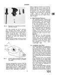
3. Raise the vehicle using either
a jack and stands or a vehicle ramp.
4. From below, cut and remove the heat shrink sleeve securing the two accumulator
switch harnesses together.
5. Remove the anti-back-out plate from the rear of the multi-plug.
6. Note the positions of the connections in the multi-plug and remove the seal. Remove
the appropriate connector pins from the plug using Service Tool JD 137.
NOTE: Further details on pin removal can be found in BookS, Section 86, Page 86A-4ofthe
XJ6 2.9/2.6 Service Manual.
7. Thoroughly clean the accumulator switch assembly ensuring that the surrounding
area is free of all dirt and grit etc.
•
8. Remove the leaking/faulty switch from the accumulator body and discard.
Refitting:
1. Fit the new switch assembly to the accumulator body and tighten to the correct torque
i.e. 31-39 Nm.
CAUTION: DURING THIS OPERATION IT IS IMPERATIVE THAT NO FOREIGN BODIES ARE
ALLOWED TO ENTER THE ACCUMULATOR.
2. Position the harness pins through the anti-back-out plate and seal. Fully seat the pins
into their appropriate positions in the multi-plug See Fig 1.
•
Y/R Y/8
JLM 1563
J51·81.7
B/K
8/K
•
FIG 1
Jaguar Cars Limited 2005
ScanFile 2002 v6.0 - Computer: SCAN004 - User: ADMIN - Date/Time: 28/08/02 1:03:47 PM - Page: 463/470
PAGE: BATCH
SHEET3 of 6
SERVICE BULLETIN JO 01/88
•
3. Fully seat the sea l and anti-back-out plate in the multi-plug socket .
4. Secure the two switch harnesses together using su itable insulating tape.
5. Feed the accumulator harness up through the engine bay to locate the socket.
NOTE: Ensure that the plug and socket are clean and free of any contam ination before
connecting them together.
6. Lower the vehicle and connect RS25 plug and socket. Secure with a tie strap.
7. Start the engine and allow the hydraulic system to pressurise.
8. Check for any leaks.
9. Check/top up the power hydraulic fluid reservoir.
Repair Operation Number: Lower Pressure Switch- 66.30.11
Charge Switch
- 66.30.12
•
Labour Allowance : 66.30.11 - 0.5hr
66.30.12 - 0.5hr
ITEM: 08
70 JURID 518 FRONT AND REAR BRAKE PADS
XJ6 2.9/3.6
A revised brake lining material known as Jurid 518 was introduced on Production
progressively from VIN 533084 and as 100% fit from VIN 533361 .
These pads can be identified by the wording JURIO 518 printed on the top face of the pad
material.
Part Numbers will be advised in a Parts Information Bulletin when sufficient stocks are
available.
•
ITEM: 09
76
DOOR CLOSURE
XJ6 2.9/3.6
The Service network has identified a condition where during the closure operation, a door
latch may not fully engage causing the door to rebound open. This is caused by either
maladjustment of the lock linkage or contact between the door assembly and aperture
fittings which impedes closure.
This condition mainly affects rear door operation but as the adjustment procedure is
identical for both front and rear doors, repair methods are included for both.
This Bulletin Item details in Section One a method for checking if free play exists at the
exterior handle. Section Two provides a procedure for setting the lock linkage and Section
Three identifies a number of potential contact areas which can affect closure.
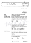
SECTION ONE
•
1. Ensure the sill link is in the fully unlocked position and the latch claw is in a partial
closed position (A Fig 1).
2. Place a finger into the striker slot (B Fig 1) where the upper part will make contact with
the lock pawl (C Fig 1).
Jaguar Cars Limited 2005
ScanFile 2002 v6.0 - Computer: SCAN004 - User: ADMIN - Date/Time: 28/08/02 1:03:47 PM - Page: 464/470
PAGE: BATCH
3. Use the other hand to check the exterior handle for free play. If set correctly the pawl
wil l remain stationary during the initial movement of the handle, i.e. 1-2mm. Should
pawl movement be identified move to Section Two.
NOTE: Excessive play at the exterior handle can also cause door closure problems and will
necessitate adjustment. Refer to Section Two and adjust to attain the correct setting.
•
SECTION TWO
1. Remove the door veneer panel and upper and lower trim pads. Remove the taped
plastic moulding from the door inner panel to allow access to the lock assembly.
2. Release the locknut at the top of the handle link barrel nut (D Fig 1).
. , · 3. Place a finger into the striker slot to contact the pawl and with the other hand rotate the
barrel nut in the direction of the arrow (E Fig 1) until the pawl ceases to move. Rotate
the nut one further full turn or until free play is identified at the exterior handle.
· ·· 4. Secure the locknut using two spanners and recheck the free play.
..
:
•
:5. Refit all trim etc.
.
•
-.,
FIG 1
SECTION THREE
Where door closure problems are identified and checks have shown that the lock linkage
is set correctly, the door should be examined initially for profile and adjusted as necessary.
Should a closure problem exist after profile setting and it is established that the striker is
correctly set, the aperture should be examined for contact marking.
Potential contact areas and corrective actions are detailed below:
'1f
1. Draught welt flange. Should hard contact be noted, where possible the flange should
be dressed carefully inboard to effect clearance.
2. Tread plate contact. Where this is identified, remove the tread plate and using a
suitable file remove sufficient material from the tread plate to obtain clearance.
Jaguar Cars Limited 2005
•
ScanFile 2002 v6.0 - Computer: SCAN004 - User: ADMIN - Date/Time: 28/08/02 1:03:48 PM - Page: 465/470
PAGE: BATCH
SERVICE BULLETIN JD 01/88
•
SHEET4of6
3. Door seal wrinkling. This usually occurs atthe top of the "C" post and inhibits rear door
closure. To rectify fit a new seal.
Repair time allowances:
Front Door Exterior Handle Linkage Adjustment
Operation No: 76-37-10- Time allowance 0.55 hrs.
Rear Door Exterior Handle Linkage Adjustment
Operation No: 76-37-11 -Time allowance 0.55 hrs.
NOTE: Any repair time allowance for Section Three items are covered by normal warranty
times where a component is replaced.
.·.
ITEM: 10
86
•
TIME CLOCK
XJ6 2.9/3.6
During July 1987 a new type of time clock was progressively introduced onto XJ6·with
100% fitment from VIN 521288. Visually the old and new clock look identical. The
difference between the two being the method of control; the old unit obtained all its power
and data signals from the central processor whereas the new unit generates its own timing
s1gnals, hence 1ts name being a 'stand alone clock'
To ascertain which type of clock is fitted to a vehicle an inspection of connector RB/LB30
must be undertaken. The wire/pin details are as follows:
PIN3
PIN7
PINS
PIN9
PIN 12
PIN 13
PIN14
PIN 15
•
CPU CONTROLLED
STAND ALONE CLOCK
Slate/Yellow
Slate/White
Slate
Blue
White
Slate/Brown
Slate/Yellow
Orange/Brown
White
Slate/Brown
Brown/Green
Orange/Brown
It should also be noted that PIN 14 on the bulkhead harness side of the connector should
have a brown link wire going directly to the bulkhead positive terminal post. If this wire is
not connected then the clock will lose its memory when the ignition is switched off.
JOS Software Issue DBC 4004 covers the CPU controlled clock and not the stand alone
clock, this will be incorporated into a future softwaH-r&e-+'re~IIGea.as~e~.-------------
ITEM: 11
86
HIGH MOUNTED STOP LAMP
XJS/S.III V12/XJ6 2.9 & 3.6
(NOT USA/CANADA)
It has become apparent that Dealers have been approached by owners requesting the
fitment of production build USA/Canadian specification high mounted stop lamp
assemblies.
•
Will Dealers please note that the fitment of such lamps in both the U.K. and European
markets is strictly governed by legislation.
· · ·.. ; ·
High mounted stop lamp assemblies as fitted to USA/Canadian specification vehicles do
not comply with this legislation and SHOULD NOT BE RTTED.
··
·
. ..
Jaguar Cars Limited 2005
ScanFile 2002 v6.0 - Computer: SCAN004 - User: ADMIN - Date/Time: 28/08/02 1:03:48 PM - Page: 466/470
PAGE: BATCH
ITEM: 12
86
XJ62.9/3.6
FUSES/FUSE BOXES
Revised fuse box and failure modules have been introduced into production from VIN
531170. The fuse ratings and colour codes are given on the following charts.
•
Right Hand Side Fuse Box
Fuse
No.
1.
;;:·-
..
Fuse
Colour
Code
Value
Circuit
Light blue
15A
Right-hand front door: window, door guard lamp and
mirrors if driver's door.
Light blue
15A
'•
2.
Door lock control, luggage compartment lock, petrol
filler flap.
~,.v,3•
<:. ••· •.•
4.
"'"·.
5:-
Yellow
20A
Right-hand air conditioning (wherefitted)/heaterfan.
Light blue
15A
Right-hand main beam headlamp.
- Tan
6.
Yellow
Yellow
8.
9. "' · '': Tan,
Red or
,., :;; h:
'·
-~'C",Y,ellow
·., .+
I,_,
I I •
•
t,.
' w ,'
o • L~ ,
. • ··.-·.
.
......
~..
.
5A
Right-hand front lamps (side/side marker, direction
indicators and repeater).
20A
Heated rear screen, luggage compartment lamp, electric
aerial, heated door mirrors, rear quarter reading lamp
(R.H. [where fitted]).
10A
Right-hand rear lamps (stop, reverse, direction indicators
and fog [where fitted]).
20A
Front and rear cigar 1ighters (where fitted).
5 A,
10Aor
20A
Electric Accessories.
20A
Radio, sun roof, heated door locks (where fitted), glove
compartment lamp, map light, interior headrest lamps,
'state' illumination.
15A
Cooling fan, air conditioning compressor clutch (where
fitted), under bonnet lamps.
•
·'
11.
Light blue
12.
Violet
3A
•
Right-hand rear lamps (tail, number plate and side
marker).
~ ····
13.
14.
. Ligth blue
Red
15A
Right-hand rear door, window, door guard lamp.
10A
Right-hand dip headlamp, fog lamp (where fitted).
·'··
•
Jaguar Cars Limited 2005
ScanFile 2002 v6.0 - Computer: SCAN004 - User: ADMIN - Date/Time: 28/08/02 1:03:48 PM - Page: 467/470
PAGE: BATCH
SHEET 5 of 6
SERVICE BULLETIN JD 01/88
__.
left-Hand Side Fuse Box
Fuse
No.
Fuse
Colour
Code
Value
CtrcUJt
1.
Light blue
15A
Left-hand front door: window, door guard lamo and
mirrors if driver's door.
2.
Violet
3A
3.
Yellow
20A
Left-hand air conditioning {where fitted)/ heaterfan.
4.
Light blue
15A
Left-hand main beam headlamp.
5.
Tan
.•
5A
~
~
..
Instrument pack.
Left-hand front lamps {side/side ma rker, di rection
indicators and repeaters) .
·'
'
•
•
6.
Violet
3A
Ride levelling {where fitted ), power brakes.
7.
Brown
7.5A
Left-hand rear lamps (stop, reverse, direction indicators
and fog [where fitted]) .
8.
Natural
(White)
25A
Right-hand seat movement (where fitted ) and seat
heater (where fitted).
9.
Tan,
Red or
Yel low
5A
lOA or
20A
Electric Accessories.
10.
Natural
(White)
25A
Left hand seat movements (where fitted). and seat
heater (where fitted).
11.
Yellow
20A
Windscreen wiper, horns.
12.
Violet
3A
13.
Light b lue
15A
Left-hand rear door, window, door guard lamp, fue l fil ler
f lap, rear quarter reading lamp {L.H. [where fitted]).
14.
Red
10A
Left-hand dip headlamp, fog lamp (where fitted) .
Left-hand rear lamps (tail, number plate and side
marker).
Centre Fuse Box
•
Fuse
No.
Fuse
Colour
Code
Value
Circuit
1.
Violet
3A
Lamp modules right-hand rear and left-hand front,
alternator control.
2.
Violet
3A
Lamp modules right-hand front and left-hand rear.
3.
Tan
5A
Speed control (where fitted }.
4.
Violet
3A
Power brakes, ride levelling {where fitted).
5.
Violet
3A
Cooling fan, heated washer jets.
6.
Violet
3A
Radio illumination, breather heater.
Jaguar Cars Limited 2005
ScanFile 2002 v6.0 - Computer: SCAN004 - User: ADMIN - Date/Time: 28/08/02 1:03:49 PM - Page: 468/470
PAGE: BATCH
ITEM: 13
85 aJN~RRANr(~coOES
~-
+
·~
XJ6 2.9/3.6
'·
..De~lers; twv.e reported isolated incidences of excessive quiescent battery drain caused by
tti~:,rnain central processor unit or;r_ide height level sensor. Unfortunately when
_.. s4~m_it;'ti_~ng the warraryty d .a im De_~Jers,h,ave..been uncertain as tp the codes to use.
-.either
-~
"'-·- ;.-
'
•_.')~·;--·~ ·
.
.-
'; · ~
~-~
rj-\,.:·-····:~-
!.
-~---'. •
•
c
, -~---• ,_.
•
•. • •
. . For:-ri9t! ~eight level sensor.:ex,i~~ing.cocfe.refereriFe ,7UHJ.sholJid be used.
To identify quiescent drain caused by the main CPU, "Central Processor Unit Malfunction"
has been allocated to 4th-digit code ~Y~~;~n_Seetio~;~7B.· Therefore when submitting claims
please quote 7BLY. · · -- ·
· · · · · ·
··
· ·
·
.,_; :
·--~
I
:
·.··,
ITEM: 14
~--~ :
.l
•.
i'
·; ,· ~
t_
S.lll V121XJS V12/XJ6 3.6
•-- .
.-:::. ,..._ •
, •
'-.,;
• -
'': ,T.-Q_.prqvi_d.e aqr;ess to th.~ cppnec:tor on the cylinder: blo.d ( heater it has been re-positioned
in the radiator bottor:n hose. The heater.cable .is now fitted prior to shipment and strapped
as indicated by-Fig 1 XJ6 3~6 and Fig 2 S.lll V12 and XJS V12.
-~
.
•
_. · r
-• nrJlismodificatjon-l'l'\s,beenintroduc.ed f~om Engine Nos:
.~P. sa268
.r. S..IIIV12
;: .: ,,); •.,n· .. :_ 8$"55~54
- XJS V12
) 0··r. ~ ~,
'
·~';,';1
1
9DP 133250 ,.;_-- XJ6 3.6
: · ·~;· _J~;i(i--: _,L
q
.
--~ ~
~-··. · :f-.
~.~: ·~:. ; ~ · · ~·: ·, ~ }' -t1 __r
·~· ~-J ·,
FIG 1
.,
·'
:.: ··-·
~
-( . ::-" -•./
.....
•
.. "
• ~
i
"1.,
h
:v_.;_::.
.
•'
-~-
.-_ :::-
'
' • j '' •
; • ·_
•
..
'
-~
.Ji:'-'
t •·.Ji~.
' -~/j
l r.-:··. ; t· ;_",;·!"!
·, I
~-- ~- !
t
:.
:_"i 't '
"'
...
·- ~ ~ ~
'·. )~. c
-~
'
~
_;
)
·~
··.
'
•
>
Jaguar Cars Limited 2005
ScanFile 2002 v6.0 - Computer: SCAN004 - User: ADMIN - Date/Time: 28/08/02 1:03:49 PM - Page: 469/470
PAGE: BATCH
SERVICE BULLETIN JD 01/88
•
SHEET 6 of 6
ITEM: 15
86
CHLORIDE DRY CHARGED BATTERY COMMISSIONING
re
Investigations i r;t()prcimatu battelyf~illure :arT xJet;Hidrfde: re'placeir,ent batteiies"\ti~rt
NOS: DAC 4120,' DBC3 f35 and OAC4545t fl;ave em(;ih sized 'the need to corri'rn VS"sicrn th;~se
units in accordance with the rrii{rli.ifactui~ers rrrshtY.l'i oiis. Failure to do s·O'w~ll,:esufi'ii1-the
battery not achieving a~u!1. 1 ~t~t~ 91 ~~ar,9.~- i_~_ ~.~-rx!c~ :..F.u_U ,co,~r:n is~ioning ins~~-~~ti~n~ ~re
attached to Parts·suppl red r epla'Cemeht C;hionde ba'tt enes and are reproduceo -below for
reference.
·.
•.: · ··
a
·£.;- , "·::·<) ~
· f
..
d
~ r · ;::: "",·~ -~ ri:' _: ~ j !.;'..:~ f t-~
·
,-~
:
_
..
t t ; ·~..,,~~ (i1~
INSTRU'Cr'IONS- FOR cOf.tlMISS~-ONING DRY~CHARGED BA1TERIES: ,~ ... :: -':::!'i
(a) FILLING;
•
1. Remove vent plugs with each cell to the levels indicated in para 2 below wi th the
correct specific gravity acid as given in Table 1.
2. The level of . the filling-in acid should be 6mm above the separ:_ator~~.. q r where
applicable, flush with the tops of the ribs of the separator guards or ~o- ti1--e-1~v~ftR:~ea8
acid level indica~q_r bar at t!"le pottom of the filling tube.
.
.. . .
.
3. After a few minutes~ the ie'v~· of the ini~iar fiflirtg acic 'wiiPfall and' this1sh'OOl'cf.iflen1 be
restored by addirrg ri1ore ·~cid-'l,lt'ltil trie le~·ets _?oie_a~ait;_~~if.'p,a~~- 2 <::d)o'v~[·.:.-.:-: ~;r:t Pi
\~
.·~
~
c ,_..• ! g ~•.
.!"C' :
~ a;;
(b) PUTTING INTO SERVICE:
.
_
_.
1. After filling, the battery shau'ld .be ":ailowe·d-to stand for' ' appn:i~iniatf:H~/ 2D ~'rmtitites
before charging.
.
_
_. .
2. It is essential prior to fitment to give a battery a conditiortir;g charge.f8F approximately
4 hours at the charge rate of 6 amps to ensure peak pedormance. t:: -'::J-:'
3. Where batteries are stored for a period exceeding one vear in a tempc.~a-t~· climate of 3
months or more in temperatures greater than 30°C and/or humidity exceeding 80 %
they must be charged for 12 hours at the rate indicated.
4. Check the electrolyte levels after charging and adjust accordingly as instructions given
in section (a). When"1l-i.tfn g the battery to the vehicle ensure that it is properly secured
by the hold dowri ·device&:{hnt the terminals are lightly smeared with petroleum jelly
and that the cables a~e GQf~~Ctly_and securely COnnected to the battery terminals.
•
\
•.:.
..
'•.
;
1 • I
•
,
_:"'\
,:.
f
'/ ,
:.: L::'
0 ".'
;
.~
(c) BATTERY MAINTENANCE: - ·.
•
•
1. Keep the top of the batte;y : , :a clean and dry condition and the vent plugs securely
screwed or pushed tlome.:
.
- ·
--~ . . _
2. Keep termmals -and cc•mtectmris free from corrosion and coated witb petroleum jelly.
It is important to r.ote ·tt'fat overtopping can result in a ~et battery top which induces
corrosion.
,.
.
· :~
3. Maintain electrolyte to ·tbe- levels indicated. in section (·a). para 2 by the add ition of
distilled or de-ionised water.
.:--.~ --- ___
"
4. If batteries are used on applications without an engine driven charging unit, then
recharging should take place when the specific gravity drops to 1.220 (or 1.180 when
low gravity acid has been used for hot climates) until the specific gravity in all the cells
rises and remains constant for 3 hours. In any event such batteries should be put on a
monthly recharge schedule ~nsuring a fully charged condition is reached periodically.
5. Stored batteries should be ·recharged every 2 to 3 months (one to two months in hot
climates) until the fully ch~rged condition has been reached.
SAFETY PRECAUTIONS:
1. Take care when jiiling batteries with sulphuric acid. If splashed on skin or eyes f lush the
affected parts immediately with water.
2. During the charging of a b~ttery explosive gasses are given off. Keep the top well
ventilated and away from ·flames or sparks. _
3. Switch off the charger before disconnecting the cha;ger leads.
4. When putting the battery into service on a vehicle connect the earth lead last and when
removing the battery disconnect the earth learl first.
5. Keep the battery away from children.
Jaguar Cars Limited 2005
ScanFile 2002 v6.0 - Computer: SCAN004 - User: ADMIN - Date/Time: 28/08/02 1:03:50 PM - Page: 470/470
PAGE: BATCH
The specifi.c gravities shown b~lo.w ar~ qprrect~d to 25°C. To correct the specific gravity
r'eai:Ung fc>r other temperatures ·~pply t~e· C;;"Qtrectior:l formul~ ~b'own in the note on
. tempe:rature correction.·
·
·'
· '· ·· ·
·· · --' · · · ·· '
.
'··';··
..
.
,
;.·
IN CLiMATES
WITH
AIR TEMeERATU.RE
.
. .
. :,\ .
.
.
•.
-~-
·;~-It·· ~ ~,-_-:._~
~
SRECI.F.IC.GRAVf{;IES CORRECTED TO 25°C
:~-9i~.tifrn~'ii:~w.'
At End of Charge
!-~. ·~·
•· ' ·yeH¥ ·. ··- ·"
Normally bel'ow 32°C_
> .:
~ ·~
,«
,:"
•o; ' ;
M
0
'•'
••.
··-~,
·
~-
,:
•••
.:· r
• ·;,
~
'
•
~
,
'
··
1.230·-
1.270-1.290
1.240
1.240-1.260
~.
• • •o·O
Frequently above 32°C Low Gravity
'
··:
•
•
' •
M~xi mum P.ermissable Temperat_ure~()_f.
El·ectrolYteduririgiffla'rge .,,. '" ·'·· · · · · ·
.
'·
••,
'
.. ' ·• " . ... .
. •'
.'
..
'..
.
...
.· ~ ' '.,
Te!'lpera~ure
C~r~O,;'J"
. ;_ ;
.
.
...
' .
~-.
.". _;,
.
-
,.
-~
~-
Tg correct to 25°C,for eve.r:v 10°C hiQh~JS!Jb~rSI~ O,OQ7-l7:-IJOi[!t.~J.for eyery 1ooc lower add
·.
0;007T7.pointsfe.g: 1.2~7:.at 1~oc equals. t;2ao .at' 25oc: .. · ··..
. ··_.:)"_.-:
.? . ~?
:->~-
. ~ ..
!"
.l
.
•
....
.• .
•
>• •
ITEM: 16
XJS
XJS_rnod~\~ (from VIN 149730) are now fitted with aChlq.ride Pa!tery,P,art No. DAC 4545.
This:iine·o~rates an·int~gral vent ~ystern ellrr~inating'.tt:t~ _-p~e,v:i.eus v~n,ted cap and hold
down$lnil:fTQaccommodatethisbatterythefollowif'l.Q~9J!lP.o.pentsarealsointroduced:
··:,.:.·,··;:._
... !;·~
~!~··:·:~.:-:·~
·-'.:
"i·:--:.··:··:
,.·:""~-:"_'·:.··
Batter¥ Tray
B~ftety'CQver
Blittef¥'Tit;! Rods
B~tte'ryCiamp
PtiSft·iv~ Q.~tterv Lead .
. .• ·. -· .;_
V~Jif:'Pipe ~·:
.· .. ' · ..~·;. ·.:· ·.:·
:·
. '· ·.:: " • ...,.--•. 1·
BCC 9561
BCC9?64 .·
DAC 47~·, .
DAC 4121'.;.
DAC_5608.
00502
In conjunction a sla_
v e batt~ry syst~m.~,sirn.Uar to t.hat)J~~ for XJq m.qp~l~ has also been
intrc5duced arid hew!;fu_lty~ch·~rgec:f'~$#,~1)': is..t'fQY.IJit.t~d''to'all vehlcfes at the point of
despatch':
flinsuie.the''battery dra-ijjJs:t"'QJ)tlPB.min!iDIJfTldu:ri !'l9 theJransit.period, it has
beef'l-::necessar)t :-ld·'~eril~lce~~-ip fu_~~s.; ():6' .vet;.iql,~,~)h,tp~~,:.to.~e·~p.~ma rkets. Fuses
removed:'afe·as follows::. ' ·...; . . ......;-. ..
.. . ..
..
To
·_,_
a
•
:;· ~ ~ : .. . '· ,·· ;,: ..: .
Location
-'-0\<
1
1, 2, 3, 15
1i(passiv~ restraint)
18 (passive·i"$sthiintr '·,
;. .•.;,• ..
~··.. :
.
• .,::·:.
,.···~
,:·
~
.: ·J.
Maio tu~eQQ~.~ drive(~.footw~ll-component plate.
'·.·.'.}..!.·: ~~ ,...\...;'.;· ~:,;
~.J~.v-~·
..
·-.
·•·
..,.
•
-·
.•
:·:;.t ~
Disp,taced fuses wilt b~ pl~ce~ i_f.l ~_p_t~i.c::; bag anq ~q.r~Q..in the glov~J?ox. These should be
refitted'afF(OJ;
' o:: ' :. - .< · ·' .•.• ;y.::. · ·'· ..
. . .. , ... .. .
.
.
. ;:~ i;. ,._._~·:·~~<! ·i! ·:· "?
•
Jaguar Cars Limited 2005
ScanFile 2002 v6.0 - Computer: SCAN004 - User: ADMIN - Date/Time: 28/08/02 1:00:53 PM - Page: 61/470
PAGE: BATCH
Service Bulletin
JA~
DATE: DECEMBER 1989
SHEET:
1of4
RER
JD19/89
ITEM:89
AJ6ENGINES
26 WATER PUMPS-COOLANT LEAKS
•
A high percentage of returned water pumps, replaced under warranty for leaks, have been
tested and have been found fault free .
It is important that before condemning the water pump, other areas of the cooling system are
eliminated first, i.e.
1) The hose clips securing the hoses to the water pump and the thermostat
housing.
2) The thermostat housing joint.
ITEM:90
64 REAR SUSPENSION 'A' FRAME MOUNTING BUSHES
XJ6 2.9/3.6/4.0
Service Repair Operations are now available for renewing the rear suspension 'A' frame
mountingbushesonXJ6 2.9, 3.6 and4.01itremodels.
The following bush renewal procedure should be adopted:
•
Remove' A' Frame Mounting Bushes
Raise the vehicle on a ramp.
Ensure the vehicle is positioned on the ramp with one of the differential drive flange spider legs
lowermost, see Fig 1.
Remove the fuel pump mounting bracket to 'A' frame securing m 1ts.
Remove the 'A' frame to differential rear bracket securing bolts.
Remove the 'A' frame to differential front bracket inner securing nuts and bolts.
Place a jacking channel on the ramp bed and mount a suitable bottle jack on the jacking
channel. Align the channel and jack under the previously positioned lowermost differential
drive flange spider leg. Insert a suitable block of wood {approx. 25 x 50 x 1OOmm ( 1 x 2 x 4in))
between the jack and the differential drive flange spider leg, see Fig 1.
Operate the jack to just take up and support the axle assembly.
DO NOT overstress the differential drive flange and coupling with undue pressure.
•
NOTE: Ensure the axle assembly is only supported with the jack under the lowermost
differential drive flange spider leg. DO NOT support the axle by using a propeller shaft drive
flange spider leg as the drive flange coupling would almost certainly be overstressed .
Jaguar Cars Limited
Jaguar Cars Limited 2005
ScanFile 2002 v6.0 - Computer: SCAN004 - User: ADMIN - Date/Time: 28/08/02 1:00:54 PM - Page: 62/470
PAGE: BATCH
•
FIG 1.
Remove the' A' frame mounting bush to body and bracket to body securing bolts and remove
the mounting bush brackets.
Lower the jack approx. 25 mm ( 1in) to give improved access.
Remove the 'A' frame to differential front bracket, intermediate securing bolts. Remove the
'A' frame to differential front mounting bracket and tie rod, outer securing bolts.
•
NOTE: Ensure the outer securing bolt spacers remain in position (captive) in the differential
front bracket after the removal of the securing bolts.
Remove the 'A' frame to differential casing securing bolts, applying hand pressure to support
the 'A' frame whilst the final bolt is removed.
Remove the 'A' frame from the vehicle.
Position tool JD 143 on the bed of a hydraulic press.
Ensure the cut-out in the tool is uppermost.
Remove the nut and washer from tool JD 143-6 and fit the tool assembly on to the 'A' frame
mounting bush. Ensure the flats on the tool locate between the bush rebound stops. Fit and
tighten the nut and washer to hold the tool in position, see Fig 2.
u
•
.D 143-6
FIG2.
Jaguar Cars Limited 2005
•
ScanFile 2002 v6.0 - Computer: SCAN004 - User: ADMIN - Date/Time: 28/08/02 1:00:54 PM - Page: 63/470
PAGE: BATCH
SERVICE BULLETIN JD 19/89
•
SHEET 2of4
Position the 'A' frame mounting bush housing on to tool JD 143, ensuring that the weld nut
boss of the 'A' frame locates in the cut-out of the tool. Align the mounting bush with the
hydraulic press ram, then, keeping the 'A' frame level, operate the press to remove the bush.
Remove the 'A' frame assembly from the hydraulic press. Remove tool JD 143-6 from the
mounting bush by removing the nut and washer. Discard the bush.
If required, the other mounting bush can be removed in the same manner.
After removal of bush(es), refit the nut and washer to tool JD 143-6 then store the tool in a
safe place ready for future use.
Fit New' A' Frame Mounting Bushes
Invert the 'A ' frame. Position the mounting bush housing on to tool JD 143. Position the new
mounting bush, flange uppermost, on to the 'A' frame bush housing. Align the new bush to
set the centre line of the bush rebound stops with those of the opposite bush, see Fig 3 .
•
JSI-116~
FIG3.
NOTE: Bush to be within 5 degrees of position shown.
•
•
Place a suitable flat steel plate centrally on to the mounting bush. The steel plate should be
sufficiently large enough to cover the rubber flange of the new bush, see Fig 4 .
u
FIG4.
Jaguar Cars Limited 2005
ScanFile 2002 v6.0 - Computer: SCAN004 - User: ADMIN - Date/Time: 28/08/02 1:00:54 PM - Page: 64/470
PAGE: BATCH
Adjust the 'A' frame assembly to centralise the new bush and steel plate with the ram of the
hydraulic press. Keeping the 'A' frame level, operate the press to fully seat the new bush.
Remove the steel plate. Remove the 'A' frame assembly from the hydraulic press.
When the new bush(es) has been fitted, store the steel plate and tool JD 143 in a safe place
ready for future use.
•
Position the 'A' frame assembly at the correct location on the vehicle. Fit, but do not tighten,
the ·A' frame to differential casing securing bolts.
Align and seatthe fuel pump mounting bracket studs to the 'A' frame, then, fit and tighten the
securing nuts.
IMPORTANT: Ensure the fuel pump wiring remains clear of the 'A' frame clamping face.
Fit, but do not tighten, the 'A' frame to differential front bracket outer securing bolts. Ensure
the spacers, previously left in position in the differential front bracket, are in the correct
position before fitting the securing bolts.
Fit and tighten the 'A' frame to differential rear bracket securing bolts. Tighten the 'A' frame
to differential front bracket outer and intermediate securing bolts, inner securing nuts and
bolts and the 'A' frame to differential casing securing bolts.
Raise the bottle jack ram approx. 25mm { 1in) to seat the 'A' frame mounting bushes on to the
tapered body locations. Place the mounting bush outer brackets in position and fit, but do not
tighten, the mounting bush to body securing bolts.
Align the outer bracket to body securing bolt holes, fit and tighten the securing bolts and
finally tighten the mounting bush to body securing bolts.
•
NOTE: New self locking bolts should be used. DO NOT re-use old bolts.
Lower the bottle jack, remove the block of wood, bottle jack and jacking channel. Lower the
vehicle on the ramp.
The following Service Repair Operation numbers apply:
64.25.09 Rear Suspension 'A' Frame Mounting Bush, Vehicle Set-Renew 1.60 hrs.
64.25.1 0. Rear Suspension 'A' Frame Mounting Bush, One Side-Renew 1.35 hrs.
When making warranty claims, Complaint Code 5HB should be used using the appropriate
4th digit.
ITEM: 91
66 POWER STEERING I RIDE LEVEL SYSTEM RESERVOIR
XJ6 2. 9 I 3. 6 90 MY ONLY
•
A new power steering/ride level system reservoir, incorporating a revised filler neck and cap
design, has been introduced on XJ6 models from VIN 601983. The new reservoir is
identified by the filler cap having six semi-circular 'finger grip' indents equally spaced around
the outer diameter. compared with the four lugs used on the earlier design.
The new filler cap must not be used with the old type reservoir.
If H.M.S.O. fluid leakage from the reservoir/filler cap seal is experienced on 1990 MY
vehicles prior to VI N 601 983, an alternative cap seal available from Jaguar Parts Operations,
should be fitted. This seal is available under Part No. CCC 2 782 and should be fitted in
accordance with the procedure detailed below:
* Remove the filler cap from the reservoir and using a suitable implement, remove the seal
from behind the retaining flange, A Fig 1.
Jaguar Cars Limited 2005
•
ScanFile 2002 v6.0 - Computer: SCAN004 - User: ADMIN - Date/Time: 28/08/02 1:00:55 PM - Page: 65/470
PAGE: BATCH
•
SERVICE BULLETIN JD 19 I 89
SHEET3of4
A
»1-' 107
FIG 1
•
*
Discard the seal. Clean the cap and reservoir neck_
*
Locate the new seal in the cap, seating the seal against the retaining flange as shown in B
Fig 1. Do NOT locate the new seal behind the retaining flange.
•
Check the fluid level and top up as necessary .
*
Replace the filler cap.
Warranty claims should be submitted quoting Warranty Complaint Code 6FXZ and Repair
Operation No. 66 91 09. A labour allowance of 0 . 1 hrs. may be claimed.
ITEM: 92
76 ROOF PANEL RESONANT NOISE (BOOM)
XJ6 NON-SUNROOF VEHICLES ONLY
Resonant boom emanating from the roof panel (non-sunroof cars only) has been recognised
as affecting XJ6 cars fitted with headlinings manufactured using compressed felt as the
backing material.
•
To prevent further instances of this problem, a new 'moulded polyurethane' headlining has
been introduced on all non- sunroof cars built from VI N 5 95 794.
To address this problem on vehicles built prior to the above VIN, the following rectification
method should be applied:
IMPORTANT. This repair sl1ould be carried out after customer complaint onl·f.
a) Position front seats fully forward with the squabs fully reclined.
b) Detach and lower the headlining, allowing it to rest on the seats.
NOTE: It is not necessary to remove the headlining from the vehicle.
c) Affix the anti-resonance pads, Part No. BEC 9039- 3 required, per vehicle- to the inner
face of the roof panel; the positions are indicated in Fig 1.
•
Jaguar Cars Limited 2005
ScanFile 2002 v6.0 - Computer: SCAN004 - User: ADMIN - Date/Time: 28/08/02 1:00:55 PM - Page: 66/470
PAGE: BATCH
•
JSI-1159
FIG 1
NOTE: Although these pads are self-adhesive and magnetic, they should be firmly pressed
along their length on to the panel using a roller or wooded block to ensure full adhesion .
d) Refit the headlining and road test the vehicle for elimination of resonant boom.
Warranty Claims should be submitted quoting Complaint Code 9KAB, SBQ 76-91-45,
labour allowance of 1. 75 hrs.
•
ITEM:93
86 WATER TEMPERATURE SWITCH
XJ62.9/4.0 1990MY
Revised operation of the air conditioning/heater water temperature switch in conjunction
with circuitry changes to the electronic control module, have been incorporated at 1990
ModeiYear-VIN 594576.
The water temperature switch performs the following function:
If warm air is required and the coolant temperature is less than 30°C, the fans are switched
off. This avoids large amounts of cold air being blown into the car.
From 1990 MY, the operation of this switch has changed from normally open when the
coolant temperature is below 30 o C; to normally closed and open when the coolant is above
30°C.
•
Operation:
When the coolant is below 30°C, the switch is closed, thus supplying an earth to the ECU
(this will inhibit the fan operation, as for previous models).
When the coolant is above 30 °C, the switch will open and the ECU will see 5 Volts from its
own pull-up, now incorporated into the ECU, (this will allow the fans to operate normally).
PLEASE NOTE: The revised temperature switch and new electronic control module ARE
NOT interchangeable with previous parts.
Fault Analysis:
The old system inhibits the fan operation if either the temperature switch or the harness
become open circuit. With the new system, if the switch or the harness become open circuit,
the fans will continue to operate even if the coolant temperature is below 30° C.
Simi liar modifications to XJS and S.lll V 12 will be introduced in the near future. Introductory
VI N 'swill be advised in a future Service Bulletin.
Jaguar Cars Limited 2005
•
Ill
JA~
Service Bulletin
II
DATE: APRIL 1992
PAGE: 1 of 4
REF: JD 03/92
Owing to revised information received from Engineering, pages 11 of Service Bulletin
JD 01/92, 3/4 and 9/10 of Service Bulletin JD 02/92 are being re-issued and are provided at the end of this Bulletin, marked " *Issue 2* ".
Existing pages of the above should be removed and discarded to be replaced with the
revised version.
XJ6 3.2 & 4.0
ITEM: 20
03 ADDITIONAL REPAIR OPERATION TIME
The following Repair Operation Times are now available:
12.29.16 -
Cylinder Head Gasket Rear Blanking Plate Gasket
Renew -
1.40 Hrs
12.29.17 -
Cylinder Head Rear Blanking Plate
Renew -
1.40 Hrs
-
Please amend your Repair Operation Time Schedule accordingly.
No other Repair Times are affected.
XJ6/ XJS
ITEM: 21
10 BRAKE SYSTEM SERVICE RECOMMENDATIONS
With the introduction of new brake components on the above models, the brake
servicing recommendations have changed.
No routine replacement of system seals is necessary as the seals are designed to last
for the life of the vehicle.
The braking system must still be inspected for satisfactory operation and condition
at the regular service intervals.
Brake fluid to be renewed at 2 years or 30 000 miles (48 000 km) intervals, whichever
is the sooner. For North America only, 18 months or 30 000 miles (48 000 km).
Note:
Service Manuals will be up-dated at the next reprint.
Jaguar Cars Limited
Jaguar Cars Limited 2005
JA~
JD 03/92
ALL AJ6-ENGINED VEHICLES
ITEM: 22
26 WATER PUMPS
A revised water pump assembly has been introduced on AJ6 engines. The assembly
now has a gasket between the two halves, instead of RTV sealant as previously used.
The revised assembly is fftted from the following engine numbers:
3.2: 107696
4.0: 157275
The part number of the new assembly is EBC 8550 and replaces EBC 4437. The part
number of the gasket is EBC 9220.
Note:
THE GASKET CANNOT BE RETRO-FITTED TO RTV-SEALED WATER
PUMPS. IF A LEAK BETWEEN THE TWO HALVES IS APPARENT, THE OLD
STYLE PUMP ASSEMBLY MUST BE REPLACED BY EBC 8550.
When EBC 8550 has been fitted to an engine, the bolts securing the two halves together must be re-torqued to 21.5 Nm - 28.5 Nm, to overcome the possibility of
gasket relaxation.
XJ6 I XJ-S I 5.111
ITEM: 23
80 AIR CONDITIONING/HEATER MICROPROCESSOR
82
Refer to Service Bulletin JD 09/91, Item 62.
To improve the retention of the air conditioning/heater servo drive motor ICs (integrated circuits) secured to· the microprocessor unit heatsink, the supplier has now
changed the process to "Rivscrews".
This modification commenced during mid-November 1991 and replaced the previous bolt-type fixings.
Air conditioning/heater units fitted with revised microprocessors were progressively
introduced from VINs:
XJ6
659029
XJS
183501
S.lll
486299
XJ6
ITEM: 24
84 WINDSCREEN WIPER ARM AND BLADE
From VIN 657725, all XJ6vehicles have been fitted with a revised wiper arm and blade
assembly.
These new parts are interchangeable with cars built prior to this VIN, when changed
as an assembly only. Dimensional changes prevent the fitment of a mixed condition
of arm and blades.
Dealers are reminded that wiper blade replacement remains a part of the 7500 mile
(12000 km) service schedule for all vehicles.
2
Jaguar Cars Limited 2005
JD 03/92
JA~
XJS
ITEM: 25
86 STOP LIGHT FAILURE SENSOR MODULE- LOCATION
From VIN 179737 (92MY Facelift XJS), the stop light failure sensor module is located
in the boot of the vehicle, attached to the inside of the boot side reinforcement panel
(drainage channel) L.H. (Fig. 1).
FIG. 1
Prior to VIN 179737 (90MY XJS), the module is located beneath the centre console
veneer finisher, attached to a bracket in front of the stowage compartment (Fig. 2).
FIG. 2
3
Jaguar Cars Limited 2005
JO 03/92
JA~
XJ6
ITEM: 26
88 EXTERNAL SPEED SENSOR BRACKETS- IDENTIFICATION
Two external speed sensor brackets are available for use on XJ6 models. To avoid any
confusion, they are identified as follows:
Bracket
Part No
Description Of Use
CAC 9884
For all Drive Units prior to the introduction of EBC 9750 and EBC
9751 (no colour identification).
EBC 9820
For all Drive Units from the introduction of EBC 9750 and ESC 9751
{identified by a "spot" of blue paint).
4
Jaguar Cars Limited 2005
I
Service Bulletin
Date
Sheet
Bulletin
JUNE 1984
1 of 3
JD 06/84
ITEM 42
00
UK MARKET ONLY
DISTRIBUTION POLICY
In future, the Dealer distribution of this Bulletin will be confined to JAGUAR DAIMLER
Dealers only.
The circulation to Fleet and other recipients will remain unchanged.
Any non JAGUAR franchise holder who still has cause to require the Bulletins will be
reinstated to the circulation upon application:
Customer Service Department
Jaguar Cars Limited
Browns Lane
Alles ley
COVENTRY
CVS 9DR
ITEM 43
00
REPAIR OPERATION TIMES
SERIES 111/XJ-S
Would any franchise holders who have experienced difficulty in obtaining AKM 9038/83
- Series Ill Repair Operation Times, and AKM 4412/83 - XJ-S Repair Operation Times
from Unipart, please note that matters have been rectified and no further trouble should
be encountered.
Jaguar Cars Limited
Jaguar Cars Limited 2005
ITEM 44
03
SERIES Ill 3.4/4.2
SERIES Ill REPAIR OPERATION TIMES
There is an alteration to the Series Ill Repair Operation Times (AKM 9038/83) to three
operations concerning six cylinder vehicles.
The Operation Numbers are 82-50-53, 82-20-54, and 82-20-55. The alteration concerns
changing the entry in the Repair Time column from NAto NT::::::=, thus allowing the time
in the 5.3 column to be claimed.
The Repair Time columns for these three operations should now be altered to the following:
3.4
4 .2
5.3
82-20-53
NT:::.::::::=-
NT:::.:::::=-
1.90
82-20-54
NT~
NT:::.:::::=-
1.65
82-20-55
NT:::.:::::=-
NT:::=
1.60
No other Repair Times are affected.
ITEM 45
09
APPROVED LUBRICANTS
ALL
As part of our programme to evaluate and test oils, the following list of SYNTHETIC oils
has been given approval by Jaguar Cars:
PRODUCT NAME
SAE VISCOSITY RATING
Metul 300V
15w/50
Agip Sint 2000
10w/50
Mobil SHC
10w/ 50
20w/ 50
Mobil 1
10w/ 30
Shell Gemini
15w/ 40
Shell Gemini (Ouadro)
10w/ 40
Mobil 1 Rally Formula
5w/ 50
Generally, synthetic oils are superior in performance under extreme operating conditions
at higher engine temperatures.
Although all the above SYNTHETIC oils are approved by Jaguar Cars, it is essential that the
temperature chart detailed in the Owner's Handbook and Workshop Manual (reproduced
below for reference) is referred to. An oil with a viscosity rating which falls within the
ambient temperature scale which the vehicle is operated in MUST be used.
e.g.
10w/30 or 10w/ 40 MUST NOT be used if the ambient temperature EXCEEDS
16° C (60° F).
Jaguar Cars Limited 2005
Sheet 2 of 3
SERVICE BULLETIN JD 06/84
The above SYNTHETIC oils and normal mineral oils meeting BLS 22 .0L.02 are compatible.
As such, should synthetic oil not be available, it is acceptable to top up with a normal
mineral oil, providing it meets BLS 22.0L.02.
Engine Oil- Recommended S.A.E. Viscosity Range/Ambient Temperature Scale
ITEM 46
19
POOR HOT START (WARRANTY ADMINISTRATION)
V12 MODELS
Reference Service Bulletin JD 11/83 Item 72, please note the following warranty coding
should be utilised against this operation:
7G4A
ITEM 47
19
CRUISE CONTROL BRAKE PEDAL SWITCH
SERIES Ill
Further to modifications detailed in Service Bulletin JD 02/84 Item 12, the supplier of the
brake pedal switch, which disconnects the speed control system when the brake is applied,
has introduced additional quality improvements.
From Manufacturing Date Code A4 (A= January, 4 = 1984), switches to the latestcondition
have been introduced from Vehicle Identification Number:
381034
Parts Division stock is to the latest condition.
Jaguar Cars Limited 2005
ITEM 48
26
XJ12/XJ-S
LOW COOLANT PROBE
Further to Service Bulletin JD 10/83 Item 66, which detailed the method of relocating the
low coolant probe in the header tank to overcome the involuntary flashing of the warning
light, this Service Fix has now been incorporated on all production vehicles from the Vehicle
Identification Numbers quoted below. The low coolant probe will be situated in the header
tank.
384477- Saloon
11 5816 - XJ -S
ITEM 49
37
77 MM TRANSMISSION -5TH GEAR RETENTION
SERIES Ill XJ6
Several reports have been received of the 5th speed gear and synchromesh hub coming
adrift due to failure of the retaining circlip to secure the assembly to the main shaft.
Investigations have revealed the problem to be due to operator error in not ensuring that the
circlip was fully seated in its groove.
Assembly Instructions have been amended to ensure that circlip retention is correct.
This has been introduced at:
TRANSMISSION NO.
ENGINE NO.
0366880
8L 158819
ITEM 50
44
GM400 SUMP GASKET LEAKAGE
XJ12/XJ-S/LIMOUSINE
To overcome the problem of oil leakage from GM400 transmission sump gaskets, the
following modifications have been introduced:
1.
Thicker gauge material for the sump pan.
2.
:mproved gasket material.
These modifications were introduced on Transmission Numbers:
84ZU 4057
84ZD 1164
The first engines to have modified transmissions fitted were:
8S 28242 - XJ -S
7P 49806 - XJ 12 Saloon
The introduction point for Limousines will be given when it is available.
The part number of the new gasket will be given when parts are available.
Jaguar Cars Limited 2005
Sheet 3 of 3
SERVICE BULLETIN JD 06/84
ITEM 51
76
SERIES Ill
AIR EXTRACTOR NOISE
Rectification of rattles emanating from the flaps of the air extractor tray was detailed in
Service Bulletin JD 07/83 Item 49.
Self adhesive plastic caps, BAC 3859, are now available for use instead of the self adhesive
strips previously recommended.
NOTE: Plastic caps are packaged in strips of 56. When ordering one off BAC 3859, 56 caps
will be supplied, which is enough for 7 vehicles (2 caps per flap, 8 caps per vehicle).
BAC 3859 was introduced at Vehicle Identification Number:
376790
ITEM 52
79
REPAIR CONSUMABLES
SERIES 111/XJ·S/LIMOUSINE
Continuing the policy of evaluating consumable products for use on Jaguar vehicles, the
following products have been approved for service use, and are additional to products
previously approved.
NOTE: When using any of the products recommended by Service, reference should be
made to the appropriate data sheet sup pi ied by the manufacturer.
1~1 AUTOCOLOUR ANTI STONE RESISTANT PRIMER] Water based primers available
P955-3001
in one litre containers for use
with suction feed spray gun
or Schutz gun.
BERGER STANDOX STONE RESISTANT PRIMER
3M's BODY CAULKING 8568
Water
resistant
thumbing
compounds
for
sealing
openings in body panels.
DUNLOP SEMSTRIP 2208
]
3M's BOLTED PANEL SEALER 8574
J
Water resistant sealers for
jointing
between
bolted/
rivetted panels.
DUNLOP SEMSTRIP GP
3M's SUPER SEAM SEALER 8537
A brush on sealer ideal for
footwells and floor seams.
ITEM 53
84
SERIES Ill 6 CYLINDER MODELS
(NON HEAD LAMP WASH/WIPE)
WINDSCREEN WASHER PUMP
To improve the windscreen wash facility on Series Ill 6 cylinder non headlamp wash/wipe
models, a larger capacity washer reservoir incorporating a "Tudor" heavy duty pump
assembly has been introduced from Vehicle Identification Number:
385665
Jaguar Cars Limited 2005
Service Bulletin
Date
Sheet
Bulletin
JULY 1984
1 of2
JD07/84
ITEM 54
26
ALL MODELS
COOLING SYSTEM
Instances have been reported of sludge contamination in the cooling system resulting in
poor heater performance or overheating. Samples of this contaminant have been analysed
and identified as a phosphate based substance probably caused by the use of non approved
anti-freeze. Only anti-freeze recommended in the workshop manual (copy shown below)
should be used for topping-up and re-fill purposes.
RECOMMENDED ANTI-FREEZE
\
·u·
BP Type HS25 Bluecol
Union Carbide UT 184 or Unipart Universal, if these are not
available •. phosphate free anti-freeze conforming to specification BS 3150 or 3152 may be
used.
Concentration- UK and RHO export markets only 40% sp gr 1 .065.
In North America use Jaguar Part No. ZvW 244101.
All other markets 55% sp gr 1.074.
In territories where anti-freeze is unnecessary the cooling system must be filled with a
solution of Marston Corrosion Inhibitor Concentrate SQ36.
Always top-up the cooling system with recommended strength of anti-freeze or corrosion
inhibitor, NEVER with water only.
·
N.B. When investigating overheating problems on vehicles fitted with air conditioning, a
check should be made to ensure that there is no road debris trapped between the radiator
and the condenser.
ITEM 55
37
MANUAL GEARBOX
SERIES Ill XJ6
Several reports have been received of 77mm 5-speed gearboxes "jumping out of gear".
Sample gearboxes returned for investigation have been tested and found to be functioning
correctly. It is known that if the transmission tunnel cover plate or gear lever gaiter are
incorrectly fitted, the gear lever movement can be restricted to prevent the gears engaging
fully. If any manual XJ6 vehicles are encountered which are jumping out of gear or suffering
difficult gear engagement, then the centre console should be removed to check that the
gear lever movement is not restricted by either the gaiter or the cover plate before the
transmission is removed.
Jaguar Cars Limited
Jaguar Cars Limited 2005
ITEM 56
47
PROPS HAFT
XJ-S 3.6/XJ-SC 3.6
When fitting the propshaft into the Getrag manual gearbox, care must be taken not to
disturb the oil sealing plug (A) by pushing the propshaft too far into the gearbox (see
diagram). The only stop, when sliding the propshaft into the gearbox, is the sealing plug at
the bottom of the propshaft reverse spline and if any force is used the plug can be disturbed
and allow oil to leak out from the gearbox.
A
60/64 FRONT/REAR SHOCK ABSORBERS
SERIES Ill XJS
The supply of front and rear shock absorbers has been changed from Girting te Boge.
Front and rear Boge shock absort)ers were introduced on Series Ill saloons at VIN: 391800.
At present on XJS models only, front Boge units have been introduced and Girting rear units
are still fitted.
A further bulletin will be issued advising the introduction of rear Boge units on XJS models.
Boge shock absorbers can be identified by an all black paint finish which replaces the dark
blue/grey finish used by Girting, and are fully interchangable with the Girting unit.
Jaguar Cars Limited 2005
SERVICE BULLETIN JD 07/84
Sheet2 of2
ITEM 58
70
FRONT BRAKE DISC PROTECTION
XJS/S.III
Difficulties have been encountered in production concerning the fitment of brake disc
protection covers and anti-rust paper. This has resulted in the fitment being suspended from
the following VIN 's:
388191 - Series Ill
116764-XJS
When the protection covers and anti-rust paper are re-introduced, the introduction points
will be advised in a future Service Bulletin.
ITEM 59
76
ELECTRIC DOOR MIRROR
S.III/XJS HE
To improve the reliability of the electrical door mirror assembly, mirrors are now equipped
with a new 'Kienzle' motor unit.
Units to the latest condition being progressively introduced at VIN 's:
390466- Series Ill
117350 -XJS HE
\
ITEM 60
82
BLOWER FAN ASSEMBLIES
S.UI/XJS HE (AIR CON. MODELS ONLY)
To overcome noise/vibration problems experienced with the current blower fan units, new
fan assemblies incorporating 'Smiths' Motors have been re-introduced on air conditioned
models only from VIN's:
382821 -Saloon
115478 -XJS
For normal service replacement purposes the new 'Smiths' Motor will be supplied complete
with a balanced fan assembly, mounting bracket and link harness. Part No's:
JLM 232 -RH
JLM 233-LH
This kit may be used to service all previous fan assemblies incorporating either 'Smiths' or
'Delanair' type motors.
Should replacement of complete blower assemblies be required, units to the latest
condition are available under Part No's:
CAC 8710- RH
CAC 8711 -LH
Jaguar Cars Limited 2005
Service Bulletin
Date
Sheet
Service Bulletin
SEPTEMBER 1984
1 of 3
JD 09/84
ITEM 71
12
S.lll 4.2 XJ6
All Markets except North America, Australia,
Canada, Japan, Sweden, Switzerland
ENGINE STALL
Further to Service Bulletin JD 08/84 Item 65, isolated reports have been received of engine
stall/idle dip on vehicles not fitted with AIR CONDITIONING.
Such vehicles may be modified as detailed in JD 08/84 but terminal 6 (Fig. 3) need i~OT be
connected to the green/brown (GN) compressor feed (C Fig. 2) and should be taped back
into the harness.
ITEM 72
12
S.lll 4.2
EXCESSIVE OIL CONSUMPTION
A further modification has been introduced on 4.2 XK engines to improve engine oil
This modification concerns a new piston ring pack and was introduced at
engine number:
cor:~sumption.
8L 167619
Part numbers will be advised when stocks are available.
ITEM 73
12
EXHAUST VALVE GUIDES
S.lll XJ6
A modification has been made to the exhaust valve guide to overcome sticking valves. This
modification involves relieving the valve guide bore at the exhaust port end. This was
introduced at engine numbers:
8L 167200
8A 15507
7M 4927
4.2
3.4
Limo
New part numbers will be issued when stocks are available.
Jaguar Cars Limited
Jaguar Cars Limited 2005
ITEM 74
12
SPARK PLUGS
V12 HE ENGINES
Due to supply difficulties with the copper cored resistive spark plug recently introduced
(see JD 05/84 Item 39), it has been necessary to revert to the old spark plug in certain
markets for a limited period. Detailed below are the markets and Engine numbers affected:
All Markets except:
North America, Australia, Canada, Japan, Sweden, Switzerland.
XJ12
XJS
From 7P 50514 to 7P 50749
From as 29a99 to as 30614
ITEM 75
26
TOP WATER HOSE
XJS 3.6 & XJ-SC 3.6
Investigations into the failure of a top water hose, part number CAC 5100, have revealed
that the material at the centre of the hose was not fully cured. The suspect hoses have the
date code 13/a3 moulded into the outer covering of the hose, along the centre line.
It is essential that all vehicles are inspected and if found to have a top hose - CAC 5100
with a date code 13/a3 fitted, then the hose must be replaced.
This inspection is to be carried out during normal vehicle servicing.
NOTE: All vehicles produced after VI N 11a692 are assured and do not need checking.
ITEM 76
76
SUNROOF PANEL STICKING
S.lll
Investigations reveal that where sunroof sliding panels stick in a closed position, damage to
the sunmof motor can result. The sticking condition is caused by a white grease which is
smeared around the sunroof aperture to assist smooth panel operation. Under certain
conditions the grease becomes very sticky and causes the lid seal to stick to the aperture.
To ensure smooth sunroof operation this grease MUST BE COMPLETELY REMOVED.
If the sunroof subsequently fails to operate smoothly, a suitable alternative lubricant can
be applied.
The grease detailed above was deleted from new vehicles from VI N 396121.
Rectification
1.
2.
3.
4.
Remove sunroof panel as follows:
(a)
Fully open the sunroof.
(b)
Remove four screws from the front edge of the sliding panel.
(c)
Operate the sunroof towards a closed position at the same time lifting the
front of the sliding panel away from the undertray.
(d)
After full travel, lift the sliding panel clear by releasing from two clips at
the rear end.
Clean sunroof aperture and sliding panel seal THOROUGHLY using white spirit
SBP3 or a similar suitable solvent which will NOT damage T.P.A. Paint.
Apply lubricant seal if desired (See Note).
Refit lid.
Jaguar Cars Limited 2005
Sheet 2 of 3
SERVICE BULLETIN JD 09/84
Warranty claims for this rectification should be submitted using Code 9C9F, Labour
allowance= 0.45 hours.
Notes on Lubricants
In the absence of universally approved lubricants, it is permissible for Dealers to use a
proprietary silicone based lubricant. However it must be emphasised that, whilst fully cured
paint is not affected by silicone sprays, such sprays MUST NOT be discharged near vehicles
undergoirtg paint rectification or silicone cratering may result.
U.K. Approved Lubricants
1.
Hellerine:
Hellerman Electric
Pennycross Close
Pennycross
Plymouth
Devon PL2 3NX
Application: Smear lightly on to the rubber seal.
2.
A.O.T. Superlube:
A .O.T. Limited
lmmex House
Imperial Way
Watford
Herts.
Telephone Watford 33477
Application: Spray lightly on to seal. It is important to remove any spray from painted
surfaces or marking may result.
ITEM 77
82
ALL XJS MODELS
AIR CONDITIONING IN CAR SENSOR
To improve in car sensor response on XJS HE and XJ 3.6 models a Blown Aspiration
System similar to that currently fitted to Series Ill models, is shortly to be introduced.
Introduction vehicle identification numbers will be advised in a further Service Bulletin.
Should Distributors/Dealers receive customer complaints of a slow sensing action, i.e. the air
conditioning unit, irrespective of what automatic mode it is set at, blows either too hot or
too cold for a prolonged period before stabilizing the in car temperature, then vehicles may
be modified in accordance with the following procedures.
Parts required are as follows:
Part No.
CAC 8362
C15150/8
CAC 3398
Description
Aspirator Choke
Hose
Elbow Pipe
Oty. per Car
1
1
2 (RHO)
1 (LHD)
Please note that hose part number C15150/8 is supplied in a 1 metre (4Qin) length, however
this will require cutting to the following lengths for RHO and LHD applications:
RHO= 279.0 mm (11.0 in) 1 off
RHO= 38.0 mm ( 1.5 in) 1 off
LHD = 889.0 mm (35.0 in) 1 off
Jaguar Cars Limited 2005
Labour Allowances
RHO= 0.75 hrs
LHD = 1.55 hrs
Should be quoted utilising Warranty Code 8R4U
IN CAR SENSOR MODIFICATION RIGHT HAND DRIVE (RHO) REFERENCE FIG. I
1.
2.
3.
4.
5.
6.
7.
8.
Disconnect Battery.
Remove the passenger side underscuttle trim panel and glove box assembly.
Remove the in car sensor assembly and associated pipe work.
PLEASE NOTE: The existing in car sensor (E), foam tube (G) and rubber elbow (F)
should be retained when modifying both RHO and LHD conditions, all other
components removed may be discarded.
Also rubber elbow (F) should be shortened at the sensor connection end by 25.0mm
(l.Oin) for both RHO and LHD applications.
Utilizing the existing components referred to above and the new parts required,
pre-assemble as shown in Fig. 1. Locate the in car sensor harness connection (H)
through the foam tube (G) before connecting to the sensor (E). Using suitable
adhesive tape, secure the sensor (E) to the choke (D) and slide foam tube (G) into
position shown in Fig. I.
Relocate modified assembly into position ensuring that no kinks or twists are
evident in rubber hose sections (Band C).
Using a suitable plastic self locking ratchet strap, secure the lower rubber hose
section (B) to the side of the air conditioning/heater unit case, as per original
installation.
Replace under scuttle trim panel and glove box assembly.
Reconnect battery.
·
I
~ --
c:?
F--u
I
E
G
H
Jaguar Cars Limited 2005
JSI 271
SERVICE BULLETIN JD 09/84
Sheet 3 of 3
IN CAR SENSOR MODIFICATION LEFT HAND DRIVE (LHD) REFERENCE
Fig. 2 - Modified Hose Routing.
Fig. 3- Sensor Component Assembly.
1.
2.
3.
4.
5.
6.
7.
8.
Disconnect Battery.
Remove the driver and passenger side underscuttle trim panels.
Remove the instrument pack assembly and glove box compartment.
Carefully remove the existing choke assembly from the driver's side blower fan
ducting.
Cut off the plastic ratchet strap retaining the rubber hose to the air conditioning
unit case and remove the choke assembly from the hose.
Remove the sensor assembly, disconnect the sensor harness and disconnect assembly
from the rubber hose.
Cut off the surplus rubber hose protruding at both the driver's and passenger side.
Extreme care should be taken to ensure that the sensor harness at both ends is clear
before commencing cutting.
PLEASE NOTE: Due to the original rubber hose section being secured to the main
bulkhead harness and the securing points being inaccessible, the route of the original
rubber hose cannot be utilized.
The new rubber hose section (B) is to be routed forward of the bulkhead harness
following the space created by the shape of the facia crash roll as shown in Fig. 2.
For ease of fitment It 'is advised that the new rubber hose is fitted from the driver's
side.
.J-
-
]-----------------=--=-=--· -------------
FIG. 2
Jaguar Cars Limited 2005
9.
10.
11.
12.
13.
14.
With the rubber hose (B) in position, connect the hose to the driver's side blower
motor duct aperture utilizing metal elbow (A). Using a suitable plastic self locking
ratchet strap secure the rubber hose (B) to the main bulkhead Rarness as shown in
Fig. 2.
Locate the in car sensor harness connections (H) through the foam tube (G) and
connect to sensor (E). Connect sensor (E) to the new choke assembly (D) and
secure using suitable adhesive tape. Slide foam tube (G) into position shown in
Fig. 3.
Connect rubber elbow (F) to the sensor (E).
Connect choke/sensor assembly to hose (B) and fit to vehicle, ensuring that no kinks
or twists are present on hose (B).
Replace under scuttle trim panels, glove box compartment and instrument pack.
Reconnect battery.
FIG.3
Jaguar Cars Limited 2005
Service Bulletin
Date
Sheet
Bulletin
JANUARY 1985
1 of 3
JD.01/85
ITEM 01
12
OIL PRESSURE SWITCH
ALL MODELS
During investigations into oil leakage from the oil pressure switch, it has been noted that
non approved pressure switches are being used. Please note that Unipart switch GPS 117
IS NOT APPROVED for fitment on Jaguar vet"licles and must not be used as the hexagon
size prevents secure fitment in Jaguar applications.
The onl.v oil pressure switch specified and approved for use on current Jaguar vehicles is
· C 42200.
ITEM 02
26
COOLANT HEADER TANK
XJS 3 .6/XJ·SC 3.6
Following reports of coolant loss from the header tank f iller neck joint, all header tank s
are now pressure tested after stove enamelling. The solder specification has also been
improved to prevent any possibility of the solder melting during the stove enamell ing
process. Header tanks are quality assured from VIN 119730 and Parts stocks are all to the
latest condition.
Jaguar Cars Limited
Jaguar Cars Limited 2005
ITEM 03
26
S.lli/XJS HE
THERMOSTAT HOUSING GASKETS
To overcome isolated instances of coolant loss from the thermostat housing, new gaskets
have been introduced on 6 cyl (XK) and V12 engines. The new part numbers are detailed
below:
Model
XJ6 3.4, Limo
XJ6 4.2
XJ6 3.4, 4.2, Limo
XJ12, XJS HE
XJ12, XJS HE
Description
Thermostat Housing Gasket
Thermostat Housing Gasket
Water Outlet Pipe Gasket
Thermostat Cover Gasket LH
Thermostat Cover Gasket R H
Part No.
EAC 7044
EAC 7046
EAC 7045
EAC 7047
EAC 7048
The bolt t ightening torques are also revised to:
6 cyl (XK)
V12
23-28.5 Nm
10.8- 12.2 Nm
(17-21 lb/ ft)
(8-9 lb/ ft)
The improved gasket and revised tightening torques were introduced at the following
engine numbers:XJ6 3.4
Limo
XJ6 4.2
XJ12
XJS HE
8A 15616
7M 4974
8L 173271
7P 51620
8S 32778
ITEM 04
57
S.III/XJS
POWER ASSISTED STEERING RACK
Continual monitoring and examination of returned Power Assisted Steering racks has
resulted in the following improvements:
1.
To prevent rack bar contamination due to the use of spurious lubricants during
Service, extensive testing by Jaguar and Adwest has resulted in the deletion of the
rack damper grease nipple. Greasing of the rack damper during Service is NOT
necessary as initial greasing by the manufacturer is considered sufficient.
2.
To alleviate the possibility of scoring the rack bar with the steering alignment tool,
when checking the steering geometry, a deeper and chamfered centralising pin hole
has been introduced.
3.
A new tangential valve and torsion bar has been introduced.
These improvements have been implemented on steering racks built after date code 4L 0001
and were introduced progressively on to Jaguar production from VINS:
413000
120500
S.lll
XJS
Jaguar Cars Limited 2005
SERVICE BULLETIN JD.01/85
Sheet 2 of 3
ITEM 05
70
ALL MODELS
BRAKE BEDDING IN PROCEDURE
With the recent introduction of semi ·metallic brake linings, it is important that all Service
Personnel are aware of the optimum procedure for the 'bedding·in' of these linings. Details
are as follows:
In order to ensure optimum brake performance and refinement throughout the life of the
brake friction linings and brake discs, it is essential that a controlled brake bedding
procedure is undertaken during the early life of the friction linings.
The procedure used should ensure that the friction linings quickly achieve normal operating
conditions as a result of low energy applications, without being subjected to high energy
input levels.
The procedure recommended for the ·f irst 320 km (200 miles) is of deliberate, frequent light
application wherever possible, similar to that used during normal town driving. On open
road driving the above conditions have to be simulated. Try NOT to brake from speeds in
excess of 96 km/h (60 mph); reduce speed by short brake applications, i.e. 80-65 km/ h
(50-40 mph) at intervals of approximately 1.5 km ( 1 mile).
This procedure will ensure satisfactory brake lining/disc conditioning, and lead to optimum
brake I ife and performance.
ITEM 06
74
ALLOY WHEELS
S.III/XJS
Reports of difficulty in removing alloy wheels due to corrosion between the mating faces
of the wheel and the hub spigot has resulted in a greasing operation being introduced on
production.
The hub spigot bore of the wheel is now coated with Shell Retinax 'A' grease. This was
introduced at VIN Nos:
411159
119708
S.lll
XJS
ITEM 07
76
AUTOMATIC REAR SEAT BELTS
XJS (AUSTRALIA)
All XJS vehicles landed in Australia after January 1st 1985 will incorporate 3 point inertia
reel rear seat belts.
ITEM 08
82
AIR CONDITIONING SERVO UNIT
S.lll/ XJS HE/XJ·S 3.6/XJ-SC 3.6
Further to Service Bulletin JD.11/84 - Item 85 Reference Step 3. To prevent excessively
low pressure being generated in the air conditioning system under certain operating
conditions, the servo motor unit Rance override function has now been deleted. Units to
the modified condition were introduced from VINs:411931
120267
S.ll I
XJS HE/ XJ -S 3.6/ XJ-SC 3.6
Jaguar Cars Limited 2005
ITEM 09
82
RECEIVER DRIER
S.lll4.2 (AIR CON. MODELS ONLY)
To improve the efficiency of the Receiver Drier, the Drier has been repositioned to enable
maximum refrigerant flow through the internal pick-up pipe.
This repositioning has resulted in the sight glass now being on the left hand side and in the
vertical position. This change was introduced at VI N 412060.
When fitting replacement Receiver Drier Bottles on Series Ill 4.2 Models (prior to the above
VIN) the Receiver Drier should be fitted as described above.
The fitment of the Receiver Drier Bottle CAC 1881 on Series Ill 5.3/XJS HE and XJS 3.6
Models remains unchanged, i.e. the Drier mounted with the sight glass on the right hand side
and the sight glass angled approximately 15 degrees rearwards.
ITEM 10
86
DOOR POCKET WARNING LAMPS
S.III/JAGUAR VDP & SOVEREIGN ONLY
During the winter period, especially in markets where the ambient temperatures are
particularly severe, it is possible for the electric aeria I mast to freeze temporarily. I sola ted
incidences have been reported of the main circuit fuse blowing through the aerial operation
being impaired.
Should this occur it is possible for the door casing puddle lamps to illuminate with the doors
closed, and in some cases, due to the problem going unnoticed, can result in the battery
discharging when the vehicle is parked.
Through subsequent investigations, the cause has been traced to a feed back circuit
developing through the interior light circuit which is also protected by the same fuse link.
Fuse No. 3
Fuse No. 13
Main Fuse Box- LHD
Auxiliary Fuse Box- RHO
To prevent this involuntary illumination and possible battery discharge, modified bulkhead
harnesses incorporating diode protection on the interior light circuit will shortly be
introduced. Introductory VINs will be issued in a further Service Bulletin.
However should this problem be encountered on vehicles already in Service, the following
modification may be implemented:
Labour allowance
Complaint Code
0.45 hrs
7K7S
PARTS REOUI RED
Description
1 off Lucar Connector
1 off Lucar Connector
2 off Lucar Insulation Sleeve
1 off Diode
Part No.
GHF 2051
GHF 2060
GHF 2151
AAU 5034
Code (see Fig. 2)
A
B
c
D
Jaguar Cars Limited 2005
SERVICE BULLETIN JD.01/85
Sheet 3 of 3
MODIFICATION PROCEDURE
1.
2.
Disconnect the battery.
Remove the passenger side 'A' post lower trim panel to expose the lower bulkhead/
door harness (See Fig. 1). Passenger side RHO is shown, LHD is symmetrically
opposite.
\
\
FIG . 1
3.
4.
JS1 ·281
Locate the interior door switch purple/ white (PW} cable and cut.
Fit insulations sleeves (C, Fig. 2) and crimp/ solder Lucar connector (A and B,
Fig. 2) , to the purple/ white (PW) cable. Connect diode unit ( D, Fig. 2) in circuit
and strap or tape to the harness.
FIG. 2
5.
Refit the 'A' post lower trim panel and reconnect the battery.
Jaguar Cars Limited 2005
(
ITEM 11
86
IGNITION COl L
S.ll I 4.2
To improve the ignition performance on S.lll 4 .2 Models, a new Oucel!ier coil w ith ballast
resistor, together with a modified amplifier and engine harness have been introduced from
Engine No:8L 173271
Interchangeability with the previous ignition system is af fected.
Jaguar Cars Limited 2005
Service Bulletin
JA~
Date
Sheet
Bulletin
2nd ISSUE*
SEPTEMBER 1985
1 of 4
JD 09/85
ITEM: 62
12
S. III/XJ-S
OIL PRESSURE TRANSMITTER
Investigations into oil loss from the oil pressure transmitter, have
revealed that in the majority pf cases the leak is via the sealing
washer. To ensure that the washer seals correctly, the tightening torque
has been increased to 20.3 to 27.1 Nm (15-20 lbs/ft).
This change was introduced at the following engine numbers:
8L 1877 77 - 4. 2
8A 16096
7M 5084
8S 36329
7P 53368
- 3.4
- Limo
- XJS
- XJ12
ITEM: 63
12
ENGINE OIL COOLER PIPE
S.III 3.4/4.2
To eliminate the possibility of oil loss from the engine oil cooler hoses,
a new hose material has been introduced which has been designed to
withstand higher temperatures.
This has resulted in Part Number changes for the hoses:
CBC 1437 ~eplaces CA£ 4557
CBC 1438 replaces CAC 4558
These new hoses were introduced at VIN 432926
ITEM: 64
26
IDLER PULLEY ASSEMBLY
Vl2 MODELS
Following reports of fracturing of the idler pulley assembly, used for
tensioning the water pump drive belt on Vl2 engines, the material of the
pulley arm has been changed from aluminium to S.G. iron.
This modification has resulted in Part Number changes which will be
advised when the new parts are available.
The modification was introduced at engine numbers:
7P 53808 - S.III Vl2
8S 37231 - XJS Vl2
Jaguar Cars Limited
Jaguar Cars Limited 2005
*2nd ISSUE*
ITEM: 65
26
XJ-S 3.6/XJ-SC 3.6
THERMOSTAT
To improve heater output on XJS and XJ.SC 3.6 the cooling
thermostat has been changed from 82oc to 88°C.
The new Part Number will be advised when parts are available.
The new thermostat was introduced at Engine Number:
system
9DPAMA 102481
ITEM: 66
76
S. III
CENTRAL I.OCKING
Commencing with 1986 M.Y. a new electric locking system has been
introduced onto S.III vehicles, from VIN 428715 L.H.D. and 429455 R.H.D.
In general terms the main change from the previous system introduces
electric motor operation to the locks on all passenger doors and boot in
place of the electric solenoid operation used on earlier vehicles.
The whole system is .. activated by a control unit (DAC 3529), situated
inside the driver's door (Fig. 1).
OR
OR
OG
ll
OG
~·
OG
OG
6
Je&- Je•
KEY: 1 Door Locking Control Module (Driver)
2 Front Door Lock Motor (Passenger)
3 Rear Door Lock Motors
4 Boot Lock Motor
FIG. 1
The change in locking systems allows deletion of the lock relays, but
necessitate harness changes which will preclude conversion of existing
vehicles.
The driver's door control unit and the lock motors are mounted onto
brackets welded onto door rails in the same way as the lock solenoids.
The boot lock motor is mounted on the lid inner panel adjacent to the lock
mechanism.
This Bulletin lists component changes, setting procedures and fault
finding.
Jaguar Cars Limited 2005
Service Bulletin
JA~
Date
Sheet
Bulletin
SEPTEMBER 1985
1 of 4
JD 09/85
ITEM: 62
12
S.III/XJ-S
OIL PRESSURE TRANSMITTER
Investigations into oil loss from the oil pressure transmitter, have
revealed that in the majority of cases the leak is via the sealing
washer. To ensure that the washer seals correctly, the tightening torque
has been increased to 20.3 to 27.1 Nm (15-20 lbs/ft).
This change was introduced at the following engine numbers:
8L 187777 - 4.2
8A 16096
- 3.4
7M 5084
8S 36329
7P 53368
- Limo
- XJS
- XJ12
ITEM: 63
12
S.l!I 3.4/4.2
ENGINE OIL COOLER PIPE
To eliminate the possibility of oil loss from the engine oil cooler hoses,
a new hose material has been introduced which has been designed to
withstand higher temperatures.
This has resulted in Part Number changes for the hoses:
CBC 1437 replaces CAC 4557
CBC 1438 replaces CAC 4558
These new hoses were introduced at VIN 432926
ITEM: 64
26
Vl2 MODELS
lDLER PULLEY ASSEMBLY
Following reports of fracturing of the idler pulley assembly, used for
tensioning the water pump drive belt on Vl2 engines, the material of the
pulley arm has been changed from aluminium to S.G. iron.
This modification has resulted in Part Number changes which will be
advised when the new parts are available.
The modification was introduced at engine numbers:
7P 53808 - S.Ill Vl2
8S 37231 - XJS Vl2
Jaguar Cars Limited
Jaguar Cars Limited 2005
ITEM: 65
26
XJ-S 3.6/XJ-SC 3.6
THERMOSTAT
To improve heater output on XJS and XJ.SC 3.6 the cooling
thermostat has been changed from 82°C to 88°C.
The new Part Number will be advised when parts are available.
The new thermostat was introduced at Engine Number:
system
9DPAMA 102481
ITEM: 66
76
CENTRAL LOCKING
S. III
Commencing with 1986 M.Y. a new electric locking system has been
introduced onto S.III vehicles, from VIN 428715 L.H.D. and 429455 R.H.D.
In general terms the main change from the previous system introduces
electric motor operation to the locks on all passenger doors and boot in
place of the electric solenoid operation used on earlier vehicles.
The whole system is activated by a control unit (DAC 3529), situated
inside the driver's door (Fig. 1).
N
N
B
OR
OG
0
OR
0
o•
OG
OG
c
Jl&-le•
KEY: 1 Door Lock Control Module
2 Door/Boot Lock Motor
FIG. 1
The change in locking systems allows deletion of the lock relays, but
necessitate harness changes which will preclude conversion of existing
vehicles .
The driver's door control unit and the lock motors are mounted onto
brackets welded onto door rails in the same way as the lock solenoids.
The boot lock motor is mounted on the lid inner panel adjacent to the lock
mechanism.
This Bulletin lists component changes, setting procedures and fault
finding.
Jaguar Cars Limited 2005
SERVICE BULLETIN JD OSU85
SHEET 2 OF 4
COMPONENT CHANGES
Part No's
*1
*2
*3
*4
DAC 3529
DAC 3530
DAC 3609
DAC 3509
DAC 3504
DAC 3503
DAC 3572
DAC 3573
DAC 3571
DAC 3570
JLM 456
BAC 8554
SH 504051
FW 104T
BAC 5430
BAC 5431
BAC 4583
BAC 6728
BAC 6729
BAC 6727
BBC 6725
WF 600040
BBC 4580
Quanity per Vehicle
1
4
1
1
1
1
1
1
1
I
1
2
2
8
1
1
2
1
1
1
1
4
2
BAC 6476
DRC 1449/J
BBC 6724
4
10
2
AB 608081
CAC 1823
SH 604051
10
10
*1
*2
*3
*4
Except
Canada
Except
Jaguar
6
Description
Driver's Door Control Unit
Motor Unit
Boot Lock Link Lead
Bulkhead Harness RHD
Bulkhead Harness LHD
Bulkhead Harness LHD
Driver's Door Harness
Driver's Door Harness
Rearward Harness
Window Lift/Sunroof Harness
Lockset
Edge Nut (Boot Motor Bracket)
II
II
Setscrew
Washer - Mounting Brackets
Motor Mounting Bkt. Rear Door RH
II
LH
"
"
Link Motor to Latch Rear Door
Link Bell Crank to Latch Rear Door RH
11
11
LH
"
Link Boot Lock to Motor
Boot Motor Mounting Bracket
Spring Washer Mounting Bracket
Link Motor/Control Unit to Private
Lock - Front Door
Anti-Rattle Sleeve Rear Door
Grommet - Doors and Boot
Mounting Bracket-Motor/Control Unit
Front Door
Self Tapping Screw - Mounting Brackets
Insert Washer - Mounting Brackets
Setscrew - Mounting Brackets.
Canada
only
Jaguar Sovereign, VDP or Daimler
Sovereign, VDP and Daimler
SERVICE REPLACEMENT OF CENTRAL LOCKING CONTROL UNIT- DRIVER'S DOOR
1. Remove the door trim casing (Service Manual Operation 76-74~01)
2. With the door glass in the fully closed position, remove the adhesive
tape securing the control unit harness to the door interior, and
disconnect the control unit block connector from the door harness.
3 .. Remove the two setscrews securing the control unit assembly to the
bracket on the intrusion member, release the locking link (BBC 4580)
from the unit and remove the unit from the door.
4. Separate the control unit (DAC 3529) from the mounting bracket (BBC
6724) by removing the two self tapping screws.
5. To fit a new control unit reverse operations 2 to 4.
Do not fully
tighten the setscrews at this stage.
Jaguar Cars Limited 2005
SETTING PROCEDURE - DRIVER'S DOOR ONLY
1. Remove the 'A' Post lower trim panel, driver's side. (Service Manual
Operation 76-13-22).
2. Locate the door harness multiplug connector within the 'A' post with
orange/red and orange/green leads. Disconnect the connector.
3. Connect a test lamp across the connector terminals on the door harness
side (1 Fig. 2).
JSH 20
FIG.2
4
Set the outer door lock to full closed position
5. Set the door lock inner flap tu full locked po sition
6. Move the control unit by hand fully toward s the lock assembly, then
carefully move the unit slowly in the opposite direction until the test
light flashes momentarily.
The
unit
should
now be
positioned
correctly, tighten the setscrews (1 Fig. 3) .
,
FIG. 3
.
._
'
I,
JSi L1)
Jaguar Cars Limited 2005
SHEET 3 OF 4
SERVICE BULLETIN JD 08/BG
7. To check the setting move the door lock inner flap slowly to the unlock
position.
If the setting is correct the lamp will flash momentarily
just before the flap reaches full travel.
When the flap is moved back
towards the lock position, the lamp will flash again just before the
flap reaches full travel.
8. Disconnect the test lamp and reconnect the harness block connector
9. Operate the outer door handle to release the latch
10. Close the door and recheck the operation of all doors using the key in
the driver's door lock.
--11. Refit trim panels to 'A' post and door.
CAUTION Should it be necessary to connect an independant battery feed to
the control unit whilst in situ, the following connections must be
observed:
Positive feed to purple wire
Negative feed to black wire.
A wrong connection can destroy the control unit and it is recommended that
this operation is carried out with the unit removed from the vehicle.
SERVICE REPLACEMENT OF CENTRAL LOCK MOTOR UNIT FRONT AND REAR PASSENGER DOORS.
1
2
3
4
5
Remove door trim casing (76-74-01 Front Door)
(76-34-04 Rear Door)
With the door glass in the fully closed position disconnect the door
lock motor block connector -from the door harness. NOTE it may be
necessary to remove the plastic strap from around the harness for
access.
Remove two setscrews securing the lock motor assembly to the mounting
plate on the intrusion member, release the locking link (BBC 4580 Front
Door, BAC 4583 Rear Door), from the motor and r emove the motor assembly
from the door.
Separate the motor from its mounting bracket (BBC 6724 Front Door, BAC
5430/31 Rear Door) by removing two self tapping screws.
To fit a new motor unit reverse operations 2 to 4.
Do not fully
tighten the setscrews at this sta&e·
SETTING PROCEDURE - FRONT PASSENGER DOOR LOCK MOTOR UNIT
1
2
3
4
Set the door lock to the full closed position.
Slide the lock motor assembly towards the door lockface to take up all
free movement. Tighten the setscrews (1 Fig. 4)
Operate the exterior door handle. Close the door.
Check the setting by operating with the key from the driver's door.
Jaguar Cars Limited 2005
JS: t..')A
SETTING PROCEDURE - REAR DOOR LOCK MOTOR UNIT
1
2
3
4
Set the door outer lock to the full closed ~osition
Slide the lock motor assembly away from the door lockface to take up
all free movement. Tighten the setscrews (1 Fig. 4).
Operate the exterior door handle. Close the door
Check the setting by operating with the key from the driver's door.
SERVICE REPLACEMENT - BOOT LID LOCK MOTOR UNIT
1
2
3
4
Disconnect the lock motor block connector from the boot lid harness.
Remove the two setscrews securing the lock motor assembly to the boot
lid inner pa nel.
Release the locking link . (BBC 6727) from the motor
and remove the motor assembly from the boot lid.
Separate the motor from its mounting bracket (BBC 6725).
To fit a new boot lock reverse operations 1 to 3. Do not fully tighten
the setscrews at this stage.
SETTING PROCEDURES - BOOT LID LOCK MOTOR UNIT
1
2
3
Ensure that latch (BBC 3283) is in the unlocked position.
Slide the motor assembly towards the latch to take up all free
movement. Tighten the setscrews (1 Fig . 5).
Close the boot lid and check the setting by locking with the ke y from
the driver's door.
FIG.S
Jaguar Cars Limited 2005
SHEET 4 OF 4
SERVICE BULLETIN JD 09/85
FAULT FINDING
All Locks Inoperative
1
2
3
4
Check the fuse, mounted above the passenger's side fuse box.
Fuse intact - Check feed to 'A' post block connector at purple wire.
Feed established - check feed to control unit at the block connector
inside the door (See cautionary note)
Feed established - Reconnect the connector inside the door, connect a
test lamp across the door harness connector located within the 'A' post
as previously described and operate the door lock.
If the lamp does
not light momentarily change the control unit.
Passenger Door Motor or Boot Motor Inoperative
1
2
Check feed through system at block connectors at positions shown
(Fig. 2)
If a feed is established at the motor block connector, change the motor.
Dealers carrying out warranty repairs using operations detailed in this
Bulletin must refer to the relevant R.O.T. listed below.
Number
86-25-46
86-25-47
86-25-48
86-25-49
86-25-51
86-25-52
86-25-53
86-80-03
86-80-04
Time
0.55
0.50
0.50
0.35
0.40
0.35
0.25
0.85
0.65
Description
Front Passenger Door Lock Motor - Renew
Rear Door Lock Motor - Renew
Rear Door Lock Motor Bracket - Renew
Boot Lid Lock Motor - Renew
Front Passenger Door Lock Motor - Adjust
Rear Door Lock Motor - Adjust
Boot Lid Lock Motor - Adjust
Door Lock Control Module - Renew
Door Lock Control Module - Adjust
ITEM: 67
86
CENTRAL HIGH MOUNTED STOP LAMP
S.III/XJ-S Vl2 (NAS ONLY)
To meet current legislative requirements USA/Canadian specification S.III
and XJS Vl2 Models are now equipped with a central high mounted stop lamp
introduced at YIN's:
434936 - S.III
125881 - XJS Vl2
The new lamp is mounted on the heated rear screen assembly,
operation controlled through the existing stop lamp circuit.
Illumination is provided by 4 x 5 watt capless bulbs.
and
its
ITEM: 68
86
MERLIN ELECTRIC AERIAL
S.III
.To improve electric aerial performance and reliability, a new Merlin
aerial assembly incorporating a
'permanent magnet motor'
has been
introduced from VIN 430929.
Interchangeability with the previous installation is affected.
A further Service Bulletin will be issued detailing parts and fitting
procedures required for replacement purposes as and when parts stock is
confirmed.
Jaguar Cars Limited 2005
ITEM: 69
86
ALTERNATOR
XJ-S Vl2
A revised Al33-75 Amp alternator and alternator harness have been
introduced on XJS Vl2 models from VIN 124308.
The revised alternator incorporates a single eyelet connector which
replaces the previous Lucar terminals.
For introduction details on S.III Air Conditioned models JD 04/85 Item 30
refers.
ITEM: 70
88
FUEL GAUGE
S.III
Incidents of fuel gauge needles sticking have been found to be due to a
foul condition existing between the needle and dial face cut-out. To
overcome this problem the dial face cut-out has been enlarged with effect
from supplier date code 19.85.
The date code can be located on the label adhered to the instrument case.
Jaguar Cars Limited 2005
Service Bulletin
JA~
Date:
Sheet:
Bulletin:
MAY 1986
1 of 3
JD 05/86
ITEM: 34
12
TORQUE CONVERTER DRIVE PLATE
S. III XJ6
An improved full diameter drive plate has been introduced on 3.4 and 4.2
engines to overcome complaints of drive plate noise.
The new part number
EAC 8973 was introduced at the following engine numbers:
BA 16666 - 3.4
BL 207464 - 4.2
ITEM: 35
26
COOLANT PRESSURE CAP
S. II I/XJS
To prevent con t amination of the coolant pressure cap seal during initial
coolant fill, Barrs Leak pellets are now used in place of Barrs Leak
solutic,n.
These pellets, which are inserted into the bottom hose during
vehicle build, were introduced at VINs:
454031- S.TJI
131685 - XJS
ITEM: 36
44
TRANSMISSION INHIBITOR SWITCH
S.III 4.2
Instances of vehic.lf' failure to start in either Park or Neutral plus
failure of the Reverse light: fun<·tion, have resulted in transmissi on
inhibitor svitch DAC 4155 being replaced.
Following investigation of warranty returned units, a signi f icantly high
proportion have been confirmed satisfactory.
Howevet·, close examination
showed that in the majority of cases there are indentations in the switch
body, possibly due to overtightening of the fixing bolt.
Any subsequent
repositioning for adjustment purposes only has a temporary effect, as the
switch is liable to move.
In doing so the fixing washer again positions
itself in the indentation.
Jaguar Cars Limited .
Jaguar Cars Limited 2005
To overcome this problem the fixing washer size has been increased,
together with the addition of a shake proof washer, Torque Figure 16.5 to
18.5 lbf ins.
Production fit to the modified condition commenced at VlN: 453381.
If a problem is encountered in service prior to the abo"Ve VIN, and the
switch contact operation is coinfirmed satisfactory, then the following
procedure should be implemented.
Note:- If the indentation marl< on the
original switch is very severe then the switch should be renewed.
1) Remove the
washer.
inhibitor swi t.ch fixing nut and retain.
Check indentation mark.
2) Fit
Discard the plain
a new plain and shake proof washer t0 the following
dimensions and rPplace the fixin g nut, do not tighten.
Plain Washer
Shakeproof Washer
Outside
Diameter
Intetnal Bore
Diameter
12.5 mm
9.0 mm
5.3 mm
5.3 mm
nominal
Thickness
1. 0 nun
0.5 mm
3) Adjust the inhibitor switch as detailed in Service Bulletin JD 08/85
Item 61, and tighten fixing nut to torque of 16.5 to 18.5 lhf ins.
4) If
the operation of either thl:' inhibit or reverse 1 ight function is
still incorrect, loosen the fixing nut and adjust the switch until the
correct position is obtained, and re-tighten.
ITEM: 37
70
BRAKE FAULT DIAGNOSIS
ALL MODELS
To enable complaints, particularly of noise or brake pull, to be
accurately diagnosed and repaired, the following Bullet in item has been
prepared.
It is important to clearly identify and establish the actual complaint.
a) Judder - is accompanied by pedal pulsation
b) Brake rumble/noise
this complaint normally occurs when braking
heavily from high speed; because of the frequency of the vibrations
felt in the car, it is sometimes confused with brake judder.
c) Brake pull - the vehicle has a tendency to pull to the right or left
when the brakes are applied.
d) Brake squeak - occurs when braking at low speed or when coming to rest.
Jaguar Cars Limited 2005
SERVICE BULLETIN JD 05/86
JUDDER
* 2nd ISSUE*
SHEET 2 of 3
Note: This condition will usually exist i f
the
variation
in
thickness
of
each
individual disc exceeds O.Olmm (0.0004 in).
Grooved discs are not detrimental to the
operation of the brakes.
CARRY OUT A SHORT
ROAD TEST
I
COMPLAINT
SEE TEST FOR
CONFIRMED - - - N O - - - - - RUMBLE/HARSHNESS
I
I
YES
TEST FOR
FRONT OR REAR
To check the rear discs - do not exceed 40
km/hr (25 mph) and apply the handbrake. I f
the judder is from the rear discs, a
pulsation through the handbrake l ever will
be felt.
RENEW DISCS/PADS
AS NECESSARY
NOTE:
On
higher
mileage
vehicles
any
tendency for brake judder will be excited by
wear
in
the
suspension
joints,
e.g.
upper / lower ball joints, wishbone bushes.
BRAKE PULL
I
This condition is sometimes confused with
the tendency of certain vehicles to follow
the camber of the road.
ENSURE CORRECT
TYRE PRESSURES
I
ENSURE CORRECT
STEERING GEOMETRY
I
DEGLAZE PADS
AND DISCS
l
CHANGE FRONT ROAD
WHEELS SIDE TO SIDE
Jaguar Cars Limited 2005
*2nd ISSUE*
BRAKE RUMBLE
HARSHNESS
I
Remove all brake dust debris and lightly
emery the disc and friction pads.
CLEAN DISCS/PADS
RENEW DISC/PADS
BRAKE SQUEAK
SQUEAL
NOTE: Squeak/squeal is generated by the
accumulation of brake pad debris.
DO NOT
replace pads.
I
CLEAN DISCS/PADS
Remove all brake dust debris and lightly
emery the disc and friction pads.
WARNING: SOME BRAKE LINING DUST MAY CONTAIN ASBESTOS WHICH, IF INHALED, CAN
DAMAGE YOUR HEALTH.
ALWAYS USE A VACUUM BRUSH TO REMOVE DRY BRAKE LINING
DUST. NEVER USE AN AIR LINE.
ITEM: 38
86
S.III Vl2/XJS Vl2
SPARK PLUGS
Following Service Bulletin JD 03/86 Item 28, which advised introduction of
NGK BR7 EFS spark plugs in specific markets on Vl2, a revised Champion
spark plug has now been introduced in the remaining markets to overcome a
possible cold fouling condition from the following VINs:-.
326520 - S.III Vl2
105048 - XJS Vl2
Model
Engine Intro No.
Old Part No.
New Part No.
Vl2
USA
Australia
Canada
Japan
EAC 8914
Champion RSSC
EAC 9186
Champion RS9YC
7P 55854
8S 42817
Vl2
All Models
except
USA
Australia
Canada
Japan
EAC 8914
Champion RSSC
EAC 8554
NGK BR7 EFS
8S 41339
7P 55272
Please note: Any warranty claims resulting from use of non-approved spark
plugs will be rejected.
Jaguar Cars Limited 2005
SERVICE BULLETIN JD 05/86
SHEET 3 of 3'
ITEM: 39
86
SUNROOF MOTOR ASSEMBLY
S. III
Various internal design modifications have been incorporated into the
current sunroof motor assembly to improve the performance of the motor.
Production fitment commenced at VIN: 449846.
Further improvements to the sliding roof panel adjustment, together with a
modified seal, are to be introduced shortly and will he announced in a
future Service Bulletin.
1016F
Jaguar Cars Limited 2005