1
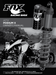
2.5 PODIUM-X ATV 2.0 PODIUMSHOCK RC2 AFTERMARKET OWNER’S MANUAL FACTORY SERIES OWNER’S MANUAL CONTENTS CONGRATULATIONS .................................................................................................................................. 3 CONSUMER SAFTEY ................................................................................................................................... 3 UNDERSTAND THE ATV 2.0 PODIUM RC2 ............................................................................................... 4 INSTALLING YOUR SHOCK ........................................................................................................................ 5 MEASURING AND SETTING RIDER SAG ................................................................................................... 8 DUAL RATE SPRING ................................................................................................................................. 10 ADJUSTING SPRING CROSSOVER ....................................................................................................... 11 TUNING THE ATV 2.0 PODIUM RC2 ......................................................................................................... 13 REBOUND ADJUST .................................................................................................................................... 13 DUAL SPEED COMPRESSION (DSC) ADJUST ....................................................................................... 14 TUNING NOTES ........................................................................................................................................ 15 MAINTENANCE ......................................................................................................................................... 16 REBUILD / SERVICE INTERVALS ............................................................................................................ 16 WARRANTY ............................................................................................................................................... 16 SERVICE .................................................................................................................................................... 16 Reference print standards 604-00-300 rev A 605-00-118-revC Pg. 2 CONGRATULATIONS Thank you for choosing the FOX ATV 2.0 PODIUM RC2 shock absorber for your ATV. In doing so we believe you have chosen the finest suspension products in the world. FOX shocks have been designed, tested and assembled in the United States for more than 35 years. As a consumer and supporter of FOX products, you need to be aware of the importance of setting up your shocks correctly to ensure maximum performance. This manual provides step-by-step instructions on how to set-up and maintain your shocks. It is a good idea to keep your proof of purchase with this manual and refer to it for service and warranty issues. This manual does not contain step-by-step shock rebuild instructions. FOX recommends that this only be carried out by an authorized FOX service center. CONSUMER SAFETY WARNING: Driving a ATV can be dangerous and can result in death or serious injury. Take your responsibility for yourself and others seriously, and heed the following safety tips: - Keep your vehicle and its suspension systems in optimal working condition. - Always wear protective clothing, eye protection and a helmet. - Know your limits and drive within them! The FOX ATV 2.0 PODIUM RC2 shock contains a high pressure nitrogen charge. The shock should only be opened by an authorized FOX technician. WARNING: Opening a nitrogen pressurized shock can be dangerous and can result in serious injury or death. NEVER attempt to disassemble the damper of your ATV 2.0 PODIUM RC2 shock. Do not puncture or incinerate the shock absorber or damper portion. Always wear eye protection when installing or adjusting your shock absorber. 605-00-118-revC Pg. 3 UNDERSTANDING THE ATV PODIUM RC2 FOX ATV 2.0 PODIUM RC2 shock absorbers set the industry standard for performance and durability. Equipped with external dual speed compression (DSC) and rebound adjusters, as well as spring preload and crossover location adjustments (dual spring only). Inside the PODIUM RC2 is a high-performance, velocity-sensitive, shimmed damping system. FOX PODIUM dampers contain high pressure nitrogen gas and FOX high viscosity index shock oil separated by an Internal Floating Piston. This helps to ensure consistent, fade-free damping in most riding conditions. DAMPING PISTON & VALVING REBOUND ADJUSTER BEARING ASSEMBLY SHAFT OIL EXTERNAL SPACER METERING ROD BODY BODY CAP INTERNAL SPACER BUMPER BODY CAP OIL EYELET NITROGEN CHAMBER HOSE (DSC) DUAL SPEED COMPRESSION ADJUSTER (IFP) INTERNAL FLOATING PISTON NITROGEN FILLER VALVE CAP (DO NOT REMOVE) ATV 2.0 PODIUM RC2 shocks are built using 6061-T6 aluminum for light weight and strength. The heat treated steel chrome plated damper shaft is super-finished for low friction and long seal life. All of the seals and wipers are engineered specifically for the ATV 2.0 PODIUM RC2. The body and reservoir are Genuine Kashima coated for reduced friction and long seal life. 605-00-118-revC Pg. 4 INSTALLING YOUR SHOCK Your shock absorber should come supplied with the correct o-rings, reducer set and reservoir mounting kit to mount the shock correctly to your vehicle. WARNING: Contact FOX if these reducers do not fit correctly. Correct shock mounting is critical for correct operation and for your safety. DO NOT REMOVE NITROGEN FILL VALVE WARNING: DO NOT REMOVE RESERVOIR NITROGEN FILLER CAP OR ATTEMPT TO CHANGE NITROGEN PRESSURE. DAMAGE TO SHOCK ABSORBER CAN OCCUR. The 2.0 PODIUM RC2 shock absorbers are equipped with rebound adjust and compression adjust low speed and high speed, both rebound and compression settings are preset in the middle of the adjustment range. But it is recommended that you check the settings by counting the number of clicks in clockwise until adjuster stops. Back the adjuster out the same number of clicks you turned the adjuster in. Note these settings in TUNING NOTES Section. STEP 1 Place the ATV on work stand. STEP 2 Follow the procedures outlined in your service manual, remove the stock shock from the ATV. Retaining the original mounting hardware, as they will be required to mount the 2.0 Podium RC2. 605-00-118-revC Pg. 5 STEP 3 Install the 2.0 Podium RC2 into the upper and lower mounts following the assembly procedures and torque values outlined in your ATV service manual. DSC ADJUSTER STEP 4 Install Reservoir Mounting bracket on ATV. Orient the reservoir to allow easy access to the DSC adjuster. Torque bolts to the specification listed in vehicle's service manual. STEP 5 Secure hose with zip-ties to prevent any damage from hot or moveable parts. Some vehicles may require additional hose protection. Ensure all hardware is torqued to the manufacturer’s specifications. 605-00-118-revC Pg. 6 Full extension measuring points. STEP 6 Position floor jack under vehicle so that when the vehicle is raised both front and rear wheels come off the ground at the same time. Raise vehicle until both wheels would be able to rotate with a little drag. Measure and note the distances at the front and rear measuring points. STEP 7 Lower the ATV to the ground. Measure and set rider sag as described in next section. Full Extension – Ride Height = SAG 605-00-118-revC Pg. 7 MEASURING AND SETTING RIDER SAG To get the best performance out of your 2.0 PODIUM RC2, it is necessary to adjust the vehicles ride-height or “sag”. Sag is how much the shocks compress — or sag — when you sit on your ATV. As a general rule, your vehicle’s rear sag should be 45%–65% of full wheel travel. There are many factors that will influence your sag setting and ride height preference, including tire diameter, terrain and riding style. Use the following procedure to accurately measure and set the correct ride-height (sag) for your ATV. (Measuring assistance will be required) STEP 1 Position the bike on a flat surface and clear of any obstacles. STEP 2 Place pieces of cardboard under each wheel. As the suspension is compressed, the front wheels move outward. This is called “scrub.” Placing the cardboard under the wheels allows the suspension to move more freely. STEP 3 While wearing your normal riding gear, mount the ATV and stand in your normal riding position with both hands on the bars. STEP 4 Aggressively bounce up and down on the quad several times and allow the quad to settle. STEP 5 Have the assistant push down on the front end of the ATV. While the suspension is compressed turn the handle bars full left and full right then straighten handle bars and release the front suspension. Bounce a couple more times. STEP 6 Gently assume your seated riding position. 605-00-118-revC Pg. 8 Measure from the ground to the bottom of the frame just below front motor mount. Measure from the ground to the bottom of the frame just ahead of the rear foot peg. STEP 7 While still seated on the ATV, have the assistant measure the vertical distance from the ground to the bottom of the frame, under the front motor mount (front frame height). Then measure the vertical distance from the ground to the bottom of the frame just ahead of the rear foot peg (rear frame height). RECOMMENDED FRAME HEIGHT GUIDE LINES TERRAIN/ RIDING DISCIPLINE MOTOCROSS CROSS COUNTRY WORCS DESERT SUPERMOTO FRONT TIRE DIAMETER REAR TIRE DIAMETER FRONT FRAME HEIGHT REAR FRAME HEIGHT 20" 21" 21" 23" 19" 18" 20" 20" 22" 18" 7 1/4" 7 3/4" 8" 9 1/4" 5 3/4" 7" 7 1/2" 7 3/4" 9" 5 1/2" STEP 8 If your ATV is sitting too low in the rear, increase the rear spring preload on the 2.0 PODIUM RC2. Follow the procedures outlined previously and repeat all the steps above until you reach the desired ride height setting. NOTE: YOUR SAG WILL NEED TO BE SET BEFORE SETTING CROSSOVER POINT ON DUAL RATE SPRINGS. 605-00-118-revC Pg. 9 DUAL RATE SPRING Your shock will be fitted with a single spring or dual springs, depending on your particular application. To maximize performance, different swing-arm and linkage combinations require different springs. The springs that come on your Podium RC2 are customized for your weight, riding style and terrain. 2.50 ID THRUST CROSSOVER SPRING RING COUPLER WASHER PRELOAD RING TENDER SPRING COUPLER GUIDE DUAL RATE SPRING FORMULA Example 600 LBS TENDER and 325LBS MAIN =210LBS Combined Rate 605-00-118-revC 2.25 ID THRUST WASHER MAIN SPRING SPRING RETAINER 𝟏 = 𝑪𝑶𝑴𝑩𝑰𝑵𝑬𝑫 𝑹𝑨𝑻𝑬 𝟏 𝟏 ! !+! ! 𝑻𝑬𝑵𝑫𝑬𝑹 𝑴𝑨𝑰𝑵 𝟏 = 𝟐𝟏𝟎 𝟏 𝟏 ! !+! ! 𝟔𝟎𝟎 𝟑𝟐𝟓 𝒍𝒃𝒔 Pg. 10 ADJUSTING SPRING CROSSOVER (DUAL SPRING ONLY) The spring crossover point is an important tuning parameter. A softer initial spring rate offers improved traction and hook-up while a higher spring rate deep into travel helps to resist bottoming on jump landings. As a rough guideline, the spring crossover point should be as deep into travel as possible without experiencing excessive bottoming. The crossover point is defined as a percentage of the total shock travel. The factory setting for the spring crossover point is 55 percent. This means that a 5.2 inch travel shock would have the crossover point at 2.86 inches (5.2 inches x 0.55) into the shock travel. In order to calculate your spring crossover ring placement, you need to know four important pieces of information: 1. 2. 3. 4. Metal-to-metal shock travel in inches (measure before spring installation). Main spring rate (lb-in) - marked on spring (see Below). Tender spring rate (lb-in) - marked on spring (see Below). Desired crossover point (as a percentage). The shock travel is the exposed length of the shaft (including the bump stop) when the shock is fully extended. It may be easiest to measure before you install the shock SHOCK TRAVEL EXTERNAL SPACERS SETTING THE CROSSOVER POINT (shock has been removed from vehicle for display purposes only) Some shocks use external spacers below the bump stop to limit travel. Do not include the spacer length as part of the travel. The crossover point is a tunable parameter. It should be between 45 and 65 percent. 1.004” SPRING IDENTIFICATION Tender Spring Main Spring 605-00-118-revC 0275-250-600 = 2.75” Long x 2.50” ID x 600 lbs. 0800-225-325 = 8.00” Long x 2.25” ID x 325 lbs. Pg. 11 Use the following formula to calculate crossover ring placement: Crossover Ring Placement = Shaft Travel (in.) x Crossover Point x Spring Correction Factor EXAMPLE • A 5.2-inch travel shock with a 600 lbs. tender spring and a 325 lbs. main spring. • The crossover point is set at 55 percent. • From the table above, the spring correction factor is 0.351. • From the above formula, the crossover ring placement value is 5.2 x 0.55 x 0.351 = 1.004 inches. IN THE ABOVE EXAMPLE, 55 PERCENT IS WRITTEN AS 0.55. NOTE: BE SURE TO TIGHTEN CROSSOVER RINGS AFTER SETTING CROSSOVER POINT WITH FLAT BLADE SCREW DRIVE AND A HAMMER. CALL 1.800.FOX.SHOX to get spring recommendations for your application and weight. 605-00-118-revC Pg. 12 TUNING THE 2.0 PODIUM RC2 SPRING FORCE At this point you have set the sag of your vehicle by adjusting the spring preload. Your spring force should be near its optimal setting. If you feel that the rear of the vehicle is too low as you are riding, increase the spring preload. If the vehicle is too high, decrease the spring preload. NOTE: NEVER INCREASE SPRING PRELOAD MORE THAN ½”. IF YOU NEED MORE SPRING FORCE GO TO THE NEXT HIGHER SPRING RATE. IF YOU NEED TO DECREASE SPRING PRELOAD TO THE POINT WHERE THE SPRING IS LOOSE WHEN THE VEHICLE IS ON A STAND AND THE SHOCK IS FULLY EXTENDED, IT IS NECESSARY TO OBTAIN A LOWER RATE SPRING. CROSSOVER POINT (DUAL SPRING ONLY) The crossover point should be between 45% and 65% of travel, the default setting is 55%. If you want to increase bottoming resistance decrease the cross over point to 45%. (The crossover ring will move closer to the spring coupler). If you are not bottoming and want to decrease bottoming resistance, increase the crossover point towards 65%. (The crossover ring will move away from the spring coupler). NOTE: SETTING THE CROSSOVER POINT OUTSIDE THE RECOMMENDED RANGE OF (45% TO 65%) MAY RESULT IN SPRING COIL BIND AND DAMAGE TO THE SHOCK AND OR SPRINGS. REBOUND ADJUST Rebound Adjuster The Rebound Adjust feature on your FLOAT 3 PODIUM RC2 shocks gives you the ability to externally adjust the shock rebound damping. Adjustments are made by turning Rebound Adjuster using a quarter or a small flat-bladed screwdriver to turn adjuster on the Clevis located on the end of the shock absorber. For slower rebound, turn the knob/screw clockwise. The rebound adjuster has about 20 clicks of adjustment. The factory setting is 12 clicks out. The performance of the shock at this setting is close to the performance of the non-adjustable shock and is a good all-around setting. The rebound damping affects how quickly the shock extends (rebounds). This adjustment affects how quickly the wheel will rebound when travelling through a series of large bumps and how quickly the front end responds in the corner. The optimum rebound setting is usually found with the minimum damping required to give acceptable control. Excessive rebound damping will typically be felt as the suspension "packing." This can often be seen or felt as the vehicle travels through a series of similar-sized, successive bumps. It works well for the first two or three bumps and then bottoms hard on the third or fourth. This is because the shock has not rebounded quickly enough, and the shock "packs" into compression 605-00-118-revC Pg. 13 DUAL-SPEED COMPRESSION (DSC) ADJUST The FOX DSC valve is standard on 2.0 PODIUM RC2 shocks and gives you the ability to externally adjust the damping. The DSC has about 24 clicks of low-speed adjustment and about 22 clicks of high-speed adjustment. The factory setting is 12 / 12. The performance of the shock at this setting is close to the performance of the nonadjustable shock and is a good all-around setting. The DSC valve gives the driver the ability to tune the shock for different terrain / personal preference on either side of this setting (softer or stiffer). LOW-SPEED COMPRESSION (LSC) ADJUST FOX DSC VALVE PERFORMANCE Low-Speed Adjuster dialed full soft to full firm Hi-Speed Adjuster held constant at 10 Clicks 0 0 20 40 60 80 100 120 140 Force (lbf) -100 -200 -300 -400 LSC Adjuster -500 Velocity (in/s) LSC (LOW-SPEED COMPRESSION) ADJUSTMENT The LSC is adjusted using a dime or flat-blade screwdriver in the middle of the adjuster. More damping = stiffer = clockwise LSC primarily affects the compression damping during slow suspension movements such as G-outs or smooth jump landings. It also affects ride comfort of the vehicle. Choose a LSC setting that gives good body control anti-roll in corners, without causing excessive harshness or loss of front end traction. The graph above shows the typical range of adjustability for the LSC adjuster from full-firm to full-soft with the HSC adjuster held constant at 10 clicks out. FOX DSC VALVE PERFORMANCE Low-Speed Adjuster held constant at 10 Clicks Hi-Speed Adjuster dialed full soft to full firm 0 0 20 40 60 80 100 120 140 -100 Force (lbf) -200 -300 -400 -500 -600 HSC Adjuster Velocity (in/s) HSC (HIGH-SPEED COMPRESSION) ADJUSTMENT The HSC is adjusted using a 17 mm socket More damping = stiffer = clockwise The HSC adjuster affects the compression damping during medium-to-fast suspension movements such as steep jump faces, harsh flat landings and aggressive whoops. The goal is to run as little high-speed compression damping as possible without bottoming. The graph above shows the typical range of adjustability for the HSC adjuster from full-firm to full-soft with the LSC adjuster held constant at 10 clicks: 605-00-118-revC Pg. 14 TUNING NOTES SAG ÷ Full Extension = SAG% DATE 605-00-118-revC COMMENTS FULL RIDE EXTENSION -‐-‐-‐ HEIGHT = SAG = == X-‐OVER DIST. X-‐OVER % LSC ADJ HSC ADJ REB ADJ Pg. 15 MAINTENANCE PROPER INSPECTION AND MAINTENANCE IS ESSENTIAL TO MAINTAIN THE PERFORMANCE AND RELIABILITY OF YOUR SHOCK ABSORBERS. It is important to keep the shock absorbers clean and free of residue. This will add to main seal life. When cleaning the vehicle avoid using a high-pressure washer near the seals as this could drive debris inside the shock. Ideally the shocks should be clean around the adjusters when changing the damping setting. A small blast of contact cleaner or brake cleaner before making adjustments will keep these parts clean and operating smoothly for years. REBUILD / SERVICE INTERVALS Just like the oil in your car engine, the oil in your shock absorber breaks down over time and must be replaced. The service interval depends on how frequently and severely the vehicle is driven. For optimum performance racing applications the shocks may require rebuilding every 10-20 hours of use. In non-racing environments to keep your shocks performing at optimum performance we recommend at least every 100200 hrs. of use. WARNING: Shock rebuilds take specialist knowledge and tools. It is essential that this is performed by an authorized FOX technician or service center. WARRANTY All FOX products have a one-year warranty on defects in materials or workmanship. Please view the full warranty terms and conditions at www.ridefox.com/ps-warranty or contact a representative at 1.800.FOX.SHOX (1.800.369.7469). SERVICE Contact FOX Service Center at 1.813.740.4619 or [email protected] to receive a return authorization number before shipping shocks to one of the following service centers: FOX Powersports Service 130 Hangar Way Watsonville, CA 95076 605-00-118-revC FOX Midwest Service Center 13461 Dogwood Drive Baxter, MN 56425 Pg. 16