1
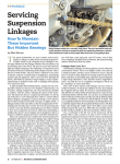
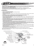
ATV
PODIUM x
Owner’s Manual
FOX FACTORY INC. 130
hangar way, Watsonville, CA 95076
TEL 1.800.FOX.SHOX FAX 831.768.7026 WEB WWW.FOXRACINGSHOX.COM
notice: the ATVs pictured in this manual may not resemble your actual ATV. in
any case, the procedures outlined in this manual will correctly enable you
to mount, setup, and tune the FOX PODIUM X on your particular ATV model.
denotes information that, if not followed, can cause damage to your
shock or lead to serious injury or death.
denotes information that may not be obvious, or that can help the
rider out with a difficult situation.
PAGE i
FOX FACTORY INC. 130 hangar way, Watsonville, CA 95076
USA
TABLE OF CONTENTS
Congratulations! 1
Consumer Safety
1
Understanding the PODIUM x
2
Reading the spring rate
Spring orientation
Changing springs (single spring)
Changing springs (dual spring)
4
4
5
6
Mounting the PODIUM X
8
Mounting a remote reservoir
Setting up the PODIUM x Adjusting spring preload (single and dual spring)
Adjusting spring crossover (dual spring only)
TUNING the PODIUM x General guidelines
Tuning recommendations
Spring force
Crossover point
REBOUND DAMPING
COMPRESSION DAMPING
How the DSC Works
What the Compression Adjustments Do
Maintaining the PODIUM x
Shock rebuild
8
9
11
12
15
15
15
16
16
17
19
20
21
22
22
QUICK REFERENCE guide
24
tuning notes
26
PN
605-00-061 REV F
1.800.FOX.SHOX
TEL
podium x owner’s manual
PAGE ii
FAX 831.768.7026
WEB WWW.FOXRACINGSHOX.COM
PODIUM x
features
•Lightweight aluminum body
• DLC coated shaft for reduced friction
• Position-Sensitive Damping on some models
• Piggyback body caps on some models
•Race-proven oil damping system
•External rebound damping adjuster
•External Dual Speed Compression (DSC) damping adjuster
• 100% rebuildable and revalveable
• 1-year factory limited warranty
•Spherical bearing ends
• 90-day valving guarantee
Dual Speed Compression
(DSC) ADJUSTER
PIGGYBACK
BODY CAP
shock body
preload ring
reservoir
crossover ring
tender coil spring
spring coupler
main coil spring
shaft
bottom-out bumper
spring retainer
rebound adjuster
lower eyelet/clevis mount
(EYELET shown)
Single spring version used
on certain applications
Remote reservoir required
for certain applications
PAGE iii
FOX FACTORY INC. 130 hangar way, Watsonville, CA 95076
USA
Congratulations!
Thank you for choosing the FOX PODIUM X for your ATV. In doing so, you have chosen one of
the finest suspension shocks in the world. FOX Racing Shox products are designed, tested and
manufactured by professionals in the industry in Santa Cruz County, California, USA.
As a consumer and supporter of FOX Racing Shox products, you need to be aware of the
importance of setting up your shock correctly to ensure maximum performance. This manual
provides step-by-step instructions of how to setup and maintain your shock. It is a good idea
to keep your receipts with this manual, and refer to it for service and warranty issues.
This manual does not contain step-by-step detailed service instructions for a reason: FOX
recommends that detailed service be performed by FOX Racing Shox or a qualified suspension professional.
For service and warranty information, refer to the Quick Reference Guide on page 24.
Consumer Safety
Riding an ATV can be dangerous and can result in death or serious
injury.
Take your responsibility to yourself and others seriously, and heed the following safety tips:
•Keep your ATV and suspension system in optimal working condition.
•Wear protective clothing, eye protection and always fasten your helmet before you ride.
•Know and ride within your limits.
PODIUM X shocks contain a high-pressure nitrogen charge. The charged portion of the shock should
only be opened by a FOX Racing Shox technician or a qualified suspension professional.
Opening a nitrogen pressurized shock can be dangerous and can
result in serious injury or death.
PN
605-00-061 REV F
1.800.FOX.SHOX
TEL
podium x owner’s manual
PAGE 1
FAX 831.768.7026
WEB WWW.FOXRACINGSHOX.COM
Understanding the PODIUM x
Your PODIUM X shock absorber sets the industry standard for performance and durability.
The PODIUM X has external compression and rebound damping adjusters, as well as spring
preload and crossover location adjustments (dual spring only). The PODIUM X contains a high
strength 2-inch bore aluminum body, and a 5/8" steel damper shaft that is super finished for
low-stiction and long seal life. The springs that come on your PODIUM X are customized for
your weight, riding style and terrain.
Dual Speed Compression (DSC) Adjuster
IFP
hose &
fittings
(hose not
shown)
Damping Piston
& Valving
bottom-out
Bumper
Oil
Chamber
PODIUM X Cross-Section
Your PODIUM X shock will either be fitted with dual springs or a single spring, depending
on your particular application. To maximize performance, different swingarm and linkage
combinations require different springs.
A single spring shock has a linear spring rate throughout the shock travel. Ride height (sag)
adjustments are made by adjusting the spring preload.
PAGE 2
FOX FACTORY INC. 130 hangar way, Watsonville, CA 95076
USA
A dual spring shock has a main spring (long) and a tender spring (short), which combine to
give a softer initial spring rate with a stiffer spring rate deep into travel. The vehicle ride-height
(sag) adjustments are made by varying spring preload, similar to the single spring shock (see
Adjusting Spring Preload on page 11). The shock bottoming resistance can be tuned by adjusting
the spring “crossover.” The spring crossover is the point in the shock travel where the spring
rate increases. The default setting is 55% of total shock travel. For information on changing
your spring crossover, refer to Adjusting Spring Crossover on page 12.
SPRING FORCE
Single Spring
Dual Spring
Spring Crossover Point
(Typically 55% of Total Travel)
SHOCK COMPRESSION
PN
605-00-061 REV F
1.800.FOX.SHOX
TEL
podium x owner’s manual
PAGE 3
FAX 831.768.7026
WEB WWW.FOXRACINGSHOX.COM
Reading the spring rate
The spring rate is printed directly on
the shock spring. The spring to the
left has an 8" free length, a 2.25" ID,
and a 300 lbs/in spring rate.
Spring orientation
When placing the spring(s) back on the shock body, it is important that the components are
assembled in the correct order, especially on the dual-spring model (see picture below).
2.25 I.D. THRUST CROSSOVER
WASHER
RING
PRELOAD
RING
TENDER COIL
SPRING
PAGE 4
FOX FACTORY INC. SPRING
COUPLER
2.5 I.D. THRUST
WASHER
COUPLER
GUIDE
MAIN COIL
SPRING
SPRING
RETAINER
130 hangar way, Watsonville, CA 95076
USA
Changing springs (single spring)
Step 1
Remove the shock from your ATV following the
procedures outlined in your service manual.
Step 2
Loosen the pinch bolt on the spring preload
ring and unthread the preload ring until the
spring freely moves up and down on the shock
body.
step 3
Lift up the spring and remove the spring
retainer. Your spring retainer will either have a
slot to fit over the shaft, or will be held in place
by a snap ring. If your spring retainer is held
in place by a snap ring, the snap ring must be
removed first to allow the spring retainer to
fit over the eyelet or clevis.
Preload
ring pinch
bolt
Snap
ring
Snap Ring Style Spring
Retainer
Spring
retainer
with slot
to fit over
shaft
Some models may require an automotive
spring compressor to help compress the
spring and remove the spring retainer. If
in doubt, please send your shock to an
authorized repair center or qualified
suspension professional.
Slot Style Spring Retainer
step 4
Slide the spring and thrust washers off the
shock body over the shaft end (eyelet/clevis end).
step 5
Orient the new spring correctly and slide it onto the shock body. Be sure to reinstall
the thrust washers at the same time.
step 6
Place the spring retainer back on the shock and under the spring. If your spring
retainer has a slot, ensure the slot is positioned over the flat portion of the spring
end (see Spring Orientation on page 4). If your spring retainer is held in place by
a snap ring, reinstall the ring into it's groove after the spring retainer has passed
over the eyelet or clevis.
PN
605-00-061 REV F
1.800.FOX.SHOX
TEL
podium x owner’s manual
PAGE 5
FAX 831.768.7026
WEB WWW.FOXRACINGSHOX.COM
step 7
Tighten the preload ring in order to take up any free play of the spring between
the retainer and preload ring. If your spring retainer is the snap ring version,
ensure the retainer is seated properly over the snap ring.
STEP 8
In order to adjust the preload and set the correct ride height or sag, refer to
Adjusting Spring Preload on page 11.
Changing springs (dual spring)
step 1
Remove the shock from your ATV
following the procedures outlined in your service manual.
step 2
Loosen the pinch bolt and spring
preload ring until the springs
freely move up and down on
the body.
step 3 Lift up the spring and remove pinch bolt
the spring retainer. Your spring
retainer will either have a slot to fit over the
shaft, or will be held in place by a snap ring. If
your spring retainer is held in place by a snap
ring, the snap ring must be removed first to
allow the spring retainer to fit over the eyelet
or clevis.
Preload ring
Snap
ring
Snap Ring Style Spring
Retainer
Spring
retainer
with slot
to fit over
shaft
Slot Style Spring Retainer
PAGE 6
FOX FACTORY INC. 130 hangar way, Watsonville, CA 95076
USA
Some models may require an automotive spring compressor to help
to compress the spring and remove the spring retainer. If in doubt,
please send your shock to an authorized repair center or qualified
suspension professional.
step 4 Slide the main spring, spring coupler, tender spring, and thrust washers off the
shock body over the shaft end (eyelet/clevis end), taking care to note the order
and orientation of the components.
step 5 Orient the new springs correctly (see Spring Orientation on page 4) and slide the
spring assembly onto the body. Take special care to ensure that the preload ring is
not on upside-down. The tender spring should fit snugly over the preload ring.
step 6
Place the spring retainer back on the shock and under the spring. If your spring
retainer has a slot, ensure the slot is positioned over the flat portion of the spring
end (see Spring Orientation on page 4) . If your spring retainer is held in place by
a snap ring, reinstall the ring into it's groove after the spring retainer has passed
over the eyelet or clevis.
step 7
Tighten the preload ring in order to take up any free play of the spring between
the retainer and preload ring. If your spring retainer is the snap ring version,
ensure the retainer is seated properly over the snap ring.
step 8
In order to adjust the preload and set the correct ride height or sag, refer to
Adjusting Spring Preload on page 11.
PN
605-00-061 REV F
1.800.FOX.SHOX
TEL
podium x owner’s manual
PAGE 7
FAX 831.768.7026
WEB WWW.FOXRACINGSHOX.COM
Mounting the PODIUM X
Shock fitment should only be conducted when the ATV is COLD. Do
not attempt to fit the shock to AN ATV that has been running or has
a hot engine or exhaust. If you must change the shock on a hot ATV,
be sure to use gloves and protective equipment.
step 1
Place the ATV on a workstand.
step 2
Following the procedures outlined in your service manual, remove the stock
shock from the ATV. Keep the stock nuts, bolts, washers, etc., as you will need
these to mount the PODIUM X.
step 3
Install the PODIUM X into the upper and lower mounts following the assembly
procedures and torques outlined in your ATV service manual.
step 4
Reference the enclosed setup sheet for information relating to the shock orientation and reservoir mounting specific to your ATV.
If your specific application utilizes a lower clevis mount, a small
drop of blue loctite® on the thread is recommended during
installation.
step 5
Set rider sag on the PODIUM X as detailed in the following sections.
Mounting a remote reservoir
Pay careful attention to the routing notes/pictures in the supplemental setup sheet. Care
should be taken to make sure the hose does not contact hot exhaust components or any
moving suspension parts.
If necessary, use cable ties to hold the hose in place. Excessive heat and/or vibration will
damage the hose and its plastic covering.
Avoid sharp bends in the hose—this may cause damage and result in hose failure.
Do not allow the hose fittings to touch any part of the frame. This will cause damage to the
fitting and frame due to engine vibration.
PAGE 8
FOX FACTORY INC. 130 hangar way, Watsonville, CA 95076
USA
Setting up the PODIUM x
To get the best performance out of your PODIUM X, it is necessary to adjust the vehicle rideheight or “sag.” Sag is how much the shock compresses, or “sags,” when you sit on your ATV.
As a general rule, your vehicle’s sag should be 35% – 45% of full wheel travel. There are many
factors that will influence your sag setting and ride height preference, including tire diameter,
terrain and riding style. Use the following procedure to accurately measure and set the correct
ride-height (sag) for your ATV:
Set the front and rear ride height (sag) simultaneously.
step 1
Position the bike on a flat surface
and clear of any obstacles.
step 2
Place pieces of cardboard under
each wheel. As the suspension
is compressed, the front wheels
move outward. This is called
“scrub”. Placing the cardboard
under the wheels allows the suspension to move more freely.
step 3
While wearing your riding gear,
mount the ATV and sit in your normal riding position, with both hands on the bars.
step 4
Aggressively bounce up and down on the quad several times and allow the quad
to settle.
Due to the nature of high-pressure seals IN THE FRONT AIR SHOCKS, the
shocks may require an initial compression stroke to fully lubricate
internal sliding surfaces to allow for smooth operation. This is
most apparent after the ATV has been sitting for a while.
PN
605-00-061 REV F
1.800.FOX.SHOX
TEL
podium x owner’s manual
PAGE 9
FAX 831.768.7026
WEB WWW.FOXRACINGSHOX.COM
step 5
Gently assume a seated position.
step 6 Have a friend push down on the front
end of the vehicle. While the suspension is compressed, turn the bars back
and forth. Turn the bars back straight
and have the friend release the front
suspension.
step 7
While still seated on the ATV, have a
friend measure the vertical distance
from the ground plane to the chassis, under the foot pegs (rear frame
height) and the distance from the
ground plane to the chassis at the front
engine mount (front frame height). If
your vehicle has a skid plate, measure
to the bottom of that.
Measuring the front frame height just
under the front motor mount.
PAGE 10
FOX FACTORY INC. Measuring the rear frame height just in
front of the foot peg.
130 hangar way, Watsonville, CA 95076
USA
step 8
The frame heights should follow the recommended guidelines outlined in the
table below.
Terrain /
riding discipline
FRONT TIRE
DIAMETER
REAR TIRE
diameter
Rear frame Front frame
height
height
MOTOCROSS
20"
18"
7"
7 1/4"
CROSS COUNTRY
21"
20"
7 1/2"
7 3/4"
WORCS
21"
20"
7 3/4"
8"
DESERT
23"
22"
9"
9 1/4"
SUPERMOTO
19"
18"
5 1/2"
5 3/4"
If your ATV is sitting too low in the rear, increase the PODIUM X spring preload (See Adjusting
Spring Preload below), and repeat all the steps above until the desired sag is reached.
Adjusting spring preload (single and dual spring)
step 1
Using a 4mm hex key, loosen the pinch-bolt on the preload ring.
step 2
a)Turn the preload ring clockwise (when viewed from above) to increase
the preload.
b)Turn the preload ring counter-clockwise (when viewed from above) to
decrease the preload.
step 3
Once you have reached the desired setting, torque the pinch-bolt to lock the ring.
If you are Adjusting Spring Preload with the shock not mounted on
the ATV, be sure to turn the preload ring a whole number of complete
turns, maintaining the same angular orientation. This will ensure
that you will still be able to access the pinch-bolt when the shock
is installed on the ATV.
If you adjust your spring preload you will also need to adjust your
crossover ring location (Dual spring ONLY) to maintain the same
crossover point. See the section setting the crossover point on page
13 for details.
DO NOT ADD MORE THAN 1/2" OF PRELOAD TO THE SPRING. Excessive spring
preload may result in coil-bind, which could potentially be damaging
to the shock and springs. If you require more than 1/2" PRELOAD to
reach the desired sag point, you will need to exchange the spring(s)
for a higher RATE BY CONTACTING FOX RACING SHOX OR YOUR LOCAL FOX
RACING SHOX DEALER.
PN
605-00-061 REV F
1.800.FOX.SHOX
TEL
podium x owner’s manual
PAGE 11
FAX 831.768.7026
WEB WWW.FOXRACINGSHOX.COM
Adjusting spring crossover (dual spring only)
The spring crossover point is an important tuning parameter. A softer initial spring rate offers
improved traction and hook-up while a higher spring rate deep into travel helps to resist
bottoming on jump landings. As a rough guideline, the spring crossover point should be as
deep into travel as possible without experiencing excessive bottoming. The crossover point is
defined as a percentage of the total shock travel. The factory setting for the spring crossover
point is 55%. This means that a 5" travel shock would have the crossover point at 2.75" (5.0"
x 0.55) into the shock travel.
In order to calculate your spring crossover ring placement, you need to know four important
pieces of information:
1. Metal to metal shock travel in inches (measure before spring installation).
2. Main Spring Rate (lb/in) — marked on spring (see Reading the Spring Rate on page 4).
3. Tender Spring Rate (lb/in) — marked on spring (see Reading the Spring Rate on page 4).
4.Desired crossover point (as a percentage).
The shock travel is the exposed length of the shaft (including the bumpstop) when the shock
is fully extended. It may be easiest to measure before you install the shock.
shock travel
Some shocks use external spacers below the bump-stop to limit
travel. Do not include the spacer length as part of the travel.
The crossover point is a tunable parameter. It should be between
45% to 65%.
PAGE 12
FOX FACTORY INC. 130 hangar way, Watsonville, CA 95076
USA
SETTING the crossover point
step 1
Set the spring preload as described in Adjusting Spring Preload on page 11.
step 2
Once you have established the correct preload, mount the ATV on a stand to keep
the rear wheels off the ground. The shock should be fully extended.
Step 3
Using a 2.5mm hex key, loosen the set screw retaining the crossover ring.
step 4
Determine the Spring Correction Factor using the following table:
Tender Spring Rate (lb/in)
SPRING
CORRECTION
FACTOR
Main Spring Rate (lb/in)
200
225
250
275
300
325
350
375
400
425
450
475
500
0.487 0.500
500
0.286
0.310
0.333
0.355
0.375
0.394
0.412
0.429 0.444 0.459
0.474
600
0.250
0.273
0.294
0.314
0.333
0.351
0.368
0.385 0.400
0.415
0.429 0.442
700
0.222
0.243
0.263
0.282 0.300
0.317
0.333
0.349 0.364
0.378
0.391
0.404
0.417
800
0.200 0.220 0.238
0.256
0.289 0.304
0.319
0.347 0.360
0.373
0.385
900
0.182
0.200
0.217
0.234 0.250 0.265 0.280 0.294 0.308
0.321
0.333
0.345
0.357
1000
0.167
0.184
0.200
0.216
0.286 0.298
0.310
0.322
0.333
0.273
0.231
0.245
0.259
0.273
0.333
0.455
step 5Use the following formula to calculate crossover ring placement:
Crossover Ring Placement = Shaft Travel (in.) x Crossover Point x Spring Correction Factor
EXAMPLE
•A 5.2" travel shock with a 375 lb/in main spring and a 800 lb/in tender spring.
•The crossover point is set at 55%.
•From the table above, the spring correction factor is 0.319.
•From the above formula, the crossover ring placement value
is = 5.2 x 0.55 x 0.319 = 0.912 inches
In the above example, 55% is written as 0.55.
PN
605-00-061 REV F
1.800.FOX.SHOX
TEL
podium x owner’s manual
PAGE 13
FAX 831.768.7026
WEB WWW.FOXRACINGSHOX.COM
step 6
Adjust the crossover ring (as shown below) so that its distance from the spring
coupler is equal to the crossover ring placement value calculated in Step 5. Torque
the crossover ring set-screw once complete.
Crossover ring
placement value
should match the
distance from the
top of the spring
coupler to the
bottom of the
crossover ring.
step 7
Remove the ATV from the stand.
You may need a small, flexible ruler or measuring device to
accurately determine the crossover ring location. Another useful
way of measuring is to count the threads on the body (the thread
pitch on the body is 14 threads per inch). If you know the crossover
ring location, multiply by 14 to get the number of threads between
the spring coupler and crossover ring. In the example above, 0.912
inches = 0.912 x 14 = 12.8 threads.
Applying excessive torque to the crossover ring set screw will
result in deformation of the shock body and crossover ring. This
set screw only needs very light (two-finger) torque.
Changing the spring preload, tender or main spring free-length or
rate will mean that you need to reset the crossover ring
placement.
PAGE 14
FOX FACTORY INC. 130 hangar way, Watsonville, CA 95076
USA
TUNING the PODIUM x
General guidelines
Go out and ride. Tune your senses to what the ATV’s rear end is doing. Sometimes you know the
ATV isn’t handling quite right, but it may be hard to tell whether the problem is too little rebound
damping or too much compression damping. Sometimes the difference in “feel” is subtle.
Some of the distinctions are minute. If the damping doesn’t seem quite right, make your best
guess as to what change will help, then try it. If handling doesn’t improve, make another change
in the opposite direction. Keep experimenting like this until the ride feels best.
It is common practice for riders to “test” shock absorber damping by pushing down on the
back of the ATV and observing the shock response. This test is useful, but very limited. You
should be aware that this test only involves low-speed damping action. It will tell you nothing
about shock response at medium and high shaft speeds.
Tuning recommendations
The percentage change in damping when going from one click to the next click is fairly
small. This is so you can really fine tune your shock. A one click change is hard to notice.
Therefore, FOX recommends making changes of two clicks at a time. For example, if after
testing you feel compression is too soft, try a two-click change (clockwise on compression
adjuster). If that feels just right, then you’ve got it. On the other hand, if that now feels a
little too stiff, then you’ve got it “bracketed”. Go back one click (counter-clockwise) and it
should now feel just right.
These recommendations apply to both rebound and compression damping.
If you want to know your current setting, both adjusters should
be baselined by turning them clockwise and counting the number of
clicks until the adjuster lightly bottoms. Do not overtighten.
Compression and rebound adjustment settings are counted as clicks
out from full in or full clockwise position.
PN
605-00-061 REV F
1.800.FOX.SHOX
TEL
podium x owner’s manual
PAGE 15
FAX 831.768.7026
WEB WWW.FOXRACINGSHOX.COM
Spring force
At this point you have set the sag of your vehicle by adjusting the preload ring. If you feel
that the rear of the vehicle is too low as you are riding, increase preload. If the vehicle is too
high, decrease preload.
Never increase preload more than 1/2". If you need more spring force,
you will need to go to the next higher spring rate.
IF YOU NEED TO DECREASE THE SPRING PRELOAD TO THE POINT WHERE THE
SPRING IS LOOSE WHEN THE VEHICLE IS ON A STAND AND THE SHOCK IS FULLY
EXTENDED, IT IS NECESSARY TO OBTAIN A LOWER RATE SPRING.
Crossover point
The crossover point should be between 45% and 65% of travel. The default setting is 55%.
If you want increased bottoming resistance, decrease the crossover point towards 45% (the
crossover ring will move closer to the spring coupler).
If you are not bottoming and want decreased bottoming resistance, increase the crossover
point towards 65% (the crossover ring will move away from the spring coupler).
Setting a crossover point outside of the recommended range (45%
– 65%) may result in spring coil-bind and damage to the shock and/or
springs.
If you feel that you are crashing through your available travel too
quickly on big bumps, try decreasing the crossover point. Conversely,
if you feel that you are not fully utilizing your available travel,
try increasing the crossover point.
Applying excessive torque to the crossover ring set screw will
result in deformation of the shock body and crossover ring. This
set screw only needs very light (two-finger) torque.
PAGE 16
FOX FACTORY INC. 130 hangar way, Watsonville, CA 95076
USA
REBOUND DAMPING
Rebound damping controls the rate at which the shock returns after it has been compressed.
The proper rebound setting is a personal preference, and changes with rider weight, riding
style and conditions. A rule of thumb is that rebound should be as fast as possible without
kicking back and pushing the rider off the saddle.
The rebound screw (see picture below) is located on the shaft end of the shock, and is adjusted
using a screwdriver.
For slower rebound — turn the rebound adjuster knob clockwise.
For faster rebound — turn the rebound adjuster knob counter-clockwise.
Rebound damping Troubleshooting
Symptom
Remedy
• Bucking
• Tops out too hard
Set slower rebound
• Packing in repetitive bumps
• Chatter
Set faster rebound
Symptoms of Too Much Rebound Damping
•Rear end tends to wash out or slide out on hard-packed
sweeper turns with small bumps, especially on off-camber
“washboard” turns.
•Rear end skips too much when braking on “washboard”
sections and does not develop good braking power.
•Poor rear wheel traction when accelerating over small
repetitive bump sections.
•Rear end gets harsh and hard to control when hitting a series
of medium or large rolling bumps at high speed. The first
few bumps in the series don’t seem bad, but after that, the
rear end gets harsh and starts jumping around.
Rebound Adjuster
Screw
Too much damping prevents the wheel from extending quickly enough
before hitting the next bump. After the fifth or sixth bump, you may
have minimal travel LEFT. THIS SITUATION IS CALLED “PACKING”.
PN
605-00-061 REV F
1.800.FOX.SHOX
TEL
podium x owner’s manual
PAGE 17
FAX 831.768.7026
WEB WWW.FOXRACINGSHOX.COM
Symptoms of Too Little Rebound Damping
•The tendency to wash out or slide out on washboard sections is also possible with too little
rebound damping. The critical difference in this case is that the back of the ATV is bouncing
up and down too much because there isn't enough control on the extension stroke.
•Too much kicking up when braking on downhill sections with small bumps or washboard
surfaces.
•Rear end kicks up when hitting large rolling bumps at high speeds. Kicking is especially
noticeable on steep downhills with deep rolling bumps or after landing a large jump.
The shock will extend too quickly if there is not enough damping to
control the spring extension force.
Tuning suggestion
Once you are comfortable riding the ATV and would like to fine tune the rebound damping
setting, find a table-top jump that you can hit consistently and safely, landing as flat as possible.
As a general rule you want as little rebound damping as possible so that the suspension returns
quickly, but still enough rebound damping that the rear of the ATV does not oscillate upon
landing. After the jump landing, the rear of your ATV should return quickly to ride-height and
then remain still. If the rear suspension continues to oscillate several times after landing, try
increasing rebound damping (slower). If the suspension does not oscillate after landing, try
decreasing rebound damping (faster). This procedure should allow you to close in, or bracket,
on the desired rebound damping setting.
PAGE 18
FOX FACTORY INC. 130 hangar way, Watsonville, CA 95076
USA
COMPRESSION DAMPING
Compression damping controls the rate at which the shock compresses when it encounters a
bump. The proper compression setting is a personal preference and changes with rider weight,
riding style and conditions.
The Dual Speed Compression (DSC) knob (shown on page 20) is located on the oil reservoir.
For more compression — turn the compression adjusters clockwise.
For less compression — turn the compression adjusters counter-clockwise.
Compression damping Troubleshooting
Symptom
Remedy
• Rigid, harsh ride
Set less compression
• Bottoms-out easily
Set more compression
Symptoms of Too Much Compression Damping
•The rear end is harsh over small bumps. Shock seems to stay almost rigid instead of absorbing
bumps.
•The rear end is harsh at high speeds over large or medium square-edged bumps. The shock
stays too rigid and does not use enough travel to absorb bumps.
•The shock rarely or never seems to bottom-out, even off the biggest jumps.
Symptoms of Too Little Compression Damping
•The shock bottoms-out on medium-sized bumps and the bottom of deep, smooth gullies,
or rising portions of deep, rolling sand whoops.
•At high speed the rear end takes medium square-edged bumps smoothly, but bottoms out
too easily on larger bumps.
•Bottoms out too easily on large jump landings.
PN
605-00-061 REV F
1.800.FOX.SHOX
TEL
podium x owner’s manual
PAGE 19
FAX 831.768.7026
WEB WWW.FOXRACINGSHOX.COM
LSC Adjuster (Low-Speed Compression)
Turn LSC clockwise with a flat screwdriver to
increase low-speed compression damping. LSC
setting is denoted as ‘clicks’ out from fully closed
(full clockwise).
DSC Knob
HSC Adjuster (High-Speed Compression)
Turn clockwise with a wrench or socket to increase
or add high-speed compression damping. HSC
setting is denoted as ‘clicks’ out from full firm (full
clockwise). Tech note: When the HSC adjuster
is turned clockwise, it will actually back out of
the housing. This is due to a left-hand-thread
arrangement.
How the DSC Works
The DSC valve has two parallel paths through which oil flows. The low-speed circuit is an
adjustable needle and jet seat. The high-speed circuit is a valve stack backed by a compression
spring. The preload in this spring controls the point at which the valve stack opens. These two
independent adjusters are shown in the diagram above.
PAGE 20
FOX FACTORY INC. 130 hangar way, Watsonville, CA 95076
USA
What the Compression Adjustments Do
The LSC (low speed compression) adjuster primarily affects the compression damping during
slow suspension movements such as g-outs or smooth jump landings. It also affects wheel
traction and the harshness or plushness of the vehicle (note that low-speed has nothing to
do with the speed of the vehicle!). Choose a LSC setting that gives good body control (roll in
corners, dive under braking, squat under acceleration, etc.) without causing excessive harshness or loss of traction. The graph below (left) shows the typical range of adjustability for
the LSC adjuster from full firm to full soft with the HSC adjuster held constant at 10 clicks out.
The HSC (high speed compression) adjuster mainly affects the compression damping during
medium to fast suspension movements such as steep jump faces, harsh flat landings and
aggressive whoops. The goal is to run as little high-speed compression damping as possible
without bottoming. The graph below (right) shows the typical range of adjustability for the
HSC adjuster from full firm to full soft with the LSC adjuster held constant at 10 clicks.
0
0
20 4
VelociTy (in/s)
0
60 8
0
100
120
140
-100
-200
-300
-300
-400
605-00-061 REV F
1.800.FOX.SHOX
0
20 4
0
60 8
0
100
120
140
-100
-400
-500
TEL
0
-200
-500
Characteristic graph showing the effect of
changing the LSC Adjuster.
PN
force (lbf)
force (lbf)
VelociTy (in/s)
-600
Characteristic graph showing the effect of
changing the HSC adjuster.
podium x owner’s manual
PAGE 21
FAX 831.768.7026
WEB WWW.FOXRACINGSHOX.COM
Maintaining the PODIUM x
Proper inspection and maintenance procedures are crucial to maintaining the high performance
and durability of your PODIUM X shock. Proper inspection and maintenance prevents headaches
and equipment failure, not to mention lackluster performance at the races and your absence
from the podium.
You should clean your PODIUM X before and after every ride for optimal performance. Use a
mild detergent and rag to clean off any and all debris from your shock. Be sure to clean the
area located under the bottom-out bumper. Avoid using a pressure washer directly on the
shock as this can drive dirt past the seals.
Along with properly cleaning your shock, you should also inspect the following areas before
every ride. Consult the shock image at right for the location of each inspection location:
1.
Check the reservoir and hose (if applicable) for any signs of damage.
2. Check the shaft for any signs of leakage or damage.
3. Check the spring and shock body for any signs of damage.
4. Check the shock’s mounting points and make sure all bolts are properly fastened.
Shock rebuild
Just as the oil in your engine breaks down with time and must be replaced, the oil in your
PODIUM X shock must be serviced periodically. The service interval depends on how frequently
and severely the ATV is ridden. As a guideline, if you race hard every weekend you may want to
change the oil in your shock at least once mid-season. Otherwise, it is generally recommended
to service the shock in the off-season. Only FOX Racing Shox or an Authorized Factory Service
Center should perform this procedure.
PAGE 22
FOX FACTORY INC. 130 hangar way, Watsonville, CA 95076
USA
4
3
1
2
1
4
PN
605-00-061 REV F
1.800.FOX.SHOX
TEL
podium x owner’s manual
PAGE 23
FAX 831.768.7026
WEB WWW.FOXRACINGSHOX.COM
QUICK REFERENCE guide
terms used
Suspension
• Compression: downward travel of the suspension. Actions that move the endpoints of the
shock closer together.
• Compression damping: oil damping resistance felt when trying to compress the shock.
• Frame clearance: distance between the frame and other moving parts, like the shock.
• Negative travel: distance the suspension or shock extends from the static ride height. Also
referred to as ‘free sag’.
• Preload: initial force on the spring. Preload is used to adjust rider sag.
• Ride height: with the rider on the ATV, the distance from the ground to some point on the
frame.
• Rebound: force required to extend the shock or suspension. Can also refer to the extending
action of the suspension.
• Rebound damping: oil damping resistance that controls the rate at which the shock extends
after being compressed.
• Rider sag: amount the shock compresses with the rider sitting on the ATV in a normal riding
position.
• Free sag: amount that the ATV “sits” into travel. Usually measured from the ground to a point
on the frame, or as shock stroke, and without a rider on the ATV.
• Spring rate: force required to compress a spring one inch. Measured in lb/in. or Kg/mm.
• Stroke: amount of shock travel.
• Travel: total amount the shock compresses.
• Valving: refers to the combination of shims or damping valves on the piston face used to
achieve a specific ride characteristic.
• Wheel travel: distance the wheel moves when the suspension is cycled through its full travel.
riding
• Bottoming: vehicle has bottomed-out when the suspension reaches the limit of its travel and
stops further downward motion.
• Bucking: kicking motion on a rider after a bump or jump landing.
• Chatter: small bumps similar to braking bumps prior to a corner or berm. Often refers to the
harshness felt when riding over small, closely spaced bumps.
• Fading: slow loss of shock damping usually due to heat.
• Packing: when the shock does not return quickly enough to adequately absorb the next
bump in a repetitive bump sequence.
• Spiking: sharp impact cause by a square-edge bump.
• Squat: when the rear of the vehicle “sits” down either due to weight transfer or driveline
forces.
• Stiction: initial force that needs to be overcome to start the suspension stroke.
• Topping-out: when the suspension is fully extended.
service
intervals
• Before every ride: Clean and inspect your shock.
• Every ride season: Shock rebuild by a FOX Certified Technician or FOX Racing Shox.
PAGE 24
FOX FACTORY INC. 130 hangar way, Watsonville, CA 95076
USA
contact
info
FOX Racing Shox
130 Hangar Way, Watsonville, CA 95076, USA
Phone: 1.831.274.6500 Fax: 1.831.768.7026
North America: 1.800.FOX.SHOX (1.800.369.7469)
E-mail: [email protected]
Website: www.FOXracingshox.com
Business hours: Monday – Friday 8 a.m.–5 p.m. PST
method of
payment &
shipping
Visa
MasterCard
Cashier's Check
FOX Racing Shox uses
UPS Ground Service
within the USA
disclaimer
FOX Racing Shox is not responsible for any damages to you or others arising from riding,
transporting, or other use of your PODIUM X shock. In the event that your shock breaks or
malfunctions, FOX Racing Shox shall have no liability beyond the repair or replacement of your
shock pursuant to the terms outlined in the warranty provisions of this manual.
warranty
policy
The factory warranty period for your shock is one year (two years for countries in the EU) from
the original date of purchase. A copy of the original purchase receipt must accompany any
shock being considered for warranty service. Warranty is at the full discretion of FOX Racing
Shox and will cover only defective materials and workmanship. Warranty duration and laws may
vary from state to state and/or country to country. Parts, components and assemblies subject
to normal wear and tear are not covered under this warranty. FOX Racing Shox reserves the
right to all final warranty or non-warranty decisions.
valving
guarantee
If it is determined that a PODIUM X requires a valving change within the first 90 days of ownership, FOX will perform the re-valve at no charge for the original consumer. The consumer is
required to follow the Service Policy procedure below and is responsible for all shipping costs
to and from FOX Racing Shox. Unless otherwise specified, FOX Racing Shox will return ship the
shock(s) via UPS Ground Service.
service
policy
• FOX Racing Shox offers 5-business day turnaround, which may vary.
• Obtain an RA (Return Authorization) number and shipping address from FOX Racing Shox at
800.FOX.SHOX. Outside the USA, contact the appropriate International Service Center.
• Mark the RA number and return address clearly on the outside of the package and send to
FOX Racing Shox (see contact info above) or your International service center with shipping
charges pre-paid by the sender.
• Proof-of-purchase is required for warranty consideration.
• Include a description of the problem, ATV information (manufacturer, year and model), type
of FOX product and return address with daytime phone number.
specific
exclusions
from
warranty
• Parts replaced due to normal wear and tear and/or routine maintenance
• Parts subject to normal wear and tear and/or routine maintenance
• Bushings
•Seals (after the 90-day seal warranty period expires)
•Suspension fluids
• Crash damage
general
exclusions
from
warranty
• Installation of parts or accessories not qualitatively equivalent to genuine FOX Racing Shox
parts.
•Abnormal strain, neglect, abuse and/or misuse
•Accident and/or collision damage
• Modification of original parts
•Lack of proper maintenance
•Shipping damages or loss (purchase of full value shipping insurance is recommended)
• Damage to interior or exterior caused by rocks, crashes or improper installation
• Oil changes or service not performed by FOX Racing Shox or an Authorized Service Center
PN
605-00-061 REV F
1.800.FOX.SHOX
TEL
podium x owner’s manual
PAGE 25
FAX 831.768.7026
WEB WWW.FOXRACINGSHOX.COM
tuning notes
PAGE 26
FOX FACTORY INC. 130 hangar way, Watsonville, CA 95076
USA
PN
605-00-061 REV F
1.800.FOX.SHOX
TEL
podium x owner’s manual
PAGE 27
FAX 831.768.7026
WEB WWW.FOXRACINGSHOX.COM
© 2009 FOX FACTORY, INc. FOX Racing Shox is a trademark of FOX Factory, Inc.
i the FOX logo is a registered trademark of FOX Factory, Inc. PN 605-00-061 REV F