1
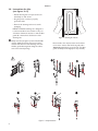
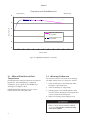
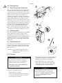
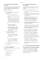
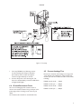
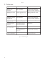
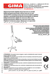
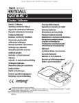
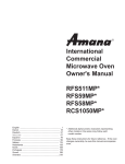
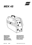
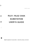
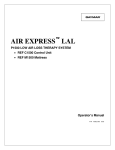
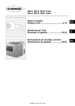
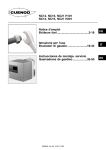
Medi-Temp III REF FW600 Series Blood/Fluid Warmer [ENGLISH] Réchauffeur de sang/liquide Medi-Temp III série REF FW600 [FRANÇAIS] Riscaldatore per sangue/fluidi Medi-Temp III serie REF FW600 [ITALIANO] Recalentador de sangre y fluidos Serie REF FW600 Medi-Temp III [ESPAÑOL] Aquecedor de Sangue/Líquidos Medi-temp III Série REF FW600 [PORTUGUÊS] Medi-Temp III REF FW600-Serie Blut-/Flüssigkeitswärmer [DEUTSCH] Medi-Temp III REF FW600 Series bloed-/vloeistofverwarmer [NEDERLANDS] Medi-Temp III serie REF FW600 varmeaggregat til blod/væske [DANSK] Medi-Temp III värmeaggregat för blod/vätska serie REF FW600 [SVENSKA] Medi-Temp III REF FW600 -sarjan veren/nesteenlämmitin [SUOMI] Medi-Temp III REF FW600-serie blod-/væskeoppvarmer [NORSK] Óýóôçìá ÈÝñìáíóçò Áßìáôïò/Õãñþí Medi-Temp III ôçò ÓåéñÜò REF FW600 [ÅËËÇÍÉÊÁ] Operators Manual/Service Manual Manuel d’utilisation/Manuel d’entretien Manuale per l’operatore/Manuale di manutenzione Manual del operador/Manual de servicio Manual do Utilizador/Manual de Serviço Bedienungs-/Wartungshandbuch Bedieningshandboek/Onderhoudshandboek Operatørhåndbog/Servicemanual Instruktionsbok/Servicehandbok Käyttäjän käsikirja/huoltokäsikirja Brukerhåndbok/servicehåndbok Åã÷åéñßäéï ×ñÞóçò/Åã÷åéñßäéï ÓõíôÞñçóçò P/N 11294-000 11/01 ENGLISH Table of Contents Sec 1.0 2.0 3.0 4.0 5.0 6.0 7.0 8.0 Topic Page Indications for Use ........................................ 1 Product Description ..................................... 2 Instructions for Use ...................................... 4 Safety Systems ................................................ 7 Cleaning ........................................................... 7 Functional Check/Safety Inspection .......... 8 Troubleshooting .......................................... 10 Technical Specifications .............................. 11 Before you begin . . . Important Before using the Medi-Temp III FW600 Series Blood/ Fluid Warmer, please read and understand this Operator’s Manual and the SAFETY PRECAUTIONS prior to use. If you have any questions, please contact your local dealer for assistance. Warranty The Medi-Temp III FW600 Series Blood/Fluid Warmer is warranted free of defects in material and workmanship for a period of one (1) year. The Disposable Warming Sets are warranted free of defects in material and workmanship for a single application. A copy of the warranty is available upon request. Gaymar disclaims all implied warranties including, but not limited to, the implied warranties of merchantability and of fitness for a particular purpose. ENGLISH 1.0 Indications for Use This device is intended to aid in the prevention of inadvertent hypothermia during administration of blood, blood products, and other fluids. 1.1 Safety Precautions DANGER Risk of electric shock. No user serviceable parts inside. WARNING • All air must be removed from the fluid lines prior to connection to the patient. • Monitor the fluid lines to insure they are air free. Never administer fluids if there are air bubbles in the line between the bubble trap and the patient connector. • Monitor the fluid level in the bubble trap frequently. Bubbles released during heating are captured in the trap. To refill the trap, insert a sterile syringe into the valve and draw air out until the trap is (2/3) full. Do not allow the bubble trap to go below one-quarter (1/4) full. • The bubble trap must be kept mounted and in the vertical position at all times. Failure to follow the above warnings could result in the introduction of air to the patient. Introduction of air to the patient could result in death or serious injury. CAUTION • US Federal law restricts this device to sale by or on the order of a physician. • Do not immerse in cleaning and/or sterilization solution. Do not submerge or soak unit; it is fluid resistant, not fluid proof. • For grounding reliability of the Blood/Fluid warmer, plug only into a properly grounded outlet. • The RUN/STANDBY switch does not provide isolation from the mains. Isolation from the mains (IEC 601-1) can only be achieved by disconnecting the cord from the mains. 1 ENGLISH REMOVE FROM USE indicator STANDBY indicator IV pole clamp SETPOINT switch button RUN /STANDBY switch Bubble trap receiver Cassette slot Figure 1—FW600 series Blood/Fluid Warmer 2.0 Product Description The Medi-Temp III FW600 Series Blood/Fluid Warmer is a dry-heat device designed for safe and rapid warming of blood, blood products and other fluids through the utilization of disposable blood/fluid warming sets. The warmer does not provide fluid flow rate control. Blood, blood products and other fluids normally refrigerated, can be rapidly warmed to user selectable temperatures of between 38.0°C–43.0°C at flow rates up to 300 ml/min. Room temperature fluids can be warmed at flow rates up to 500 ml/min. The disposable Blood/Fluid warming sets are available in Standard, Standard with Extensions, Pediatric, and High Flow models. 2.1 Warmer The warming unit is designed to be IV pole mounted. The device has no on/off switch. Connection to the AC supply is indicated by a green STANDBY mode indicator, located on the front panel. In STANDBY mode, no power can be applied to the heater. To begin normal operation, the RUN/STANDBY button must be pressed. 2 When this occurs, an LED temperature display located on the front panel will display the actual fluid temperature or the setpoint temperature in °C. The setpoint is user selectable from 38.0°C–43.0°C in 1.0°C increments, by use of the SETPOINT switch on the front panel. Also located on the front of the unit is a slot for insertion of the disposable warming set. On the right side of the unit, just below the IV pole clamp, is a receiver for the disposable warming set’s bubble trap. 2.2 Disposable sets The Medi-Temp III FW600 Series Blood/Fluid warming unit is designed to be used only with Gaymar D25000 series disposable warming sets. The following warming sets (figure 2) are designed for use up to 300 mm Hg pressure. Contact your local dealer for more information. ENGLISH Description Catalog Number Application Priming Volume Standard D25340CE KVO—150 ml/min 39 ml Standard with 48" extension D25310CE KVO—150 ml/min 48 ml Standard with 60" extension D25315CE KVO—150 ml/min 50 ml Pediatric with 30" extension D25320CE KVO—100 ml/min 30 ml High Flow with 48" extension D25330CE 100—500 ml/min 79 ml KVO = minimum flow required to keep veins open Figure 2—D25000 series warming sets G A D B C F D A Flexible Cassette B Manual Air Eliminator (Relief Valve) C Bubble Trap D Clamp E Male Luer (to Patient) F Female Luer (to Blood/Fluid Source) G Blue Guide Rail E Figure 3—Warming set and bubble trap 3 ENGLISH 3.0 Instructions for Use (see figures 3—5) • Attach warming unit to IV pole and secure with clamp on side of unit. • Plug the power cord into a properly grounded outlet. • Remove the warming set from it’s sterile packaging NOTE: The flexible warming set is designed so it can be inserted into the warmer in only one orientation. Orient the cassette so that the blue guide rail is inserted into the bottom of the warming unit. Figure 4—Inserting the cassette Grasp each rail (see figure 4). Stretch the flexible cassette slightly and insert the front end of the cassette into the front of the warming unit, with the blue guide rail facing down. Align the rails to each of the slotted openings. Move hands to the rail protrusions and continue to insert the cassette until the clear guide rail is almost flush with the front of the unit. (The blue guide rail will protrude slightly for easy removal.) Figure 5—Setup instructions 4 ENGLISH NOTE: holding down the SETPOINT switch indefinitely will not increment the setpoint. CAUTION When fully inserted, the clear guide rail should protrude no more than 0.5 cm from the front of the warming unit. Failure to fully insert the cassette may result in damage to the cassette. Close warming set input clamp. Remove the protector from the female luer of the warming set and connect it to the male luer on the IV administration set. Remove the protector from the male luer of the warming set. To minimize temperature drop and priming volume, remove unnecessary lead extensions at this time. Invert the bubble trap. Open warming set input clamp. Allow fluid to prime the set. When the bubble trap fills to approximately (2/3) full, close the output clamp. Re-invert the bubble trap and place it into the bubble trap receiver on the side of the warming unit. WARNING The bubble trap must be mounted and kept in a vertical position at all times. Failure to do so could result in the introduction of air to the patient, resulting in death or serious injury. Press the RUN/STANDBY switch After the selection has been made, the display will continue to flash this setpoint for approximately 3 seconds, then revert to displaying the actual fluid temperature. The setpoint can be checked at any time during the procedure by momentarily pressing the SETPOINT switch. If required, connect an extension for patient connection. Purge air from remaining length of tubing by opening output clamp and allowing fluid to flow. WARNING • All air must be removed from the fluid lines prior to connecting to the patient. • Monitor the fluid lines to ensure they are air free. Never administer fluids if there are air bubbles in the line between the bubble trap and the patient connector. Failure to do so could result in the introduction of air to the patient, resulting in death or serious injury. WARNING on the front of the unit. Upon successful completion of self-diagnostics, the display will flash the setpoint for approximately 3 seconds, then begin warming the fluid to the selected temperature. The setpoint most recently used is retained in memory, even after power is removed. To select an alternate setpoint, first press the SETPOINT switch momentarily. This will cause the setpoint to be displayed and flash for approximately 3 seconds. While the display is flashing the setpoint, the user may select any setpoint between 38.0°C and 43.0°C in 1.0°C increments by repeatedly pressing the SETPOINT switch. Monitor the fluid level in the bubble trap frequently. Bubbles released during heating are captured in the trap. To refill the trap, insert a sterile syringe into the valve and draw air out until the trap is two-thirds (2/3) full. Do not allow the bubble trap to go below one-quarter (1/4) full. Failure to monitor the fluid level in the bubble trap could result in the introduction of air to the patient, resulting in death or serious injury. 5 ENGLISH Temperature at the End of Patient Line Ambient 22°C Setpoint 43.0°C 45 Temperature °C 40 35 "High Flow w/48"extension, 20° input fluid" 30 "Standard w/48"extension, 10° input fluid" 25 20 0 50 100 150 200 250 300 350 400 450 500 550 600 Flow in ml/min Figure 6—Typical fluid temperature vs. flow rate 3.1 Effect of Flow Rate on Fluid Temperature Fluid temperatures exiting the patient line are affected by flow rate. The following flow vs. output fluid temperature curve is typical for the FW600 series warming unit. See figure 6 above. NOTE: Output fluid temperature for this curve is measured at the end of the patient line. 3.2 Warming Set Removal The cassette cannot be removed from the warming unit while under pressure. To remove the cassette: 1. Close the warming set input clamp first, while leaving the output clamp open. 2. Close the warming set output clamp. 3. Following steps 1 and 2 will allow fluid to drain from the cassette. Gently pull on blue guide rail to remove cassette from warming unit. 4. Dispose of warming set per facility protocol. CAUTION Failure to drain cassette will make it difficult to remove. Forcing the cassette out may cause it to rupture. 6 ENGLISH 4.0 Safety Systems 4.1 Over Temperature Protection A backup system within the warmer is independent of the main controller and monitors fluid temperature continuously. If the output fluid temperature exceeds 45.0°C, the backup system will immediately interrupt power to the heaters. If the over-temperature condition is a temporary occurrence as a result of a sudden change in flow rate, the display will alternately flash HI and the fluid temperature. When the fluid temperature returns to acceptable temperature levels, normal operation will resume. If, however, the backup system detects that the over-temperature condition is a result of a failure of the main controller, an audible alarm will sound, the RFU (REMOVE FROM USE) indicator will light, and the device will shut down. If this occurs, immediately stop the fluid flow, discard the warming set, and contact your dealer for service. 4.2 Self-diagnostics Each time the warming unit is switched from STANDBY mode to RUN mode, a self-test is initiated. If the backup system is not functioning properly, an error message will be displayed and the unit will shut down. In addition, self-tests are routinely performed during RUN mode to ensure continued safe operation of the warming unit. 4.3 Control Alarm LO If the warming unit senses a fluid temperature less than 34.0°C, the audible alarm will chime and the display will alternately indicate the symbol LO, and the actual fluid temperature. Exception: The unit will not alarm until the fluid temperature has initially surpassed the 34.0°C threshold. 5.0 Cleaning CAUTION Do not immerse the warmer in cleaning or disinfectant solutions. Do not submerge it in liquids; it is fluid-resistant, not fluid-proof. Immersion could result in malfunction or equipment damage. • Clean inside of cassette slot with disposable brush. Carefully flush using squeeze bottle with water. Replacement cleaning kit P/N 78350-000. • Apply a disinfectant such as 10% chlorinated bleach solution (chlorinated bleach with 5.25% sodium hypochlorite) to both the outside of the unit and the cassette slot and allow to dry. CAUTION Perform the following care and cleaning between patient use or per facility protocol. • Unplug unit prior to cleaning • To clean the external surfaces of the warmer, use a non-abrasive cleaning solution (such as warm soap water) and a clean cloth. The warming unit should be cleaned if any fluid or foreign substance has entered the cassette slot. Failure to keep the cassette slot clean could impede cassette insertion. 7 ENGLISH 6.0 Functional Check and Safety Inspection 6.2 Output Fluid Temperature Verification To assure optimum performance, dependability, and safety, the following should be performed every twelve months or as specified in the facility’s preventive maintenance program. The FW600 Series Blood/Fluid Warmer is factory calibrated at a flow rate of 100 ml/min with a set point of 43.0°C. Equipment or tools required o Any Gaymar D25340 series Blood/Fluid Warming Set o Temperature measurement device: To verify the output fluid temperature is correct: 1. The ambient room temperature must be between 20°C to 24°C. 2. Connect the test setup (see figure 7). Attach the Gaymar FWT1 temperature sensor to the output of the bubble trap. • Gaymar D25340 Blood/Fluid Warming Set; and • Temperature sensor (Gaymar catalog FWT1) and an ohmmeter (accuracy, 1.5% of reading; maximum excitation current of 100uA) and the resistance temperature chart. See figure 10 (p. 12). Alternate method: Put a hole in the top of the bubble trap and insert a temperature measurement device through this hole. Make certain sensor is completely submerged in fluid then seal the hole in the bubble trap. 3. or • Any Gaymar D25000 series Blood/Fluid Warming Set; and • Waterproof temperature sensor/ meter with an accuracy of ± 0.3% across the range of 30°C to 60°C and a thermal time constant of 2 seconds or faster. o Flow measurement device (Gaymar catalog FWT2 flowmeter): • Fluid source with calibrated flow meter and a minimum accuracy of ± 12 ml/minute or • Fluid source with adjustable flow control, Use a stop watch and graduated cylinder to adjust flow rate. o Current Leakage/Ground resistance tester o AC multimeter Connect the FWT2 flowmeter or flow measurement/control device to the output of the FWT1 temperature sensor. Alternate method: If using the sensor in the bubble trap method, connect the FWT2 flowmeter or flow measurement/control device directly to the output of the bubble trap. 4. Flow room temperature water through the warmer at 100 ml/min (cc/min). Verify that the bubble trap is maintained 1/2 to 2/3 full. 5. Turn the warmer on. Adjust the SETPOINT to 43.0°C. Allow it to run for 10 minutes. 6. Verify that the output water temperature is 43.0°C ± 1.1°C. If using the FWT1 temperature sensor and an ohmmeter, verify that the resistance is within 1019—1112 ohms. If temperature or resistance values are not met, check setup and repeat test. If still not within range, contact your dealer for service. This device is factory calibrated and cannot be field adjusted. 6.3 Overtemp Protection Verification 6.1 Physical Inspection Check that the following items are in good condition and secure. o Labels, if peeling or missing 8 o Screws in cover o Bubble trap receiver o Power cord o IV pole clamp Proper operation of the overtemp protection system is verified each time the unit is switched from STANDBY to RUN mode. Therefore, periodic testing of this system is not necessary. However, the following procedure may be used to force an OVERTEMP condition in order to observe that the overtemp protection system works: ENGLISH Figure 7—Test setup 1. 2. Insert any D25000 series Warming cassette into the warming unit. Using hot tap water (46°C–50°C), flow hot water through the cassette for approximately 1-3 minutes. Connect AC power to the warming unit. The device should immediately sound the audible alarm and light the RFU light. 6.5 Current Leakage Test Measure the maximum earth leakage current (ground open). Measure all combinations of line polarity with neutral open and closed. Values should not exceed the following; FW600 neutral closed ...... 150µA FW600 neutral open ........ 200µA 6.4 Ground Resistance Check Use a current leakage/ground resistance tester to measure the resistance between the ground pin on the power plug and the mounting screw on the IV pole clamp. FW603 neutral closed ...... 250µA FW603 neutral open ........ 300µA The resistance value should not exceed 0.50 ohms. 9 ENGLISH 7.0 Troubleshooting Symptom Probable causes Required action Display alternately flashes LO and the fluid temperature Output fluid temperature has not yet reached 34°C. Allow unit to run for 2 minutes. If temperature does not increase, remove from use and request ser vice. Display alternately flashes HI and the fluid temperature A transient disturbance, such as a sudden change in flow rate, has caused the fluid temperature to rise above 43°C. NONE—unit will resume normal operation when temperature drops below 43°C. Audible alarm sounds and display flashes LO and the fluid temperature Output fluid temperature has dropped below 34°C. Allow unit to run for 2 minutes. If temperature does not increase, remove from use and request ser vice. Audible alarm sounds and display indicates FA_ The electronic diagnostics have detected an internal problem. Remove from use and request ser vice. Audible alarm sounds continuously and yellow RFU light is lit Internal fluid temperatures have exceeded 45°C and backup system has been activated. Stop fluid flow, discard cassette, and request ser vice. Cassette is difficult to insert into warming unit Cassette primed prior to insertion. Drain cassette and reinsert. Inside slot of warming unit may have contamination on the heater plates. Clean inside of unit by following cleaning procedure (section 5.0) Cassette is still pressurized. Close input clamp and open output clamp. Allow fluid to drain. Cassette is difficult to remove from warming unit Figure 8—Troubleshooting chart 10