1
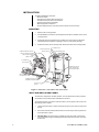
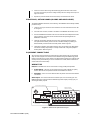
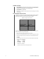
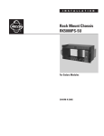
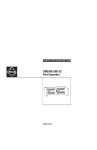
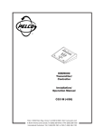
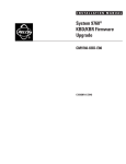
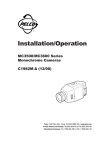
®
ERD97P21-U
Receiver
Installation/
Operation Manual
C939M-D (7/00)
Pelco • 3500 Pelco Way, Clovis • CA 93612-5699 USA • www.pelco.com
In North America and Canada: Tel (800) 289-9100 or FAX (800) 289-9150
International Customers: Tel +1 (559) 292-1981 or FAX +1 (559) 348-1120
CONTENTS
Section
Page
IMPORTANT SAFEGUARDS AND WARNINGS ................................................................ 3
DESCRIPTION ................................................................................................................... 3
INSTALLATION ................................................................................................................... 4
INPUT AND ENCLOSURE POWER .......................................................................... 4
ERD97P-AUX, OPTION BOARD (ALARMS AND AUXILIARIES) ............................. 5
EQUIPMENT CONNECTIONS .................................................................................. 5
WIRING TIPS ............................................................................................................. 5
JUMPER SETTINGS ................................................................................................. 6
VOLTAGE AND FUSING OPTIONS ........................................................................... 6
SWITCH SETTINGS .................................................................................................. 7
OPERATION ......................................................................................................................8
LENS VOLTAGE ADJUSTMENT ................................................................................ 8
MOTION COMMANDS ............................................................................................... 8
PRESETS .................................................................................................................. 8
ALARM AND AUXILIARY FUNCTIONS ..................................................................... 8
AUXILIARY OUTPUTS ............................................................................................... 8
SCANNING ................................................................................................................ 8
FRAME SCANNING .......................................................................................... 8
RANDOM SCAN ................................................................................................ 8
TROUBLESHOOTING ....................................................................................................... 9
RESET ....................................................................................................................... 9
TLC TEST MODULE .................................................................................................. 9
SERVICE MANUAL .................................................................................................... 9
SPECIFICATIONS ............................................................................................................. 10
WARRANTY AND RETURN INFORMATION ................................................................... 12
LIST OF ILLUSTRATIONS
Figure
1
2
Page
ERD97P21-U with ERD97-AUX Option Board ................................................... 4
ERD97-AUX Option Board Layout ..................................................................... 5
LIST OF TABLES
Table
A
B
2
Page
Voltage Cubes and Fuses .................................................................................. 6
Switch Settings .................................................................................................. 7
Pelco Manual C939M-D (7/00)
IMPORTANT SAFEGUARDS AND WARNINGS
Prior to installation and use of this product, the following WARNINGS should be observed.
1.
Installation and servicing should only be done by qualified service personnel and conform to all local codes.
2.
Unless the unit is specifically marked as a NEMA Type 3, 3R, 3S, 4, 4X ,6 or 6P enclosure, it is designed for indoor use only and it must not be installed where exposed to
rain and moisture.
3.
Only use replacement parts recommended by Pelco.
4.
After replacement/repair of this unit’s electrical components, conduct a resistance
measurement between line and exposed parts to verify the exposed parts have not
been connected to line circuitry.
5.
The installation method and materials should be capable of supporting four times the
weight of the receiver.
The product and/or manual may bear the following marks:
This symbol indicates that dangerous voltage constituting a risk of electric shock is
present within this unit.
This symbol indicates that there are important operating and maintenance instructions
in the literature accompanying this unit.
CAUTION:
RISK OF ELECTRIC SHOCK.
DO NOT OPEN.
Please thoroughly familiarize yourself with the information in this manual prior to installation
and operation.
DESCRIPTION
The ERD97P21-U Receiver controls one pan/tilt unit, including camera and lens functions.
The unit is designed for systems that transmit P protocol, such as CM6700 and CM9760.
Standard features include 80 presets, frame scan, and random scan.
Pelco Manual C939M-D (7/00)
3
INSTALLATION
To install the ERD97P21-U Receiver:
– Mount the receiver.
– Change the input power cable (230 VAC only).
– Connect the wiring for power to the enclosure.
– Install the option board (if applicable).
– Make all equipment connections.
– Set the voltage options for input power (pan/tilt, camera, and lens functions).
MOUNTING
1.
Determine the mounting location.
2.
Use the ERD97P21-U Receiver as a template and mark the four fastener holes onto the
mounting surface.
3.
Prepare the holes for the fasteners (not provided). Pelco recommends 1/4-20 bolts or
equivalent fasteners capable for supporting a minimum of 50 pounds (22.68 kg).
4.
Position the receiver over the mounting holes. Secure the receiver to the mounting surface.
CAMERA FUSE
INPUT POWER FUSE
ENCLOSURE FUSE
CAMERA POWER SELECTION
ON/OFF SWITCH
LENS VOLTAGE ADJUSTMENT
PC BOARD
INPUT POWER SELECTION
RESET
PRESET CLEAR
P7 CONNECTOR
DIP SWITCHES
TERMINAL STRIP FOR
INPUT POWER AND
ENCLOSURE POWER
ERD97-AUX
OPTION BOARD
TERMINAL BLOCKS FOR
EQUIPMENT CONNECTIONS
PROTECTIVE
SHIELD
GLANDS
Figure 1. ERD97P21-U with ERD97-AUX Option Board
INPUT AND ENCLOSURE POWER
The receiver is configured for 120 VAC operation. The input power and enclosure power are
connected to a terminal strip located underneath the PC board.
To change the receiver input power to 230 VAC and/or to connect power to the enclosure, do
the following. Refer to Figure 1.
4
1.
Loosen the thumbscrews on the PC board (refer to Figure 1) and move the board out of
the way.
2.
Remove the protective shield positioned over the terminal strip by loosening the thumbscrew that holds it in place.
3.
230 VAC Only - Remove the factory-installed 120 VAC power cable. Insert the 230
VAC power cable through the feedthrough gland at the base of the receiver. Connect to
terminal strip.
Pelco Manual C939M-D (7/00)
4.
Insert the enclosure cable through the feedthrough gland at the base of the receiver.
Connect to terminal strip. Enclosure voltage is always the same voltage as the input voltage to the receiver.
5.
Replace the protective shield over the terminal strip and reinstall the PC board.
ERD97P-AUX, OPTION BOARD (ALARMS AND AUXILIARIES)
To install the ERD97P-AUX board, do the following. If the ERD97P-AUX is already installed,
proceed to step 4.
1.
Locate P7, the 16-pin female connector located on the main board of the receiver. Refer to Figure 1.
2.
Insert the male connector, located on the bottom of the ERD97P-AUX board, into P7.
3.
Secure the ERD97P-AUX board to the main PC board with three Phillips head screws
and lock washers. (The three screws and lock washers were packaged with the
ERD97P21-U Receiver.)
4.
(Optional) The auxiliary switches are factory set for remote (keyboard) operation.
The option board’s auxiliary functions can be controlled manually by resetting the
Manual Auxiliary Control switches to the ON position. Refer to Figure 2.
5.
(Optional) The auxiliary output relays are factory set in the normally open (NO) position.
To reset the auxiliary output relays to normally closed mode, change the jumpers to
the NC position. Refer to Figure 2.
EQUIPMENT CONNECTIONS
All connections to the PC board and option board are made through easy-to-use terminal
strips. To make equipment connections, thread cable/wire through the feedthrough glands
located on the base of the receiver. Refer to the Wiring Table (located on the inside lid of the
receiver) and the printed labeling on the circuit boards. Use a small, slotted screwdriver to
connect wires to the terminal strip.
WIRING TIPS
Pan/Tilt –The ERD9721-U has two connections for wiring pan/tilt preset operation.
a.
SL/PP Models – Wire Pan A to the pan/tilt connection that is labeled “SL (360°)
Preset.” Wire Pan B to the pan/tilt connection that is labeled “Pan Preset.”
b.
PP Models – Pan A is not used. Wire Pan B to the pan/tilt connection that is labeled
“Pan Preset.”
Alarm Inputs – The main PC board has one alarm input, which is normally open. The
ERD970-AUX option board provides an additional eight alarm inputs (normally open), as
well as eight auxiliary outputs.
RELAY OUTPUT JUMPERS
8
K2
K1
5
6
7
D1
K3
D2
K4
D3
K5
D4
K6
D5
D8
K7
D7
K8
RN3
D6
RN2
C9
U3
U2
U1
MANUAL AUXILIARY
CONTROL SWITCHES
C1
C6
C8
4
C7
C2
C4
C5
3
C3
P9
NO NC
NO NC
NO NC
NO NC
2
NO NC
P1
1
NO NC
P8
ON
NO NC
NO NC
RN1
P11
GND
2
3
4
5
ALARMS
6
7
8
9
1+
1-
2+
2-
3+
3-
4+
4AUX
5+
5-
6+
6-
7+
7-
8+
8-
Figure 2. ERD97-AUX Option Board Layout
Pelco Manual C939M-D (7/00)
5
JUMPER SETTINGS
1.
RX Termination – To daisy chain receivers (connect two or more receivers together),
reset the RX Termination jumper to the non-terminating position. The last receiver in
the daisy chain is the terminating unit, do not reset the jumper.
2.
TX Termination – Not applicable.
3.
Alarm Out – The ERD9721-U alarm output can be set for normally open or normally
closed operation.
VOLTAGE AND FUSING OPTIONS
The ERD97P21-U Receiver can be configured to operate at 24 VAC, 120 VAC, or 230 VAC.
Seven plug-in connectors and nine fuses are included with the ERD97P21-U Receiver.
Install the proper voltage cubes and fuses. Refer to Table A and Figure 1.
Table A. Voltage Cubes and Fuses
Voltage Input Cube
Power 24V
Power 120V (Installed)
Power 230V
Camera Power 24V (Installed)
Camera Power 120/230V
Pan/Tilt Power 24V
Pan/Tilt Power 120/230V
Fuse
5A Slow Blow
2A Slow Blow (Installed)
1A Slow Blow
1A (Installed)
.2A or 1/16A
None
None
1.5A (Enclosure)*
3A (Enclosure)*
5A (Enclosure)*
*The receiver comes with three enclosure fuses (1.5A, 3A and 5A). Select the appropriate
value for your application using the following steps:
1.
Determine the full-load wattage requirements of the enclosure.
2.
Divide the enclosure wattage determined in step 1 by the input voltage to the receiver.
3.
Select a fuse value that is close to, but not less than, the value determined in step 2.
Example:
An environmental enclosure with 120 VAC input, heater, defroster and window wiper.
From the enclosure specifications:
Heater ................... 160 watts
Defroster ............... 15 watts
Window Wiper ....... 90 watts
Total wattage ......... 265 watts
265/120 VAC = 2.208 Amps
Therefore, a 3A fuse will work for this sample enclosure.
6
Pelco Manual C939M-D (7/00)
SWITCH SETTINGS
DIP switches are used to select the receiver address, the communication rate and the communication protocol. Refer to Table B.
Table B. Switch Settings
Address
1
2
3
4
5
6
7
8
9
10
11
12
13
14
15
16
17
18
19
20
21
22
23
24
25
26
27
28
29
30
31
32
1
Off
On
Off
On
Off
On
Off
On
Off
On
Off
On
Off
On
Off
On
Off
On
Off
On
Off
On
Off
On
Off
On
Off
On
Off
On
Off
On
Switch Setting
2
3
4
Off Off Off
Off Off Off
On Off Off
On Off Off
Off On Off
Off On Off
On On Off
On On Off
Off Off On
Off Off On
On Off On
On Off On
Off On On
Off On On
On On On
On On On
Off Off Off
Off Off Off
On Off Off
On Off Off
Off On Off
Off On Off
On On Off
On On Off
Off Off On
Off Off On
On Off On
On Off On
Off On On
Off On On
On On On
On On On
5
Off
Off
Off
Off
Off
Off
Off
Off
Off
Off
Off
Off
Off
Off
Off
Off
On
On
On
On
On
On
On
On
On
On
On
On
On
On
On
On
Communication Switch Setting
Rate
6
7
1200 Baud
2400 Baud
4800 Baud
9600 Baud
Protocol
Reserved
P Protocol
Pelco Manual C939M-D (7/00)
Off
On
Off
On
Off
Off
On
On
Switch Setting
8
Off
On
7
OPERATION
The ERD97P21-U Receiver runs a configuration cycle at startup to detect preset capabilities and verify that the unit functions properly.
To start the receiver, plug it in. Set the ON/OFF switch to ON. The pan/tilt unit tilts down and
pans left, followed by a tilt up and a pan to the right. The lens zooms out and focuses far.
The lens zooms in and focuses near. During the configuration cycle, the receiver will not accept any commands.
LENS VOLTAGE ADJUSTMENT
The lens voltage is adjusted manually by turning a potentiometer on the PC board. Refer to
Figure 1. The range of adjustment is from 5 VDC to 10 VDC.
MOTION COMMANDS
Motion commands tell the receiver to start or stop a pan/tilt or lens motion. More than one
motion command can be requested at a time. There is a 60-second timeout on all motion
commands. If the receiver initiates a motion and no commands are received for 60 seconds,
the receiver stops all motion. This prevents the receiver from being driven continuously if
communication problems arise.
PRESETS
The ERD97P21-U can store up to 80 presets. (To set presets, refer to the instruction
manual for the control unit.) All presets are cleared if the preset clear switch is pressed and
held down while the processor is either reset or powered up.
If any motion command or alarm is received during a move to a preset position, the command is aborted and the new command is initiated.
ALARM AND AUXILIARY FUNCTIONS
The alarm inputs are reserved for the first nine presets. If an alarm becomes active and
there is a preset for the alarm, the preset is initiated. For example, if alarm 4 is activated,
the camera moves to preset 4. If more than one alarm is activated, the receiver sequences
between the corresponding presets, stopping for five seconds at each preset.
If a motion command or move to preset command is received while alarms are active,
alarm processing stops and the command is processed. After 60 seconds, alarm processing resumes. The alarm lockout timer is reset if all alarms become inactive. Alarm processing restarts immediately if an alarm is triggered.
AUXILIARY OUTPUTS
There are eight auxiliary outputs on the optional alarm/auxiliary board. These relays are
opened and closed by receiver software commands.
SCANNING
FRAME SCANNING
To start frame scanning, call preset 98.
To stop frame scanning, call preset 96.
Panning motion is not continuous during frame scanning operation. The receiver moves the
pan/tilt unit to the right for three seconds, stops for three seconds, pans to the right again
for three seconds. When the unit hits a limit stop, it reverses direction.
If any motion command or alarm is requested during frame scan, the scanning is aborted
and the new command is initiated.
8
Pelco Manual C939M-D (7/00)
RANDOM SCAN
To start random scanning, call preset 97.
To stop random scanning, call preset 96.
When random scanning starts, the pan/tilt unit moves to the left for 60 seconds or until it
hits a limit stop. When a limit stop is hit, the unit pans to the right for 60 seconds or until it
hits a limit stop. The receiver then starts a random cycle of movement, panning and stopping for a random amount of time.
If there are no limit stops, the movement time varies between 1 and 60 seconds. If there are
limit stops, the movement time varies between 1 second and the time it takes to move between the limit stops. The time between movement varies from 4 to 60 seconds. If any motion command or alarm is received during random scan, the scan is aborted.
TROUBLESHOOTING
RESET
If the receiver settings are changed (for example, DIP switch or voltage settings) or if the
unit locks up, press the reset button located on the main PC board. Refer to Figure 1.
The reset command starts the receiver’s configuration cycle. The pan/tilt unit tilts down and
pans left, followed by a tilt up and a pan to the right. The lens zooms out and focuses far.
The lens zooms in and focuses near. The receiver will not accept any commands during the
configuration cycle.
SERVICE MANUAL
If you need to service your unit, obtain a service manual in one of the following ways:
•
Go to Pelco’s web site at ftp://www.pelco.com and find service manual C939SM.
•
Call Pelco’s DataFAX service at 1-800-289-9108 or 1-559-292-04335 and request
document 29398.
•
Contact Pelco’s Literature Department and request service manual C939SM.
Pelco Manual C939M-D (7/00)
9
SPECIFICATIONS
ELECTRICAL
Input Voltage:
24 VAC, 120 VAC, 230 VAC (selected with labeled plug-in connectors)
Pan/Tilt Voltage:
24 VAC (2A maximum), 120 VAC, 230 VAC (selected with labeled plugin connectors; no voltage step-up possible; with 230 VAC input, not
possible to step down to 120 VAC)
Camera Voltage:
24 VAC (0.5 A maximum), 120 VAC, 230 VAC (selected with labeled
plug-in connectors; no voltage step-up possible; with 230 VAC input,
not possible to step down to 120 VAC).
Enclosure Voltage: Follows input voltage to receiver, fused.
Lens Voltage:
6 to 10 VDC; 25 mA at 10 VDC and 100 mA at 9 VDC
Power Consumption
Pan/Tilt:
48 vA maximum
Camera:
12 vA maximum
Lens:
5 vA maximum
Receiver:
15 vA maximum
Total:
80 vA maximum
Control Method:
RS-422 compatible (at 1200, 2400, 4800, 9600 baud). Receiver address and baud rate selectable by DIP switch.
Alarm Inputs:
Main PC board has 1 normally open alarm input.
Option board has 8 additional normally open alarm inputs
Relay Outputs:
Main PC board has 1 relay. Option board has additional 8 relay outputs, which are under receiver control or manual control via DIP switch.
(All relay outputs can be set for normally closed or normally open operation.)
Contact Rating:
1A at 24 VDC, 0.5 A at 120 VAC
Random Scan:
Yes
Frame Scan:
Yes
Presets:
Standard with all units, 80 presets maximum
LED Indicators:
Power, TX data, RX data
Fuse Protection
Receiver Input
Power:
10
24 VAC – 5 ASB
120 VAC – 2 ASB
230 VAC – 1 ASB
Camera Power:
24 VAC – 1.0 A
120 VAC – 0.2 A
230 VAC – 1/16 A
Enclosure Power:
Fuse values depend on the specifications of the equipment/accessories
installed in the enclosure. Check equipment specifications for determining fuse values.
Pelco Manual C939M-D (7/00)
GENERAL
Operating
Temperature:
14° to 122°F (-10° to 50°C)
Dimensions:
9.44 (W) x 4.32 (H) x 11.62 (D) inches
(23.98 x 10.97 x 29.51 cm)
Weight:
12 lb (5.43 kg)
Rating:
NEMA 4X
(Design and product specifications subject to change without notice.)
Pelco Manual C939M-D (7/00)
11
PRODUCT WARRANTY AND RETURN INFORMATION
WARRANTY
Pelco will repair or replace, without charge, any merchandise proved defective in material or
workmanship for a period of one year after the date of shipment.
Exceptions to this warranty are as noted below:
• Five years on FT/FR8000 Series fiber optic products.
• Three years on Genex ® Series products (multiplexers, server, and keyboard).
• Three years on Camclosure ® and fixed camera models, except the CC3701H-2,
CC3701H-2X, CC3751H-2, CC3651H-2X, MC3651H-2, and MC3651H-2X camera models,
which have a five-year warranty.
• Two years on standard motorized or fixed focal length lenses.
• Two years on Legacy ®, CM6700/CM6800/CM9700 Series matrix, and DF5/DF8 Series
fixed dome products.
®
®
™
• Two years on Spectra , Esprit , ExSite , and PS20 scanners, including when used in
continuous motion applications.
• Two years on Esprit ® and WW5700 Series window wiper (excluding wiper blades).
• Eighteen months on DX Series digital video recorders, NVR300 Series network video
recorders, and Endura ™ Series distributed network-based video products.
• One year (except video heads) on video cassette recorders (VCRs). Video heads will be
covered for a period of six months.
• Six months on all pan and tilts, scanners or preset lenses used in continuous motion
applications (that is, preset scan, tour and auto scan modes).
Pelco will warrant all replacement parts and repairs for 90 days from the date of Pelco
shipment. All goods requiring warranty repair shall be sent freight prepaid to Pelco, Clovis,
California. Repairs made necessary by reason of misuse, alteration, normal wear, or accident
are not covered under this warranty.
Pelco assumes no risk and shall be subject to no liability for damages or loss resulting from
the specific use or application made of the Products. Pelco’s liability for any claim, whether
based on breach of contract, negligence, infringement of any rights of any party or product
liability, relating to the Products shall not exceed the price paid by the Dealer to Pelco for
such Products. In no event will Pelco be liable for any special, incidental or consequential
damages (including loss of use, loss of profit and claims of third parties) however caused,
whether by the negligence of Pelco or otherwise.
The above warranty provides the Dealer with specific legal rights. The Dealer may also have
additional rights, which are subject to variation from state to state.
If a warranty repair is required, the Dealer must contact Pelco at (800) 289-9100 or
(559) 292-1981 to obtain a Repair Authorization number (RA), and provide the following
information:
1. Model and serial number
2. Date of shipment, P.O. number, Sales Order number, or Pelco invoice number
3. Details of the defect or problem
If there is a dispute regarding the warranty of a product which does not fall under the
warranty conditions stated above, please include a written explanation with the product
when returned.
Method of return shipment shall be the same or equal to the method by which the item was
received by Pelco.
RETURNS
In order to expedite parts returned to the factory for repair or credit, please call the factory at
(800) 289-9100 or (559) 292-1981 to obtain an authorization number (CA number if returned
for credit, and RA number if returned for repair).
All merchandise returned for credit may be subject to a 20% restocking and refurbishing
charge.
Goods returned for repair or credit should be clearly identified with the assigned CA or RA
number and freight should be prepaid. Ship to the appropriate address below.
If you are located within the continental U.S., Alaska, Hawaii or Puerto Rico, send goods to:
Service Department
Pelco
3500 Pelco Way
Clovis, CA 93612-5699
If you are located outside the continental U.S., Alaska, Hawaii or Puerto Rico and are
instructed to return goods to the USA, you may do one of the following:
If the goods are to be sent by a COURIER SERVICE, send the goods to:
Pelco
3500 Pelco Way
Clovis, CA 93612-5699 USA
If the goods are to be sent by a FREIGHT FORWARDER, send the goods to:
Pelco c/o Expeditors
473 Eccles Avenue
South San Francisco, CA 94080 USA
Phone: 650-737-1700
Fax: 650-737-0933
REVISION HISTORY
Manual #
C939M
C939M-A
C939M-B
C939M-C
Date
11/95
12/95
5/96
12/99
C939M-D
7/00
Comments
Original manual.
Fusing information updated.
Updated per ECO#95-468. Changed exploded view and parts call-out.
Revised range for lens voltage adjustment. Moved exploded assembly diagram and parts lists to new maintenance/service
manual (C939SM). Updated manual to new format.
Removed references to LRD41TLC.
Pelco, the Pelco logo, Camclosure, Esprit, Genex, Legacy, and Spectra are registered trademarks of Pelco.
Endura and ExSite are trademarks of Pelco.
12
© Copyright 2000, Pelco.
All rights reserved.
Pelco Manual C939M-D (7/00)