1
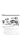
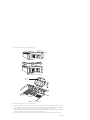
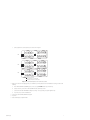
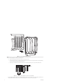
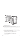
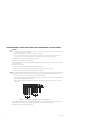
INSTALLATION/OPERATION
CM9700-SER-32
Port Expander
C579M-A (5/05)
Contents
Regulatory Notices . . . . . . . . . . . . . . . . . . . . . . . . . . . . . . . . . . . . . . . . . . . . . . . . . . . . . . . . . . . . . . . . . . . . . . . . . . . . . . . . . . . . . . . . . . . . . . . . . . . .4
Installation . . . . . . . . . . . . . . . . . . . . . . . . . . . . . . . . . . . . . . . . . . . . . . . . . . . . . . . . . . . . . . . . . . . . . . . . . . . . . . . . . . . . . . . . . . . . . . . . . . . . . . . . . .5
4 Sercom Cards, 1 Rocket Port Card (64 Total Ports) . . . . . . . . . . . . . . . . . . . . . . . . . . . . . . . . . . . . . . . . . . . . . . . . . . . . . . . . . . . . . . . . . . . . .5
4 Sercom Cards, 2 Rocket Port Cards, Com 2 Unavailable (96 Total Ports) . . . . . . . . . . . . . . . . . . . . . . . . . . . . . . . . . . . . . . . . . . . . . . . . . . . .8
3 Sercom Cards, 2 Rocket Port Cards, Com 2 Available (88 Total Ports) . . . . . . . . . . . . . . . . . . . . . . . . . . . . . . . . . . . . . . . . . . . . . . . . . . . . . .9
3 Sercom Cards, 3 Rocket Port Cards, Com 2 Unavailable (120 Total Ports) . . . . . . . . . . . . . . . . . . . . . . . . . . . . . . . . . . . . . . . . . . . . . . . . . .12
List of Illustrations
1
2
3
4
5
6
7
8
C579M-A (5/05)
CM9700-SER-32 Assembly Detail . . . . . . . . . . . . . . . . . . . . . . . . . . . . . . . . . . . . . . . . . . . . . . . . . . . . . . . . . . . . . . . . . . . . . . . . . . . . . . . . . . . .5
Removing the CC1 Top Cover. . . . . . . . . . . . . . . . . . . . . . . . . . . . . . . . . . . . . . . . . . . . . . . . . . . . . . . . . . . . . . . . . . . . . . . . . . . . . . . . . . . . . . . .6
CC1 Internal Layout. . . . . . . . . . . . . . . . . . . . . . . . . . . . . . . . . . . . . . . . . . . . . . . . . . . . . . . . . . . . . . . . . . . . . . . . . . . . . . . . . . . . . . . . . . . . . . . .6
Rocket Card to Expansion Port Control Association. . . . . . . . . . . . . . . . . . . . . . . . . . . . . . . . . . . . . . . . . . . . . . . . . . . . . . . . . . . . . . . . . . . . . . .7
Sercom Card Mounting Plate Removal. . . . . . . . . . . . . . . . . . . . . . . . . . . . . . . . . . . . . . . . . . . . . . . . . . . . . . . . . . . . . . . . . . . . . . . . . . . . . . . .10
Sercom/PCI Card Configuration for 88 Ports, Com 2 Available . . . . . . . . . . . . . . . . . . . . . . . . . . . . . . . . . . . . . . . . . . . . . . . . . . . . . . . . . . . . .10
CM9700-ADP-120 Adapter Plate Installation. . . . . . . . . . . . . . . . . . . . . . . . . . . . . . . . . . . . . . . . . . . . . . . . . . . . . . . . . . . . . . . . . . . . . . . . . . .11
Sercom/PCI Card Configuration for 120 Ports, Com 2 Unavailable . . . . . . . . . . . . . . . . . . . . . . . . . . . . . . . . . . . . . . . . . . . . . . . . . . . . . . . . . .12
3
Regulatory Notices
This device complies with Part 15 of the FCC Rules. Operation is subject to the following two conditions: (1) this device may not cause harmful
interference, and (2) this device must accept any interference received, including interference that may cause undesired operation.
RADIO AND TELEVISION INTERFERENCE
This equipment has been tested and found to comply with the limits of a Class A digital device, pursuant to Part 15 of the FCC Rules. These limits
are designed to provide reasonable protection against harmful interference when the equipment is operated in a commercial environment. This
equipment generates, uses, and can radiate radio frequency energy and, if not installed and used in accordance with the instruction manual, may
cause harmful interference to radio communications. Operation of this equipment in a residential area is likely to cause harmful interference in
which case the user will be required to correct the interference at his own expense.
Changes and modifications not expressly approved by the manufacturer or registrant of this equipment can void your authority to operate this
equipment under Federal Communications Commission’s rules.
This Class A digital apparatus complies with Canadian ICES-003.
Cet appareil numérique de la classe A est conforme à la norme NMB-003 du Canada.
4
C579M-A (5/05)
Installation
The CM9700-SER-32 port expander assembly increases by 32 the number of available Sercom (serial communication) ports in a node-based
CM9700-CC1 via the installation of an RP (rocket port) PCI expansion card. A maximum of 120 total ports can be achieved by using three
CM9700-SER-32 assemblies in conjunction with the Sercom cards in the CC1. Refer to Figure 1 for assembly detail.
422
PCI EXPANSION CARD (1)
(ROCKET PORT CARD)
RS-232/422 SWITCH (32)
COMM INTERFACE FOR EACH
CONNECTOR IS SET BY THIS
SWITCH. UP IS RS-422;
DOWN IS RS-232
232
HOST CONNECTIONS
CM9700-ADP-120
ADAPTER BRACKET
FOR USE WITH RP CARD
IN PCI SLOT 1.
CONNECTING DATA CABLE (2)
ONE SET OF CONNECTING DATA
CABLES IS PROVIDED. EACH
CABLE IS THREE FEET LONG.
ADAPTER DB25 TO RJ-45 (32)
Figure 1. CM9700-SER-32 Assembly Detail
4 SERCOM CARDS, 1 ROCKET PORT CARD (64 TOTAL PORTS)
WARNINGS:
•
Software version 9.03.007 or higher must be installed in the CC1 to enable port expansion ability. If running a previous version, contact Pelco
for software upgrade kit options and availability.
•
Failure to turn off the CC1 power could result in serious damage to the equipment.
•
Electrostatic discharge (ESD) precautions must be observed when performing the procedures described in this manual. Always wear a
gounding strap connected to an approved grounding source when working on or around exposed electronic components.
1. Turn off all power to the CC1. Disconnect and label all attached cabling.
2. Install the RP card into the CC1. Refer to Figure 2 and Figure 3 and do the following:
a.
Remove the top cover mounting screws.
b.
From the rear, tilt the top cover up at a slight angle, and then pull backwards away from the front edge to remove the cover from the
CC1 chassis.
NOTE: If the VGA card is present in PCI slot 2, remove the retaining screw and gently pull the card up. Reinstall the card into PCI slot 4 (follow
steps c and d, applying them to the VGA card and PCI slot 4).
C579M-A (5/05)
c.
Remove the retaining screw and slot cover for PCI slot 2. Slide the cover out.
d.
Install the RP card into PCI slot 2. Carefully align the gold-fingered edge connector of the RP card with the PCI slot. Gently but firmly
press the RP card down until fully seated into the PCI slot. Reinstall the retaining screw to secure the RP card into place.
5
e.
Reinstall the top cover and secure with mounting screws.
Figure 2. Removing the CC1 Top Cover
RETAINING
SCREW
COVER
ISA
SLOTS
PCI
EXPANSION
SLOTS
Figure 3. CC1 Internal Layout
3. Mount external hardware. Refer to Figure 1 and do the following:
6
a.
Mount the port expansion unit so that the two supplied data cables will reach the CC1 unit. The data cables are three feet in length.
b.
Connect the male end of one data cable to the bottom DB26 connector of the RP card installed in the CC1. Connect the other (female)
end to the DB25 host connector for the second grouping of 16 ports on the right side of the port expansion unit.
c.
Connect the male end of the remaining data cable to the top DB26 connector of the RP card. Connect the other end to the DB25 host
connector for the first grouping of 16 ports on the left side of the port expansion unit.
d.
If using RS-232 operation, set the switch located to the right of each port used on the port expansion unit to the “232” position.
C579M-A (5/05)
e.
Connect peripherals to desired expansion ports. Refer to RP1 in Figure 4.
RP 1
RP 2
112
110
RP 3
113
111
109
125
115
116
114
102
104
117
107
105
103
129
128
131
130
132
B
T
101
127
126
92
90
88
86
76
74
72
70
91
89
87
85
75
73
71
100
B
T
69
98
96
94
84
82
80
78
99
97
95
93
60
58
56
54
83
81
79
77
59
57
55
44
42
40
38
64
53
43
41
39
68
66
B
T
37
62
52
50
48
46
67
65
63
61
51
49
47
45
106
108
119
118
121
120
123
122
124
T = Top connector on rocket card
B = Bottom connector on rocket card
Figure 4. Rocket Card to Expansion Port Control Association
4. Apply power to the CC1. After applying power, press the Delete key on the keyboard to enter into the BIOS menu settings, and then do the
following:
a.
After “ENTER CURRENT PASSWORD” appears on the screen, type PELCON and then press the Enter key.
b.
Using the arrow key, scroll down to PCI PLUG AND PLAY SETUP, and then press Enter.
c.
Scroll down to PCI SLOT 2 IRQ PRIORITY. Change the setting to “15” by repeatedly pressing the Page Down key.
d.
Press the Esc key to return to the BIOS menu.
5. Scroll down to SAVE SETTINGS AND EXIT and type Y
6. Press Enter.
7. Reboot machine by pressing Ctrl+Alt+Del.
C579M-A (5/05)
7
4 SERCOM CARDS, 2 ROCKET PORT CARDS, COM 2 UNAVAILABLE (96 TOTAL PORTS)
WARNING:
•
Software version 9.03.007 or higher must be installed in the CC1 to enable port expansion ability. If running a previous version, contact Pelco
for software upgrade kit options and availability.
•
Failure to turn off the CC1 power could result in serious damage to the equipment.
•
Electrostatic discharge (ESD) precautions must be observed when performing the procedures described in this manual. Always wear a
gounding strap connected to an approved grounding source when working on or around exposed electronic components.
1. Turn off all power to the CC1. Disconnect and label all attached cabling.
2. Install the RP cards into the CC1. Refer to Figure 2 and Figure 3 and do the following:
a.
Remove the top cover mounting screws.
b.
From the rear, tilt the top cover up at a slight angle, and then pull backwards away from the front edge to remove the cover from the
CC1 chassis.
NOTE: This configuration mandates that the VGA card be installed in PCI slot 4. If present in any other PCI slot, remove the retaining screw and
gently pull the card up. Reinstall the card into PCI slot 4 (follow steps c and d, applying them to the VGA card and PCI slot 4).
c.
Remove the retaining screw and slot cover for PCI slots 2 and 3. Slide both covers out.
d.
Install an RP card into PCI slot 2. Carefully align the gold-fingered edge connector of the RP card with the PCI slot. Gently but firmly
press the RP card down until fully seated into the PCI slot. Reinstall the retaining screw to secure the RP card into place.
e.
Repeat step d for installing the second RP card into PCI slot 3.
3. Reinstall the top cover and secure with mounting screws.
4. Mount external hardware. Refer to Figure 1 and do the following:
NOTE: This procedure is for each individual port expansion assembly (one RP card and port expansion unit) and is to be duplicated for each RP
card installed in the CM9700-CC1. Power should not be applied until all physical connections have been secured.
a.
Mount the port expansion unit so that the two supplied data cables will reach the CC1 unit. The data cables are three feet in length.
b.
Connect the male end of one data cable to the bottom DB26 connector of the RP card installed in the CC1. Connect the other (female)
end to the DB25 host connector for the second grouping of 16 ports on the right side of the port expansion unit.
c.
Connect the male end of the remaining data cable to the top DB26 connector of the RP card. Connect the other end to the DB25 host
connector for the first grouping of 16 ports on the left side of the port expansion unit.
d.
If using RS-232 operation, set the switch located to the right of each port used on the port expansion unit to the “232” position.
5. Connect peripherals to desired expansion ports. Refer to RP1 and RP2 in Figure 4.
6. Apply power to the CC1. After applying power, press the Delete key on the keyboard to enter into the BIOS menu settings, and then do the
following:
a.
After “ENTER CURRENT PASSWORD” appears on the screen, type PELCON and then press the Enter key.
b.
Using the arrow key, scroll down to PCI PLUG AND PLAY SETUP, and then press Enter.
c.
Scroll down to PCI SLOT 2 IRQ PRIORITY. Change the setting to “15” by repeatedly pressing the Page Down key.
d.
Scroll down to PCI SLOT 3 IRQ PRIORITY. Change the setting to “3” by repeatedly pressing Page Down.
7. Press the Esc key to return to the BIOS menu.
8
C579M-A (5/05)
8. Scroll down to PERIPHERAL SETTINGS, press Enter, and then do the following:
a.
Scroll down to ONBOARD SERIAL PORT 2.
b.
Change the setting to DISABLED by pressing Page Down.
c.
Press Esc.
d.
Scroll down to SAVE SETTINGS AND EXIT and type Y
e.
Press Enter.
9. Reboot machine by pressing Ctrl+Alt+Del.
3 SERCOM CARDS, 2 ROCKET PORT CARDS, COM 2 AVAILABLE (88 TOTAL PORTS)
WARNING:
•
Software version 9.03.007 or higher must be installed in the CC1 to enable port expansion ability. If running a previous version, contact Pelco
for software upgrade kit options and availability.
•
Failure to turn off the CC1 power could result in serious damage to the equipment.
•
Electrostatic discharge (ESD) precautions must be observed when performing the procedures described in this manual. Always wear a
gounding strap connected to an approved grounding source when working on or around exposed electronic components.
1. Turn off all power to the CC1. Disconnect and label all attached cabling.
2. Remove the top cover mounting screws (refer to Figure 2).
3. From the rear, tilt the top cover up at a slight angle, and then pull backwards away from the front edge to remove the cover from the CC1
chassis (refer to Figure 2).
4. Install the RP cards into the CC1.
C579M-A (5/05)
a.
Remove the screws securing the Sercom card mounting plate (refer to Figure 5).
b.
Remove the Sercom card mounting plate by gently pulling outward from the CC1 chassis (refer to Figure 5).
c.
Remove the Sercom card from ISA slot 4 by gently pulling up (refer to Figure 3). This card will not be used and should be stored in an
ESD-safe container.
9
Figure 5. Sercom Card Mounting Plate Removal
NOTE: If the VGA card is present in PCI slot 2, remove the retaining screw and gently pull the card up. Reinstall the card into PCI slot 4 (follow
steps d, e, and f, applying them to the VGA card and PCI slot 4).
d.
Remove the retaining screw and slot cover for PCI slot 2. Slide the cover out.
e.
Install an RP card into PCI slot 1. Carefully align the gold-fingered edge connector of the RP card with the PCI slot. Gently but firmly
press the RP card down until fully seated into the PCI slot.
f.
Repeat step e for installing the second RP card into PCI slot 2. Reinstall the retaining screw to secure the RP card into place.
VGA CARD
1
2
3
4
RP CARDS
SERCOM
CARDS
Figure 6. Sercom/PCI Card Configuration for 88 Ports, Com 2 Available
5. Install the CM9700-ADP-120 adapter plate. Carefully align the plate with the front of the three Sercom cards and the RP card in PCI slot 1
while pushing in toward the CC1 chassis. Secure with mounting plate screws removed earlier. Refer to Figure 7.
10
C579M-A (5/05)
Figure 7. CM9700-ADP-120 Adapter Plate Installation
6. Reinstall the top cover and secure with mounting screws.
7. Mount external hardware. Refer to Figure 1 and do the following:
NOTE: This procedure is for each individual port expansion assembly (one RP card and port expansion unit) and is to be duplicated for each RP
card installed in the CM9700-CC1. Power should not be applied until all physical connections have been secured.
a.
Mount the port expansion unit so that the two supplied data cables will reach the CC1 unit. The data cables are three feet in length.
b.
Connect the male end of one data cable to the bottom DB26 connector of the RP card installed in the CC1. Connect the other (female)
end to the DB25 host connector for the second grouping of 16 ports on the right side of the port expansion unit.
c.
Connect the male end of the remaining data cable to the top DB26 connector of the RP card. Connect the other end to the DB25 host
connector for the first grouping of 16 ports on the left side of the port expansion unit.
d.
If using RS-232 operation, set the switch located to the right of each port used on the port expansion unit to the “232” position.
8. Connect peripherals to desired expansion ports. Refer to RP1 and RP2 in Figure 4.
9. Apply power to the CC1. After applying power, press the Delete key on the keyboard to enter into the BIOS menu settings, and then do the
following:
a.
After “ENTER CURRENT PASSWORD” appears on the screen, type PELCON and then press the Enter key.
b.
Using the arrow key, scroll down to PCI PLUG AND PLAY SETUP, and then press Enter.
c.
Scroll down to PCI SLOT 1 IRQ PRIORITY. Change the setting to “5” by repeatedly pressing the Page Down key.
d.
Scroll down to PCI SLOT 2 IRQ PRIORITY. Change the setting to “15” by repeatedly pressing Page Down.
10. Press the Esc key to return to the BIOS menu.
11. Reboot machine by pressing Ctrl+Alt+Del.
C579M-A (5/05)
11
3 SERCOM CARDS, 3 ROCKET PORT CARDS, COM 2 UNAVAILABLE (120 TOTAL PORTS)
WARNING:
•
Software version 9.03.007 or higher must be installed in the CC1 to enable port expansion ability. If running a previous version, contact Pelco
for software upgrade kit options and availability.
•
Failure to turn off the CC1 power could result in serious damage to the equipment.
•
Electrostatic discharge (ESD) precautions must be observed when performing the procedures described in this manual. Always wear a
gounding strap connected to an approved grounding source when working on or around exposed electronic components.
1. Turn off all power to the CC1. Disconnect and label all attached cabling.
2. Remove the top cover mounting screws (refer to Figure 2).
3. From the rear, tilt the top cover up at a slight angle, and then pull backwards away from the front edge to remove the cover from the CC1
chassis (refer to Figure 2).
4. Install the RP cards into the CC1.
a.
Remove the screws securing the Sercom card mounting plate (refer to Figure 5).
b.
Remove the Sercom card mounting plate by gently pulling outward from the CC1 chassis (refer to Figure 5).
c.
Remove the Sercom card from ISA slot 4 by gently pulling up (refer to Figure 3).
NOTE: This configuration mandates that the VGA card be installed in PCI slot 4. If present in any other PCI expansion slot, remove the retaining
screw and gently pull the card up. Reinstall the card into PCI slot 4 (follow steps d, e, and f, applying them to the VGA card and PCI slot 4).
d.
Remove the retaining screw and slot cover for PCI slot 2 and 3. Slide both covers out.
e.
Install an RP card into PCI slot 1. Carefully align the gold-fingered edge connector of the RP card with the PCI slot. Gently but firmly
press RP card down until fully seated into the PCI slot.
f.
Repeat step e for installing the second and third RP cards into PCI slots 2 and 3. Reinstall the retaining screws to secure these RP
cards into place.
VGA CARD
1
2
3
4
RP CARDS
SERCOM
CARDS
Figure 8. Sercom/PCI Card Configuration for 120 Ports, Com 2 Unavailable
5. Install the CM9700-ADP-120 adapter plate. Carefully align the plate with the front of the three Sercom cards and the RP card in PCI slot 1
while pushing in toward the CC1 chassis. Secure with mounting plate screws removed earlier. Refer to Figure 7.
6. Reinstall the top cover and secure with mounting screws.
12
C579M-A (5/05)
7. Mount external hardware. Refer to Figure 1 and do the following:
NOTE: This procedure is for each individual port expansion assembly (one RP card and port expansion unit) and is to be duplicated for each RP
card installed in the CM9700-CC1. Power should not be applied until all physical connections have been secured.
a.
Mount the port expansion unit so that the two supplied data cables will reach the CC1 unit. The data cables are three feet in length.
b.
Connect the male end of one data cable to the bottom DB26 connector of the RP card installed in the CC1. Connect the other (female)
end to the DB25 host connector for the second grouping of 16 ports on the right side of the port expansion unit.
c.
Connect the male end of the remaining data cable to the top DB26 connector of the RP card. Connect the other end to the DB25 host
connector for the first grouping of 16 ports on the left side of the port expansion unit.
d.
If using RS-232 operation, set the switch located to the right of each port used on the port expansion unit to the “232” position.
8. Connect peripherals to desired expansion ports. Refer to RP1, RP2, and RP3 in Figure 4.
9. Apply power to the CC1. After applying power, press the Delete key on the keyboard to enter into the BIOS menu settings, and then do the
following:
a.
After “ENTER CURRENT PASSWORD” appears on the screen, type PELCON and then press the Enter key.
b.
Using the arrow key, scroll down to PCI PLUG AND PLAY SETUP, and then press Enter.
c.
Scroll down to PCI SLOT 1 IRQ PRIORITY. Change the setting to “5” by repeatedly pressing the Page Down key.
d.
Scroll down to PCI SLOT 2 IRQ PRIORITY. Change the setting to “15” by repeatedly pressing Page Down.
e.
Scroll down to PCI SLOT 3 IRQ PRIORITY. Change the setting to “3” by repeatedly pressing Page Down.
10. Press the Esc key to return to the BIOS menu.
11. Scroll down to PERIPHERAL SETTINGS, press Enter, and then do the following:
a.
Scroll down to ONBOARD SERIAL PORT 2.
b.
Change the setting to DISABLED by pressing Page Down.
c.
Press Esc.
d.
Scroll down to SAVE SETTINGS AND EXIT and type Y
e.
Press Enter.
12. Reboot machine by pressing Ctrl+Alt+Del.
C579M-A (5/05)
13
14
C579M-A (5/05)
PRODUCT WARRANTY AND RETURN INFORMATION
WARRANTY
Pelco will repair or replace, without charge, any merchandise proved defective in material or
workmanship for a period of one year after the date of shipment.
Exceptions to this warranty are as noted below:
• Five years on FT/FR8000 Series fiber optic products.
• Three years on Genex ® Series products (multiplexers, server, and keyboard).
• Three years on Camclosure ® and fixed camera models, except the CC3701H-2,
CC3701H-2X, CC3751H-2, CC3651H-2X, MC3651H-2, and MC3651H-2X camera models,
which have a five-year warranty.
• Two years on standard motorized or fixed focal length lenses.
• Two years on Legacy ®, CM6700/CM6800/CM9700 Series matrix, and DF5/DF8 Series
fixed dome products.
• Two years on Spectra ®, Esprit®, ExSite™, and PS20 scanners, including when used in
continuous motion applications.
• Two years on Esprit ® and WW5700 Series window wiper (excluding wiper blades).
• Eighteen months on DX Series digital video recorders, NVR300 Series network video
recorders, and Endura ™ Series distributed network-based video products.
• One year (except video heads) on video cassette recorders (VCRs). Video heads will be
covered for a period of six months.
• Six months on all pan and tilts, scanners or preset lenses used in continuous motion
applications (that is, preset scan, tour and auto scan modes).
Pelco will warrant all replacement parts and repairs for 90 days from the date of Pelco
shipment. All goods requiring warranty repair shall be sent freight prepaid to Pelco, Clovis,
California. Repairs made necessary by reason of misuse, alteration, normal wear, or accident
are not covered under this warranty.
Pelco assumes no risk and shall be subject to no liability for damages or loss resulting from
the specific use or application made of the Products. Pelco’s liability for any claim, whether
based on breach of contract, negligence, infringement of any rights of any party or product
liability, relating to the Products shall not exceed the price paid by the Dealer to Pelco for
such Products. In no event will Pelco be liable for any special, incidental or consequential
damages (including loss of use, loss of profit and claims of third parties) however caused,
whether by the negligence of Pelco or otherwise.
The above warranty provides the Dealer with specific legal rights. The Dealer may also have
additional rights, which are subject to variation from state to state.
If a warranty repair is required, the Dealer must contact Pelco at (800) 289-9100 or
(559) 292-1981 to obtain a Repair Authorization number (RA), and provide the following
information:
1. Model and serial number
2. Date of shipment, P.O. number, Sales Order number, or Pelco invoice number
3. Details of the defect or problem
If there is a dispute regarding the warranty of a product which does not fall under the
warranty conditions stated above, please include a written explanation with the product
when returned.
Method of return shipment shall be the same or equal to the method by which the item was
received by Pelco.
RETURNS
In order to expedite parts returned to the factory for repair or credit, please call the factory at
(800) 289-9100 or (559) 292-1981 to obtain an authorization number (CA number if returned
for credit, and RA number if returned for repair).
All merchandise returned for credit may be subject to a 20% restocking and refurbishing
charge.
Goods returned for repair or credit should be clearly identified with the assigned CA or RA
number and freight should be prepaid. Ship to the appropriate address below.
If you are located within the continental U.S., Alaska, Hawaii or Puerto Rico, send goods to:
Service Department
Pelco
3500 Pelco Way
Clovis, CA 93612-5699
If you are located outside the continental U.S., Alaska, Hawaii or Puerto Rico and are
instructed to return goods to the USA, you may do one of the following:
If the goods are to be sent by a COURIER SERVICE, send the goods to:
Pelco
3500 Pelco Way
Clovis, CA 93612-5699 USA
If the goods are to be sent by a FREIGHT FORWARDER, send the goods to:
Pelco c/o Expeditors
473 Eccles Avenue
South San Francisco, CA 94080 USA
Phone: 650-737-1700
Fax: 650-737-0933
REVISION HISTORY
Manual #
C579M
C579M-A
Date
8/02
5/05
Comments
Original version.
Changed CM9760 reference to CM9700. Manual updated to include CM9700-ADP-120 adapter plate, and revised installation instructions.
Pelco, the Pelco logo, Camclosure, Esprit, Genex, Legacy, and Spectra are registered trademarks of Pelco.
Endura and ExSite are trademarks of Pelco.
©Copyright 2005, Pelco. All rights reserved.
Worldwide Headquarters
3500 Pelco Way
Clovis, California 93612 USA
USA & Canada
Tel: 800/289-9100
Fax: 800/289-9150
International
Tel: 1-559/292-1981
Fax: 1-559/348-1120
www.pelco.com
ISO9001
United States
|
Canada
|
United Kingdom
|
The Netherlands
| Singapore | Spain | Scandinavia | France | Middle East