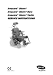
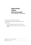
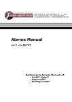
1
2001 IMPREZA SERVICE MANUAL
QUICK REFERENCE INDEX
ENGINE 1 SECTION
This service manual has been prepared
to provide SUBARU service personnel
with the necessary information and data
for the correct maintenance and repair
of SUBARU vehicles.
This manual includes the procedures
for maintenance, disassembling, reassembling, inspection and adjustment of
components and diagnostics for guidance of experienced mechanics.
Please peruse and utilize this manual
fully to ensure complete repair work for
satisfying our customers by keeping
their vehicle in optimum condition.
When replacement of parts during
repair work is needed, be sure to use
SUBARU genuine parts.
FUEL INJECTION (FUEL SYSTEMS)
FU(SOHC)
EMISSION CONTROL
(AUX. EMISSION CONTROL DEVICES)
EC(SOHC)
INTAKE (INDUCTION)
IN(SOHC)
MECHANICAL
ME(SOHC)
EXHAUST
EX(SOHC)
COOLING
CO
LUBRICATION
LU
SPEED CONTROL SYSTEMS
SP
IGNITION
IG(SOHC)
STARTING/CHARGING SYSTEMS
SC
ENGINE (DIAGNOSTICS)
EN(SOHC)
All information, illustration and specifications contained in this manual are
based on the latest product information
available at the time of publication
approval.
FUJI HEAVY INDUSTRIES LTD.
G1830GE2
COOLING
CO
1.
2.
3.
4.
5.
6.
7.
8.
9.
10.
11.
12.
13.
Page
General Description ....................................................................................2
Radiator Main Fan System..........................................................................9
Radiator Sub Fan System .........................................................................17
Engine Coolant..........................................................................................25
Water Pump ..............................................................................................27
Thermostat ................................................................................................35
Radiator.....................................................................................................37
Radiator Cap .............................................................................................45
Radiator Main Fan and Fan Motor ............................................................46
Radiator Sub Fan and Fan Motor..............................................................48
Reservoir Tank..........................................................................................50
Coolant Filler Tank ....................................................................................51
Engine Cooling System Trouble in General ..............................................52
GENERAL DESCRIPTION
COOLING
1. General Description
A: SPECIFICATIONS
Model
Non-turbo
Turbo
Electric fan + Forced engine coolant circulation sysCooling system
tem
1.6AT: Approx. 7.3
(7.71, 6.42)
1.6MT: Approx. 7.4
(7.82, 6.51)
Approx. 7.7
Total engine coolant capacity
2 (US qt, Imp qt)
2.0AT: Approx. 6.9
(8.14, 6.78)
(7.29, 6.07)
2.0MT: Approx. 7
(7.4, 6.2)
Type
Centrifugal impeller type
Discharge
20 2 (5.3 US gal, 4.4 Imp gal)/min.
Pump speed—total engine
Discharge performance I
700 rpm — 0.3 mAq (1.0 ftAq)
coolant head
Engine coolant temperature
85°C (185°F)
Discharge
100 2 (26.4 US gal, 22.0 Imp gal)/min.
Pump speed—total engine
Discharge performance II
3,000 rpm — 5.0 mAq (16.4 ftAq)
coolant head
Engine coolant temperature
85°C (185°F)
Discharge
200 2 (52.8 US gal, 44.0 Imp gal)/min.
Water pump
Pump speed—total engine
Discharge performance III
6,000 rpm — 23.0 mAq (75.5 ftAq)
coolant head
Engine coolant temperature
85°C (185°F)
Impeller diameter
76 mm (2.99 in)
Number of impeller vanes
8
Pump pulley diameter
60 mm (2.36 in)
0.5 — 0.7 mm (0.020 — 0.028 in)
Clearance between impeller Standard
and case
Limit
1.0 mm (0.039 in)
“Thrust” runout of impeller end
0.5 mm (0.020 in)
Type
Wax pellet type
Starts to open
76 — 80°C (169 — 176°F)
Thermostat
Fully opened
91°C (196°F)
Valve lift
9.0 mm (0.354 in) or more
Valve bore
35 mm (1.38 in)
Main fan
70 W
120 W
Motor
Sub fan
70 W
120 W
Radiator fan
320 mm (11.81 in) × 5 (main fan)
Fan diameter × Blade
320 mm (11.81 in) × 7 (sub fan)
Type
Down flow, pressure type
691.5 × 340 × 16 mm
691.5 × 340 × 27 mm
Core dimensions
(27.22 × 13.39 × 0.63 in) (27.22 × 13.39 × 1.06 in)
Above: 108±15 kPa
Radiator
(1.1±0.15 kg/cm2, 16±2 psi)
Pressure range in which cap valve is open
Below: −1.0 to −4.9 kPa
(−0.01 to −0.05 kg/cm2, −0.1 to −0.7 psi)
Fins
Corrugated fin type
Reservoir
Capacity
0.5 2 (0.5 US qt, 0.4 Imp qt)
tank
CO-2
GENERAL DESCRIPTION
COOLING
B: COMPONENT
1. WATER PUMP
• NON-TURBO MODEL
H2M2354A
(1)
(2)
(3)
(4)
Water pump ASSY
Gasket
Heater by-pass hose
Thermostat
(5)
(6)
Gasket
Thermostat cover
Tightening torque: N·m (kgf-m, ft-lb)
T1: First 12 (1.2, 8.7)
Second 12 (1.2, 8.7)
T2: 6.4 (0.65, 4.7)
CO-3
GENERAL DESCRIPTION
COOLING
• TURBO MODEL
H2M1785B
(1)
(2)
(3)
(4)
(5)
Thermostat case
Gasket
Thermostat
Water pump ASSY
Gasket
(6)
(7)
(8)
Header by-pass hose
Coolant filler tank by-pass hose
Water by-pass pipe
Tightening torque: N·m (kgf-m, ft-lb)
T1: First 12 (1.2, 8.7)
Second 12 (1.2, 8.7)
T2: 6.4 (0.65, 4.7)
CO-4
GENERAL DESCRIPTION
COOLING
2. RADIATOR AND RADIATOR FAN
• NON-TURBO MODEL
(8)
(6)
(5)
T5
(12)
(10)
(7)
T3
T5
(5)
T5
(4)
(15)
T1
(3)
(9)
(11)
(13)
(24)
T4
T1
(16)
T2
(17)
(2)
T4
(16)
(14)
(18)
(21)
(16)
T2
(16)
(1)
(16)
(23)
(20)
(19)
(16)
(5)
(22)
EN0068
(1)
(2)
(3)
(4)
(5)
(6)
(7)
(8)
(9)
(10)
(11)
(12)
Radiator lower cushion
Radiator
Radiator upper cushion
Radiator upper bracket
Clamp
Radiator inlet hose
Engine coolant reservoir tank cap
Over flow hose
Engine coolant reservoir tank
Sub fan shroud
Radiator sub fan
Sub fan motor
(13)
(14)
(15)
(16)
(17)
(18)
(19)
(20)
(21)
(22)
Main fan shroud
(23) Radiator lower bracket
Radiator main fan
(24) Radiator drain plug
Main fan motor
ATF hose clamp (AT vehicles only) Tightening torque: N·m (kgf-m, ft-lb)
ATF inlet hose A (AT vehicles only)
T1: 4.4 (0.45, 3.3)
ATF outlet hose A (AT vehicles
T2: 12 (1.2, 8.7)
only)
T3: 18 (1.8, 13.0)
ATF pipe (AT vehicles only)
T4: 3.4 (0.35, 2.5)
ATF inlet hose B (AT vehicles only)
T5: 4.9 (0.50, 3.6)
ATF outlet hose B (AT vehicles
only)
Radiator outlet hose
CO-5
GENERAL DESCRIPTION
COOLING
• TURBO MODEL
(21)
(20)
(19)
(5)
(5)
(6)
(5)
T5
T5
(11)
(7)
(10)
(8)
(5)
T3
T4
(13)
(16)
(4)
T1
(3)
(9)
(2)
(12)
(14)
(18)
T4
T1
(5)
T4
(15)
(17)
(1)
(5)
(23)
EN0069
(1)
(2)
(3)
(4)
(5)
(6)
(7)
(8)
(9)
Radiator lower cushion
Radiator
Radiator upper cushion
Radiator upper bracket
Clamp
Radiator inlet hose
Engine coolant reservoir tank cap
Over flow hose
Engine coolant reservoir tank
(10)
(11)
(12)
(13)
(14)
(15)
(16)
(17)
(18)
Over flow pipe
Sub fan shroud
Radiator sub fan
Radiator sub fan motor
Main fan shroud
Radiator main fan
Radiator main fan motor
Radiator outlet hose
Radiator drain plug
CO-6
(19)
(20)
(21)
Engine coolant filler tank
Engine coolant filler tank cap
Engine coolant hose
Tightening torque: N·m (kgf-m, ft-lb)
T1: 4.4 (0.45, 3.3)
T2: 18 (1.8, 13.0)
T3: 3.4 (0.35, 2.5)
T4: 4.9 (0.50, 3.6)
GENERAL DESCRIPTION
COOLING
C: CAUTION
• Wear working clothing, including a cap, protective goggles, and protective shoes during operation.
• Remove contamination including dirt and corrosion before removal, installation or disassembly.
• Keep the disassembled parts in order and protect them from dust or dirt.
• Before removal, installation or disassembly, be
sure to clarify the failure. Avoid unnecessary removal, installation, disassembly, and replacement.
• Be careful not to burn your hands, because each
part in the vehicle is hot after running.
• Be sure to tighten fasteners including bolts and
nuts to the specified torque.
• Place shop jacks or safety stands at the specified
points.
• Before disconnecting electrical connectors of
sensors or units, be sure to disconnect negative
terminal from battery.
CO-7
GENERAL DESCRIPTION
COOLING
D: PREPARATION TOOL
ILLUSTRATION
TOOL NUMBER
499977300
DESCRIPTION
CRANK PULLEY
WRENCH
REMARKS
Used for stopping crankshaft pulley when
loosening and tightening crankshaft pulley
bolts.
499207100
CAMSHAFT
SPROCKET
WRENCH
Used for removing and installing camshaft
sprocket. (Non-turbo LH side only)
499207400
CAMSHAFT
SPROCKET
WRENCH
Used for removing and installing camshaft
sprocket.
B2M4157
B2M3859
B2M4158
CO-8
RADIATOR MAIN FAN SYSTEM
COOLING
2. Radiator Main Fan System
A: SCHEMATIC
1. NON-TURBO MODEL
BATTERY
SBF-1
No.3
B72
IGNITION
SWITCH
SBF-4
No.17
No.18
AIR CONDITIONING
RELAY HOLDER
AIR CONDITIONING
RELAY HOLDER
1
3
2
4
26
28
27
25
18
20
19
17
F27 20A
MAIN
F66 FAN
RELAY
F27 20A
MAIN FAN
MOTOR
SUB
F29 FAN
RELAY
SUB FAN
MOTOR
F45
2
1
1
2
2
1
B62
F17
F16
1 LHD :2
RHD :7
2 LHD :12
3
12
RHD :17
B134 ECM
F16
LHD:
RHD:
F45
F45
F17
1 2 3 4 5
6 7 8 9 10 11
12 13 14 15 16 17 18 19 20 21 22 23 24
2 1
B134
1 2
3 4
5 6
7 8
9 10 11 12 13 14 15 16 17 18 19 20 21 22 23
24 25
26 27 28 29
30 31 32 33
34 35
1 2 3 4
10 11 12 13 14
F31
F27
F28
1
2
3
4
F30
F29
5 6 7 8 9
15 16 17 18 19 20
F67
F66
5 6 9 13 14 17 21 22 25
15
18
26
7
10
23
8 11 12 16 19 20 24 27 28
29
30
CO-9
EN0880
RADIATOR MAIN FAN SYSTEM
COOLING
2. TURBO MODEL
BATTERY
SBF-1
B72
IGNITION
SWITCH
No.18
SBF-4
17
28
LHD : 2
RHD : 7
*2
LHD : 12
RHD : 17
* 12
*
F29
F28
1
3
2
1
3
2
F16
E
B72
1 2
3 4
(BLUE)
F27
2
3
4
M
SUB FAN
MOTOR
F28
1
F17
M
E
F29
4
3
MAIN FAN MAIN FAN
RELAY1
RELAY2
30A
SUB FAN
RELAY1
2
1
SUB FAN
RELAY2
30A
25
27
28
26
24
22
21
23
F45
8
6
5
7
B62
17
19
20
18
B137 ECM
No.17
*1
MAIN FAN
MOTOR
F30
5 6 9 13 14 17 21 22 25
7
10
15
18
23
26
8 11 12 16 19 20 24 27 28
F66
29
30
F30
F66
F27
AIR CONDITIONING RELAY HOLDER
B137
F45
F16
1 2
3 4 5 6 7 8 9
10 11 12 13 14 15 16 17 18 19 20 21
22 23 24 25 26
27 28
29 30 31
6 7 8 9 10 11
1 2 3 4 5
12 13 14 15 16 17 18 19 20 21 22 23 24
(LHD)
F17
3 2 1
1 2 3 4
5 6 7 8
9 10 11 12 13 14 15 16 17 18
(RHD)
EN0260
CO-10
RADIATOR MAIN FAN SYSTEM
COOLING
B: INSPECTION
1. NON-TURBO MODEL
DETECTING CONDITION:
Condition:
• Engine coolant temperature is above 95°C
(203°F).
1
2
3
4
5
6
7
• Vehicle speed is below 19 km/h (12 MPH).
TROUBLE SYMPTOM:
• Radiator main fan does not rotate under the
above conditions.
Step
Check
Yes
CHECK POWER SUPPLY TO MAIN FAN MO- Is the voltage more than 10 V? Go to step 2.
TOR.
CAUTION:
Be careful not to overheat engine during repair.
1)Turn ignition switch to OFF.
2)Disconnect connector from main fan motor.
3)Start the engine, and warm it up until engine
coolant temperature increases over 95°C
(203°F).
4)Stop the engine and turn ignition switch to
ON.
5)Measure voltage between main fan motor
connector and chassis ground.
Connector & terminal
(F17) No. 2 (+) — Chassis ground (−):
CHECK GROUND CIRCUIT OF MAIN FAN
MOTOR.
1)Turn ignition switch to OFF.
2)Measure resistance between main fan motor
connector and chassis ground.
Connector & terminal
(F17) No. 1 — Chassis ground:
CHECK POOR CONTACT.
Check poor contact in main fan motor connector.
CHECK MAIN FAN MOTOR.
Connect battery positive (+) terminal to terminal No. 2, and negative (−) terminal to terminal
No. 1 of main fan motor connector.
CHECK POWER SUPPLY TO MAIN FAN RELAY.
1)Turn ignition switch to OFF.
2)Remove main fan relay from A/C relay
holder.
3)Measure voltage between main fan relay terminal and chassis ground.
Connector & terminal
(F66) No. 26 (+) — Chassis ground (−):
CHECK POWER SUPPLY TO MAIN FAN RELAY.
1)Turn ignition switch to ON.
2)Measure voltage between main fan relay terminal and chassis ground.
Connector & terminal
(F66) No. 28 (+) — Chassis ground (−):
CHECK 20 A FUSE.
1)Remove 20 A fuse from A/C relay holder.
2)Check condition of fuse.
No
Go to step 5.
Is the resistance less than 5
Ω?
Go to step 3.
Repair open circuit
in harness
between main fan
motor connector
and chassis
ground.
Is there poor contact in main
fan motor connector?
Repair poor contact in main fan
motor connector.
Repair poor contact in main fan
motor connector.
Go to step 4.
Does the main fan rotate?
Replace main fan
motor with a new
one.
Is the voltage more than 10 V? Go to step 6.
Go to step 7.
Is the voltage more than 10 V? Go to step 10.
Go to step 9.
Is the fuse blown-out?
Go to step 8.
CO-11
Replace fuse.
RADIATOR MAIN FAN SYSTEM
COOLING
8
9
10
11
12
13
14
Step
Check
Is the voltage more than 10 V?
CHECK POWER SUPPLY TO A/C RELAY
HOLDER 20 A FUSE TERMINAL.
Measure voltage of harness between A/C relay
holder 20 A fuse terminal and chassis ground.
Connector & terminal
(F27) No. 1 (+) — Chassis ground (−):
Is the fuse blown-out?
CHECK FUSE.
1)Turn ignition switch to OFF.
2)Remove fuse No. 18 from joint box.
3)Check condition of fuse.
CHECK MAIN FAN RELAY.
1)Turn ignition switch to OFF.
2)Remove main fan relay.
3)Measure resistance of main fan relay.
Terminal
No. 26 — No. 25:
CHECK MAIN FAN RELAY.
1)Connect battery to terminals No. 27 and No.
28 of main fan relay.
2)Measure resistance of main fan relay.
Terminal
No. 26 — No. 25:
CHECK HARNESS BETWEEN MAIN FAN
RELAY TERMINAL AND MAIN FAN MOTOR
CONNECTOR.
Measure resistance of harness between main
fan motor connector and main fan relay terminal.
Connector & terminal
(F17) No. 2 — (F66) No. 25:
CHECK HARNESS BETWEEN MAIN FAN
RELAY AND ECM.
1)Turn ignition switch to OFF.
2)Disconnect connector from ECM.
3)Measure resistance of harness between
main fan relay connector and ECM connector.
Connector & terminal
(F66) No. 27 — (B134) No. 3:
CHECK POOR CONTACT.
Check poor contact in connector between main
fan and ECM.
Yes
Repair open circuit
in harness
between 20 A fuse
and main fan relay
terminal.
No
Repair open circuit
in harness
between main fuse
box connector and
20 A fuse terminal.
Replace fuse.
Repair open circuit
in harness
between main fan
relay and ignition
switch.
Replace main fan
relay.
Is the resistance more than 1
MΩ?
Go to step 11.
Is the resistance less than 1
Ω?
Go to step 12.
Replace main fan
relay.
Is the resistance less than 1
Ω?
Go to step 13.
Repair open circuit
in harness
between main fan
motor connector
and main fan relay
terminal.
Is the resistance less than 1
Ω?
Go to step 14.
Repair open circuit
in harness
between main fan
relay and ECM.
Is there poor contact in conRepair poor connector between main fan motor tact connector.
and ECM?
NOTE:
Inspection by your Subaru distributor is required,
because probable cause is deterioration of multiple
parts.
CO-12
Contact with your
Subaru distributor.
RADIATOR MAIN FAN SYSTEM
COOLING
2. TURBO MODEL
DETECTING CONDITION:
Condition:
• Engine coolant temperature is above 96°C
(205°F).
• A/C compressor is rotated.
• Vehicle speed is below 19 km/h (12 MPH).
1
2
3
4
5
6
7
Step
CHECK OPERATION OF RADIATOR.
1)Run the engine at idle. (Vehicle stationary)
2)Turn the A/C switch to OFF.
3)Warm the engine coolant temperature over
96°C (205°F).
CHECK OPERATION OF RADIATOR.
1)Turn the A/C switch ON at condition of step
1.
CHECK POWER SUPPLY TO MAIN FAN MOTOR.
CAUTION:
Be careful not to overheat engine during repair.
1)Turn ignition switch to OFF.
2)Disconnect connector from main fan motor.
3)Start the engine, and warm it up until engine
coolant temperature increases over 96°C
(205°F).
4)Stop the engine and turn ignition switch to
ON.
5)Measure voltage between main fan motor
connector and chassis ground.
Connector & terminal
(F17) No. 3 (+) — Chassis ground (−):
CHECK GROUND CIRCUIT OF MAIN FAN
MOTOR.
1)Turn ignition switch to OFF.
2)Measure resistance between main fan motor
connector and chassis ground.
Connector & terminal
(F17) No. 1 — Chassis ground:
CHECK POOR CONTACT.
Check poor contact in main fan motor connector.
CHECK MAIN FAN MOTOR.
Connect battery positive (+) terminal to terminal No. 3, and negative (−) terminal to terminal
No. 1 of main fan motor connector.
CHECK POWER SUPPLY TO MAIN FAN
RELAY1.
1)Turn ignition switch to OFF.
2)Remove main fan relay1 from A/C relay
holder.
3)Measure voltage between main fan relay1
terminal and chassis ground.
Connector & terminal
(F66) No. 26 (+) — Chassis ground (−):
TROUBLE SYMPTOM:
• Radiator main fan does not rotate under the
above conditions.
• Radiator main fan does not rotate at high speed
when the following conditions are both met:
(1) Engine coolant temperature is above 90°C
(194°F)
(2) A/C is ON
Check
Does the main radiator fan
rotate?
Yes
Go to step 2.
No
Go to step 3.
Does the main radiator fan
Radiator main fan Go to step 17.
rotate faster when A/C comsystem is okay.
pressor is operated?
Is the voltage more than 10 V? Go to step 4.
Go to step 7.
Is the resistance less than 5
Ω?
Go to step 5.
Repair open circuit
in harness
between main fan
motor connector
and chassis
ground.
Is there poor contact in main
fan motor connector?
Repair poor contact in main fan
motor connector.
Repair poor contact in main fan
motor connector.
Go to step 6.
Does the main fan rotate?
Is the voltage more than 10 V? Go to step 8.
CO-13
Replace main fan
motor with a new
one.
Go to step 9.
RADIATOR MAIN FAN SYSTEM
COOLING
8
9
10
11
12
13
14
15
16
Step
CHECK POWER SUPPLY TO MAIN FAN
RELAY1.
1)Turn ignition switch to ON.
2)Measure voltage between main fan relay1
terminal and chassis ground.
Connector & terminal
(F66) No. 27 (+) — Chassis ground (−):
CHECK 30 A FUSE.
1)Remove 30 A fuse from A/C relay holder.
2)Check condition of fuse.
CHECK POWER SUPPLY TO A/C RELAY
HOLDER 30 A FUSE TERMINAL.
Measure voltage of harness between A/C relay
holder 30 A fuse terminal and chassis ground.
Connector & terminal
(F27) No. 1 (+) — Chassis ground (−):
CHECK FUSE.
1)Turn ignition switch to OFF.
2)Remove fuse No. 18 from joint box.
3)Check condition of fuse.
Check
Yes
Is the voltage more than 10 V? Go to step 12.
No
Go to step 11.
Is the fuse blown-out?
Go to step 10.
CHECK MAIN FAN RELAY.
1)Turn ignition switch to OFF.
2)Remove main fan relay1.
3)Measure resistance of main fan relay1.
Terminal
No. 26 — No. 25:
CHECK MAIN FAN RELAY.
1)Connect battery to terminals No. 27 and No.
28 of main fan relay1.
2)Measure resistance of main fan relay1.
Terminal
No. 26 — No. 25:
CHECK HARNESS BETWEEN MAIN FAN
RELAY TERMINAL AND MAIN FAN MOTOR
CONNECTOR.
Measure resistance of harness between main
fan motor connector and main fan relay terminal.
Connector & terminal
(F17) No. 3 — (F66) No. 25:
CHECK HARNESS BETWEEN MAIN FAN
RELAY AND ECM.
1)Turn ignition switch to OFF.
2)Disconnect connector from ECM.
3)Measure resistance of harness between
main fan relay connector and ECM connector.
Connector & terminal
(F66) No. 28 — (B137) No. 17:
CHECK POOR CONTACT.
Check poor contact in connector between main
fan and ECM.
Replace fuse.
Is the voltage more than 10 V? Repair open circuit
in harness
between 30 A fuse
and main fan relay
terminal.
Repair open circuit
in harness
between main fuse
box connector and
30 A fuse terminal.
Is the fuse blown-out?
Replace fuse.
Is the resistance more than 1
MΩ?
Go to step 13.
Repair open circuit
in harness
between main fan
relay and ignition
switch.
Replace main fan
relay.
Is the resistance less than 1
Ω?
Go to step 14.
Replace main fan
relay.
Is the resistance less than 1
Ω?
Go to step 15.
Repair open circuit
in harness
between main fan
motor connector
and main fan relay
terminal.
Is the resistance less than 1
Ω?
Go to step 16.
Repair open circuit
in harness
between main fan
relay and ECM.
Is there poor contact in conRepair poor connector between main fan motor tact connector.
and ECM?
CO-14
Contact with your
Subaru distributor.
RADIATOR MAIN FAN SYSTEM
COOLING
17
18
19
20
21
22
23
24
Step
Check
Yes
CHECK POWER SUPPLY TO MAIN FAN MO- Is the voltage more than 10 V? Go to step 18.
TOR.
CAUTION:
Be careful not to overheat engine during repair.
1)Turn ignition switch to OFF.
2)Disconnect connector from main fan motor.
3)Start the engine, and warm it up until engine
coolant temperature increases over 96°C
(205°F).
4)Turn the A/C switch ON.
5)Measure voltage while A/C compressor is
rotating.
6)Measure voltage between main fan motor
connector and chassis ground.
Connector & terminal
(F17) No. 2 (+) — Chassis ground (−):
CHECK POOR CONTACT.
Check poor contact in main fan motor connector.
CHECK MAIN FAN MOTOR.
Connect battery positive (+) terminal to terminal No. 2, and negative (−) terminal to terminal
No. 1 of main fan motor connector.
CHECK POWER SUPPLY TO MAIN FAN
RELAY2.
1)Turn ignition switch to OFF.
2)Remove main fan relay2 from A/C relay
holder.
3)Measure voltage between main fan relay2
terminal and chassis ground.
Connector & terminal
(F30) No. 23 (+) — Chassis ground (−):
CHECK POWER SUPPLY TO MAIN FAN
RELAY2.
1)Turn ignition switch to ON.
2)Measure voltage between main fan relay2
terminal and chassis ground.
Connector & terminal
(F30) No. 22 (+) — Chassis ground (−):
CHECK 30 A FUSE.
1)Remove 30 A fuse from A/C relay holder.
2)Check condition of fuse.
CHECK POWER SUPPLY TO A/C RELAY
HOLDER 30 A FUSE TERMINAL.
Measure voltage of harness between A/C relay
holder 30 A fuse terminal and chassis ground.
Connector & terminal
(F27) No. 1 (+) — Chassis ground (−):
CHECK FUSE.
1)Turn ignition switch to OFF.
2)Remove fuse No. 18 from joint box.
3)Check condition of fuse.
Is there poor contact in main
fan motor connector?
Does the main fan rotate?
Repair poor contact in main fan
motor connector.
Repair poor contact in main fan
motor connector.
No
Go to step 20.
Go to step 19.
Replace main fan
motor with a new
one.
Is the voltage more than 10 V? Go to step 21.
Go to step 22.
Is the voltage more than 10 V? Go to step 25.
Go to step 24.
Is the fuse blown-out?
Go to step 23.
Replace fuse.
Is the voltage more than 10 V? Repair open circuit
in harness
between 30 A fuse
and main fan relay
terminal.
Repair open circuit
in harness
between main fuse
box connector and
30 A fuse terminal.
Is the fuse blown-out?
Repair open circuit
in harness
between main fan
relay and ignition
switch.
CO-15
Replace fuse.
RADIATOR MAIN FAN SYSTEM
COOLING
25
26
27
28
29
Step
CHECK MAIN FAN RELAY.
1)Turn ignition switch to OFF.
2)Remove main fan relay2.
3)Measure resistance of main fan relay2.
Terminal
No. 23 — No. 24:
CHECK MAIN FAN RELAY.
1)Connect battery to terminals No. 21 and No.
22 of main fan relay1.
2)Measure resistance of main fan relay2.
Terminal
No. 23 — No. 24:
CHECK HARNESS BETWEEN MAIN FAN
RELAY TERMINAL AND MAIN FAN MOTOR
CONNECTOR.
Measure resistance of harness between main
fan motor connector and main fan relay terminal.
Connector & terminal
(F17) No. 2 — (F66) No. 24:
CHECK HARNESS BETWEEN MAIN FAN
RELAY AND ECM.
1)Turn ignition switch to OFF.
2)Disconnect connector from ECM.
3)Measure resistance of harness between
main fan relay connector and ECM connector.
Connector & terminal
(F30) No. 21 — (B134) No. 28:
CHECK POOR CONTACT.
Check poor contact in connector between main
fan and ECM.
Check
Is the resistance more than 1
MΩ?
Yes
Go to step 26.
No
Replace main fan
relay.
Is the resistance less than 1
Ω?
Go to step 27.
Replace main fan
relay.
Is the resistance less than 1
Ω?
Go to step 28.
Repair open circuit
in harness
between main fan
motor connector
and main fan relay
terminal.
Is the resistance less than 1
Ω?
Go to step 29.
Repair open circuit
in harness
between main fan
relay and ECM.
Repair poor conIs there poor contact in connector between main fan motor tact connector.
and ECM?
NOTE:
Inspection by your Subaru distributor is required,
because probable cause is deterioration of multiple
parts.
CO-16
Contact with your
Subaru distributor.
RADIATOR SUB FAN SYSTEM
COOLING
3. Radiator Sub Fan System
A: SCHEMATIC
1. NON-TURBO MODEL
BATTERY
SBF-1
No.3
B72
IGNITION
SWITCH
SBF-4
No.17
No.18
AIR CONDITIONING
RELAY HOLDER
AIR CONDITIONING
RELAY HOLDER
1
3
2
4
26
28
27
25
18
20
19
17
F27 20A
MAIN
F66 FAN
RELAY
F27 20A
MAIN FAN
MOTOR
SUB
F29 FAN
RELAY
SUB FAN
MOTOR
F45
2
1
1
2
2
1
B62
F17
F16
1 LHD :2
RHD :7
2 LHD :12
3
12
RHD :17
B134 ECM
F16
LHD:
RHD:
F45
F45
F17
1 2 3 4 5
6 7 8 9 10 11
12 13 14 15 16 17 18 19 20 21 22 23 24
2 1
B134
1 2
3 4
5 6
7 8
9 10 11 12 13 14 15 16 17 18 19 20 21 22 23
24 25
26 27 28 29
30 31 32 33
34 35
1 2 3 4
10 11 12 13 14
F31
F27
F28
1
2
3
4
F30
F29
5 6 7 8 9
15 16 17 18 19 20
F67
F66
5 6 9 13 14 17 21 22 25
15
18
26
7
10
23
8 11 12 16 19 20 24 27 28
29
30
CO-17
EN0880
RADIATOR SUB FAN SYSTEM
COOLING
2. TURBO MODEL
BATTERY
SBF-1
B72
IGNITION
SWITCH
No.18
SBF-4
17
28
LHD : 2
RHD : 7
*2
LHD : 12
RHD : 17
* 12
*
F29
F28
1
3
2
1
3
2
F16
E
B72
1 2
3 4
(BLUE)
F27
2
3
4
M
SUB FAN
MOTOR
F28
1
F17
M
E
F29
4
3
MAIN FAN MAIN FAN
RELAY1
RELAY2
30A
SUB FAN
RELAY1
2
1
SUB FAN
RELAY2
30A
25
27
28
26
24
22
21
23
F45
8
6
5
7
B62
17
19
20
18
B137 ECM
No.17
*1
MAIN FAN
MOTOR
F30
5 6 9 13 14 17 21 22 25
7
10
15
18
23
26
8 11 12 16 19 20 24 27 28
F66
29
30
F30
F66
F27
AIR CONDITIONING RELAY HOLDER
B137
F45
F16
1 2
3 4 5 6 7 8 9
10 11 12 13 14 15 16 17 18 19 20 21
22 23 24 25 26
27 28
29 30 31
6 7 8 9 10 11
1 2 3 4 5
12 13 14 15 16 17 18 19 20 21 22 23 24
(LHD)
F17
3 2 1
1 2 3 4
5 6 7 8
9 10 11 12 13 14 15 16 17 18
(RHD)
EN0260
CO-18
RADIATOR SUB FAN SYSTEM
COOLING
B: INSPECTION
1. NON-TURBO MODEL
NOTE:
System for A/C equipped vehicles only.
DETECTING CONDITION:
Condition (1):
• Engine coolant temperature is below 95°C
(203°F).
1
2
3
4
5
6
• A/C switch is turned ON.
• Vehicle speed is below 19 km/h (12 MPH).
Condition (2):
• Engine coolant temperature is above 100°C
(212°F).
• A/C switch is turned OFF.
• Vehicle speed is below 19 km/h (12 MPH).
TROUBLE SYMPTOM:
• Radiator sub fan does not rotate under conditions (1) and (2) above.
Step
Check
Yes
CHECK POWER SUPPLY TO SUB FAN MO- Is the voltage more than 10 V? Go to step 2.
TOR.
CAUTION:
Be careful not to overheat engine during repair.
1)Turn ignition switch to OFF.
2)Disconnect connector from sub fan motor
and main fan motor.
3)Start the engine, and warm it up until engine
coolant temperature increases over 100°C
(212°F).
4)Stop the engine and turn ignition switch to
ON.
5)Measure voltage between sub fan motor
connector and chassis ground.
Connector & terminal
(F16) No. 2 (+) — Chassis ground (−):
CHECK GROUND CIRCUIT OF SUB FAN
MOTOR.
1)Turn ignition switch to OFF.
2)Measure resistance between sub fan motor
connector and chassis ground.
Connector & terminal
(F16) No. 1 — Chassis ground:
CHECK POOR CONTACT.
Check poor contact in sub fan motor connector.
CHECK SUB FAN MOTOR.
Connect battery positive (+) terminal to terminal No. 2, and negative (−) terminal to terminal
No. 1 of sub fan motor connector.
CHECK POWER SUPPLY TO SUB FAN RELAY.
1)Turn ignition switch to OFF.
2)Remove sub fan relay from A/C relay holder.
3)Measure voltage between sub fan relay terminal and chassis ground.
Connector & terminal
(F28) No. 18 (+) — Chassis ground (−):
CHECK POWER SUPPLY TO SUB FAN RELAY.
1)Turn ignition switch to ON.
2)Measure voltage between sub fan relay terminal and chassis ground.
Connector & terminal
(F28) No. 20 (+) — Chassis ground (−):
Is the resistance less than 5
Ω?
Go to step 3.
No
Go to step 5.
Repair open circuit
in harness
between sub fan
motor connector
and chassis
ground.
Is there poor contact in sub fan Repair poor conmotor connector?
tact in sub fan
motor connector.
Does the sub fan rotate?
Repair poor contact in sub fan
motor connector.
Replace sub fan
motor with a new
one.
Is the voltage more than 10 V? Go to step 6.
Go to step 7.
Is the voltage more than 10 V? Go to step 10.
Go to step 9.
CO-19
Go to step 4.
RADIATOR SUB FAN SYSTEM
COOLING
7
8
9
10
11
12
13
14
Step
Check
Is the fuse blown-out?
CHECK 20 A FUSE.
1)Remove 20 A fuse from A/C relay holder.
2)Check condition of fuse.
Is the voltage more than 10 V?
CHECK POWER SUPPLY TO A/C RELAY
HOLDER 20 A FUSE TERMINAL.
Measure voltage of harness between A/C relay
holder 20 A fuse terminal and chassis ground.
Connector & terminal
(F27) No. 3 (+) — Chassis ground (−):
Is the fuse blown-out?
CHECK FUSE.
1)Turn ignition switch to OFF.
2)Remove fuse No. 17 from joint box.
3)Check condition of fuse.
CHECK SUB FAN RELAY.
1)Turn ignition switch to OFF.
2)Measure resistance of sub fan relay.
Terminal
No. 17 — No. 18:
CHECK SUB FAN RELAY.
1)Connect battery to terminals No. 20 and No.
19 of sub fan relay.
2)Measure resistance of sub fan relay.
Terminal
No. 17 — No. 18:
CHECK HARNESS BETWEEN SUB FAN RELAY TERMINAL AND SUB FAN MOTOR
CONNECTOR.
Measure resistance of harness between sub
fan motor connector and sub fan relay terminal.
Connector & terminal
(F16) No. 2 — (F28) No. 17:
CHECK HARNESS BETWEEN SUB FAN RELAY AND ECM.
1)Turn ignition switch to OFF.
2)Disconnect connector from ECM.
3)Measure resistance of harness between sub
fan relay connector and ECM connector.
Connector & terminal
(F28) No. 19 — (B134) No. 12:
CHECK POOR CONTACT.
Check poor contact in connnector between sub
fan and ECM.
Yes
Replace fuse.
No
Go to step 8.
Repair open circuit
in harness
between 20 A fuse
and sub fan relay
terminal.
Repair open circuit
in harness
between main fuse
box connector and
20 A fuse terminal.
Replace fuse.
Repair open circuit
in harness
between sub fan
relay and ignition
switch.
Replace sub fan
relay.
Is the resistance more than 1
MΩ?
Go to step 11.
Is the resistance less than 1
Ω?
Go to step 12.
Replace sub fan
relay.
Is the resistance less than 1
Ω?
Go to step 13.
Repair open circuit
in harness
between sub fan
motor and sub fan
relay connector.
Is the resistance less than 1
Ω?
Go to step 14.
Repair open circuit
in harness
between sub fan
relay and ECM.
Is there poor contact in connector between sub fan motor
and ECM?
Repair poor contact connector.
Contact with your
Subaru distributor.
NOTE:
Inspection by your Subaru distributor is required,
because probable cause is deterioration of multiple
parts.
CO-20
RADIATOR SUB FAN SYSTEM
COOLING
2. TURBO MODEL
DETECTING CONDITION:
Condition:
• Engine coolant temperature is above 96°C
(205°F).
• A/C compressor is rotated.
• Vehicle speed is below 19 km/h (12 MPH).
1
2
3
4
5
6
7
Step
CHECK OPERATION OF RADIATOR.
1)Run the engine at idle. (Vehicle stationary)
2)Turn the A/C switch to OFF.
3)Warm the engine coolant temperature over
96°C (205°F).
CHECK OPERATION OF RADIATOR.
1)Turn the A/C switch ON at condition of step
1.
CHECK POWER SUPPLY TO SUB FAN MOTOR.
CAUTION:
Be careful not to overheat engine during repair.
1)Turn ignition switch to OFF.
2)Disconnect connector from sub fan motor.
3)Start the engine, and warm it up until engine
coolant temperature increases over 96°C
(205°F).
4)Stop the engine and turn ignition switch to
ON.
5)Measure voltage between sub fan motor
connector and chassis ground.
Connector & terminal
(F16) No. 3 (+) — Chassis ground (−):
CHECK GROUND CIRCUIT OF SUB FAN
MOTOR.
1)Turn ignition switch to OFF.
2)Measure resistance between sub fan motor
connector and chassis ground.
Connector & terminal
(F16) No. 1 — Chassis ground:
CHECK POOR CONTACT.
Check poor contact in sub fan motor connector.
CHECK MAIN FAN MOTOR.
Connect battery positive (+) terminal to terminal No. 3, and negative (−) terminal to terminal
No. 1 of sub fan motor connector.
CHECK POWER SUPPLY TO SUB FAN
RELAY1.
1)Turn ignition switch to OFF.
2)Remove sub fan relay1 from A/C relay
holder.
3)Measure voltage between sub fan relay1 terminal and chassis ground.
Connector & terminal
(F28) No. 7 (+) — Chassis ground (−):
TROUBLE SYMPTOM:
• Radiator sub fan does not rotate under the above
conditions.
• Radiator sub fan does not rotate at high speed
when the following conditions are both met:
(1) Engine coolant temperature is above 90°C
(194°F)
(2) A/C is ON
Check
Does the radiator sub fan
rotate?
Yes
Go to step 2.
No
Go to step 3.
Does the radiator sub fan
Radiator main fan Go to step 17.
rotate faster when A/C comsystem is okay.
pressor is operated?
Is the voltage more than 10 V? Go to step 4.
Go to step 7.
Is the resistance less than 5
Ω?
Go to step 5.
Repair open circuit
in harness
between sub fan
motor connector
and chassis
ground.
Is there poor contact in sub fan Repair poor conmotor connector?
tact in sub fan
motor connector.
Does the main fan rotate?
Repair poor contact in sub fan
motor connector.
Replace sub fan
motor with a new
one.
Is the voltage more than 10 V? Go to step 8.
Go to step 9.
CO-21
Go to step 6.
RADIATOR SUB FAN SYSTEM
COOLING
8
9
10
11
12
13
14
15
16
Step
CHECK POWER SUPPLY TO SUB FAN
RELAY1.
1)Turn ignition switch to ON.
2)Measure voltage between sub fan relay1 terminal and chassis ground.
Connector & terminal
(F28) No. 5 (+) — Chassis ground (−):
CHECK 30 A FUSE.
1)Remove 30 A fuse from A/C relay holder.
2)Check condition of fuse.
CHECK POWER SUPPLY TO A/C RELAY
HOLDER 30 A FUSE TERMINAL.
Measure voltage of harness between A/C relay
holder 30 A fuse terminal and chassis ground.
Connector & terminal
(F27) No. 3 (+) — Chassis ground (−):
CHECK FUSE.
1)Turn ignition switch to OFF.
2)Remove fuse No. 17 from joint box.
3)Check condition of fuse.
Check
Yes
Is the voltage more than 10 V? Go to step 12.
No
Go to step 11.
Is the fuse blown-out?
Go to step 10.
CHECK SUB FAN RELAY.
1)Turn ignition switch to OFF.
2)Remove main fan relay1.
3)Measure resistance of sub fan relay1.
Terminal
No. 7 — No. 8:
CHECK SUB FAN RELAY.
1)Connect battery to terminals No. 6 and No. 5
of sub fan relay1.
2)Measure resistance of sub fan relay.
Terminal
No. 7 — No. 8:
CHECK HARNESS BETWEEN SUB FAN RELAY TERMINAL AND SUB FAN MOTOR
CONNECTOR.
Measure resistance of harness between sub
fan motor connector and sub fan relay terminal.
Connector & terminal
(F16) No. 3 — (F28) No. 8:
CHECK HARNESS BETWEEN SUB FAN RELAY AND ECM.
1)Turn ignition switch to OFF.
2)Disconnect connector from ECM.
3)Measure resistance of harness between sub
fan relay connector and ECM connector.
Connector & terminal
(F28) No. 6 — (B137) No. 17:
CHECK POOR CONTACT.
Check poor contact in connector between sub
fan and ECM.
Replace fuse.
Is the voltage more than 10 V? Repair open circuit
in harness
between 30 A fuse
and sub fan relay
terminal.
Repair open circuit
in harness
between sub fuse
box connector and
30 A fuse terminal.
Is the fuse blown-out?
Replace fuse.
Is the resistance more than 1
MΩ?
Go to step 13.
Repair open circuit
in harness
between sub fan
relay and ignition
switch.
Replace sub fan
relay.
Is the resistance less than 1
Ω?
Go to step 14.
Replace sub fan
relay.
Is the resistance less than 1
Ω?
Go to step 15.
Repair open circuit
in harness
between sub fan
motor connector
and sub fan relay
terminal.
Is the resistance less than 1
Ω?
Go to step 16.
Repair open circuit
in harness
between sub fan
relay and ECM.
Is there poor contact in connector between sub fan motor
and ECM?
Repair poor contact connector.
Contact with your
Subaru distributor.
CO-22
RADIATOR SUB FAN SYSTEM
COOLING
17
18
19
20
21
22
23
24
Step
Check
Yes
CHECK POWER SUPPLY TO SUB FAN MO- Is the voltage more than 10 V? Go to step 18.
TOR.
CAUTION:
Be careful not to overheat engine during repair.
1)Turn ignition switch to OFF.
2)Disconnect connector from sub fan motor.
3)Start the engine, and warm it up until engine
coolant temperature increases over 96°C
(205°F).
4)Turn the A/C switch ON.
5)Measure voltage while A/C compressor is
rotating.
6)Measure voltage between sub fan motor
connector and chassis ground.
Connector & terminal
(F16) No. 2 (+) — Chassis ground (−):
CHECK POOR CONTACT.
Check poor contact in sub fan motor connector.
CHECK SUB FAN MOTOR.
Connect battery positive (+) terminal to terminal No. 2, and negative (−) terminal to terminal
No. 1 of sub fan motor connector.
CHECK POWER SUPPLY TO SUB FAN
RELAY2.
1)Turn ignition switch to OFF.
2)Remove sub fan relay2 from A/C relay
holder.
3)Measure voltage between sub fan relay2 terminal and chassis ground.
Connector & terminal
(F29) No. 18 (+) — Chassis ground (−):
CHECK POWER SUPPLY TO SUB FAN
RELAY2.
1)Turn ignition switch to ON.
2)Measure voltage between sub fan relay2 terminal and chassis ground.
Connector & terminal
(F29) No. 20 (+) — Chassis ground (−):
CHECK 30 A FUSE.
1)Remove 30 A fuse from A/C relay holder.
2)Check condition of fuse.
CHECK POWER SUPPLY TO A/C RELAY
HOLDER 30 A FUSE TERMINAL.
Measure voltage of harness between A/C relay
holder 30 A fuse terminal and chassis ground.
Connector & terminal
(F27) No. 3 (+) — Chassis ground (−):
CHECK FUSE.
1)Turn ignition switch to OFF.
2)Remove fuse No. 17 from joint box.
3)Check condition of fuse.
No
Go to step 20.
Is there poor contact in sub fan Repair poor conmotor connector?
tact in sub fan
motor connector.
Does the main fan rotate?
Repair poor contact in sub fan
motor connector.
Replace sub fan
motor with a new
one.
Is the voltage more than 10 V? Go to step 21.
Go to step 22.
Is the voltage more than 10 V? Go to step 23.
Go to step 24.
Is the fuse blown-out?
Go to step 23.
Replace fuse.
Go to step 19.
Is the voltage more than 10 V? Repair open circuit
in harness
between 30 A fuse
and sub fan relay
terminal.
Repair open circuit
in harness
between sub fuse
box connector and
30 A fuse terminal.
Is the fuse blown-out?
Repair open circuit
in harness
between sub fan
relay and ignition
switch.
CO-23
Replace fuse.
RADIATOR SUB FAN SYSTEM
COOLING
25
26
27
28
29
Step
CHECK SUB FAN RELAY.
1)Turn ignition switch to OFF.
2)Remove sub fan relay2.
3)Measure resistance of main fan relay2.
Terminal
No. 18 — No. 17:
CHECK MAIN FAN RELAY.
1)Connect battery to terminals No. 19 and No.
20 of sub fan relay2.
2)Measure resistance of main fan relay2.
Terminal
No. 18 — No. 17:
CHECK HARNESS BETWEEN SUB FAN RELAY TERMINAL AND SUB FAN MOTOR
CONNECTOR.
Measure resistance of harness between sub
fan motor connector and sub fan relay2 terminal.
Connector & terminal
(F16) No. 2 — (F29) No. 17:
CHECK HARNESS BETWEEN SUB FAN RELAY AND ECM.
1)Turn ignition switch to OFF.
2)Disconnect connector from ECM.
3)Measure resistance of harness between sub
fan relay connector and ECM connector.
Connector & terminal
(F29) No. 19 — (B137) No. 28:
CHECK POOR CONTACT.
Check poor contact in connector between sub
fan and ECM.
Check
Is the resistance more than 1
MΩ?
Yes
Go to step 26.
No
Replace sub fan
relay.
Is the resistance less than 1
Ω?
Go to step 27.
Replace sub fan
relay.
Is the resistance less than 1
Ω?
Go to step 28.
Repair open circuit
in harness
between sub fan
motor connector
and sub fan relay
terminal.
Is the resistance less than 1
Ω?
Go to step 29.
Repair open circuit
in harness
between sub fan
relay and ECM.
Is there poor contact in connector between sub fan motor
and ECM?
Repair poor contact connector.
Contact with your
Subaru distributor.
NOTE:
Inspection by your Subaru distributor is required,
because probable cause is deterioration of multiple
parts.
CO-24
ENGINE COOLANT
COOLING
4. Engine Coolant
2) Fill engine coolant into reservoir tank up to upper
level.
A: REPLACEMENT
1. DRAINING OF ENGINE COOLANT
1) Lift-up the vehicle.
2) Remove under cover.
3) Remove drain cock to drain engine coolant into
container.
NOTE:
Remove radiator cap so that engine coolant will
drain faster.
S2M0552A
3) Warm-up engine completely for more than five
minutes at 2,000 to 3,000 rpm.
4) If engine coolant level drops in radiator, add engine coolant to filler neck position.
5) If engine coolant level drops from upper level of
reservoir tank, add engine coolant to upper level.
6) Attach radiator cap and reservoir tank cap properly.
B: INSPECTION
EN0073
2. FILLING OF ENGINE COOLANT
1) Fill engine coolant into radiator up to filler neck
position.
Coolant capacity (fill up to “FULL” level):
1.62 AT model
Approx. 7.3 2 (7.71 US qt, 6.42 Imp qt)
1.62 MT model
Approx. 7.4 2 (7.82 US qt, 6.51 Imp qt)
Non-turbo 2.02 AT model
Approx. 6.9 2 (7.29 US qt, 6.07 Imp qt)
Non-turbo 2.02 MT model
Approx. 7 2 (7.4US qt, 6.2 Imp qt)
Turbo model
Approx. 7.7 2 (8.14 US qt, 6.78 Imp qt)
1. RELATIONSHIP OF SUBARU COOLANT
CONCENTRATION AND FREEZING TEMPERATURE
The concentration and safe operating temperature
of the SUBARU coolant is shown in the diagram.
Measuring the temperature and specific gravity of
the coolant will provide this information.
CAUTION:
The SUBARU Genuine Coolant containing antifreeze and anti-rust agents is especially made
for SUBARU engine, which has an aluminum
crankcase. Always use SUBARU Genuine Coolant, since other coolant may cause corrosion.
CO-25
ENGINE COOLANT
COOLING
[Example]
If the coolant temperature is 25°C (77°F) and its
specific gravity is 1.054, the concentration is 35%
(point A), the safe operating temperature is −14°C
(7°F) (point B), and the freezing temperature is −
20°C (−4°F) (point C).
[Example]
Assume that the coolant concentration must be increased from 25% to 40%. Find point A, where the
25% line of coolant concentration intersects with
the 40% curve of the necessary coolant concentration, and read the scale on the vertical axis of the
graph at height A. The quantity of coolant to be
drained is 2.1 liters (2.2 US qt, 1.8 Imp qt). Drain
2.1 liters (2.2 US qt, 1.8 Imp qt) of coolant from the
cooling system and add 2.1 liters (2.2 US qt, 1.8
Imp qt) of the undiluted solution of SUBARU coolant.
If a coolant concentration of 50% is needed, drain
all the coolant and refill with the undiluted solution
only.
B2M3128A
2. PROCEDURE TO ADJUST THE CONCENTRATION OF THE COOLANT
To adjust the concentration of the coolant according to temperature, find the proper fluid concentration in the above diagram and replace the
necessary amount of coolant with an undiluted solution of SUBARU genuine coolant (concentration
50%).
The amount of coolant that should be replaced can
be determined using the diagram.
CO-26
B2M3129A
WATER PUMP
COOLING
5. Water Pump
6) Disconnect radiator outlet hose and heater hose
from water pump.
A: REMOVAL
1. NON-TURBO MODEL
1) Disconnect ground cable from the battery.
EN0112
7) Lower the vehicle.
8) Remove air intake duct.
G6M0095
2) Lift-up the vehicle.
3) Remove under cover.
4) Drain engine coolant completely.
<Ref. to CO-25, DRAINING OF ENGINE COOLANT, REPLACEMENT, Engine Coolant.>
5) Disconnect connectors from radiator main fan
(A) and sub fan (B) motors.
EN0063
9) Disconnect over flow hose.
(A)
EN0077
B2M2925
(B)
10) Remove reservoir tank.
EN0078
B2M2926
11) Remove radiator main fan and sub fan assemblies. <Ref. to CO-46, REMOVAL, Radiator Main
Fan and Fan Motor.> and <Ref. to CO-48, REMOVAL, Radiator Sub Fan and Fan Motor.>
12) Remove V-belts.
<Ref. to ME(SOHC)-42, REMOVAL, V-belt.>
CO-27
WATER PUMP
COOLING
13) Remove timing belt.
<Ref. to ME(SOHC)-46, TIMING BELT, REMOVAL, Timing Belt Assembly.>
14) Remove automatic belt tension adjuster.
18) Remove tensioner bracket.
H2M2380
19) Disconnect heater hose from water pump.
20) Remove water pump.
H2M2375
15) Remove belt idler No. 2.
B2M3894
S2M0024
16) Remove left-hand camshaft sprocket by using
ST.
ST 499207100
CAMSHAFT SPROCKET
WRENCH
B2M2039A
17) Remove left-hand belt cover No. 2.
B2M2040
CO-28
WATER PUMP
COOLING
2. TURBO MODEL
12) Remove reservoir tank.
WARNING:
The radiator is pressurized. Wait until engine
cools down before working on the radiator.
1) Set the vehicle on the lift.
2) Disconnect ground cable from the battery.
S2M0931
G6M0095
3) Lift-up the vehicle.
4) Remove under cover.
5) Drain engine coolant completely. <Ref. to CO25, DRAINING OF ENGINE COOLANT, REPLACEMENT, Engine Coolant.>
6) Disconnect connectors from radiator main fan
and sub fan motors.
7) Remove bolt which installs water by-pass pipe of
oil cooler onto oil pump.
13) Remove radiator main fan and sub fan assemblies. <Ref. to CO-46, REMOVAL, Radiator Main
Fan and Fan Motor.> and <Ref. to CO-48, REMOVAL, Radiator Sub Fan and Fan Motor.>
14) Remove V-belts. <Ref. to ME(DOHC TURBO)43, REMOVAL, V-belt.>
15) Remove timing belt. <Ref. to ME(DOHC TURBO)-47, REMOVAL, Timing Belt Assembly.>
16) Remove automatic belt tension adjuster (A).
17) Remove belt idler (B).
18) Remove belt idler No. 2 (C).
S2M1160A
S2M0027
8) Disconnect radiator outlet hose (A) and heater
hose (B) from water pump.
9) Disconnect water by-pass hose (C) and oil cooler hose (D).
19) Remove camshaft position sensor. <Ref. to
FU(DOHC TURBO)-29, REMOVAL, Camshaft Position Sensor.>
20) Remove left-hand camshaft sprockets by using
ST.
ST 499207400
CAMSHAFT SPROCKET
WRENCH
S2M1161A
S2M1159A
10) Lower the vehicle.
11) Disconnect over flow hose.
CO-29
WATER PUMP
COOLING
21) Remove left-hand belt cover No. 2.
Tightening torque:
First:
12 N·m (1.2 kgf-m, 8.7 ft-lb)
Second:
12 N·m (1.2 kgf-m, 8.7 ft-lb)
S2M1162
22) Remove tensioner bracket.
S2M0760A
2) Install left-hand belt cover No. 2.
Tightening torque:
5 N·m (0.5 kgf-m, 3.6 ft-lb)
S2M1163
23) Disconnect heater hose from water pump.
24) Remove water pump.
B2M2040
3) Install tensioner bracket.
Tightening torque:
25 N·m (2.5 kgf-m, 18.1 ft-lb)
S2M1829
B: INSTALLATION
1. NON-TURBO MODEL
1) Install water pump onto left-hand cylinder head.
CAUTION:
• Replace gasket with a new one.
• When installing water pump, tighten bolts in
two stages in alphabetical sequence as shown
in figure.
CO-30
H2M2380
WATER PUMP
COOLING
4) Install left-hand camshaft sprockets by using ST.
ST 4992707100 CAMSHAFT SPROCKET
WRENCH
11) Connect over flow hose.
Tightening torque:
78 N·m (8.0 kgf-m, 57.9 ft-lb)
B2M2925
12) Install air intake duct.
B2M2039A
5) Install belt idler No. 2.
Tightening torque:
39 N·m (4.0 kgf-m, 28.9 ft-lb)
EN0063
13) Lift-up the vehicle.
14) Connect radiator outlet hose and heater hose
to water pump.
S2M0024
6) Install automatic belt tension adjuster which tension rod is holded with pin. <Ref. to ME(SOHC)-47,
AUTOMATIC BELT TENSION ADJUSTER ASSEMBLY AND BELT IDLER, INSTALLATION,
Timing Belt Assembly.>
7) Install timing belt. <Ref. to ME(SOHC)-48, TIMING BELT, INSTALLATION, Timing Belt Assembly.>
8) Install V-belts. <Ref. to ME(SOHC)-42, INSTALLATION, V-belt.>
9) Install radiator main fan and sub fan motor assemblies. <Ref. to CO-47, INSTALLATION, Radiator Main Fan and Fan Motor.> and <Ref. to CO-48,
INSTALLATION, Radiator Sub Fan and Fan Motor.>
10) Install reservoir tank.
B2M2926
CO-31
EN0112
WATER PUMP
COOLING
15) Connect connectors to radiator main fan (A)
and sub fan (B) motors.
2. TURBO MODEL
1) Install water pump onto left-hand cylinder head.
CAUTION:
• Replace gasket with a new one.
• When installing water pump, tighten bolts in
two stages in alphabetical sequence as shown
in figure.
(A)
Tightening torque:
First:
12 N·m (1.2 kgf-m, 8.7 ft-lb)
Second:
12 N·m (1.2 kgf-m, 8.7 ft-lb)
EN0077
(B)
H2M1846C
EN0078
2) Install left-hand belt cover No. 2.
16) Install under cover.
17) Lower the vehicle.
18) Connect battery ground cable.
Tightening torque:
5 N·m (0.5 kgf-m, 3.6 ft-lb)
G6M0095
19) Fill coolant. <Ref. to CO-25, FILLING OF ENGINE COOLANT, REPLACEMENT, Engine Coolant.>
S2M1162
3) Install tensioner bracket.
Tightening torque:
25 N·m (2.5 kgf-m, 18.1 ft-lb)
S2M1163
CO-32
WATER PUMP
COOLING
4) Install left-hand camshaft sprockets by using ST.
ST 499207400
CAMSHAFT SPROCKET
WRENCH
12) Install reservoir tank.
Tightening torque:
98 N·m (10.0 kgf-m, 72.4 ft-lb)
S2M0931
S2M1161A
5) Install camshaft position sensor. <Ref. to
FU(DOHC TURBO)-29, INSTALLATION, Camshaft Position Sensor.>
6) Install belt idler No. 2 (C).
7) Install belt idler (B).
8) Install automatic belt tension adjuster (A) which
has a tension rod held by a pin. <Ref. to ME(DOHC
TURBO)-48, AUTOMATIC BELT TENSION ADJUSTER ASSEMBLY AND BELT IDLER, INSTALLATION, Timing Belt Assembly.>
Tightening torque:
39.4 N·m (4.0 kgf-m, 28.9 ft-lb)
13) Connect over flow hose.
14) Lift-up the vehicle.
15) Connect radiator outlet hose (A) and heater
hose (B) to water pump.
16) Connect water by-pass hose (C) and oil cooler
hose (D).
S2M1159A
17) Install bolt which installs water by-pass pipe
onto oil pump.
S2M1160A
9) Install timing belt. <Ref. to ME(DOHC TURBO)49, TIMING BELT, INSTALLATION, Timing Belt
Assembly.>
10) Install V-belts. <Ref. to ME(DOHC TURBO)43, INSTALLATION, V-belt.>
11) Install radiator main fan and sub fan motor assemblies. <Ref. to CO-47, INSTALLATION, Radiator Main Fan and Fan Motor.> and <Ref. to CO48, INSTALLATION, Radiator Sub Fan and Fan
Motor.>
S2M0027
18) Connect connectors to radiator main fan and
sub fan motors.
19) Install under cover.
20) Lower the vehicle.
21) Connect battery ground cable.
G6M0095
CO-33
WATER PUMP
COOLING
22) Fill coolant. <Ref. to CO-25, FILLING OF ENGINE COOLANT, REPLACEMENT, Engine Coolant.>
C: INSPECTION
1) Check water pump bearing for smooth rotation.
2) Check water pump pulley for abnormalities.
3) Using a dial gauge, measure impeller runout in
thrust direction while rotating the pulley.
“Thrust” runout limit:
0.5 mm (0.020 in)
G2M0211
4) Check clearance between impeller and pump
case.
Clearance between impeller and pump case:
Standard
0.5 — 0.7 mm (0.020 — 0.028 in)
Limit
1.0 mm (0.039 in)
G2M0212
5) After water pump installation, check pulley shaft
for engine coolant leaks. If leaks are noted, replace
water pump assembly.
CO-34
THERMOSTAT
COOLING
6. Thermostat
6) Remove thermostat cover and gasket, and pull
out the thermostat.
A: REMOVAL
1) Lift-up the vehicle.
2) Remove under cover.
3) Drain engine coolant completely. <Ref. to CO25, DRAINING OF ENGINE COOLANT, REPLACEMENT, Engine Coolant.>
G2M0214
B: INSTALLATION
1) Install the thermostat in the water pump, and install the thermostat cover together with a gasket.
EN0073
4) Disconnect radiator outlet hose from thermostat
cover.
• Non-Turbo model
CAUTION:
• When reinstalling the thermostat, use a new
gasket.
• The thermostat must be installed with the jiggle pin (A) facing to front side.
• At this time, set the jiggle pin of thermostat
for front side.
Tightening torque:
6.4 N·m (0.65 kgf-m, 4.7 ft-lb)
EN0112
5) Disconnect radiator outlet hose.
• Turbo model
EN0100
2) Fill coolant. <Ref. to CO-25, FILLING OF ENGINE COOLANT, REPLACEMENT, Engine Coolant.>
EN0107
CO-35
THERMOSTAT
COOLING
C: INSPECTION
Replace the thermostat if the valve does not close
completely at an ambient temperature or if the following test shows unsatisfactory results.
Immerse the thermostat and a thermometer in water. Raise water temperature gradually, and measure the temperature and valve lift when the valve
begins to open and when the valve is fully opened.
During the test, agitate the water for even temperature distribution. The measurement should be to
the specification.
Starts to open:
76 — 80°C (169 — 176°F)
Fully opens:
91°C (196°F)
H2M2357A
(A) Thermometer
(B) Thermostat
CO-36
RADIATOR
COOLING
7. Radiator
5) Disconnect radiator outlet hose from thermostat
cover.
A: REMOVAL
1. NON-TURBO MODEL
1) Disconnect battery ground cable.
EN0112
6) Disconnect ATF cooler hoses from radiator. (AT
vehicles only)
G6M0095
2) Lift-up the vehicle.
3) Drain engine coolant completely. <Ref. to CO25, DRAINING OF ENGINE COOLANT, REPLACEMENT, Engine Coolant.>
4) Disconnect connectors of radiator main fan (A)
and sub fan (B) motor.
EN0102
(A)
7) Lower the vehicle.
8) Remove air intake duct.
EN0077
(B)
EN0063
9) Disconnect over flow hose.
EN0078
B2M2925
CO-37
RADIATOR
COOLING
10) Remove reservoir tank.
15) Lift radiator up and away from vehicle.
B2M2926
B2M2933
11) Disconnect radiator inlet hose from engine.
B2M2930
12) Remove radiator upper brackets.
B2M2931
13) Detach power steering hose from the clip on
the radiator.
B2M2932
14) While slightly lifting radiator, slide it to left.
CO-38
RADIATOR
COOLING
2. TURBO MODEL
WARNING:
The radiator is pressurized. Wait until engine
cools down before working on the radiator.
1) Set the vehicle on the lift.
2) Disconnect battery ground cable.
7) Disconnect oil cooler hoses from oil cooler pipes.
(if equipped)
S2M1743
8) Disconnect radiator outlet hose from thermostat
cover.
G6M0095
3) Lift-up the vehicle.
4) Remove under cover.
5) Drain engine coolant completely. <Ref. to CO25, DRAINING OF ENGINE COOLANT, REPLACEMENT, Engine Coolant.>
6) Disconnect connectors of radiator main fan (A)
and sub fan motor (B).
EN0107
9) Lower the vehicle.
10) Remove air intake duct.
(A)
EN0077
EN0108
(B)
11) Disconnect over flow hose.
12) Remove reservoir tank.
EN0078
S2M0931
CO-39
RADIATOR
COOLING
B: INSTALLATION
13) Remove V-belt covers.
1. NON-TURBO MODEL
1) Attach radiator mounting cushions to holes on
the vehicle.
EN0048
14) Disconnect radiator inlet hose (A) and water
tank hose (B) from radiator.
(A)
B2M2934
2) Install radiator while fitting radiator pins to cushions.
NOTE:
Fit pins on lower side of radiator into cushions on
body side.
EN0109
(B)
EN0110
B2M2933
3) Install radiator brackets and tighten bolts.
Tightening torque:
18 N·m (1.8 kgf-m, 13.0 ft-lb)
15) Remove radiator upper brackets.
B2M2931
EN0035
16) While slightly lifting radiator, slide it to left.
17) Lift radiator up and away from vehicle.
CO-40
RADIATOR
COOLING
4) Attach power steering hose to the radiator.
9) Connect ATF cooler hoses. (AT vehicles only)
EN0102
B2M2932
5) Connect radiator inlet hose.
10) Connect connectors to radiator main fan motor
(A) and sub fan motor (B).
(A)
B2M2930
6) Install reservoir tank.
EN0077
Tightening torque:
4.9 N·m (0.50 kgf-m, 3.6 ft-lb)
(B)
EN0078
B2M2926
11) Connect radiator outlet hose.
7) Install air intake duct.
EN0112
EN0063
8) Lift-up the vehicle.
12) Install under cover.
13) Lower the vehicle.
CO-41
RADIATOR
COOLING
2. TURBO MODEL
14) Connect battery ground cable.
1) Attach radiator mounting cushions to holes on
the vehicle.
G6M0095
15) Fill coolant. <Ref. to CO-25, FILLING OF ENGINE COOLANT, REPLACEMENT, Engine Coolant.>
16) Check ATF level. <Ref. to AT-9, INSPECTION,
Automatic Transmission Fluid.>
B2M2934
2) Install radiator brackets and tighten bolts.
Tightening torque:
18±5 N·m (1.8±0.5 kgf-m, 13.0±3.6 ft-lb)
EN0035
3) Connect radiator inlet hose (A) and water tank
hose (B).
(A)
EN0109
(B)
EN0110
CO-42
RADIATOR
COOLING
9) Connect radiator outlet hose.
4) Install reservoir tank.
Tightening torque:
4.9±1.5 N·m (0.50±0.15 kgf-m, 3.6±1.1 ft-lb)
EN0107
S2M0934
5) Connect over flow hose.
6) Lift-up the vehicle.
7) Connect connectors to radiator main fan motor(A) and sub fan motor(B).
10) Install under cover.
11) Lower the vehicle.
12) Install V-belt covers.
(A)
EN0048
13) Install air intake duct.
EN0077
(B)
EN0108
14) Connect battery ground cable.
EN0078
8) Connect oil cooler hoses. (if equipped)
G6M0095
15) Fill coolant. <Ref. to CO-25, FILLING OF ENGINE COOLANT, REPLACEMENT, Engine Coolant.>
S2M1743
CO-43
RADIATOR
COOLING
C: INSPECTION
1) Remove radiator cap, top off radiator, and attach
tester to radiator in place of cap.
• Non-Turbo model
B2M3127
• Turbo model
EN0116
2) Apply a pressure of 157 kPa (1.6 kg/cm2, 23 psi)
to radiator to check if:
(1) Engine coolant leaks at/around radiator.
(2) Engine coolant leaks at/around hoses or
connections.
CAUTION:
• Engine should be off.
• Wipe engine coolant from check points in advance.
• Be careful to prevent engine coolant from
spurting out when removing tester.
• Be careful also not to deform filler neck of radiator when installing or removing tester.
CO-44
RADIATOR CAP
COOLING
8. Radiator Cap
A: INSPECTION
1) Attach radiator cap to tester.
G2M0223
2) Increase pressure until tester gauge pointer
stops. Radiator cap is functioning properly if it holds
the service limit pressure for five to six seconds.
Standard pressure:
93 — 123 kPa (0.95 — 1.25 kg/cm2, 14 — 18
psi)
Service limit pressure:
83 kPa (0.85 kg/cm2, 12 psi)
CAUTION:
Be sure to remove foreign matter and rust from
the cap in advance otherwise, results of pressure test will be incorrect.
CO-45
RADIATOR MAIN FAN AND FAN MOTOR
COOLING
9. Radiator Main Fan and Fan
Motor
7) Disconnect over flow hose.
A: REMOVAL
1) Disconnect battery ground cable.
B2M2925
8) Remove over flow pipe. (Turbo model)
9) Remove reservoir tank.
G6M0095
2) Lift-up the vehicle.
3) Remove under cover.
4) Disconnect connector of main fan motor (A).
(A)
B2M2926
10) Remove radiator main fan motor assembly.
EN0077
5) Lower the vehicle.
6) Remove air intake duct.
• Non-Turbo model
B2M2927
EN0063
• Turbo model
EN0108
CO-46
RADIATOR MAIN FAN AND FAN MOTOR
COOLING
B: INSTALLATION
3) Remove bolts which install fan motor onto
shroud.
Install in the reverse order of removal.
NOTE:
When the main fan motor assembly cannot be installed as is, loosen the sub fan motor assembly
securing bolts to install it.
EN0121
D: ASSEMBLY
Assemble in the reverse order of disassembly.
Tightening torque:
4.4 N·m (0.45 kgf-m, 3.3 ft-lb)
B2M2927
Tightening torque:
4.9 N·m (0.50 kgf-m, 3.6 ft-lb)
EN0121
Tightening torque:
3.4 N·m (0.35 kgf-m, 2.5 ft-lb)
B2M2926
C: DISASSEMBLY
1) Remove clip which holds motor connector onto
shroud.
EN0120
S2M0937
2) Remove nut which holds fan itself onto fan motor
and shroud assembly.
EN0120
CO-47
RADIATOR SUB FAN AND FAN MOTOR
COOLING
10.Radiator Sub Fan and Fan
Motor
8) Remove over flow pipe. (Turbo model)
9) Remove radiator sub fan shroud through the under side of vehicle.
A: REMOVAL
1) Disconnect battery ground cable.
B2M2937
B: INSTALLATION
Install in the reverse order of removal.
G6M0095
2) Lift-up the vehicle.
3) Remove under cover.
4) Disconnect connector of sub fan motor.
Tightening torque:
4.9 N·m (0.50 kgf-m, 3.6 ft-lb)
(B)
B2M2937
EN0078
5) Lower the vehicle.
6) Remove air intake duct.
• Non-Turbo model
C: DISASSEMBLY
1) Remove clip which holds motor harness onto
shroud.
EN0063
S2M0937
• Turbo model
2) Remove nut which holds fan itself onto fan motor
and shroud assembly.
EN0108
7) Remove bolts which hold sub fan shroud to radiator.
CO-48
EN0123
RADIATOR SUB FAN AND FAN MOTOR
COOLING
3) Remove bolts which install fan motor onto
shroud.
EN0121
D: ASSEMBLY
Assemble in the reverse order of disasssembly.
Tightening torque:
4.4 N·m (0.45 kgf-m, 3.3 ft-lb)
EN0121
Tightening torque:
3.4 N·m (0.35 kgf-m, 2.5 ft-lb)
EN0123
CO-49
RESERVOIR TANK
COOLING
11.Reservoir Tank
A: REMOVAL
1) Disconnect over flow hose from radiator filler
neck position.
2) Remove bolts which install reservoir tank onto
radiator main fan shroud.
3) Remove reservoir tank.
B2M2926
B: INSTALLATION
Install in the reverse order of removal.
Tightening torque:
4.9N·m (0.50 kgf-m, 3.6 ft-lb)
B2M2926
C: INSPECTION
Make sure the engine coolant level is between full
and low.
CO-50
COOLANT FILLER TANK
COOLING
12.Coolant Filler Tank
B: INSTALLATION
1) Install in the reverse order of removal.
A: REMOVAL
WARNING:
The radiator is pressurized. Wait until engine
cools down before working on the radiator.
1) Drain coolant about 3.0 (3.2 US qt, 2.6 lmp qt).
<Ref. to CO-25, DRAINING OF ENGINE COOLANT, REPLACEMENT, Engine Coolant.>
2) Remove air cleaner upper cover and air intake
boot. <Ref. to IN(DOHC TURBO)-7, REMOVAL,
Air Cleaner.>
3) Remove air cleaner element.
4) Disconnect engine coolant hoses from coolant
filler tank.
Tightening torque:
T1: 19 N·m (1.9 kgf-m, 13.7 ft-lb)
T2: 21 N·m (2.1 kgf-m, 15.2 ft-lb)
T1
EN0125
T2
5) Remove bolts and nut which install coolant filler
tank.
6) Disconnect engine coolant hose which connects the under side of coolant filler tank.
7) Remove coolant filler tank.
EN0127
2) Fill engine coolant. <Ref. to CO-25, FILLING OF
ENGINE COOLANT, REPLACEMENT, Engine
Coolant.>
EN0126
CO-51
ENGINE COOLING SYSTEM TROUBLE IN GENERAL
COOLING
13.Engine Cooling System Trouble in General
A: INSPECTION
Trouble
Over-heating
Over-cooling
Engine coolant
leaks.
Noise
Possible cause
Corrective action
Replenish engine coolant, inspect for leakage, and
a. Insufficient engine coolant
repair.
b. Loose timing belt
Repair or replace timing belt tensioner.
c. Oil on drive belt
Replace.
d. Malfunction of thermostat
Replace.
e. Malfunction of water pump
Replace.
f. Clogged engine coolant passage
Clean.
Inspect and repair ignition control system.
<Ref. to EN(SOHC)-2, Basic Diagnostic Procedure.> or
g. Improper ignition timing
<Ref. to EN(SOHCw/oOBD)-2, Basic Diagnostic Procedure.> or <Ref. to EN(DOHC TURBO)-2, PROCEDURE, Basic Diagnostic Procedure.>
h. Clogged or leaking radiator
Clean or repair, or replace.
i. Improper engine oil in engine coolant
Replace engine coolant.
Inspect and repair fuel injection system.
<Ref. to EN(SOHC)-2, Basic Diagnostic Procedure.> or
j. Air/fuel mixture ratio too lean
<Ref. to EN(SOHCw/oOBD)-2, Basic Diagnostic Procedure.> or <Ref. to EN(DOHC TURBO)-2, PROCEDURE, Basic Diagnostic Procedure.>
k. Excessive back pressure in exhaust system
Clean or replace.
l. Insufficient clearance between piston and cylinder Adjust or replace.
m. Slipping clutch
Repair or replace.
n. Dragging brake
Adjust.
o. Improper transmission oil
Replace.
p. Defective thermostat
Replace.
Inspect radiator fan relay, engine coolant temperature
q. Malfunction of electric fan
sensor or radiator motor and replace there.
a. Atmospheric temperature extremely low
Partly cover radiator front area.
b. Defective thermostat
Replace.
a. Loosened or damaged connecting units on hoses Repair or replace.
b. Leakage from water pump
Replace.
c. Leakage from water pipe
Repair or replace.
d. Leakage around cylinder head gasket
Retighten cylinder head bolts or replace gasket.
e. Damaged or cracked cylinder head and crankcase Repair or replace.
f. Damaged or cracked thermostat case
Repair or replace.
g. Leakage from radiator
Repair or replace.
a. Defective drive belt
Replace.
b. Defective radiator fan
Replace.
c. Defective water pump bearing
Replace water pump.
d. Defective water pump mechanical seal
Replace water pump.
CO-52