1
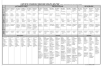
B245/B276/B277/B268/B269 Service Manual
18-Jan-06
Troubleshooting
Service Call Conditions
Summary
There are four levels of service call conditions.
Level
Definition
To prevent damage to the machine, the main
machine cannot be operated until the SC has
been reset by a service representative (see the
note below).
If the SC was caused by incorrect sensor
detection, the SC can be reset by turning the
main power switch off and on.
The main machine can be operated as usual,
excluding the unit related to the service call.
The SC history is updated. The machine can be
operated as usual.
A
B
C
D
Reset Procedure
Enter SP mode, and then turn
the main power switch off and
on.
Turn the main power switch off
and on.
Turn the main power switch off
and on.
The SC will not be displayed.
Only the SC history is updated.
If the problem concerns electrical circuit boards, first disconnect then reconnect the
connectors before replacing the PCBs.
If the problem concerns a motor lock, first check the mechanical load before
replacing motors or sensors.
SC Code Descriptions
No.
Definition
Symptom
Possible Cause
Exposure Lamp Error
101
120
B
B
The standard white level
was not detected properly
when scanning the white
plate.
Exposure lamp defective
Exposure lamp stabilizer defective
Exposure lamp connector defective
Dirty scanner mirror or scanner
mirror out of position
SBU board defective
SBU connector defective
Lens block out of position
Incorrect position or width of white
p.141)
plate scanning (
Scanner home position error 1
The scanner home
Scanner home position sensor
position sensor does not
defective
detect the off condition
Scanner drive motor defective
117
B245/B276/B277/B268/B269 Service Manual
No.
Definition
Symptom
during initialization or
copying.
18-Jan-06
Possible Cause
Scanner home position sensor
connector defective
Scanner drive motor connector
defective
BICU board defective
Scanner home position error 2
121
B
143
D
144
B
145
D
193
B
198
B
302
B
Scanner home position sensor
defective
The scanner home
Scanner drive motor defective
position sensor does not
Scanner home position sensor
detect the on condition
connector defective
during initialization or
Scanner drive motor connector
copying.
defective
BICU board defective
SBU white/black level correction error
The automatic SBU
Exposure lamp defective
adjustment has failed to
Dirty white plate
correct the black level.
Incorrect position or width of white
The automatic SBU
adjustment has failed to
p.141)
plate scanning (
correct the white level
BICU board defective
twenty times
SBU board defective
consecutively.
Communication Error between BICU and SBU
The flat cable between the BICU
board and the SBU has a poor
The BICU board cannot
connection
detect the SBU connect
The flat cable between the BICU
signal.
board and the SBU is damaged
BICU board defective
SBU defective
Automatic SBU adjustment error
During the automatic SBU
Exposure lamp defective
adjustment, the machine
Dirty white plate
detects that the white
Incorrect position or width of white
level read from the white
p.141)
plate scanning (
plate or paper is out of
BICU board defective
p.141)
range. (
SBU board defective
Image transfer error
Scanned images are not
transferred to the
BICU board defective
controller memory within
Controller board defective
1 minute.
Memory address error
The BICU board does not
The firmware programs of the engine
receive memory
and the controller do not match.
addresses from the
BICU board defective
controller board.
Controller board defective
Charge roller current leak
A current leak signal for
Charge roller damaged
the charge roller is
High voltage supply board defective
118
B245/B276/B277/B268/B269 Service Manual
No.
Definition
320
B
321
C
322
B
390
B
391
B
392
B
401
B
402
B
Symptom
18-Jan-06
Possible Cause
detected.
Poor connection of the PCU
Polygonal mirror motor error
The polygon mirror motor
Polygon mirror motor defective
does not reach operating
Poor connection between the
speed within 10 seconds
polygonal mirror motor driver and the
after the motor ON signal
BICU board
is sent, or does not turn
Damaged cable between BICU and
on within one of the 200
polygonal mirror motor driver
ms check intervals during
BICU board defective
operation.
No laser writing signal (F-GATE) error
The laser-writing signal
BICU board defective
(F-GATE) fails to turn Low
The fax controller or printer controller
after the laser crosses 5
has a poor connection
mm on the drum surface
Fax controller or printer controller
from the laser writing start
defective
position.
Laser synchronization error
The main scan
Poor connection between the LD unit
synchronization detector
and the BICU board
board cannot detect the
Damaged cable between BICU and
laser synchronization
LD unit
signal for more than 5
LD unit out of position
consecutive 100 ms
LD unit defective
intervals.
BICU board defective
TD sensor error
The TD sensor outputs
less than 0.2 V or more
TD sensor abnormal
than 4.0 V 10 times
Poor connection of the PCU
consecutively during
copying.
Development bias leak
A development bias leak
Poor connection of the PCU
signal is detected.
High voltage supply board defective
TD sensor initial setting error
ID sensor defective
No developer
Drum does not turn
TD sensor initial setting is
Development roller does not turn
not performed correctly.
Poor connection of the PCU
The voltage is not applied to charge
roller
Transfer roller leak error 1
A current leak signal for
High voltage supply board defective
the transfer roller is
Poor connection of the PCU
detected.
Transfer/separation unit set
A current feedback signal
incorrectly
for the transfer roller is
Transfer roller damaged
not detected.
Transfer roller leak error 2
119
B245/B276/B277/B268/B269 Service Manual
No.
Definition
500
B
502
C
503
C
504
C
506
C
541
A
542
A
Symptom
18-Jan-06
Possible Cause
A current leak signal for
High voltage supply board defective
the transfer roller is
Poor connection of the PCU
detected.
Transfer/separation unit set
A current feedback signal
incorrectly
for the transfer roller is
Transfer roller damaged
not detected.
Main motor lock
A main motor lock signal
is not detected for more
than 7 consecutive
checks (700 ms) after the
Too much load on the drive
main motor starts to
mechanism
rotate, or the lock signal is
Main motor defective
not detected for more
than 7 consecutive
checks during rotation
after the last signal.
Tray 2 lift motor malfunction (Optional paper tray units)
The paper lift sensor fails
Paper lift sensor defective
to activate twice
Tray lift motor defective
continuously after the tray
Too much load on the drive
lift motor has been on for
mechanism
18 seconds.
Poor tray lift motor connection
Tray 3 lift motor malfunction (optional paper tray units)
The paper lift sensor fails
Paper lift sensor defective
to activate twice
Tray lift motor defective
continuously after the tray
Too much load on the drive
lift motor has been on for
mechanism
18 seconds.
Poor tray lift motor connection
Tray 4 lift motor malfunction (optional two-tray paper tray unit)
The paper lift sensor fails
Paper lift sensor defective
to activate twice
Tray lift motor defective
continuously after the tray
Too much load on the drive
lift motor has been on for
mechanism
18 seconds.
Poor tray lift motor connection
Paper feed motor lock (optional paper tray units)
A motor lock signal is not
Paper feed motor defective
detected for more than
1.5 s or the lock signal is
Too much load on the drive
not detected for more
mechanism
than 1.0 s during rotation.
Fusing thermistor open (center)
The fusing temperature
Fusing thermistor defective or out of
detected by the thermistor
position
is below 71C and is not
Power supply board defective
corrected after the main
Loose connectors
power switch is turned on.
Fusing temperature warm-up error (center)
The fusing temperature
Fusing thermistor defective or out of
rises less than 7 degrees
position
in 2 seconds, and this
Fusing lamp open
120
B245/B276/B277/B268/B269 Service Manual
No.
Definition
543
A
544
A
545
A
546
A
547
B
551
A
552
A
Symptom
18-Jan-06
Possible Cause
continues 5 times
Power supply board defective
consecutively.
The fusing temperature is
not detected in 25 or 35
seconds.
Fusing overheat error (center)
The fusing temperature is
over 230C for 1 second
Fusing thermistor defective
(detected by the
Power supply board defective
thermistor).
Fusing overheat error (center) 2
The fusing temperature is
over 250C for 1 second
Fusing thermistor defective
(detected by the fusing
Power supply board defective
temperature monitor
circuit).
Fusing lamp overheat error (center)
After the fusing
temperature reaches the
Fusing thermistor defective or out of
target temperature, the
position
fusing lamp does not turn
Power supply board defective
off for 12 consecutive
seconds.
Unstable fusing temperature (center)
The fusing temperature
Thermistor defective or out of
varies 50C or more within
position
1 second, and this occurs
Power supply unit defective
2 consecutive times.
Zero cross signal malfunction
Zero cross signals are not
detected within 5 seconds
after the main power
Power supply board defective
switch is turned on, or are
BICU defective
not detected within 1
second after operation
begins.
Fusing thermistor open (rear)
The fusing temperature
Fusing thermistor defective or out of
detected by the thermistor
position
is below 71C and is not
Power supply board defective
corrected after the main
Loose connectors
power switch is turned on.
Fusing temperature warm-up error (rear)
The fusing temperature
rises less than 7 degrees
in 2 seconds, and this
Fusing thermistor defective or out of
continues 5 times
position
Fusing lamp open
consecutively.
Power supply board defective
The fusing temperature is
not detected in 25 or 35
seconds.
121
B245/B276/B277/B268/B269 Service Manual
No.
Definition
553
A
555
A
556
A
559
590
B
591
B
620
B
621
B
Symptom
18-Jan-06
Possible Cause
Fusing overheat error (rear)
The fusing temperature is
over 230C for 1 second
Fusing thermistor defective
Power supply board defective
(detected by the
thermistor).
Fusing lamp overheat error (rear)
After the fusing
temperature reaches the
Fusing thermistor defective or out of
target temperature, the
position
fusing lamp does not turn
Power supply board defective
off for 20 consecutive
seconds.
Unstable fusing temperature (rear)
The fusing temperature
Thermistor defective or out of
varies 50C or more within
position
1 second, and this occurs
Power supply unit defective
2 consecutive times.
Jam error detected 3 times in succession
The exit sensor and Paper jams can occur for the following
the duplex sensor
reasons.
detect a paper jam 3
Dampness
times in succession
Paper curl
This condition can
Incorrect paper setting in the paper
occur when SP 1159
tray
1 is set to ‘on’. The
Stripper pawls coming apart
default is ‘off’.
Left exhaust fan motor error
The CPU detects an
Loose connection of the exhaust fan
exhaust fan lock signal for
motor
more than 5 seconds.
Too much load on the motor drive
Rear exhaust fan motor error
The CPU detects an
Loose connection of the exhaust fan
exhaust fan lock signal for
motor
more than 5 seconds.
Too much load on the motor drive
Communication error between BICU and ADF
The BICU does not
receive a response from
Poor connection between the BICU
the ADF main board for 4
and ADF main board (DF connector)
seconds or more.
ADF main board defective
The BICU receives a
BICU defective
break signal from the ADF
main board.
ADF connection error
An incorrect ADF (an ADF
ADF incorrect (The ADF for
for some other copier) is
B039/B040/B043 or
detected. (for Basic and
B121/B122/B123 is installed on a
GDI machines)
B245/B268/B269/B276/B277.)
An ADF (including the
The connector of the ADF is
correct ADF) is installed
removed while the machine is in the
while the copier is in the
energy saver mode.
122
B245/B276/B277/B268/B269 Service Manual
No.
Definition
632
C
633
C
634
C
635
B
670
C
692
B
694
760
B
761
B
762
B
Symptom
18-Jan-06
Possible Cause
energy saver mode. (for
GDI machine only)
Accounting error 1
An error is detected
Accounting device defective
during the communication
with the MF accounting
Loose connection
device.
Accounting error 2
After communication is
established with the MF
Accounting device defective
accounting device, a
Loose connection
brake signal is issued.
Accounting RAM error
An error is detected in the
RAM that saves the
Accounting device defective
information on the MF
accounting.
Accounting battery error
An error is detected in the
battery that is in the MF
Accounting device defective
accounting device.
Engine start error
The engine-ready signal
Engine board defective
is not issued within 70
Controller defective
seconds after the switch
Loose connection
is turned on.
Controller board communication abnormal
Communication error
The connector is abnormal between
between the printer part
the controller board and the BICU
of the controller board
board.
and BICU.
Controller board communication abnormal
Communication error
The connector is abnormal between
between the scanner part
the controller board and the BICU
of the controller board
board.
and BICU.
ADF gate abnormal 1
ADF main board defective
The ADF Gate signal line
Input/output board defective
between the ADF main
Poor connection (ADF Gate line)
board and the BICU is
between the ADF main board and
disconnected.
the BICU.
ADF gate abnormal 2
The FGATE signal is not
ADF connector defective
issued from the ADF
within 30 seconds after
SBU board defective
the ADF starts feeding.
ADF gate abnormal 3
The FGATE signal is not
ADF connector defective
terminated by the ADF
SBU board defective
123
B245/B276/B277/B268/B269 Service Manual
No.
Definition
800
B
804
B
818
B
819
B
820
B
821
B
823
C
824
B
826
B
Symptom
18-Jan-06
Possible Cause
within 60 seconds after
the ADF starts feeding.
Startup without video output end error
Video transfer to the
engine is started, but the
engine did not issue a
Controller board defective
video transmission end
command within the
specified time.
Startup without video input end
A video transmission was
requested from the
scanner, but the scanner
Controller board defective
did not issue a video
transmission end
command within the
specified time.
Watchdog error
The CPU does not
Controller board defective
access the watchdog
Software malfunction – download
register within a certain
controller firmware again
time.
Kernel mismatch error
Software bug
Download controller firmware again
Self-Diagnostic Error: CPU
The central processing
unit returned an error
Controller board defective
during the self-diagnostic
Download controller firmware again
test.
Self-Diagnostic Error: ASIC
The ASIC returned an
error during the selfdiagnostic test because
Controller board defective
the ASIC and CPU timer
interrupts were compared
and determined to be out
of range.
Self-diagnostic Error: Network Interface
The network interface
Network interface board defective
board returned an error
during the self-diagnostic
Controller board defective
test.
Self-diagnostic Error: NVRAM
The resident non-volatile
Replace the NVRAM on the
RAM returned an error
controller board
during the self-diagnostic
Replace the controller board
test.
Self-diagnostic Error: NVRAM/Optional NVRAM
The NVRAM or optional
Replace the NVRAM on the
NVRAM returned an error
controller board
124
B245/B276/B277/B268/B269 Service Manual
No.
Definition
827
B
828
B
829
C
838
B
850
C
857
C
900
B
901
B
903
B
920
C
921
C
928
B
Symptom
18-Jan-06
Possible Cause
during the self-diagnostic
test.
Self-diagnostic Error: RAM
The resident RAM
returned a verify error
Download controller firmware again
during the self-diagnostic
test.
Self-diagnostic Error: ROM
The resident read-only
memory returned an error
Controller board defective
during the self-diagnostic
Download controller firmware again
test.
Self-diagnostic Error: Optional RAM
The optional RAM
Replace the optional memory board
returned an error during
Controller board defective
the self-diagnostic test.
Self-diagnostic Error: Clock Generator
A verify error occurred
when setting data was
Replace the controller board
read from the clock
generator via the I2C bus.
Network I/F Abnormal
NIB defective
NIB interface error.
Controller board defective
USB I/F Error
USB interface error
Defective controller
detected.
Electrical total counter error
The electrical total
NVRAM on the GDI controller board
counter does not work
defective
properly.
Mechanical total counter
Mechanical total counter defective
The mechanical total
BICU defective
counter does not work
Disconnected mechanical total
properly.
counter
Engine total counter error
The checksum of the total
NVRAM on the BICU defective
counter is not correct.
Printer error
A fatal error is detected in
Printer application program defective
the printer application
Hardware configuration incorrect
program
(including memory shortage)
Printer font error
Necessary font files are
Font file not installed
not found.
Memory error
The machine detects a
Memory defective
discrepancy in the
BICU defective
write/read data during its
Poor connection between BICU and
125
B245/B276/B277/B268/B269 Service Manual
No.
Definition
954
B
955
B
964
B
981
B
982
B
984
B
990
B
991
D
Symptom
18-Jan-06
Possible Cause
write/read test (done at
memory
power off/on and at
recovery from low power
or night/off mode).
Printer application program error
The printer status does
not become ready when
the printer application
Application program defective
program is necessary for
image processing.
Image transfer error
The controller is not able
to transfer images when
Application program defective
the engine needs them.
Status error (laser optics housing unit)
The optics-housing unit
does not become ready
Software defective
within 17 seconds after
the request.
NVRAM error
The machine detects a
NVRAM defective
discrepancy in the
Poor connection between BICU and
NVRAM write/read data
NVRAM
when attempting to save
NVRAM is not connected
actual data to the NVRAM
BICU defective
(i.e. during actual use).
Localization error
The localization settings
First machine start after the NVRAM
in the nonvolatile ROM
is replaced
and RAM are different
Incorrect localization setting
NVRAM defective
(
p.146).
Print image transfer error
Controller defective
Print images are not
BICU board defective
transferred.
Poor connection between controller
and BICU
Software performance error
Software defective
Internal parameter incorrect
Insufficient working memory
When this SC occurs, the file name,
The software attempted to
address, and data will be stored in
perform an unexpected
NVRAM. This information can be
operation.
checked by using SP 7403. Note the
above data and the situation in
which this SC occurs. Then report
the data and conditions to your
technical control center.
Software continuity error
The software attempted to
No operation required. This SC code
126
B245/B276/B277/B268/B269 Service Manual
No.
Definition
992
B
997
B
998
B
999
B
Symptom
18-Jan-06
Possible Cause
perform an unexpected
does not appear on the panel, and is
operation. However,
only logged.
unlike SC990, the object
of the error is continuity of
the software.
Unexpected Software Error
Software encountered an
Software defective
unexpected operation not
An error undetectable by any other
defined under any SC
SC code occurred
code.
Application function selection error
The application selected
Download the firmware for the
by a key press on
application that failed
operation panel does not
An option required by the application
start or ends abnormally.
(RAM board) is not installed
Application start error.
After power on, the
Download controller firmware
Replace the controller board
application does not start
within 60 s. (All
An option required by the application
applications neither start
(RAM board) is not installed
nor end normally.)
Program download error
Board installed incorrectly
BICU board defective
Controller board defective
IC card defective
NVRAM defective
Loss of power during downloading
Important Notes About SC999
Primarily intended for operating in
The download (program,
the download mode, logging is not
print data, language data)
performed with SC999.
from the IC card does not
If the machine loses power while
execute normally.
downloading, or if for some other
reason the download does not end
normally, this could damage the
controller board or the PCB targeted
for the download and prevent
subsequent downloading. If this
problem occurs, the damaged PCB
must be replaced.
127