1
SPIDER MAX 500 - EURO 3
EURO 3
1
07/06
SPIDER MAX 500 - EURO 3
FOREWORD
• The present manual concerns all the necessary procedures aimed at identifying electrical (Electronic Injection)
system failures and possible interventions for their resolution and provides to the service personnel (of Authorised
Service Centres) the main information to work in compliance with the modern concepts of “good service” and “work
safety”.
• For further information refer to the Service Manual - Cycle Parts, the Engine Service Manual and the Spare Part
Catalogue.
• All the operations described below must be carried out by skilled and experienced personnel.
• The procedures for the removal of bodywork and/or electrical and mechanical parts in order to access electrical cables
or components are described in the Service Manual - Cycle Parts.
• We suggest following strictly the indications contained in the present document.
• For any further information, contact Malaguti S.p.A. Service Assistance.
• It is important to adhere strictly to the following instructions. Any operation carried out carelessly or not carried out at
all may lead to personal injury, damage to the motorcycle or simply to unpleasant complaints.
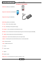
REFERENCE NOTES
PAGE CONFIGURATION
X
X Motorcycle model
Y
Y Section
W Page no.
Z
Release date
ABBREVIATIONS USED IN THE
MANUAL
F
P
Pr
S
Sch
T
Picture
Page
Paragraph
Section
Diagram
Table
W
Z
MODIFIED PAGES
• Modified pages are indicated by the same number of the page in the previous edition, followed by an M and the new
release date.
• It is possible that new pictures are inserted in the modified pages; if it is the case, the new picture (or pictures) will have
the same number of the previous picture/s followed by a letter of the alphabet.
• In case of number omission, the picture number will be displayed on a black ground (e.g.: F. 5 ).
ADDED PAGES
• Added pages are indicated by the last number of their section followed by an A and the new release date.
2
07/06
SPIDER MAX 500 - EURO 3
OPERATION SYMBOLS
IMPORTANT!
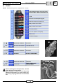
WARNING! - Used to indicate dangerous operation that can lead to the injury of service staff, workshop personnel
or people in general or damage to the facility, the motorcycle or equipment.
ENGINE OFF - Used for all the operations that must be carried out with engine off.
VOLTAGE OFF - Disconnect the battery negative pole before the operation.
MECHANICAL SERVICE STAFF - Operations that must be carried out by a skilled mechanic.
ELECTRICAL SERVICE STAFF - Operations that must be carried out by a skilled electrician or electronic
technician.
NO! - Do not carry out this operation.
WARNING
• Before any operation, make sure that the motorcycle is in a perfectly stable position.
We suggest to anchor the front wheel to the equipment fixed to the lifting platform.
• Use only well-known quality instruments to perform checks and calibrations and not empirical or not fully reliable
equipments.
• “Malaguti S.p.A.” cannot be held responsible for any damage resulting from the use of inadequate testing equipments
for the check of electrical/electronical system.
• “Malaguti” reserves the right to change its motorcycles in any moment without prior notice.
Any (even partial) reproduction or distribution of the topics or pictures contained in the present manuals is strictly
forbidden. The manual content is covered by copyright, any reproduction and use of reproductions must be authorised
in written form by ”Malaguti”.‘
FIRST EDITION: 07/06
3
07/06
SPIDER MAX 500 - EURO 3
TECHNICAL DICTIONARY
• Multimeter (Tester) (cod. 08609500)
• Diagnostic multimeter (cod. 08607500)
• Diagnostic wiring (cod. 08607600)
• Master Key (red key cod. 09007000)
• V = (DC) : Direct current (battery supply)
• V ~ (AC) : Alternating current (flywheel supply)
• A : Ampere = Unit of measurement of the electrical current
• W : Watt = Unit of measurement of the electrical power (product of Volts and Amperes; A x V = W)
• Ω : OHM = Unit of measurement of the electrical resistance
• OHM infinito = Disconnected multimeter prods or interrupted cable
• OHM = 0 : Continuity with connected multimeter prods or not interrupted cable
• PIN : Connector terminal
• Linea : Cable across two pins
• < = Lower
• ≤ = Lower or equal
• > = Higher
• ≥ = Higher or equal
• KPa (or bar) : Unit of measurement of pressure (100 Kpa = 1 bar)
4
07/06
SPIDER MAX 500 - EURO 3
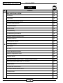
INDEX
S
A
TOPICS
P
DIAGNOSTICS
7
Main menu functions
7
Secondary menu functions
10
Alarm functions
11
Set-up menu
14
Selection of the unit of measurement and software revision
17
Analog equipment: speedometer
17
Warning led function
17
Backlight function
18
Sequence of the described functions
18
System start-up
18
Sleep-Mode
18
Equipment first installation
18
Testing procedure
19
Electrical characteristics
19
Dashboard connector configuration
20
Battery (12V - 14 Ah)
21
Sealed battery
23
Immobasic technical specifications
24
Relays
25
Fuses
26
General electrical diagram
27
Electrical start-up
28
Lights and battery recharge
29
Parking lights - Direction indicators - Horn button Speed sensor - Anti-theft configuration
30
5
07/06
SPIDER MAX 500 - EURO 3
INDEX
S
B
TOPICS
P
EMS INJECTION SYSTEM
31
Introduction
31
Precautions
32
EMS central unit terminal layout
33
Injection system diagram
33
Component layout
34
General notes
36
Troubleshooting
44
Troubleshooting procedures
45
Injection central unit supply circuit
53
Injection led circuit
57
Autodiagnostic System
59
Fuel supply system
61
Rpm sensor
87
H.T. coil
91
Coolant temperature sensor
97
Intake air temperature sensor
101
Pressure sensor
105
Gas valve position sensor (T.P.S. = Throttle Position Sensor)
106
Gas valve position signal reset (T.P.S. reset)
110
Stepper motor
112
Electrical fan control circuit
117
Revolution counter control circuit
121
Lambda sensor
124
6
07/06
SPIDER MAX 500 - EURO 3
1.
DIAGNOSTICS
A
MAIN MENU FUNCTIONS
(digital dashboard)
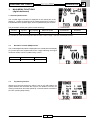
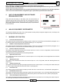
1.1 Current speed function
The 3-coded digits information is displayed on the central part of the
display (F. 1) while the selected unit of measurement (Km/h or Mph) is
indicated above the speed 3 digits, which is updated every 0.5 seconds.
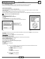
F. 1 Initial screen
The parameters used by the system are the followings:
Circumf.
Imp./rev.
CT [imp/min]
Maximum speed
Overestimate
Resolution
1.828 mm
6
54,70
180 Km/h - 111 Mph
5% constant
1 Km/h - 1 Mph
CT= impulses per minute that the equipment needs to receive in order to display 1 real Km/h (overestimate excluded).
1.2
Revolution counter (RPM) function
The 3-coded digits information is displayed on the central part of the display
(F 2) while “Rpmx100” appears above the 3 digits indicating the engine
revolution number, which is updated every 0,5 sec.
Refresh
500 m/sec
Full scale
10.000 rpm
Resolution
100 rpm
F. 2 RPM function
1.3
Trip memory function
Starting from the moment the key switch is set on the “ON position, the
system detects and calculates the trip time, the distance covered, the
motorcycle maximum and mean speeds (F. 3) until the switch is set back to
the “OFF” position (sleep-mode).
F. 3 Trip memory
7
07/06
A
SPIDER MAX 500 - EURO 3
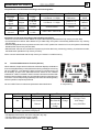
The parameters are calculated according to the following table:
Function
Maximum
speed
Mean
Speed
Trip
time
Distance
covered
Digits
3 Digits
4 digits
Resolution
1 Km/h
1 Mph
0.1 Km/h
0.1 Mph
Maximum value
Refresh
Icon
180 Km/h - 111 Mph
5000 m/sec
MAX
180 Km/h - 111 Mph
100m se v>0
5 sec se v=0
MEAN
4 digits
(hh:mm)
1 minute
99 hours 59min
1 minute
Clock
icon
5 digits
0.1 Km
0.1 Mi
9999.9 Km - 9999.9 Mi
0.1 Km - 0.1 Mi
-
Information can be reset according to the following procedures:
• Distance covered overflow: after 99h59' the system automatically deletes all the Trip memory function data.
• Covered distance overflow: after 9999.9 Km (or 9999.9 Mi), the system automatically deletes all the Trip memory
function data.
• Extended Sleep Mode: if the key switch remains on the “OFF“ position for more than 2 hours, the system automatically
deletes all the Trip memory function data.
• Manual Reset: the user can reset all the Trip memory function data in any moment by pressing, for at least 2 seconds,
the Mode button (beside the Trip memory function).
All the counters associated with the trip memory are saved in a volatile memory.
1.4
Preventive Maintenance Function (Service)
When selected, the preventive maintenance indicator displays the distance
to be covered (decreasing counter) before the warning messages concerning
OIL and V.BELT (F. 4) are displayed. More precisely, it indicates when it will
be necessary to refer to an authorised service centre for OIL CHECK/
CHANGE or V. BELT CHANGE. When both the indicators associated with
these two alarms display 0000, the corresponding warning message turns
on and the counter stops being updated (it will continue indicating 0000),
until the operation required is performed.
OIL and V. BELT Service follows the parameters described below:
Oil
V. Belt
I coupon
Distance
Type
After 1000
Change
Km
F. 4 Trip memory
II coupon
III coupon
Following
Distance
Type
Distance
Type
After 2000 Check After 3000
Alternate Check
Km from the
Km from the Change
and Change
first one
second one
every 3000 Km
change
Every 12000 Km a message prompting to replace the transmission belt to the converter
(“Change” type alarm) is displayed.
• The displayed information cannot be changed in any way.
• The information is expressed in Km or Miles.
• The value is stored in a non-volatile memory.
8
07/06
A
SPIDER MAX 500 - EURO 3
1.5
Radiator coolant temperature indicator function (WTEMP)
The information is displayed in graphic mode (by a ten-segment bar on the left hand side of the display) and by the
switching on of the radiator coolant indicator (see F. 1). This function is displayed with any function selected or warning
message on. Failure to connect the resistive sensor to the equipment is indicated by the blinking of the led and of the
corresponding icon on the display (f=1Hz, duty=50%). In order to avoid displaying wrong readings, the sensor is read
every 10 sec and the graphic bar is updated 1 segment by one. This means that, in case the sensor resistive value
suddenly shifts from the maximum to the minimum value, it will take 90 seconds to display the 10 segments.
A temperature below 35 °C will be displayed by the partial switching on of the first segment of the graphic bar.
When the 10th segment is displayed, the led and the entire bar start blinking. The graphic bar operation is indicated in the
following table:
1.6
Temperature
No. of segments
Sensor resistive value
<35°C
35°C ÷ 45°C
1 (partial)
1
> 1650Ω
From 1650Ω to 1000Ω
45°C ÷ 55°C
2
From 999Ω to 770Ω
55°C ÷ 70°C
3
From 769Ω to 400Ω
70°C ÷ 80°C
4
From 399Ω to 301Ω
80°C ÷ 90°C
5
From 300Ω to 216Ω
90°C ÷ 105°C
105°C ÷ 110°C
6
7
From 215Ω to 151Ω
From 150Ω to 130Ω
110°C ÷ 115°C
8
From 129Ω to 112Ω
115°C ÷ 119°C
9
From 111Ω to 95Ω
≥120°C
10 + Led
≤ 94Ω
Fuel level indicator function (FUEL)
The information is displayed in graphic mode (by a ten-segment bar, on the right hand side of the display) and by the
switching on of the fuel icon (see F. 1). This function is displayed with any function selected or warning message on.
Failure to connect the resistive sensor to the equipment is indicated by the blinking of the led and of the corresponding
icon on the display (f=1Hz, duty=50%). The sensor is read every 5 sec and the bar is updated one segment by one. In
order to avoid displaying wrong readings, caused by the fuel fluctuations in the tank, the graphic bar is updated only
when the detected fuel level remains constant during three following readings with respect to the current reading. In case
the sensor resistive value suddenly shifts from the maximum to the minimum value it will take 15sec*10 segments=150
seconds to display the 10 segments.
The 1st segment indicates the fuel reserve and cause the corresponding led to go on.
9
07/06
A
SPIDER MAX 500 - EURO 3
The graphic bar function is describe below:
Capacity
No. of segments
Sensor resistive value
3l ÷ 4l
1+Led
From 100Ω to 69Ω
4l ÷ 5l
2
From 68Ω to 61Ω
5l ÷ 6l
3
From 60,9Ω to 54Ω
6l ÷ 7l
4
From 53,9Ω to 47Ω
7l ÷ 8l
8l ÷ 9l
5
6
From 46,9Ω to 40Ω
From 39,9Ω to 33Ω
9l ÷ 10l
7
From 32,9Ω to 26Ω
10l ÷ 11l
8
From 25,9Ω to 19Ω
11l ÷ 12l
9
From 18,9Ω to 12Ω
≥ 12l
10
≤ 11Ω
2.
SECONDARY MENU FUNCTIONS
2.1
Totaliser function (TOD)
The information is displayed on the lower part of the display along with the icon TOD, as shown in F. 1. The 5-coded digit
information is permanently stored in a non-volatile memory.
• If no data is stored in the memory the number 00000 is displayed.
• The information is expressed in Km or Miles (the equipment automatically converts the information into the required
UM).
• This information cannot be reset during the normal use of the equipment.
• The displayed information resolution is 1 Km (1Mi)
2.2
Trip Function (TD)
The information is displayed on the lower part of the display along with the icon TD, as shown in F. 2. The 4-coded digit
information is stored in a volatile memory. It is possible to reset the counter associated with this parameter by selecting
the trip function and holding the button down until the value 000.0 appears (this procedure cannot be used after selecting
the Trip memory function). Resetting is possible both with the motorcycle in motion and still.
• If no data is stored in the memory the number 000.0 is displayed.
• The information is expressed in Km or Miles (the equipment automatically converts the information into the required
UM).
• The counter is reset and restarts after exceeding the number 999.9.
• The TD value IS NOT stored in the memory.
• The displayed information resolution is 0.1 Km (0.1Mi).
10
07/06
A
SPIDER MAX 500 - EURO 3
2.3
Air temperature function
The information is displayed on the lower part of the display along with the
icon TEMP. The 2-coded digit (plus sign) information is stored in a volatile
memory and is always expressed in Celsius degrees.
When the sensor is not properly connected to the equipment two horizontal
dashes are displayed instead (F. 5).
• Strategy: the actual temperature detected by the sensor is displayed.
• The displayed function cannot be changed in any way.
• The information is updated every 0.5 sec.
• Displayed limits: -10 °C…..+ 55 °C.
• Measure tolerance: ±1°C.
2.4
F. 5 Outside temperature
Clock function (TIME)
The information concerning the current time is displayed on the upper part of the display, in hh:mm format (see F. 1). To
adjust the current time, switch the motorcycle off and access the set-up menu.
• Displayed sequence: from 0:00 to 23:59.
• The information concerning the current time IS NOT stored in the memory.
• Clock precision: ± 2.5"/day.
• The Time function is always visible, except with the Preventive Maintenance function on.
3.
ALARM FUNCTION
3.1
ICE Alarm
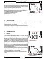
In case the sensor reads a temperature below 4 °C, the system starts the
alarm routine to warn that there could be ice on the street: with any function
displayed, the system shows the message *** ICE (F. 6), which blinks for 15
seconds (f=1 Hz, duty=50%). After the indicated period of time, the display
goes back to the function previously displayed while the * ICE icon moves
to the lower left hand side of the display (and all the information usually
displayed on this area will be moved to make room for the new blinking
information (f=1 Hz, duty=50%) (see F.7). This configuration aims at warning
the user that there may be ice on the street, but does not affect the equipment
operation in any way: in fact all its functions are available beside the warning
message. The alarm situation ends when the sensor reads a temperature
above 5 °C. The whole sequence will be repeated every time that the read
temperature is below or equal to 4°C and is interrupted whenever the read
temperature is above or equal to 6°C.
• While the warning message is on (15 sec.), the button function is disabled.
• While the warning message is on (15 sec.), the only functions that persist
on the display are “Fuel” (fuel level indicator), “wtemp” (radiator coolant
temperature) and hydraulic stand alarm (when present).
• The alarm is displayed with any function selected.
• When the selected function is “Service”, the alarm routine stops after
15 sec.
F. 6 ICE alarm (after 15")
F. 7 ICE alarm (after 15")
11
07/06
A
SPIDER MAX 500 - EURO 3
3.2
Oil Check / Oil Change Alarm
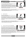
The system is configured to show messages concerning the need for a
check to be performed, as explained in paragraph 1.4.
The routine allows displaying the service icon along with the message OIL
CHANGE or OIL CHECK going on and blinking (f=1 Hz, duty=50%) according
to the type of alarm. The warning message lasts for 1 minute and goes on
only when the key switch is on the “ON” position (F. 8). This algorithm will
stay on until the Dealer who carries out the service operations, as indicated
in paragraph, disables it. 6.4. After showing the message, the previously
selected information will be displayed again.
F. 8 OIL Service Alarm
• While the warning message is on (60 sec.), the button function is disabled.
• While the warning message is on (60 sec.), the only functions that persist on the display are “Fuel”(fuel level indicator),
“wtemp” (radiator coolant temperature) and “hydraulic stand alarm” (when present).
• The alarm is displayed with any function selected.
3.3
V.Belt Change Alarm
The system is configured to show messages concerning the need for a
check, as described in paragraph 1.4.
The routine allows displaying the service icon together with the message
V.BELT CHANGE going on and blinking (f=1 Hz, duty=50%) (F. 9). The
warning message lasts for 1 minute and goes on only when the key switch
is on the “ON” position. This algorithm will stay on until the Dealer who
carries out the service operations, as indicated in paragraph 6.5, disables
it. After showing the message, the information previously selected will be
displayed again.
F. 9 V.BELT Service Alarm
• While the warning message is on (60 sec.), the button function is disabled.
• While the warning message is on (60 sec.), the only functions that persist on the display are “Fuel” (fuel level indicator),
“wtemp” (radiator coolant temperature) and “hydraulic stand alarm” (when present).
• The alarm is displayed with any function selected.
3.4
Oil pressure indicator alarm (OIL LOW PRESSURE)
Every time that the sensor is closed to ground and Rpm10 is displayed,
the corresponding warning message is shown on the display. The routine
displays the blinking message OIL LOW PRESSURE (f=1 Hz, duty=50%),
and the oil icon (F. 10). In order to avoid displaying false warning messages,
this message appears only when the pressure switch remains closed to
ground for a period of time not below 1.5 ÷ 2.0 seconds. The warning
message will stay on until the sensor signal will be low (= ground), or until
Rpm10 is reached. If the motorcycle engine is not running (Rpm =0), no
warning message is displayed even if the pressure switch is closed to
ground. In order to allow checking the equipment operation, the pressure F. 10 OIL Alarm
switch closing is indicated during the 8 seconds subsequent to the key
switch shift to the “ON” position, no matter whether there is signal on the rev. counter cable. After 8 seconds, the alarm
will be displayed together with the number of rpm.
12
07/06
A
SPIDER MAX 500 - EURO 3
The alarm is displayed with any function displayed.
• While the warning message is on (60 sec.), the button function is disabled.
• While the warning message is on(60 sec.), the only functions that persist on the display are
“Fuel”(fuel level indicator), “wtemp” (radiator coolant temperature) and “hydraulic stand alarm” (when present).
• The alarm is displayed with any function selected.
3.5
Battery low alarm (VBATT)
When the battery charge is below the programmed threshold value the system starts the alarm routine. The battery icon
is displayed along with the message LOW on the upper right hand side of the display (F. 1). This alarm signal does not
affect the normal operation of the dashboard and is displayed with any selected function (in case the selected function
is “Preventive Maintenance”, only the battery icon is displayed - F. 4). The alarm situation ends when the charge exceeds
again the threshold value.
3.6
Simultaneous alarms
In case of simultaneous alarms a different class of priority is given to each type of alarm described in the previous
sections. More precisely the “hydraulic stand” alarm is given Priority 1 (the highest), while the OIL LOW PRESSURE and
ICE alarms are given Priority 2 (lower than the previous one); the OIL CHECK/CHANGE and V. BELT CHANGE alarms
are given Priority 3 and the “battery low” alarm is given Priority 4 (the lowest). The table below shows the different
classes of priority:
Alarm
Hydraulic stand
Priority
1 (HIGH)
OIL low pressure
2
ICE
2
OIL check/change
3
V. BELT change
Low Battery
3
4 (LOW)
Imagining that all the types of alarm occur together, the system will act as follows:
• The “hydraulic stand” alarm icon is always displayed, no matter if any other alarm is on.
• The warning message OIL LOW PRESSURE and ICE alternates every 5 seconds, while all the other alarms (OIL
CHECK/CHANGE, V.BELT CHANGE and battery low) are set in the memory queue.
• After the ICE alarm (which lasts only 15 sec.), only the OIL LOW PRESSURE is displayed while all the other alarms
(OIL CHECK/CHANGE, V.BELT CHANGE and “battery low”) are set in the memory queue. In case the OIL BAR alarm
(pressure switch opened or Rpm=0 rev./min.) only the ICE alarm is displayed while all the other alarms (OIL CHECK/
CHANGE, V.BELT CHANGE and “battery low”) are set in the memory queue.
• Only when the two alarms with Priority 2 (OIL LOW PRESSURE and ICE) go off, the system starts managing the
alarms with Priority 3 (OIL CHECK/CHANGE and V.BELT CHANGE), alternating them every 5 seconds for a total
duration of one minute each. The alarms with Priority 4 (“battery low”) are set in the memory queue.
• Only when all the alarms with Priority 3 (OIL CHECK/CHANGE and V.BELT CHANGE) go off, the system starts
managing the alarms with Priority 4 (“battery low”) that are displayed according to the methods above described.
• After the alarm sequence is over, the system restores the display normal operation mode.
While the alarms with Priority 2 and 3 (ICE, OIL LOW PRESSURE, V.BELT CHANGE and OIL CHECK/CHANGE) are
on, the button function is disabled.
13
07/06
A
SPIDER MAX 500 - EURO 3
4.
SET-UP MENU
This menu allows accessing a series of functions used to:
• Adjust the current time (TIME).
• Adjust the equipment backlight (BACKLIGHT).
• Adjust display contrast and display mode (DISPLAY).
• Indicate to the system that Oil service has been performed (OIL).
• Indicate to the system that the variator belt has been replaced (V.BELT).
F. 11 Set-up menu
It is possible to access the Set-up menu only when the motorcycle is not in motion by pressing the mode button beside
the TOD function for around 2 seconds, until the Set-Up screen is displayed (F. 11). Then press again the mode button to
scroll the different functions until the needed function is displayed and press the button for around 2 seconds until the
adjustment mode appears. After the adjustment operations are over, press the button beside the EXIT function for at
least 2 seconds to go back to the standard operation mode.
Note 1: if the button is not pressed within 20 seconds from accessing the adjustment menu, the system
automatically goes back to the standard operation mode.
Note 2: if the motorcycle engine is started (speed>0) after accessing the adjustment menu, the system automatically
goes back to the standard operation mode.
Note 3: It is not possible to access the set-up menu when the “Trip memory” function is selected.
4.1
Current time adjustment (TIME)
To adjust the current time press the mode button beside the message
TIME (in the Set-Up window) for at least 2 seconds. At this point the only
information displayed will be the current time (F. 11), blinking (f=1Hz,
duty=50%). A short pressure of the mode button allows changing the hour
value while a longer pressure (of at least 2 seconds) allows changing the
minutes (that will be then be blinking), in the same way described for the
hours. Press the button beside the EXIT function (for at least 2 seconds)
to go back to the Set-up menu.
Note 1: if the button is not pressed within 20 seconds from accessing
the adjustment menu, the system automatically goes back to the
standard operation mode.
Note 2: if the motorcycle engine is started (speed>0) after accessing
the adjustment menu, the system automatically goes back to the
standard operation mode.
14
07/06
F. 12 TIME adjustment
A
SPIDER MAX 500 - EURO 3
4.2
Backlight adjustment (BACKLIGHT)
To adjust the backlight the low beams (and then the equipment backlight)
must be lit. In this condition, press the mode button beside the word
BACKLIGHT (in the Set-Up window) for at least 2 seconds to adjust the
backlight (coded by a graphic bar, as shown in F. 13) and press for a short
time the mode button until the required value is reached. To go back to the
Set-up menu simply press the mode button for at least 2 seconds.
F. 13 Backlight adjustment
Note 1: If the low beams are switched off after accessing the adjustment menu, the system escs the adjustment
function and save the last value set by the user.
Note 2: if the button is not pressed within 20 seconds from accessing the adjustment menu, the system
automatically goes back to the standard operation mode.
Note 3: if the motorcycle is started (speed>0) after accessing the adjustment menu, the system automatically
goes back to the standard operation mode.
4.3
Display contrast and mode adjustment (DISPLAY)
In order to adjust the display contrast and mode (Normal or Reverse image)
simply press the mode button beside the word DISPLAY (in the Set-up
window) for at least 2 seconds.
Two modes are possible for the display contrast adjustment (F. 14):
1) Automatic (default): the contrast optimal value, displayed by means of
the graphic bar, is set automatically.
F. 14 Display adjustment
2) Manual: the user can adjust the required contrast value, displayed by means the graphic bar, manually. Actually it is
a semi-automatic adjustment as, according to the display temperature function, the system allows the user adjusting
the value only within a given range that ensures the display visibility.
The automatic mode is set as default value. To select the manual mode simply press the mode button beside the
word “Manual” for at least 2 seconds until a triangle, which indicates that the selection has been made, is displayed
beside the same word. A short pressure of the mode button allows adjusting the required value.
Two different display mode adjustment procedures are possible:
1) Normal (default): only the necessary parts of the display are switched on while all the others (in the background) are
switched off.
2) Reverse: it is the negative image of the previous mode where all the parts in the background are switched on while the
parts selected to be displayed are switched off.
The Normal mode is set as default value. To select the negative image mode by simply pressing the mode button
beside the word “Reverse” for at least 2 seconds until a triangle which indicates that the selection has been made is
displayed beside the same word.
After the adjustment operations are over, press the button beside the EXIT function for at least 2 seconds to go back
to the standard operation mode.
Note 1: if the button is not pressed within 20 seconds from accessing the adjustment menu, the system
automatically goes back to the standard operation mode.
Note 2: if the motorcycle engine is started (speed>0) after accessing the adjustment menu, the system automatically
goes back to the standard operation mode.
15
07/06
A
SPIDER MAX 500 - EURO 3
4.3.1 Display mode quick selection
The selection procedure of the (Normal or Reverse) display mode described in the previous paragraph could result quite
difficult, for this reason, considering that the user may need to change the display mode quite often, a quick selection
routine has been implemented allowing the user to carry out this operation while driving. This routine can be selected
only when the STAND-BY function is selected. In the described situation, if the button is not pressed within 5 seconds,
the system will display the TOD function. If the button is pressed for less than 2 seconds, the system changes the main
menu function; if the button is pressed for more than 2 seconds, the system goes to the Set-up menu display function
(F. 14), where the only options that can be selected are Normal and Reverse. It is possible to exit the menu in two ways:
1) without pressing the button within 20 seconds;
2) by selecting a display mode.
This procedure allows the user changing the display mode (from Normal to Reverse and vice versa) by simply holding
the button down (after selecting the STAND-BY function) and without looking at the display. This routine, in fact, can be
performed while driving and thus be quite dangerous for the user that could move his/her attention from the road to the
display.
4.4
OIL ALARM de-activation (OIL)
The de-activation of the OIL CHECK or CHANGE ALARM must be performed only by authorised personnel according to
the following procedure:
• Position the key switch on the “OFF” position.
• With the key on the “OFF” position, press the mode button.
• Holding the mode button down, move the key to the “ON” position.
At this point, the system will display the Set-up menu (F. 11), from which it is possible to select the OIL function (only
OIL, V.BELT and EXIT can be selected). It is then possible to de-activate the OIL Alarm by pressing the button for at
least 2 seconds. This procedure allows the authorised Dealer to inform the system that the service operations have been
carried out and generates a confirmation message (OIL ALARM OFF) that will lasts for at least 15".
Note 1: While the confirmation message is on, the button function is disabled.
Note 2: The OIL ALARM can be de-activated at any time without waiting for the decreasing counter, associated
with this function, to get to the zero.
Note 3: After de-activating the alarm, the system automatically sets the equipment to the standard operation
mode. To access the de-activation configuration again, repeat all the operations above described.
4.5
V.BELT ALARM de-activation (V.BELT)
The V.BELT CHANGE ALARM de-activation must be performed only by authorised personnel according to the following
procedure:
• Position the key switch on the “OFF” position.
• With the key on the “OFF” position, press the mode button.
• Holding the mode button down, move the key to the “ON” position.
At this point, the system will display the Set-up menu (F. 11), from which it is possible to select the V.BELT function (only
OIL, V.BELT and EXIT can be selected), it is then possible to de-activate the V.BELT Alarm by pressing the for at least
2 seconds. This procedure allows the authorised Dealer to inform the system that the service operations have been
carried out and generates a confirmation message (V.BELT ALARM OFF) that will lasts for at least 15".
16
07/06
A
SPIDER MAX 500 - EURO 3
Note 1: While the confirmation message is on, the button function is disabled.
Note 2: The V.BELT ALARM can be de-activated at any time without waiting for the decreasing counter, associated
with this function, to get to the zero.
Note 3: After de-activating the alarm, the system automatically sets the equipment to the standard operation
mode. To access the de-activation configuration again, repeat all the operations above described.
5.
UNIT OF MEASUREMENT AND SOFTWARE
REVISION SELECTION
Every time that the battery or the battery fuse are disconnected, the
equipment prompts the user to select the unit of measurement (Km/h or
Mph) by pressing the button while the main menu is displayed. The (oneletter coded) software revision, release week and year (F. 15) are shown in
the same window.
6.
F. 15 Unit of measurement and Software
Revision selection
ANALOG EQUIPMENT: SPEEDOMETER
The equipment displays the value of the current speed in analog mode, through the stepper motor, according to the
same principles described in paragraph 1.1.
7.
7.1
WARNING LED FUNCTION
Fuel level indicator function
The system receives the information prompting to switch on the micro control device, as described in paragraph 1.6. If
the resistive sensor is disconnected, the led starts blinking (f=1 Hz, duty=50%).
7.2
Radiator coolant temperature led function
The system receives the information prompting to switch on the micro control device, as described in paragraph 1.5. If
the resistive sensor is disconnected, the led starts blinking (f=1 Hz, duty=50%).
7.3
Direction indicator led function
The system must activate the led when the connector inputs no. 2 and no. 16 are in a high state, when the direction
indicators are switched on (see page 20).
The signal reaching the equipment must be already alternate.
7.4
High beam led function
The system must activate the led when the connector input no.15 is in a high state, when the high beams are switched
on (see page 20).
7.5
Beam function led
The system must activate the led when the connector input no. 3 is in a high state, when the switching beams are
switched on.
7.6
Injection function led
The system receives the information prompting to switch the micro control device on, according to the state of the input
no. 20; a low logic state determines the led to switch on (see page 20).
7.7
Oil function led
The system receives the information prompting to switch the micro control device on, as described in paragraph 5.6.
7.8
Immobilizer function led
The system receives the information prompting to switch the connector input no. 22 on; a low logic state determines the
led to switch on. The led can be turned on even when the key switch is moved to the “OFF” position (see page 20).
7.9
Side stand/engine stop function led
The system receives the information prompting to switch the micro control device on according to the state of input no.
12; a low logic state determines the led to switch on.
17
07/06
A
SPIDER MAX 500 - EURO 3
8.
BACKLIGHT FUNCTION
8.1
LCD backlight function
The liquid crystal backlight is always on (unless the key switch is moved to the “OFF” position).
8.2
Dashboard backlight function
The dashboard backlight goes on only when the parking lights are turned on.
9.
SEQUENCE OF THE DESCRIBED FUNCTIONS
To scroll the functions press the Mode button according to the sequence indicated in the table below
Mode
TOD
TD
TEMP
STAND-BY
SPEED
Mode
RPM
TRIP MEMORY
SERVICE
As already said in the previous chapters:
• It is possible to access the Set-up menu only when the motorcycle is not in motion (speed=0). It is not possible to enter
the Set-up menu when the “Trip memory” function is selected.
• It is possible to reset the partial distance both with the motorcycle in motion or still. After selecting the TD function,
reset the value by holding the button down (for around 2 seconds) until the number 000.0 is displayed. It is not possible
to reset the TD function when the “Trip memory” function is selected.
• It is possible to reset the “Trip memory” both with the motorcycle in motion or still. After selecting the “Trip memory”
function, reset the value by holding the button down (for around 2 seconds) until all the items of the function (distance
covered, maximum and mean speed) are set to zero.
10. SYSTEM START-UP
When starting the engine (moving the key from the “OFF” to the “ON” position), the system will:
• check for the leds and backlight operation: for 3 sec all the leds are switched on (leds, backlight, immobilizer led,
except the injection led, that is managed directly by the motorcycle central unit).
• Display the “Malaguti” Logo for around 1,5 seconds.
• Display the “Spider Max” Icon and the selected unit of measurement for around 1.5 seconds.
• Display the warning message “OIL BAR” (if the pressure switch is closed to ground) for 8 seconds, whether there is
signal on the revolution counter cable.
• The system is set to the standard display.
11.
SLEEP-MODE
Every time that the key switch is turned to the “OFF” position, the system:
• searches for the mechanical zero of the engine.
• switches off all the active leds, the dashboard backlight and the 12V output, where present.
• switches to a “sleep mode”, with power low consumption, system inactivity. The only function that remains on is the
current time up dating.
12.
EQUIPMENT FIRST INSTALLATION
The first time that the equipment is connected to the battery, all the pixels contained in the display are checked for
around 5 seconds, and consequently the user is prompted to select one of the units of measurement (also the software
revision is displayed in the same window).
18
07/06
A
SPIDER MAX 500 - EURO 3
13.
TESTING PROCEDURE
This is a procedure very useful for a quick and reliable testing of the equipment inputs and the speedometer movement.
To access the procedure follow the rules indicated below:
• Disconnect the equipment from the motorcycle battery.
• Connect the testing cable to ground (line no. 23)
• Restore the connection to the battery.
At this point, the system performs a display check by switching on the pixels, not all together, but line by line (each line
made of 4 elements). When the testing is over, the system prompts the operator to insert the unit of measurement and,
after displaying the “Malaguti” logo and the motorcycle icon, shows the current speed and the total covered distance
(TOD). The functions cannot be scrolled and, every time that the button is pressed, the system checks for the operation
of the leds (all leds, except the immobilizer led) and the speedometer. The latest covers all the scale travel (from the zero
to the full scale value) and back. The testing routine ends when the equipment switches to the sleep mode. Whenever the
key switch is moved to the to “ON” position again, the system switches to the standard operation mode, even if the
testing cable is still connected to ground.
14.
ELECTRICAL CHARACTERISTICS
General operating characteristics
Param.
No.
Characteristic
Icon
Min.
Max
Units
PM1
Max. operating voltage
VMAX
¾
17
V
PM2
Operating temperature
TSto
-20
+85
°C
PM3
Max power generated by PIN 16
20
mA
PM4
PM5
Max power that can be applied to inputs
Max power that can be applied to outputs
¾
¾
20
20
mA
mA
IHall
IInMax
IoutMax
General operating characteristics
Param.
No.
Characteristic
Icon
Min.
Typ.
Max
PO1
Supply voltage
VDD
6.0 (1)
12,0
16.0
V
PO2
Operative Temperature
TOp
-20
¾
+80
°C
PO3
Power consumption on the “ON” position
with all the leds on (Battery voltage=12,5V)
Ion
¾
¾
470
mA
PO4
Power consumption on the “ON” position
Ion_leds
with all the leds on (Battery voltage=12,5V)
Power consumption in Sleep mode
Islp
(Battery voltage=12,5V)
¾
¾
120.2
mA
¾
¾
1
mA
PO5
Units
(1) This parameter represents the minimum value of voltage that can be applied to the input without affecting the
equipment operation. When said value is reached the optoelectronics components of the system (warning leds and
backlight) are off.
19
07/06
A
SPIDER MAX 500 - EURO 3
15.
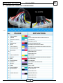
DASHBOARD CONNECTOR CONFIGURATION
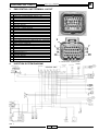
No. 24 PIN
F. 16
COLOUR
No.
APPLICATIONS
1
YELLOW/RED
RPM
2
GREEN
RIGHT HAND SIDE DIRECTION INDICATOR
3
FAIR BLUE/WHITE
LOW BEAMS
4
PINK
PARKING LIGHTS
5
RED/BLACK
OUTSIDE TEMPERATURE
6
BLUE
KEY SWITCH POSITIVE CABLE
7
YELLOW/BLUE
ODOMETER TRANSMISSION SENSOR SUPPLY
8
WHITE/PURPLE
OIL PRESSURE
9
BLUE/RED
BATTERY POSITIVE CABLE
10
-
DISCONNECTED
11
-
DISCONNECTED
12
YELLOW/GREEN
SIDE STAND
13
WHITE
ODOMETER TRANSMISSION SENSOR SIGNAL
14
RED
BUTTON MODE
15
WHITE/BLACK
HIGH BEAMS
16
17
PURPLE
BLACK
LEFT DIRECTION INDICATOR
GROUND
18
GREY
FUEL LEVEL
19
WHITE/GREEN
DIRECTION INDICATOR
20
BLACK/BLUE
INJECTION LED
21
-
DISCONNECTED
22
PURPLE/BLACK
IMMOBILIZER LED
23
-
DISCONNECTED
24
-
DISCONNECTED
20
07/06
A
SPIDER MAX 500 - EURO 3
16. BATTERY (12V - 14 AH)
NOTE - The following information concerns the interventions on “non sealed” battery type.
The battery electrolyte contains sulphuric acid with is poisonous and can cause severe burnt. Avoid that
the substance get in contact with eyes, skin or clothes. In case of contact with eyes or skin rinse thoroughly
with water for some minutes and refer to a doctor. In case of ingestion, immediately drink a lot of water or
milk followed by milk of magnesia, beated egg or vegetal oil and call a doctor.
The battery produces explosive gases; do not use bare flames, sparks or cigarettes; ventilate the room
while recharging the battery in a closed environment. Always screen the eyes when working in the proximity
of batteries. Keep out of the reach of children.
• After removing hose and caps, pour battery-type sulphuric
acid into the elements until reaching the upper level. The
acid specific weight must be 1.26, that is to say 30 Bé,
and its temperature below 15 °C.
F. 17
1) Keep the densitometer in a vertical position.
2) Visually check the liquid density.
3) Release the float.
1
• Leave the battery rest for at least 2 hours and then top up
with sulphuric acid.
• Recharge with a proper recharger within 24 hours at a
voltage corresponding to around 1/10 of the battery rated
capacity until the acid density reaches the value 1.27,
that is to say to 31 Bé.
2
3
• After recharging the battery, top up the acid (adding
distilled water). Close with the cap and clean with care.
• Once the above operations are over, fit the battery to the
motorcycle, according to the wiring diagram indicated in
the Service manual.
Black cables
Red cables
battery (-) pole
battery (+) pole
F. 18
16.1
Electrolyte level check
• Frequently check for the electrolyte level: it must reach the upper part of the battery. In order to top up the indicated
level strictly use distilled water. In case water need to be added with unusual frequency, check for the motorcycle
electrical system operation: the battery may be surcharged and this may reduce its lifetime.
21
07/06
A
SPIDER MAX 500 - EURO 3
16.2
Battery charge check
After topping up the electrolyte level, check the liquid density by means of a densitometer.
When the battery is fully charged, the electrolyte density should be around 30 ÷ 32 Bé, which correspond to a specific
weight of 1.26 ÷ 1.28, at a temperature below 15 °C.
In case the measured density is below 20° Bé, the battery is completely flat and it is then necessary to recharge it.
In case the motorcycle is not used for certain period of time (1 month or over), remember to recharge the battery every
now and then.
The battery runs completely flat within 3 months. When fitting the battery back to the motorcycle make sure the
cables are not inverted and always remember to connect the ground cable (black), with the (-) mark to the negative terminal, and the remaining two red cables, with the (+) mark, to the + positive terminal.
Before recharging the battery, remove all the element caps. Do not use bare flames, or sparks while recharging
the battery.
Remove the battery from the motorcycle by disconnecting the negative terminal first.
To recharge the battery after disassembling it, use the specific recharger. Make sure to move the battery
recharger switch to the type of battery to be recharged (that is to say, with a voltage corresponding to 1/10
of the battery rated capacity). Make sure to match the poles (“+” with “+” and “-” with “-”) when connecting
to the power supply.
We suggest to keep the battery clean, especially on its upper part and to protect the terminals with vaseline.
Never use fuses exceeding the recommended rated capacity. Failure to observe this rule may damage the
motorcycle and/or represent explosion hazards.
Ordinary and drinkable water contains mineral salts that are corrosive to batteries. Never use a water type
different from distilled water.
In order to ensure the battery best performances, recharge it before use. Failure to observe this indication
before assembling it to the motorcycle may reduce the battery lifetime.
22
07/06
A
SPIDER MAX 500 - EURO 3
17.
SEALED BATTERY
17.1 Sealed battery
The service operations simply concern the checking and recharging of the battery, when necessary.
These operations must be performed at the pre-delivery stage and every 6 months in case the motorcycle is
stored with the circuit open.
Besides pre-delivery checks, it is then necessary to check for the battery charge and to recharge it before storing
the motorcycle and then every 6 months.
“RENEWAL” RECHARGE AFTER STORING THE MOTORCYCLE WITH OPEN CIRCUIT
1) Voltage check
Before fitting the battery to the motorcycle, check the open circuit voltage by means of a common multimeter.
• In case the voltage is above 12,6 V, fit the battery without recharging it.
• In case the voltage is below 12,6 V, the battery needs a “renewal” recharge. Proceed as follows:
2) Using a constant-voltage battery recharger.
- Recharge at constant voltage equal to 14,40 ÷ 14,70V;
- Initial recharge current = 0,3 ÷ 0,5 x rated capacity;
- Duration of recharge:
Suggested 10 ÷ 12 h;
Minimum 6 h;
Maximum 24 h.
3) Using a constant-current battery recharger.
- Recharge current equal to 1/10 of the battery rated capacity.
23
07/06
A
SPIDER MAX 500 - EURO 3
18.
18.1
“IMMOBASIC” TECHNICAL SPECIFICATIONS
Storing the keys for the first time
The device gets ready to store the two user keys immediately after connecting it to the power supply for the first time or
until the two user keys have not been stored.
The LED stays on during the operation: it only switches off for a few seconds after storing the first and then the second
key, blinking for three seconds - at 1Hz - to indicate that the two operations ended successfully and then it switches off
completely.
In case the second key is not stored within two minutes from the device switching on or from the first key storing, the
system holds the routine, and deletes the code entered for the first key. The entire procedure will then have to be
repeated from the beginning next time the key is switched to ON.
The same is true in case of power failure happening while storing the first key and before the second key code is entered.
When the power is restored, the system acts as it was the first switching on and prepares to store the data.
After storing the first key, the system excites the relays in order to allow starting the engine, in the motorcycle assembly
line, without closing the routine.
18.2
Storing more keys
After performing the storing procedures described in paragraph 18.1, the system can be configured to store from one to
four additional user keys.
In order to enable this function it is necessary to insert the MASTER KEY (cod. 09007000) within 10 seconds from the
last “key-off”, made by using the valid key used as “key-on”.
In this way, the memory buffer is reset and all the keys that need to be stored as valid keys, included the one
entered and recognised as MASTER KEY, must be inserted and switched to the “ON” position. After inserting the
master key, the LED turns and stays on, switching off for a few seconds after every successful storing operation.
The routine closes after storing the fourth key or thirty seconds from the last key storing, and the LED switches off for
three seconds, blinking in succession - at 1 Hz - a number of times corresponding to the number of stored keys.
All the data are actually stored in the memory only when closing the routine: the key codes, entered before starting the
procedure, are thus stored even in case of power failure before closing the same.
18.3
Losing the keys
In case the keys are lost except at least one enabled key, follow the procedures described in paragraph 18.2 to update
the memory with the codes of the new keys that need to be enabled.
In case all enabled keys are lost, it will be necessary to replace the entire device: (Keylock kit + Immobilizer).
18.4
Led blinking
In order to avoid that the battery runs down quickly, the LED that indicates that the ”immobilizer” function is enabled,
stops blinking after 20 days.
24
07/06
A
SPIDER MAX 500 - EURO 3
19.
RELAYS
• The motorcycle is equipped with 5 relays located under the driver seat (see Service Manual – Cycle Parts).
• Each relay support has a different colour that indicates the relay specific function:
Starter permissive relay.
Starter permissive relay.
H.T. coil, injector, fuel pump supply.
Radiator fan supply
F. 19
19.1 Starter relay (A)
F. 19/a
NOTE - A 30A fuse (battery recharge protection) is located on the starter relay.
In case the relay needs to be replaced, make sure
to match the cable connection colours: red and
blue.
RED -
(battery
starter relay):
connect to the (B) pole of the relay.
BLUE -
(starter relay
starter motor)
connect to the (M) pole of the relay.
9
F. 20
Inverting the cables interrupts the battery recharge operation.
25
07/06
A
SPIDER MAX 500 - EURO 3
20.
FUSES
NOTE - The Electrical system is equipped with 11 fuses.
NO.
PROTECTED CIRCUITS
Lights
Direction indicators/parking lights
Dashboard electrical central unit
Relay: White - Red - Yellow
Relay: White - Red - Yellow
12 V (key switch)
H.T. coil - Injector - Fuel pump
Radiator fan
Central unit supply
F. 21
10
No.
20
No.
22
PROTECTED CIRCUITS
LOCATION
BATTERY RECHARGE
STARTER RELAY
PROTECTED CIRCUITS
LOCATION
GENERAL
BATTERY COMPARTMENT
F. 22
No.
23
PROTECTED CIRCUITS
LOCATION
12 V PLUG
UNDER THE HELMET
COMPARTMENT
11
Before replacing the interrupted fuse, find and
repair the cause of interruption.
Never attempt to replace the fuse by using
different components (e.g. a piece of wire) or a
fuse having amperage above the recommended
one.
F. 23
26
07/06
Flashing light
Flywheel
Regulator
Keylock
07/06
Anti-theft
configuration
27
BATTERY
Left switches
Left
direction
indicator
Low/high
beam
Regulator frame ground
knot
black
white
yellow
Low/high
beam
red
Right
direction
indicator
Diode
Dashboard
connector
H20
temperature
Injection
Right switches
Left
direction Parking
Stop/
light
indicator
parking Plate light
light
Helmet
compartment
light
Odometer sensor signal
Engine stop/stand
Key switch
+ odometer sensor
Mode
RAR-OIL
LED IMMOBASIC
Fuel level
Dashboard
Stop/
parking
light
Cigarette lighter plug
Fan
Lambda
sensor
Central unit
ground
Side cable
CENTRAL UNIT
Starter motor
IMMOBASIC
antenna in
the keylock area
Parking Right direction
indicator
light
Tail light wiring
Stop light switch
Frame ground
in the coil
area
Outside
temperature
sensor
Pick- up
transmission
Parking light
Fuel injector
Idling adjusting
motor
Engine
temperature
sensor
Throttle
potentiometer
Diagnostics
Fuel level indicator +
pump
Sch. 1
COLOR LEGEND
Anti-tilting
sensor
Oil pressure sensor
Air temperature
sensor
Engine
revolution
sensor
H.T. coil
21.
Horn button
Stop light
switch
SPIDER MAX 500 - EURO 3
A
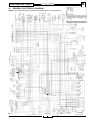
GENERAL ELECTRICAL DIAGRAM
NOTE - The present diagram is repeated on two pages at the end of the Manual.
+ 12 Direct to battery
Stop light
switch
28
black
REGULATOR FRAME
GROUND KNOT
Dashboard
connector
white
Diode
Stop light
switch
Starter relay
Tail light wiring
Right switches
Starter motor
Side cable
IMMOBASIC antenna in the
keylock area
SPIDER MAX 500 - EURO 3
A
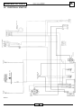
22. ELECTRICAL START-UP
Sch. 2
07/06
Frame ground
in the coil area
Engine stop/
stand
BATTERY
Keylock
Sch. 3
29
07/06
Regulator
Keylock
Low/high
beam
Regulator frame
ground knot
Low/high
beam
Parking light
Starter relay
Parking
light
Helmet
compartment light
Dashboard
connector
Plate light
Parking
light
Tail light wiring
Right switches
23.
Flywheel
Starter
motor
Left switches
SPIDER MAX 500 - EURO 3
A
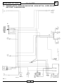
LIGHTS AND BATTERY RECHARGE
Cigarette lighter plug
+ 12 Direct to battery
BATTERY
Sch. 4
30
07/06
Flashing light
Horn button
Stop light
switch
Keylock
Frame ground
in the coil
area
Anti-theft
configuration
BATTERY
Left switches
white
Left
direction
indicator
Starter solenoid
valve
Left direction
indicator
Stop/
parking
light
Right
direction
indicator
Key switch
Right direction indicator
Left direction indicator
Stop/
parking
light
Tail light wiring
Ground
Odometer sensor signal
Right direction
indicator
+ odometer sensor
Dashboard
connector
Stop light switch
SPIDER MAX 500 - EURO 3
A
24. PARKING LIGHTS - DIRECTION INDICATORS - HORN BUTTON – SPEED SENSOR ANTI-THEFT CONFIGURATION
Pick- up
transmission
Regulator frame
ground knot
SPIDER MAX 500 - EURO 3
1.
EMS INJECTION SYSTEM
B
INTRODUCTION
The injection system is of the integrated injection and ignition system type.
The injection is indirect into the intake manifold through electro-injector.
Injection and ignition are timed on the 4-stroke cycle by means of a phonic wheel splined to the camshaft control and a
reluctance change sensor.
Carburetion and ignition are managed according to the motor revolutions and the gas valve opening.
Further corrections are made according to the following parameters:
- Coolant temperature;
- Intake air temperature;
- Room pressure.
The system corrects the fuel supply at idling and cold engine by means of a stepper motor set on a by-pass circuit of the
gas valve. The central unit controls the stepper motor and the injector opening time, thus ensuring stability at idling
speed and correct carburetion.
In all operating conditions, the carburetion control depends on the changing of the injector opening.
The fuel supply pressure is kept constant in relation to the room pressure.
The supply circuit is made of:
- a fuel pump;
- a fuel filter;
- an injector;
- a pressure regulator.
The pump, filter and regulator are assembled inside the fuel tank by means of a single support.
The injector is connected by means of two quick coupling hoses that allows getting a continuous circulation, avoiding
thus that the fuel gets to its boiling point. The pressure regulator is fitted to the end of the circuit.
The fuel pump is operated by the EMS central unit which ensures a safe motorcycle operation.
The ignition circuit components are:
- H.T. coil;
- H.T. cable;
- Shielded cap;
- EMS central unit;
- Spark plug.
The EMS central unit controls the ignition with the optimal spark advance, thus ensuring the 4-stroke timing (ignition
occurs only during the compression phase).
The EMS injection-ignition system controls the engine operation by means of a preset program. Should any of the input
signals miss, a basic engine operation is ensured in order to allow the driver reaching the nearest service centre.
Obviously this is not possible in case the engine rpm/speed signal is missing or when the anomaly inthe control circuits
of the:
- fuel pump
- H.T. coil
- injector.
31
07/06
B
SPIDER MAX 500 - EURO 3
2.
1.
PRECAUTIONS
Before any intervention on the injection system, check for any anomaly recorded.
Do not disconnect the battery before performing the anomaly check.
2.
The fuel supply system pressure is 300 KPa (3 BARS). While disconnecting the quick coupling of the fuel supply
system hose, do not use bare flames and do not smoke. Be careful, the fluid may splash and get in contact with
the eyes.
3.
While servicing the electrical components, do not leave the battery connected unless it is strictly necessary.
4.
When checking the operation functions, make sure that the battery voltage is above 12V.
5.
Before trying to start up the engine, make sure that the tank contains at least 2 litres of fuel. Failure to observe
this precaution may damage the fuel pump.
6.
In case the motorcycle is not used for a certain period of time, refill the tank up to half of its capacity so that the
pump is plunged into the fuel.
7.
While washing the motorcycle, do not pour water on electrical components and cables.
8.
In case of anomalies in the ignition system, first check the battery and the injection system connections.
9.
Before disconnecting the EMS central unit connector, carry out the following operations, in the indicated order:
- Position the key switch on the “OFF” position;
- Disconnect the battery;
Failure to observe this instruction may damage the central unit.
10.
When reassembling the battery, take care not to invert the poles.
11.
In order to avoid any damage, avoid disconnecting and reconnecting the EMS system connectors unless it is
strictly necessary.
Before reconnecting them, check connectors for humidity.
12.
While performing electrical checks, do not force the multimeter prods into the connectors. Do not carry out any
measurements not indicated by the Manual.
13.
After performing the test by means of the diagnostic multimeter, remember to protect the system connector with
the special cap. Failure to observe this rule may damage the EMS central unit.
14.
Before reconnecting the fuel supply quick couplings, check that the terminals are properly cleaned.
32
07/06
B
SPIDER MAX 500 - EURO 3
3.
EMS CENTRAL UNIT TERMINAL LAYOUT
“EMS” CENTRAL UNIT
No. FUNCTION
1
2
3
4
5
6
7
8
9
10
11
12
13
14
15
16
17
18
19
20
21
22
23
24
25
26
THROTTLE POTENTIOMETER SUPPLY (+5V)
NEGATIVE - LAMBDA SENSOR
DIGITAL INSTRUMENT (REV. COUNTER CONTROL)
ENGINE TEMPERATURE (+)
SOLENOID STARTER OF H.T. COIL INJECTOR PUMP
STEPPER MOTOR
RPM SENSOR
POSITIVE - LAMBDA SENSOR
EMS DIAGNOSTIC CONNECTOR
EMS DIAGNOSTIC CONNECTOR
POTENTIOMETER THROTTLE SIGNAL
RPM SENSOR
INJECTOR CONTROL (NEGATIVE)
STEPPER MOTOR
INSTRUMENTATION UNIT (INJECTION LED - NEGATIVE)
ANTI-TILTING SENSOR (-)
BASIC SUPPLY (POSITIVE)
AIR TEMPERATURE SENSOR (+)
SOLENOID STARTER FAN
H.T. COIL (NEGATIVE CONTROL)
STEPPER MOTOR
SENSOR SUPPLY (-)
CENTRAL UNIT - NEGATIVE
STEPPER MOTOR
DASHBOARD SUPPLY (POSITIVE)
F. 1 Connector - Central unit side
2
F. 2 Connector - System side
INJECTION SYSTEM DIAGRAM
Throttle
potentiometer
Dashboard
CENTRAL UNIT
Fuel level
Dashboard
connector
Central unit
ground
Engine
temperature
sensor
Diagnostics
+ 12v dashboard
from immobilizer
Fuel level indicator
+ pump
4.
Injection
Regulator frame
ground knot
H.T. coil
Idling adjusting
motor
Fuel
injector
Engine
revolution
sensor
Frame ground in
the coil area
Keylock
Air temperature
sensor
BATTERY
Lambda
sensor
yellow
red
Anti-tilting
sensor
To the starter motor
Sch. 1
33
07/06
Fan
B
SPIDER MAX 500 - EURO 3
5.
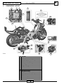
COMPONENT LAYOUT
2
3
4
8
9
5
1
15a
7
6
10
12
14
F. 2/a
13
15
11
Right hand side
1 Injection central unit
2 Starter permissive relay
3 Fuel pump, injector, coil relays
4 Electro-valve relay
5 Starter permissive relay
6 Anti-tilting device
7 Diagnostic plug
8 Fuses
9 Dashboard
10 Immobilizer decoder
11 Rpm/speed sensor
12 Idling control stepper motor
13 Throttle potentiometer (TPS)
14 Injector
15 Intake air temperature sensor
15a Horn
15b Lambda sensor
34
07/06
15b
B
SPIDER MAX 500 - EURO 3
17
16
18
19
20
21
22
23
F. 2/b
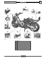
Left hand side
16 Key lock with Immobilizer antenna
17 Right control
18 12V plug
19 Fan
20 Fuel pump
21 Spark plug
22 Side stand switch
23 Engine temperature sensor
24 Coil
35
07/06
24
B
SPIDER MAX 500 - EURO 3
6.
GENERAL NOTES
The central unit is equipped with an autodiagnostic system
connected to a led on the dashboard (letter K - F. 3).
The EMS injection-ignition system also has a control
function on the revolution counter and the radiator cooling
fan.
F. 3
All anomalies can be detected and corrected by means of
the diagnostic multimeter (palmar instrument) code
08607500 (Piaggio code 020460Y).
In any case, once the anomaly is corrected it is
automatically deleted from the memory after 16 cycles of
use (start at cold engine, travel at warm engine, stop).
The diagnostic multimeter is fundamental also
to adjust the idling carburetion.
F. 4
The EMS central unit supply is managed by the emergency
switch (E) and by the side stand switch (D) to ensure a
safe motorcycle operation.
E
F. 5
To detect and solve any anomaly in the injection
system, along with the diagnostic multimeter also
use the testing wiring (code 08607600) (F. 6) supplied
by Malaguti S.p.A.
The above mentioned testing equipment allows carrying
out any check on the EMS central unit, even when the
motorcycle engine is running.
Place the testing wiring across the central unit connector
and the motorcycle system connector (see F. 6).
A = System connector
B = Central unit connector
F. 6
36
07/06
D
B
SPIDER MAX 500 - EURO 3
6.1
How to use the diagnostic multimeter (code 08607500)
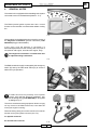
The EMS system diagnostic equipment (F. 4) is connected to the central unit by means of a EMS diagnostic plug
located under the driver seat (F. 2/a - page 34 - component no. 7).
Remove the protection cap and connect the diagnostic multimeter terminal.
F. 7
Supply the diagnostic multimeter by connecting the terminals to the battery poles, or the specific connector to the plug
located inside the helmet compartment (F. 7). Both supply cables are supplied with the motorcycle. (The system is
protected against polarity inversion).
The equipment starts up whenever it is connected to the power supply (no ON/OFF button present).
The system is equipped with a display, showing all the available functions, and the following push-buttons:
ESC
OK
UP
DOWN
TAB
Press the ESC button to leave the function or exit the displayed menu (except the main menu).
Press the OK button to confirm the selection made.
Press the UP and DOWN buttons to scroll the menu UP and DOWN.
Press the TAB button to display the menu functions.
Every time one of the buttons is pressed a Beep is heard: it indicates that the equipment received the command.
The DISPLAY shows 6 lines a time: a number displayed underneath any of the 6 lines indicates the number of the
function out of the total (e.g.: 1/ 7 indicates that the function displayed if the first out of the seven contained in the menu).
When starting up the equipment the MALAGUTI logo will be displayed.
Press any button to display the page containing all the information about the type of central unit the equipment was
designed for.
Press any other button or wait for 5 seconds to access the main menu.
At this point, scroll the menu by using the UP and DOWN buttons in order to select the required sub-menu and press the
OK button to access the sub-menu.
After accessing the sub-menu, select the required function and confirm by pressing the OK button again.
37
07/06
B
SPIDER MAX 500 - EURO 3
6.1.1 RESETTING THE ECU
In case it is necessary to replace the ECU or the throttle body, first reset the central unit.
To carry out the resetting procedure properly, follow the inStructions indicated below.
1) SELECTING THE MODEL
• Connect the diagnostic multimeter (COD.08607500)
(The diagnostic multimeter allows carrying out a number of checks on the injection system of various models)
• Select the vehicle
• Press the ESC and OK keys simultaneously and hold them pressed.
• Connect the diagnostic multimeter clamps to the battery: black clamp on the negative pole, red clamp on the positive pole.
WATCH OUT NOT TO INVERT THE POLES!
• The MAIN menu is displayed and
“ECU DIAGNOSTICS” (fig.7/a) highlighted
• Press OK
• The DIAGNOSTICS menu on the display shows the list
of vehicles on which it is possible to carry out the interventions (fig.7/b).
F. 7/b
F. 7/a
• To move the selection bar on the required model use the UP (to scroll up) and the DOWN (to scroll down) keys.
• Press OK
• The model description is displayed
• Press any key to access the MAIN menu of the selected model.
2) ECU RESETTING PROCEDURE
• After selecting the required model on the diagnostic multimeter, proceed as follows:
• Move the ENGINE STOP switch to Start.
• Release (close) the side stand
• Turn the light switch to OFF (lights off)
• Turn the ignition key to ON (without starting the engine)
• Select the ERROR function
• Press OK
• The ERROR menu is displayed.
• Check for errors
a) If any error is displayed, carry out the required service intervention and delete the errors.
• Select the DELETE ERROR function
• Press OK
• The DEL. ERROR menu is displayed.
• Press OK
• Press ESC
• The MAIN menu is displayed.
b) In case no errors are displayed
• Press ESC
• The MAIN menu is displayed.
38
07/06
B
SPIDER MAX 500 - EURO 3
3) T.P.S. RESETTING PROCEDURE:
• Select the T.P.S. RESETTING function
• Press OK
• The T.P.S. RESETTING menu is displayed.
• Check the throttle stroke by means of the handgrip (make sure that, when released, the handgrip returns to zero and
that the transmission has a certain play)
WARNING! In case the handgrip transmission is too tense the system acquires incorrect values on
the throttle angle thus detecting errors and anomalies
• Check that the throttle is at its max. stroke
• Press OK
• The message RESETTING OK, PRESS ANY KEY is displayed, this confirms that the operation ended with success.
WARNING! THE SUCCESS OF THE T.P.S. RESETTING PROCEDURE DOES NOT MEAN THAT THE
TRASMISSION FEATURES A CORRECT PLAY, IT SIMPLY CONFIRMS THAT THE ECU HAS ACQUIRED
THE NEW VALUE OF THE THROTTLE STROKE.
• If everything is correct, press OK
• The MAIN menu is displayed.
4) RESETTING THE STEPPER MOTOR
• Turn the ignition key to OFF and wait for around 2-4 seconds
• Turn the ignition key to ON (with the engine off)
• Now the stepper motor resetting procedure is ok
• Select the PARAMETER function
• Press OK
• The PARAMETER menu is displayed.
Ckech that the parameters are within the tolerance values (e.g.: Throttle angle value 5.24, temperature H20,
measured outside temperature, atmospheric pressure value acquisition, T.P.S. reset on YES and Lambda
sensor OPEN).
• Check that the parameters are correct
• Press ESC
• The MAIN menu is displayed.
•• Select the ACTIVE DIAGNOSTICS function
• Press OK
• The DIAGNOSTICS menu is displayed.
• Carry out the diagnosis on the following components:
I.
II.
III.
IV.
FUEL PUMP RELAY
H.T. COIL
FAN RELAY
RPM COUNTER
MAKE SURE THA AFTER EACH DIAGNOSTIC PROCEDURE THE MESSAGE ‘TEST ENDED WITH SUCCESS,
PRESS ANY KEY’ IS DISPLAYED ON THE POCKET PC
WARNING! COMPULSORY (FAN RELAY TEST).
N.B. The active diagnostics of the stepper motor can be carried out only with the engine warm and
with the water temperature above 80° C.
39
07/06
B
SPIDER MAX 500 - EURO 3
• Make sure that all the active diagnostics ended with success
• Press ESC
• The MAIN menu is displayed.
• Select the ERRORS function
• Press OK
• The ERRORS menu is displayed.
• Check for errors
a) If any error is displayed, carry out the required service
• Select the DELETE ERRORS function
• Press OK
• The DEL. ERRORS menu is displayed.
• Press OK
• Press ESC
b) If no error is displayed
• Press ESC
• The MAIN menu is displayed.
• Select the PARAMETERS function
• Press OK
• The PARAMETERS menu is displayed.
• Start th vehicle and speed up, checking that the engine rpm are ok, wait for the coolant temperature to exceed 50° C
and check the operation of beams, stop lights and other equipments.
N.B: the coolant temperature can be checked by means of the diagnosis tester
I.
II.
III.
IV.
Select the PARAMETERS function
Press OK
The PARAMETERS menu is displayed.
Check the WATER TEMPERATURE value
Make sure that the value measured by the diagnostics multimeter (WATER TEMP.) is the same indicated on the scooter
digital dashboard by the W Temp (the second segment of the graphic bar must be displayed).
If the fuel pump has not refilled or during the active diagnostics the air was not bleeded completely from the supply
system, it is necessary to carry out the fuel pump check several times.
To perform the pump check, turn the ignition key from ON to OFF.
In case the battery is low (but the current allows starting the vehicle) the engine idle speed may be quite irregular and
errors may be detected.
Leave the engine idling for at least 30 seconds in order to allow the system to carry out the self adaptation.
WARNING! Do not carry out any operation on the scooter components during this phase.
During self-adaptation, check the lambda sensor operation by making sure that LAMBDA STATUS IS CLOSED (the
loop on the reading must be closed) on the diagnostics sensor multimeter and the parameter ENGINE RPM (RPM) is
around 1500 g/min-1.
It is now possible to carry out the STEPPER MOTOR diagnostics (checking that the coolant temperature has reached
80°C).
WARNING! In case the CLOSED LOOP ( 0 ) is not displayed on the ADATT.TIT.OFFSET parameter, take note of all the
errors active or stored on the pocket pc, then reset the system and carry out the check once again.
• Turn the ignition key to OFF
WARNING! Wait for at least 30 seconds with the key on OFF before disconnecting, in the following order, the
diagnostics connector and, if necessary, the battery.
Leaving the key on OFF for 30 seconds in order to write in eeprom all the data of the routing just ended
(errors, self-adaptation values....).
40
07/06
B
SPIDER MAX 500 - EURO 3
6.2
Circuit diagram diagnostic plug
Central unit
ground
CENTRAL UNIT
+ 12v dashboard
from immobilizer
BATTERY
Regulator frame
ground knot
Sch. 2
41
07/06
Diagnostics
B
SPIDER MAX 500 - EURO 3
6.3
Connection circuit check of the “Diagnostic multimeter”
CENTRAL UNIT IS NOT
RESPONDING
CHECK CONNECTIONS
PARAMETERS
1/4
• In case the message “central unit is not responding” is displayed on the diagnostic
multimeter, cut the dashboard supply for 10 seconds and then switch it ON again. If the
warning message persists follow the instructions indicated below:
Check the diagnostic multimeter connectors and wiring:
A) Diagnostic plug
B) 12 Volt supply plug
A
B
A
F. 8
Restore connectors and/or wiring.
Check the central unit and dashboard
supply.
(See paragraph 9.1 - page 50 paragraph 9.2 - page 52).
Connect the testing wiring (code
08607600) to the motorcycle system
connector leaving the EMS central
unit disconnected.
F. 9
42
07/06
B
SPIDER MAX 500 - EURO 3
Verify the following conditions:
PIN 1 diagnostic plug - PIN 10 central unit = continuity
PIN 2 diagnostic plug - PIN 23 central unit = continuity
to ground
PIN 3 diagnostic plug - PIN 9 central unit = continuity
Ω)
PIN 10 - PIN 23 = insulation (> 1MΩ
Ω)
PIN 9 - PIN 23 = insulation (> 1MΩ
1
1
2
2
3
3
F. 10
Replace the central unit
Remove the interruption or short circuit cause
43
07/06
B
SPIDER MAX 500 - EURO 3
7.
TROUBLESHOOTING
7.1
Troubleshooting - tips
NOTE - A system failure concerning the EMS system may be more likely caused by faulty connections rather than
faulty components.
Before checking the EMS system for anomalies, carry out the following verifications:
A.
Electrical supply
- Battery voltage
- Burnt out fuse
- Solenoid starters
- Connectors
B.
Ground to chassis
C.
Fuel supply
- Faulty fuel pump
- Dirty fuel filter
D.
Ignition system
- Faulty spark plug
- Faulty coil
- Faulty shielded cap
E.
Intake circuit
- Dirty air cleaner
- Dirty by-pass circuit
- Faulty stepper motor
F.
Other
- Incorrect timing
- Incorrect idling carburetion
- Incorrect gas valve position sensor reset
NOTE - Most EMS system anomalies are caused by loose connectors. Make sure that all connections are properly
done.
Check connectors, taking special care to the following points:
1. check the terminals for bents.
2. check the connectors for proper plug in.
3. cause a slight vibration to the connector and verify whether the anomaly changes in any way.
Before replacing the EMS central unit, check for the whole system operation.
In case the anomaly disappears after replacing the EMS central unit, fit the previous central unit back and
verify whether the problems persists.
Use a multimeter with an inner resistance > 10KΩ for troubleshooting.
An improper equipment may damage the EMS central unit.
We suggest to chose equipments with a resolution above 0,1V and 0,5Ω. Resolution should always be
above ± 2%.
44
07/06
B
SPIDER MAX 500 - EURO 3
8.
8.1
TROUBLESHOOTING PROCEDURES
The engine does not start up even dragging the motorcycle.
Anomaly
Verifications
System not coded.
Immobilizer permissive
System failure.
Repair according to instructions.
Pump relay
H.T. coil
Anomalies detected by the injection
autodiagnostic system
Injector
Rpm / speed sensor
Fuel level in the tank
Fuel pump start up
Fuel supply
(low) fuel pressure
(Low) injector flow
H.T. coil shielded cap spark plug
(secondary insulation)
Spark plug supply
End of compression pressure
Coolant temperature
Parameter reliability
Timing - ignition injection
Intake air temperature
45
07/06
B
SPIDER MAX 500 - EURO 3
8.2
Difficult start up at cold and/or warm engine
Anomaly
Verifications
Pump relay
H.T. coil
Injector
Anomalies detected by the injection
autodiagnostic system
Rpm/ speed sensor
Air temperature
Coolant temperature
Atmospheric pressure
Starter motor and solenoid starter
Start up speed
Battery
Ground cables
End of compression pressure
Spark plug
Shielded cap
Spark plug supply
H.T. coil
Rpm/speed sensor
Spark advance
(Low) fuel pressure
Fuel supply
(Low) injector flow
(Unsufficient) injector sealing
Coolant temperature
Intake air temperature
Parameter reliability
Gas valve position
Stepper motor (steps and opening)
Secondary air duct and gas valve cleaning
Air cleaner efficiency
46
07/06
B
SPIDER MAX 500 - EURO 3
8.3
The engine stops when idling / Unstable idling speed / Idling speed too low
Anomaly
Verifications
Pump relay
H.T. coil
Injector
Anomalies detected by the injection
autodiagnostic system
Rpm/speed sensor
Air temperature
Coolant temperature
Atmospheric pressure
Spark plug
Ignition operation
Ignition timing
Gas valve position sensor
Stepper motor
Parameter reliability
Coolant temperature sensor
Intake air temperature sensor
Air cleaner
Intake system cleaning
Gas choke and valve
Secondary air duct and stepper motor
Intake manifold - head
Throttle body - manifold
Intake system sealing (leaks)
Intake hose
Airbox
Fuel pump
Pressure regulator
Fuel supply (low pressure)
Fuel filter
Injector flow
Analysis of exhaust gas before the catalytic converter
47
Trimmer value adjustment (CO % adjustment)
07/06
B
SPIDER MAX 500 - EURO 3
8.4
The engine does not get back to the idling speed / Idling speed too high
Anomaly
Verifications
Pump relay
H.T. coil
Injector
Anomalies detected by the injection
autodiagnostic system
Rpm/speed sensor
Air temperature
Coolant temperature
Atmospheric pressure
Ignition efficiency
Ignition timing
Gas valve position sensor
Parameter reliability
Stepper motor
Coolant temperature sensor
Intake air temperature sensor
Intake manifold - head
Throttle body - manifold
Intake system sealing (leaks)
Intake hose
Airbox
Fuel pump
Pressure regulator
Fuel supply (low pressure)
Fuel filter
Injector flow
Analysis of exhaust gas before the catalytic converter
48
Trimmer value adjustment (CO % adjustment)
07/06
B
SPIDER MAX 500 - EURO 3
8.5
Chugging during deceleration
Anomaly
Verifications
Pump relay
H.T. coil
Injector
Anomalies detected by the injection
autodiagnostic system
Rpm/speed sensor
Air temperature
Coolant temperature
Atmospheric pressure
Gas valve position sensor
Stepper motor
Parameter reliability
Coolant temperature sensor
Intake air temperature sensor
Intake manifold - head
Throttle body - manifold
Intake system sealing (leaks)
Intake hose
Airbox
Fuel pump
Pressure regulator
Fuel supply (low pressure)
Fuel filter
Injector flow
Manifold - head
Manifold - silencer
Exhaust system sealing (leaks)
Analyser plug
Silencer welding
Analysis of exhaust gas before the catalytic converter
49
Trimmer value adjustment (CO % adjustment)
07/06
B
SPIDER MAX 500 - EURO 3
8.6
Irregular engine operation when the gas valve slightly open
Anomaly
Verifications
Pump relay
H.T. coil
Injector
Anomalies detected by the injection
autodiagnostic system
Rpm/speed sensor
Air temperature
Coolant temperature
Atmospheric pressure
Air cleaner
Intake system cleaning
Gas valve and choke
Secondary air duct and stepper motor
Intake hose
Intake system sealing
Airbox
Ignition system
Check the spark plug for wear
Gas valve position signal
Coolant temperature signal
Parameter reliability
Intake air temperature signal
Spark advance
TPS reset ended with success
Analysis of exhaust gas before the catalytic
converter
Trimmer value adjustment (CO % adjustment)
50
07/06
B
SPIDER MAX 500 - EURO 3
8.7
Loss of engine power at maximum rpm/ Irregular engine operation during acceleration
Anomaly
Verifications
Pump relay
H.T. coil
Injector
Anomalies detected by the injection
autodiagnostic system
Rpm/speed sensor
Air temperature
Coolant temperature
Atmospheric pressure
Spark plug
Shielded cap
Spark plug supply
H.T. cable
H.T. coil
Air filter
Intake system
Airbox (sealing)
Intake hose (sealing)
Gas valve position signal
Coolant temperature signal
Parameter reliability
Intake air temperature signal
Spark advance
Fuel level
Fuel pressure
Fuel supply
Fuel filter
Injector flow
51
07/06
B
SPIDER MAX 500 - EURO 3
8.8
Detonation (Knocking)
Anomaly
Verifications
Pump relay
H.T. coil
Injector
Anomalies detected by the injection
autodiagnostic system
Rpm/speed sensor
Air temperature
Coolant temperature
Atmospheric pressure
Ignition operation
Spark plug
Gas valve position signal
Coolant temperature signal
Parameter reliability
Intake air temperature signal
Spark advance
Intake hose
Intake system sealing
Airbox
TPS reset ended with success
Fuel pressure
Fuel filter
Fuel supply
Injector flow
Fuel quality
Cylinder base gasket thickness selection
52
07/06
B
SPIDER MAX 500 - EURO 3
9.
9.1
INJECTION CENTRAL UNIT SUPPLY CIRCUIT
Constant power supply circuit check (12V – with the key on the “OFF” position)
The injection central unit supply is important in order to control the stepper motor.
Failure in the supply prevents both ignition and injection.
In case a problem in the central unit occurs, the diagnostic multimeter generates the following warning message:
“CENTRAL UNIT IS NOT RESPONDING”.
CENTRAL UNIT IS NOT
RESPONDING
CHECK CONNECTIONS
PARAMETERS
1/4
Perform the check as follows:
- Lift the side stand.
- Position the key switch on the “ON” position.
- Position the emergency switch on “RUN”.
- Verify whether the injection led flashes for 5 seconds.
The injection central
unit is receiving
power
Check digital
instrument and
supply.
Check the 3A no. 8 fuse operation.
Remove the short circuit cause
and replace the fuse.
F. 11
53
07/06
B
SPIDER MAX 500 - EURO 3
Make sure the central unit is receiving power by means of the testing wiring
(code 08607600)
PIN 17 - battery positive pole
PIN 23 - battery negative pole
Battery
voltage
(V=)
F. 12
The central unit is receiving power
supply
A - The negative pole is missing (PIN 23): check the ground connectors and wiring and to the
central unit connector.
B - The positive pole is missing: find the brown cable interruption across the 3A fuse carrier
and the central unit connector (PIN 17).
54
07/06
B
SPIDER MAX 500 - EURO 3
9.2
Check the circuit power supply coming from the key switch.
Power failure to the dashboard prevents both ignition and injection.
Power failure prevents both ignition and injection.
In case a problem in the central unit occurs, the diagnostic multimeter generates the following warning message:
“CENTRAL UNIT IS NOT RESPONDING”.
Perform the check as follows:
- Lift the side stand.
- Position the key switch on the “ON” position.
- Position the emergency switch on “RUN”.
- Verify whether the injection led flashes for 5 seconds.
The dashboard is
receiving power
supply.
CENTRAL UNIT IS NOT
RESPONDING
CHECK CONNECTIONS
PARAMETERS
1/4
Check the 5A no. 3 fuse operation.
F. 13
Check whether the central unit dashboard is
receiving power by means of the testing wiring.
Move the key switch to the “ON” position, the
emergency switch to “RUN” and lift the side stand.
PIN 26 = battery
positive pole
PIN 23 = battery
negative pole
Battery
voltage
(V=)
F. 13/a
55
07/06
Remove the cause of the possible
short circuit, replace the fuse and
then check the immobilizer and the
central unit operation.
B
SPIDER MAX 500 - EURO 3
Correct central unit dashboard
supply
Check the input voltage to the immobilizer: PIN 2 connector, equipment side (yellow/green cable)
- Position the key switch on the “ON” position.
- Position the emergency switch on “RUN”.
- Lift the side stand.
Battery
voltage
(V=)
Release the
connector rubber
dust (A), equipment
side
F. 14
Check the following connections:
A) key switch → emergency switch;
B) emergency switch → side stand switch;
C) side stand switch → Immobilizer.
Always refer to the electrical diagram when performing
the above described checks.
NOTE - The system operation can also be checked by means of:
- signal of engine start-up failure
- starter control operation
Restore the system or replace the faulty component.
Check the input voltage to the immobilizer: PIN 3, connector, equipment side (yellow/white cable)
- Position the key switch on the “ON” position.
- Position the emergency switch on “RUN”.
- Lift the side stand.
Battery
voltage
(V=)
Extract the
connector rubber
dust (A), equipment
side
F. 14/a
Find the interruption of the yellow/white cable and repair
it (see electrical diagram).
56
07/06
Replace the immobilizer.
Store the keys (see
paragraph 18.1 - p. 24).
B
SPIDER MAX 500 - EURO 3
10.
INJECTION LED CIRCUIT
10.1 Circuit diagram
Central unit
ground
CENTRAL UNIT
Dashboard
connector
Injection
Key switch
+ Battery
Sch. 3
Every time the key switched is moved to the “ON” position, the injection led receives the command and blinks for 5
seconds.
The diagnostic multimeter is not programmed to perform a check of the circuit.
Proceed as follows:
- Key switch on the “ON” position;
- Lift the side stand;
- Emergency switch on “RUN”
- The injection led goes on for 5 seconds.
The system is working.
Connect the testing wiring across the system and the central unit.
57
12/04
07/06
B
SPIDER MAX 500 - EURO 3
Disconnect the dashboard connector.
Check the blue/black cable for interruptions between the dashboard connector (PIN 20) and the
checking wiring 15 PIN.
F. 15
Disconnect the testing wiring connector
from the central unit.
Connect the dashboard connector.
Repair the blue/black cable interruption
across central unit and dashboard.
Create a bridge across PIN 15 and PIN 23.
23
15
Injection
led on.
Replace the central unit.
Replace the dashboard.
NOTE - The injection central unit controls the negative pole of the led. The led must turns off after the initial check and
turn on again when the central unit autodiagnostic system detects any anomaly. When the anomaly is repaired the led
switches off again. In any case, it is necessary to perform the operation checks. The led can switch on even when the
engine is not operating.
58
12/04
07/06
B
SPIDER MAX 500 - EURO 3
11.
AUTODIAGNOSTIC SYSTEM
The injection central unit is equipped with an autodiagnostic function.
In case an anomaly is detected, the central unit:
- switches the injection led on (only when present).
- performs a check of the engine management on the basis of the data contained in the central unit (when possible).
- stores the anomaly (always).
In case the anomaly is not continuous, the led follows the anomaly recurrence and the storage function remains on. The
anomaly is automatically deleted from the memory when it does not recur for more than 16 cycles of use of the
motorcycle (heating- use- cooling down). The data stored are not deleted when the battery is disconnected.
11.1 Stored anomaly check
F. 16
Parameters
Immobilizer
Errors
Delete errors
Active diagnostics
CO calibration
Main
F. 16/a
Coil
•
•
Stepper motor
Pump relay
Fan
Auto-adaptation parameters
RAM memory
Errors
2/3 A M
Connect the diagnostic multimeter to the motorcycle system.
Select the menu from the ”ERRORS” function (see paragraph 6.1 - p. 37).
The multimeter pages contain the list of errors that can be
detected by the autodiagnostic system. The errors detected
by the autodiagnostic system are indicated by one or two
reference dots.
The dots are positioned on two lines:
Line A = current (present) anomalies
Line M = stored anomalies
59
12/04
07/06
3/8
B
SPIDER MAX 500 - EURO 3
The errors that can be detected by the autodiagnostic system may concern the following system circuits or central unit
sections:
- throttle valve position signal;
- room pressure signal;
- coolant temperature signal;
- Intake air temperature signal;
- Incorrect battery voltage;
- Injector and corresponding circuit;
- H.T. coil and corresponding circuit;
- Stepper motor and corresponding circuit;
- pump relay circuit;
- Fan relay circuit;
- RAM memory;
- ROM memory;
- EEPROM;
- Microprocessor
- Signal panel (signal for engine rpm - speed - unstable cycle).
The underlined anomalies always cause the engine to stop.
In all other cases, the engine continues running, managed by the data bases.
11.2 Deletion of stored anomalies
After correcting the anomaly connect the diagnostic multimeter.
Select the menu from the ”DELETE ERRORS” function.
Press OK and follow the instructions.
F. 16/b
After a test race, check for the anomaly recurrence.
For troubleshooting guide, refer to the corresponding chapter
sections.
60
12/04
07/06
Parameters
Immobilizer
Errors
Delete errors
Active diagnostics
CO calibration
Main
4/8
B
SPIDER MAX 500 - EURO 3
12.
FUEL SUPPLY SYSTEM
General data
The supply of fuel to the injector is ensured by means of a pump, a filter and a pressure regulator integrated with the fuel
level indicator located inside the tank.
The pump unit is connected to the injector by means of:
- 2 semi-rigid hoses - (A1 = outlet) - (A2 = inlet);
- 4 quick couplings;
- 1 T-coupling with O-ring and injector locking bracket;
- M = Motion direction
T
A1 BLACK
M
The hoses are crossed and ensured to the intake manifold in order
to prevent an excessive wearing of the quick couplings to the injector
T-coupling.
A2 GREY
F. 17
Before any intervention on the supply system, carefully clean all the components in order to avoid damaging the quick coupling sealing or causing any impurity to sip into the ducts.
The system is pressurised.
Do not smoke when performing the mentioned operations.
Try to prevent the fuel from splashing.
Precautions
- Before starting the engine, make sure the tank contains fuel.
- Do not use the motorcycle when the reserve fuel has been used for a long time, you may run out of fuel.
- In case the motorcycle is not used for a long time, refill the tank at least up to its half.
FAILURE TO OBSERVE THESE RULE MAY DAMAGE THE PUMP.
61
12/04
07/06
Sch. 4
62
12/04
07/06
red
12V
battery 3A
fuse
12 V dashboard,
stand emergency
switch, 5A-fuse
immobilizer
Central unit ground
Fuel injector
Fuel level indicator
+ pump
H.T. coil
CENTRAL UNIT
SPIDER MAX 500 - EURO 3
B
12.1 Circuit diagram
Keylock
B
SPIDER MAX 500 - EURO 3
12.2 Pump supply circuit
The central unit controls the pump operation when the following conditions occur:
- move the key switch to the “ON” position and the emergency switch on “RUN” and lift the side stand. The pump is
supplied for 2 seconds.
- when the engine rpm/ speed signal is on.
Continuous supply.
The initial time is necessary to bleed the system, especially in case of a stop at warm engine.
In these conditions, the fuel, modified by the boiling is mixed with the fuel contained in the tank.
During the motorcycle use, the pump operation is subordinate to the motor revolution.
12.3 Circuit check
Follow the above instructions to check the circuit:
- Lift the side stand.
- Position the key switch on the “ON” position.
- Position the emergency switch on “RUN”.
- The pump rotation is monitored for two seconds.
The pump does not rotate or
keeps rotating.
Try to start the engine. Make sure that the engine
revolution occurs together with the pump rotation.
No anomaly in the electrical supply
Connect the diagnostic multimeter to the
motorcycle system.
Try to start the engine. Select the menu from the function ”ERRORS”.
Check for any possible anomaly.
Pump control relay circuit
malfunctioning.
Malfunctioning of the:
- injector
- H.T. coil
- signal panel
H.T. coil
Stepper motor
Pump relay
•
•
Relay fan
Auto-adaptation parameters
RAM memory
Errors
2/3 A M
Throttle
Pressure
Water temperature
Air temperature
Battery voltage
Injector
•
Errors
1/3 A
63
12/04
07/06
H.T. coil
•
Stepper motor
Pump relay
Relay fan
Auto-adap. param.
RAM memory
Errors
2/3 A
B
SPIDER MAX 500 - EURO 3
The central unit detected an anomaly on the PIN 5 line
(blue/white cable).
Grounded line. In this
case, the pump always
rotates when the
dashboard is supplied.
White/Blue cable is
grounded across
the central unit PIN 5
and the red relay PIN 85.
Restore insulation from
ground of line 5 - 85 and
start the verification procedure from the beginning.
Line interrupted. The relay
cannot control the pump supply.
Install the testing wiring across the
central unit and the system.
- Lift the side stand.
- Position the key switch on the “ON” position.
- Position the emergency switch on “RUN”.
Wait for more than two seconds and check
the following conditions:
PIN 5 - PIN 23 = battery low
Battery
voltage
(V=)
F. 18
Check:
A) the continuity of the fair blue/gray cable across the red relay PIN 86 and the
fuse carrier no. 4 (5A).
B) continuity of the white/blue cable across
the red relay PIN 85 and the central unit
PIN 5.
Replace the central unit.
64
12/04
07/06
B
SPIDER MAX 500 - EURO 3
Check the red relay resistance.
PIN 86 = FAIR BLUE/GRAY
PIN 85 = WHITE/BLUE
PIN 85 - 86 = 100 ± 50 Ω.
F. 19
Check for the 10A fuse no. 6 operation.
F. 20
65
12/04
07/06
B
SPIDER MAX 500 - EURO 3
Disconnect the fuel pump connector.
A - Check for the red relay operation = 100 ± 50 Ω (F. 19 - P. 65).
B - Check the continuity of the orange/red cable, across the red relay PIN 87 and
the fuel pump PIN 5.
87
5
F. 21
Disconnect the fuel pump connectors, the H.T. coil and the injector.
A - Not within the indicated values: replace the
red relay.
B - Repair the interruption of the orange/red
cable and repeat the verification from the
beginning.
- Install the testing wiring across the central unit and the system.
- Check that the orange/red cable is insulated from the ground across the PIN 87 (red
relay) and the PIN 23 (central unit) = insulation (>1 M Ω).
87
F. 22
Orange/red cable in short circuit.
Restore the cable insulation and
replace the 10 A fuse no. 6.
Check for the H.T. coil and the injector (see the coil and
injector sections) insulation from ground.
66
12/04
07/06
B
SPIDER MAX 500 - EURO 3
Check for the pump winding resistance: ≥ 1,5 Ω (see p. 75).
Replace the fuse and check for
the pump operation.
Check the power consumption (see page 75).
Select the diagnostic multimeter menu from the ”ACTIVE DIAGNOSTICS” function. Select the
”fuel pump simulation” function. Enable the function with the dashboard supply function on and
the engine not running.
Parameters
Immobilizer
Errors
Delete errors
Active diagnostics
CO calibration
Main
5/8
Fuel pump relay
H.T. coil
Stepper motor
Rev. counter
Injector
Relay fan
Diagnostic check
Carrying out
diagnostic check
Please wait
1/6
Fuel pump relay
The multimeter prompts the central unit to enable the pump for 30 seconds.
Make sure the sound of the following operation can be heard:
- relay closing
- pump rotation
- relay opening
The pump is receiving supply.
Check the pump operation
(see p. 68).
Check the connector to the pump support.
Replace the pump
(see p. 76)
67
12/04
07/06
Restore
B
SPIDER MAX 500 - EURO 3
12.4 Hydraulic check and supply system
maintenance
Before carrying out the checks concerning the system pressure, we suggest to clean the supply system components
carefully.
In order to perform these checks a specific tool is required:
fuel pressure check kit.
(Malaguti code: 08607400)
(Piaggio code: 020480Y)
F. 23
Before disassemble any of the quick coupling,
reduce the system pressure.
Disconnect the electrical connector from the
pump support while the engine is rotating and
wait for the it to come to a complete stop.
The engine will stop at around 1,5 bar.
Disconnect the hose terminal carefully.
Protect your eyes from splashes.
F. 23/a
The testing kit (08607400 code) is equipped with quick
couplings of the same types of the ones used in the system. In order to disconnect the female terminals (injector
side) it is necessary to press the two ends and pull.
In case it is not possible to extract the terminal,
do not attempt to force it but try to rotate it. The
system is designed in such a way that an increase in the traction corresponds to an increase of
the terminal locking system.
F. 23/b
In order to disconnect the male type terminals (pump side),
it is necessary to pull the pipe coaxial rings towards the
pump support and extract them.
F. 24
F. 25
68
12/04
07/06
B
SPIDER MAX 500 - EURO 3
For practical reasons, the system pressure check must
be performed by creating a connection on the pump side.
Connect the pressure regulator to the feed pipe (right hand side) and the extension/ hose to the return
pipe (left hand side).
Before the assembly, make sure that the tool
ducts are cleaned.
MOTION
DIRECTION
F. 26
12.5 Pressure regulator
Connect the diagnostic multimeter. Select the menu from the ”ACTIVE DIAGNOSTICS” function.
Select the ”RELAY FUEL PUMP” function.
Parameters
Immobilizer
Errors
Delete errors
Active diagnostics
CO calibration
Main
5/8
Fuel pump relay
H.T. coil
Stepper motor
Rev. counter
Injector
Relay fan
Diagnostic check
Carrying out
diagnostic check
Please wait
1/6
Fuel pump relay
Enable the function with the dashboard supply function on and the engine not running.
The central unit controls the pump for 30 seconds.
69
12/04
07/06
B
SPIDER MAX 500 - EURO 3
Let the system bleed for a few seconds. Check the system for leaks.
Check the adjustment pressure with a pump supply voltage higher than 12V.
Adjustment pressure = 300 ÷ 320KPa (3 ÷ 3,2 BAR).
F. 27
The pressure regulator is working properly.
The pressure is too high.
Check the return duct for jams or bends.
Replace the pressure regulator
(see pressure regulator p. 78).
Adjustment pressure too low.
Enable the pump rotation. Use a pair of pliers with flat and long ends to close the return duct a few time
but acting only on the extension of the testing wiring (it is impossible to perform this operation with
the hose supplied with the motorcycle)
Fuel pressure= > 300 KPa (3 BAR)
F. 27/a
70
12/04
07/06
B
SPIDER MAX 500 - EURO 3
Replace the fuel pump
(See p. 76)
Replace the pressure regulator.
(see pressure regulator p. 78).
12.6 Pump and fuel filter check
We suggest to use the following procedure during the maintenance operations to check for the delivery filter operation.
Connect the diagnostic multimeter.
Connect the fuel pressure testing kit (see p. 68).
Select the diagnostic multimeter menu from the “ACTIVE DIAGNOSTICS” function.
Select the ”FUEL PUMP RELAY” function.
The pump is enabled for 30 seconds.
Parameters
Immobilizer
Errors
Delete errors
Active diagnostics
CO Calibration
Main
5/8
Fuel pump relay
H.T. coil
Stepper motor
Rev. counter
Injector
Relay fan
Diagnostic check
Carrying out
diagnostic check
Please wait
1/6
Fuel pump relay
Let the system bleed for a few seconds. Check the system for leaks.
Use a pair of pliers with flat and long ends, to close the delivery duct for a few time acting only on the
extension of the specific tool with a pump supply voltage higher than 12 V. Check for the system maximum
pressure.
Maximum pressure= > 600 KPa (6 BAR)
F. 27/b
71
12/04
07/06
B
SPIDER MAX 500 - EURO 3
Check the system sealing.
The pressure is lower: check with care the pump
voltage during work
In case the voltage is higher than 12 V, replace
the pump.
Start the pump for 30 seconds by means of
the diagnostic multimeter.
After stopping the pump, wait for 3 minutes
and check the system pressure.
Fuel pressure = > 200 KPa (2 BAR)
The system is properly sealed. Repeat the
test. After stopping the pump, use a pair of pliers
with flat and long ends to close the return hose
acting only on the extension of the diagnostic
wiring.
This intervention increases the fuel pressure.
F. 27/c
Verify whether the pressure decreases at the same rate when the system is free from
compressions.
The pressure decreases at a remarkable
lower rate.
Replace the pressure regulator (p. 78).
Check again the system sealing.
72
12/04
07/06
B
SPIDER MAX 500 - EURO 3
No difference recorded.
Repeat the test by compressing the tool hose across the offtake and the injector.
Verify whether the pressure decreases at the same rate when the system is free from compressions.
F. 27/d
The pressure decreases at a remarkable lower
rate.
Check the injector sealing and replace it if necessary (THERMAL UNIT AND TIMING) (see Engine
Manual).
No difference recorded Repeat the test by compression the tool hose across the offtake and
the pump and check whether the pressure decreases at a remarkable lower rate.
F. 27/e
Faulty pump unidirectional valve.
Replace the pump (see pump support revision).
Check the sealing of all the hose and
coupling to the injector with care. Repeat the component sealing checks if necessary.
NOTE - The system bad sealing only affects the quickness of start-up.
73
12/04
07/06
B
SPIDER MAX 500 - EURO 3
Check the pump free flow
Disconnect the pump connector, start the engine, when it stops reconnect the connector.
Disconnect the fuel return pipe from the pump support (left hand side support).
Put the return pipe into a graduated container.
F. 28
Use the diagnostic multimeter, activate the fuel pump for 10 seconds then interrupt the test by pressing
the “ESC” button.
Make sure that the supply voltage is higher than 12V.
Measure the fuel supplied. Pump free flow = 250 ÷ 320 cc.
Battery
voltage
“ESC”
F. 29
The flow is lower than 250 cc.
The fuel filter is dirty.
Replace the pump support.
The fuel filter is not clogged. It is possible to continue using the motorcycle
without exceeding 48000 Km.
74
12/04
07/06
B
SPIDER MAX 500 - EURO 3
12.7 Fuel pump electrical checks
12.7.1 Resistive check
Disconnect the connector from the pump support. Use a
multimeter to measure the pump winding resistance.
Connect the multimeter prods to the PINS (1 - 4) of the
pump support as indicated in the picture.
Resistance = ≥ 1,5 Ω
F. 30
In case that an infinitive resistance is measured, replace the pump.
The pump does not rotate with an infinitive resistance.
With a resistance value approaching 0 Ω, the pump
uses too much power, and this may lead to the burning of the 10 A fuse no. 6. Perform the check indicated below.
F. 31
12.8 Pump electrical power consumption.
The pump electrical power consumption may vary according to the:
- supply voltage;
- pump running-in;
- adjustment pressure;
- delivery filter cleaning.
In order to check the consumed power proceed as follows:
- disconnect the connector of the red relay, controlling the
pump;
- with the key switch on the “OFF” position, create a
jumper across 30-87 on the connector, by means of the
multimeter prods on the amperometer function (see
picture).
- check the pump rotation and power consumption.
Consumed power = ~ 2,5 ÷ 4,2 A
NOTE - The indicated power consumption refers to:
- supply voltage = > 12 V
- runned-in pump
- system pressure= 300 KPa (3 bar)
F. 32
- cleaned fuel filter.
A dirty filter cause an increase in the power consumption. In case of overpressure, the pump consumes ~ 6 ÷ 7 A.
In case of excessive power consumption (> 5 A) is detected, replace the filter. Refer to the pump support revision.
In case the anomaly persists, replace the pump.
12.9 Fuel filter check
In order to check the fuel filter, check the:
- Free flow
- pump power consumption;
A clogged filter may lead to:
- a decrease in the motorcycle performances especially at full power
- an increase in the pump consumption.
NOTE - Do not bleed the filter with compressed air. A damaged filter may cause the injector to clog.
75
12/04
07/06
B
SPIDER MAX 500 - EURO 3
12.10 Pump support revision
In order to remove the pump support from the fuel tank,
proceed as follows:
- Disconnect the electrical connector;
- Start the engine and wait until it stops;
- Clean the tank and the pump support (if necessary, wash
and bleed with compressed air);
- Disconnect the delivery and the return pipes by acting on
the quick couplings.
Try to prevent the fuel to splash.
F. 33
- Lose the pump support gear nut.
F. 34
- Remove the pump support and the sealing gasket (A).
NOTE - While extracting the pump support pay attention
not to damage the float arm.
A
F. 35
In order to replace the components, proceed as follows:
(1) level indicator:
• Take note of the assembling position and of the path runned by the two connecting cables.
pos. 2 = cable connected to the circuit
pos. 3 = cable connected to the mobile cable.
F. 36
76
12/04
07/06
B
SPIDER MAX 500 - EURO 3
- Pass the cables through the hole across filter and pressure
regulator.
F. 37
- Disconnect the two central cables of the fuel indicator.
F. 38
- Extract the two cables of the level indicator.
F. 39
- Use a screwdriver to release the snap-on tang (A) of the
level indicator.
A
F. 40
77
07/06
B
SPIDER MAX 500 - EURO 3
- Extract the level indicator from the tool slide.
F. 41
- Level indicator check.
It is possible to perform the check even before disassembling the support.
Measure the resistance across the two cables of the level
indicator.
F. 42
Moving the arm and the float, make sure that the resistance varies according to the arm movement.
Empty tank limit value= 95 ÷ 105 Ω.
Full tank = 0 ÷ 9 Ω.
- Follow the disassembly instructions in the reverse order
to assemble the unit.
F. 43
(2) Pressure regulator:
- Remove the retaining spring.
F. 44
78
07/06
B
SPIDER MAX 500 - EURO 3
- Extract the pressure regulator and the O-rings.
NOTE - To remove the O-ring, insert a screwdriver into the
openings on the retaining pin side.
- Follow the disassembly instructions in the reverse order
to assemble, after lubricating the O-rings.
F. 45
(3) Fuel pump
- Take note of the position of the supply cables on the
support
pos 1 = positive (red)
pos 4 = negative (black)
NOTE - The pump connection are not interchangeable.
- Disconnect the supply cables.
F. 46
- Cut the delivery hose clamp on the support.
F. 47
- Remove the pump fixing washer.
F. 48
79
07/06
B
SPIDER MAX 500 - EURO 3
- Remove the hose from the filter
- Remove the pump and the ring support and pre-cleaner.
F. 49
- In case the pump needs to be replaced, remove the precleaner and the ring support.
- Follow the disassembly instructions in the reverse order
to assemble the unit and use a new hose clamp for the
delivery hose and a new washer to secure the pump.
F. 50
NOTE - In order to clean the pre-cleaner use some fuel
and a soft brush.
F. 51
(4) Fuel filter
The fuel filter is equipped already assembled along with
the pump support.
In order to replace the support, replace the level indicator,
the pressure regulator and the pump from the old support.
Always follow the above instructions when performing these interventions.
F. 52
80
07/06
B
SPIDER MAX 500 - EURO 3
12.11 Fitting the pump support on the tank
- Before carrying out the assembly procedure, make sure that the tank is clean;
- In case of dirt or water, disassemble the tank;
- Fit the sealing gasket on the pump support.
- Insert the pump into the tank, paying attention not to damage the level indicator arm;
- Position the sealing gasket on the tank;
- Install the pump support, making sure to fit the connector in line with the longitudinal axle of the motorcycle.
NOTE - The level indicator operation may be jeopardised by an incorrect position.
- Tighten the mounting ring nut and lock it firmly.
Locking torque:
motor-driven pump locking ring nut 20 N·m.
- Reconnect the supply circuit hoses, making sure they are properly plugged by checking the upward traction and
rotation;
- Reconnect the electrical connector;
- Recharge the system for at least 4÷5 cycles (key switch on OFF-ON).
NOTE - Never start the pump before refilling the tank. Failure to observe this rule may damage the pump.
- Check the sealing of the supply system quick couplings.
12.12 Injector circuit check
TERMINALS
13 - 23
CONDITIONS
STANDARD
Pump cycle with engine not running
Battery voltage
12.13 Circuit diagram
Central unit ground
Fuel level indicator
+ pump
CENTRAL UNIT
+ 12V battery
from 3A fuse
Keylock
12V key switch, stand
emergency switch,
immobilizer from 5A fuse
H.T. coil
Fuel injector
+ 12 V Battery
red
Sch. 5
81
07/06
B
SPIDER MAX 500 - EURO 3
Connect the diagnostic multimeter. Select the menu from the ”ACTIVE DIAGNOSTICS” function.
Select the ”INJECTOR” function.
Parameters
Immobilizer
Errors
Delete errors
Active diagnostics
CO calibration
Main
5/8
Fuel pump relay
H.T. coil
Stepper motor
Rev. counter
Injector
Fan relay
Diagnostic check
5/6
Enable the function with the dashboard supply on and the motor not operating. The central unit controls
the fuel pump in continuous mode, while opening the injector. The injector openings will be repeated for
a few seconds.
Make sure the injector opening can be heard and wait for the multimeter reading.
Heard 4 injector openings. The
injection multimeter reads “test
ended with success”.
No injector opening
heard.
The injection multimeter reads “test failed”.
No injector opening heard.
The injection multimeter reads
“test ended with success”.
Efficient injector control circuit.
Verify again whether the injector openings can be heard and perform the hydraulic check of the injector.
Efficient injector control circuit.
Perform the hydraulic check of the
injector.
Select the menu from the ”ERRORS” function and check whether the injector failure is the only
indicated anomaly.
Throttle
Pressure
Water temperature
Air temperature
Battery voltage
Injector
•
Errors
1/3 A M
82
07/06
B
SPIDER MAX 500 - EURO 3
Also the H.T. coil anomaly is signalled.
Other anomalies are signalled:
pump relay.
H.T. coil
•
Stepper motor
Pump relay
•
Fan relay
Signal panel
RAM memory
Errors
2/3 A M
Check the supply circuit:
10A fuse and red relay.
Common supply system to the fuel pump.
Check the pump relay control circuit
(red relay).
Fit the testing wiring across the central unit and the system.
Position the multimeter positive prod on PIN 13 and the negative prod on PIN 23.
Move the key switch to the “ON” position, the emergency switch on “RUN” and lift the side stand.
Check the battery voltage during the fuel pump cycle.
A) PIN 13 - PIN 23 = battery voltage for 2 seconds: test ended with success.
B) PIN 13 - PIN 23 = continuous voltage: test failed.
Repeat the test. In case the anomaly persists, check the central unit connector. Replace the central
unit, if necessary.
A = Battery voltage
B = Battery continuous
voltage
F. 53
83
07/06
B
SPIDER MAX 500 - EURO 3
Disconnect the connector to the central unit.
Check the resistance across the PIN 13 and the orange/red cable end on the PIN 87 connector (red relay).
Resistance = 14,5 Ω ± 5% (injector resistance).
14,5 Ω ± 5%
87
F. 54
No continuity.
Disconnect the connector and repeat the resistive check
directly on the injector ends.
Resistance = 14,5 Ω ± 2%
Make sure that the injector negative line is insulated from ground. Central unit and injector connector disconnected.
PIN 13 - PIN 23 = Ω infinitive.
Restore the green/black insulation from ground.
F. 55
84
07/06
B
SPIDER MAX 500 - EURO 3
Check the continuity of: (multimeter Ω)
A) the green/black cable across the central unit connector PIN 13
and the injector connector.
B) the orange/red cable across the injector connector and the red
relay PIN 87.
Replace the injector.
12.14 Injector hydraulic check
In order to perform the injector check, we suggest to disassemble the intake manifold with the throttle body
and the injector.
Disassemble the injector from the manifold only if strictly necessary.
Refer to the chapter “THERMAL UNIT AND TIMING” (Service Engine Manual) to carry out the above
mentioned interventions.
Connect the diagnostic multimeter by means of the plug positioned under the seat.
Fit the diagnostic wiring, the fuel pressure
checking kit. In this case, the injector can
be connected directly to the instrument quick couplings.
Use a graduated container of at least 100 cm3 with 10÷20 cm3 resolution.
Connect the injector to the cable supplied with the injector multimeter. The cable is equipped with
alligator clips for direct connection to the battery. Prepare the auxiliary battery.
Move the key switch to the “ON” position and the emergency switch to “RUN” and lift the stand.
Select the ”active diagnostics” function.
Start the pump diagnostic check.
85
07/06
B
SPIDER MAX 500 - EURO 3
During the 30 seconds of the pump diagnostic check, supply the injector by means of the cable and the
auxiliary battery for 15 seconds.
Use a graduated container to collect the fuel supplied by the injector.
Supply pressure= 300 KPa (3 BAR)
Supplied quantity = around 40 cm3
Check the injector sealing.
Dry the injector outlet by means of compressed air.
Start the fuel pump. Wait for a minute and then make
sure that there are no leaks from the injector outlet.
A light dripping is normal.
Limit value = 1 drop in 1 minute.
Higher quantity should not be considered as
normal.
In case of lower quantities, replace the
injector (THERMAL UNIT AND TIMING) (see
Engine Manual).
Repeat the testing. If the anomaly persists, replace the injector (THERMAL UNIT
AND TIMING) (see Engine Manual).
F. 56
The injector operation is normal.
The injector atomisation cannot be verified by using simple instrumentations. The injector is equipped with 5 nozzles that, thanks to
their position, create a jet with a taper of proximately 80°. This jet
reaches both intake valves.
NOTE - An injector having a low flow affects the max. performances
of the motorcycle.
- an injector having a scarce sealing affects above all the idling
speed and the start-up especially after stopping at warm
engine.
- In case the injector nozzles are clogged, replace the injector,
the filter and the fuel contained in the tank. Clean the system and the tank with care.
86
07/06
F. 57
B
SPIDER MAX 500 - EURO 3
13. RPM SENSOR
Central unit ground
CENTRAL UNIT
+ 12v
dashboard
from
immobilizer
Engine
revolution
sensor
Sch. 7
The sensor allows detecting the engine rpm and the angular inclination of the engine shaft with
respect to the TDC. As the phonic wheel is splined to the camshaft, it is possible to detect the 4stroke cycle. This allows controlling the injector and the spark plug every 2 revolutions on the
engine shaft. The sensor is of the reluctance change type, and it can thus be compared to an
alternating voltage generator supplying the central unit. The signal frequency is interrupted by the
vacuum created by the two missing teeth on the phonic wheel.
F. 58
The sensor signal is necessary to start the engine but the engine can operate also with an unstable
signal, thanks to corrective interventions to the central unit.
The injection led does not turn on in case the rpm signal is missing. When the signal anomaly (open
circuit) occurs while using the motorcycle on the road, the led signals the beginning of the anomaly,
blinking as follows:
A Led on
B Led off
F. 59
LED ON
LED OFF
87
07/06
B
SPIDER MAX 500 - EURO 3
In order to check the sensor and the sensor circuit proceed as follows:
Connect the diagnostic multimeter. Start the engine.
The engine does not start.
Select the menu from the ”ERRORS”
function.
The engine started regularly.
Select the menu from the ”ERRORS” function.
Check the “signal panel” for anomalies.
H.T. coil
Stepper motor
Pump relay
Fan relay
Signal panel
RAM memory
Errors
2/3
No anomaly
detected.
•
•
A M
Select the menu from the ”PARAMETERS” function.
Check the number of:
Lost synchronisations = 1 tooth
Lost synchronisations = > 1 tooth
Lost synchronisations 1D
0
Lost synchronisations > 1D
0
TPS reset
NO
CO already calibrated
NO
R/O step diff.
53
Atmospheric pressure mmHg 774.4
Parameters
3/3
Indication = 1÷3
The Rpm/speed signal is
normal.
The value
progressively
increases, insisting on
the engine start-up.
Check the circuit and
the sensor.
88
07/06
Carry out the
intervention
required by the
detected
anomaly.
B
SPIDER MAX 500 - EURO 3
Connect the testing wiring only to the system
connector.
Do not connect to the central unit.
F. 60
Disconnect the connection across the rpm/speed
sensor and the system.
Measure the sensor resistance by connecting the
multimeter across the + and – terminals.
Rpm/speed sensor resistance = 680 Ω ± 15%.
F. 61
Replace the rpm sensor.
Make sure that the pole and shielding are insulated
from the ground. S - + = infinitive (>1MΩ).
F. 62
89
07/06
B
SPIDER MAX 500 - EURO 3
Reconnect the rpm/speed sensor connector.
Repeat the check by using the testing wiring
across PIN 7 - PIN 12.
680 Ω ± 15 %
PIN 7 - PIN 12 = 680 Ω ± 15 %
The value should approach the value measured
by the sensor.
F. 63
Higher or infinitive resistance.
Check connectors with care. Disconnect the brown
cable and check it for interruption across the central
unit PIN 7, the sensor PIN 2 and for the white cable
interruption across the central unit PIN 12 and the
sensor PIN 1.
Resistance= 0 Ω. Restore
or replace the connections
(short-circuit).
Restore the interrupted cable.
Check again for the insulation from the ground.
Ω).
7-23 = infinitive (>1MΩ
Disconnect spark plug cap.
Measure the alternating current across the PIN 7
and the PIN 12 with the engine idling speed.
PIN 7 - PIN 12 = 0,8 ÷ 4,5 V~
Rpm = ~300 ÷ 400 G/1'
Check the sensor and central unit
connectors.
Repair or replace the connections.
0,8 ÷ 4,5 V ~
F. 64
The sensor circuit operation is normal.
If the start-up anomaly persists, replace the
central unit.
Check the air gap and the sensor magnetic
activity.
See chapter THERMAL UNIT AND TIMING
(Engine Manual).
In case the magnetic activity is zero,
replace the sensor.
NOTE - During the repair interventions, make sure to connect the sensor cable properly.
- Do not force the cable.
- A bad quality shielding of the cable may affect the engine operation at the higher speeds.
90
07/06
B
SPIDER MAX 500 - EURO 3
14. H.T. COIL
Central unit ground
Fuel level indicator
+ pump
CENTRAL UNIT
+ 12V battery
from 3A fuse
Keylock
12V key switch, stand
emergency switch,
immobilizer from 5A fuse
H.T. coil
Fuel injector
+ 12 V Battery
red
Sch. 8
The integrated ignition system with injection is of high efficiency
inductive type. The central unit controls two important parameters:
- Spark advance
It is optimised according to: the engine rpm, the engine load, the
room temperature and pressure.
With the engine at idling speed the spark advance is optimised in
order to make the engine speed stable at 1450 ± 50 Rpm/1’.
Connect the diagnostic multimeter.
Select the menu from the ”ACTIVE
DIAGNOSTICS” function. Start the
H.T. coil testing with the key switch
on the “ON” position, the emergency
switch on “RUN” and the side stand
lifted.
Wait for the multimeter response.
- Magnetisation time
The coil magnetisation time is controlled by the central unit.
The ignition power is increased during the engine start-up.
The injection system recognise the 4-stroke cycle and thus the
ignition is controlled only during the compression phase.
In order to check the ignition circuit, proceed as follows:
Parameters
Immobilizer
Errors
Delete errors
Active diagnostics
CO calibration
Main
5/8
TEST ENDED WITH SUCCESS
Fuel pump
H.T. coil
Stepper motor
Rev. counter
Injector
Fan
Diagnosis
2/6
TEST FAILED
REPEAT THE TEST
Select the menu from the ”ERRORS” function.
Check for current or stored errors concerning
the H.T. coil.
TEST FAILED
91
07/06
B
SPIDER MAX 500 - EURO 3
The coil control circuit operation is normal.
Carry out the check of the H.T. coil
secondary circuit, cable and shielded
cap (see p. 95).
Connect the testing wiring across the central unit
and the system.
Battery voltage
for 2 seconds.
Measure the voltage across the testing
wiring PIN 20 and PIN 23 during the fuel
pump cycle.
To start the cycle move the key switch to
the “ON” position and the emergency switch
to “RUN” and lift the side stand.
PIN 20-PIN 23 = Battery voltage (in
combination with the pump rotation - 2 sec.).
In order to increase the testing time, enable
the ”pump relay diagnosis” function (30
seconds).
F. 65
The coil main control circuit operation is normal. Check the central unit and the
coil connectors with care. Replace the central unit if necessary.
Disconnect the connection to H.T. coil main
circuit
Measure the voltage again:
• PIN 1 of the coil connector
• PIN 23 of the central unit
Voltage in combination with the pump
rotation (2 seconds).
1
F. 66
Check for the orange/red cable continuity.
Repair or replace the connections.
NOTE - In case of control red relay anomaly the pump
does not rotate.
92
07/06
B
SPIDER MAX 500 - EURO 3
The positive power supply is normal. Check the continuity across the coil connector PIN 2
(pink/black cable) and PIN 20.
Pink/black PIN 20 = continuity
2
F. 67
Restore or replace the system.
Repeat the test from the “ACTIVE DIAGNOSTICS” menu.
Without connecting the coil connector, make sure the negative line is insulated from the ground.
Ω)
PIN 20 - PIN 23 = Ω infinitive (>1MΩ
F. 68
93
07/06
B
SPIDER MAX 500 - EURO 3
Disconnect the connector across the motorcycle and injection system.
Repeat the check of the two section insulation from the ground.
Repair or replace the concerned connections.
Repeat the check from the “ACTIVE DIAGNOSTICS” menu, H.T. coil
simulation.
Delete the errors stored in the memory.
Check the resistance of the coil main circuit
H.T.(see picture).
Main circuit resistance = 0,5 Ω ± 8%
F. 69
Check for the main circuit insulation from the
ground. Carry out the measurement across the
main circuit two terminals and the ground.
Ω).
Main circuit-ground= infinitive (>1MΩ
F. 70
94
07/06
B
SPIDER MAX 500 - EURO 3
Secondary circuit resistance check.
Measure the resistance across one of the two terminals of the
main circuit and the spark plug cable output.
Ω ± 9%
Main circuit- H.T. cable outlet = 3,1KΩ
F. 71
The coil operation is normal.
Replace the coil.
14.1 Shielded cap check
Measure the resistance of the shielded cap.
Ω.
Resistance= 5 KΩ
In case a remarkable difference in values is detected
Ω), replace the shielded cap.
(<1; >20KΩ
NOTE - An unefficient shielding of the cap or the candle
may cause anomalies in the injection system operation.
For further information on the spark plug, see the
“CHARACTERISTICS AND SERVICE” chapters (see
Engine Manual).
14.2 Ignition timing
The spark advance is electronically controlled by the central
unit according to known parameters. For this reason, it is
not possible to give any reference value based on the engine
revolutions.
95
F. 72
07/06
B
SPIDER MAX 500 - EURO 3
The spark advance value can be detected in any moment by means of the diagnostic multimeter.
Use a stroboscopical lamp, to make sure that the spark advance determined by the injection system corresponds to the
one actually used on the engine.
Proceed as follows:
- Remove the outside transmission cover as indicated in the “AUTOMATIC TRANSMISSION” chapter of the Engine
Service Manual.
- Remove the reference TDC inspection cap between the
flywheel and the cap carter. Refer to the FLYWHEEL CAP
paragraph (Engine Service Manual).
F. 73
- Acting on the driving pulley nut, rotate the engine until
the TDC identification reference marks are reached.
F. 74
- Align the driving pulley and the transmission cover by
means of the reference mark.
- Fit the inspection cap back on the flywheel side.
F. 75
- Connect the diagnostic multimeter.
- Start the engine.
- Select the menu from the ”PARAMETERS” function.
- Select the stroboscopical lamp control in the traditional 4-stroke engine position (1 spark, 2 revolutions).
- Make sure that the actual number of rpm and the spark advances match the data read by diagnostic multimeter.
In case the data does not match, check:
- distribution timing – engine rpm/speed sensor - injection central unit.
96
07/06
B
SPIDER MAX 500 - EURO 3
15. COOLANT TEMPERATURE SENSOR
TERMINALS
4-22
CONDITIONS
coolant temperature
STANDARD
A sensor connected:
20° = 2500 ± 100 Ω
80° = 308 ± 6 Ω
15.1 Circuit diagram
Throttle
potentiometer
Central unit ground
CENTRAL UNIT
Engine
temperature
sensor
Air temperature
sensor
Dashboard
connector
Sch. 9
The coolant temperature sensor assembled on the engine head provides all the indications for the digital instrument and
injection.
It is made of two electrically separated sections.
The injection section is made by means of a NTC sensor connected to a 5V-supplied circuit. The resistance change
cause a change in the circuit voltage, that can be combined to a temperature value.
The central unit uses this information to control the engine operation, optimising all the temperature values.
In case of failure of the circuit, the injection led and the protections turn on (continuous fan operation included). In these
conditions, the engine operates, even if not at its best, safeguarding the integrity of the catalytic converter.
The most difficult anomaly to correct is a wrong temperature reading included within the possible temperature value
range that may lead to a failure of the protection operation and/or a bad carburetion. The described anomaly is more
likely to occur during the engine start-up.
97
07/06
B
SPIDER MAX 500 - EURO 3
In order to carry out the sensor and circuit check, proceed as follows:
Connect the diagnostic multimeter.
Select the menu from the ”ERRORS” function.
Check the coolant temperature sensor for anomalies.
The EMS system has not received any temperature value not included within the possible
temperature value range.
In case of a reliable suspect that the read temperature is not correct, proceed anyway with the
check operation indicated below.
NOTE - An incorrect temperature value can be read by combining the analog equipment indication
when starting the fan.
In any case, before performing the sensor check, make sure that the cooling system is filled in
and bled. See Service Manual - Cycle parts.
Before performing the sensor and circuit check, we suggest to wait for the engine to cool down completely until the
motorcycle temperature reaches the room temperature.
Move the key switch to the “ON” position and the emergency switch to “RUN” and lift the side stand. Select the
menu from the “PARAMETERS” function. Do not start the engine.
Check the following indications:
coolant temperature
intake air temperature
room temperature (see dashboard).
The three values should be the same or slightly differ (e.g.: 1° C).
The temperature sensor indication may be correct.
Carry out the testing procedure at ~80° C.
Fit the diagnostic wiring. Do not connect the central unit connector.
98
07/06
B
SPIDER MAX 500 - EURO 3
Disconnect the coolant temperature sensor
connector.
Measure the resistance of sensor across the
terminals indicated in the picture.
Make sure that the resistance matches the values
stated on the basis of the temperature function.
RESISTANCE
9,6 KΩ
5,975 KΩ
3,81 KΩ
Ω
2,5 KΩ
1,68 KΩ
0,3 KΩ
TEMPERATURE
-10° C
0
+10° C
+20° C
+30° C
+80° C
SEE
TABLE
F. 76
Replace the sensor.
Connect the sensor connector and repeat the resistive check across PIN 4 and PIN 22.
PIN 4 - PIN 22 = Resistance corresponds to the value measured directly by the sensor.
SEE
TABLE
F. 77
In case that slightly higher values are
measured, check the connectors.
In case of infinitive resistance (>1MΩ)
check the continuity across the two
lines with the connectors disconnected.
Yellow/green
Central PIN 4 = 0 Ω (continuity)
Orange/white
Central PIN 22 = 0 Ω (continuity)
1
F. 78
Restore the interrupted line.
99
07/06
3
B
SPIDER MAX 500 - EURO 3
Make sure that the sensor circuit is insulated from the ground.
PIN 4 - PIN 23 = Ω infinitive (>1MΩ)
PIN 22 - PIN 23 = Ω infinitive (>1MΩ)
F. 79
Restore or replace the connections. Check the position of the
air temperature and gas valve lines.
Connect the testing wiring to the central unit
(connector - B).
Move the key switch to the “ON” position an the
emergency switch to “RUN” and lift the side stand.
F. 80
Measure the voltage across PIN 4 and PIN 22;
PIN 4 - PIN 22 = V (see table)
VOLTAGE V
4,50
3,73
3,25
2,76
2,26
0,70
SEE TABLE
TEMPERATURE
- 10° C
0
+ 10° C
+ 20° C
+ 30° C
+ 80° C
F. 81
Measured value = 5 ± 0,2 V.
Repeat the check concerning the
connection and sensor continuity.
100 07/06
Measured value = 0 V.
Repeat the check of the circuit and
sensor insulation from the ground.
B
SPIDER MAX 500 - EURO 3
Restore or replace the connections.
Check the connection to the central unit.
Make sure the central unit is receiving power
supply.
Replace the central unit if necessary.
Start the engine and make sure that the voltage decreases according to the increase in temperature, as
indicated in the table.
The temperature signal is normal.
Replace the temperature sensor.
NOTE - In order to perform a more precise check of the
sensor, remove it from the engine and check its resistance
at controlled temperature.
Using a suitable container, plunge part of the sensor metal
prod into the water, warm it up gradually and read the
temperature and resistance values.
Compare with the table values.
F. 82
16.
INTAKE AIR TEMPERATURE SENSOR
TERMINALS
18 - 22
CONDITIONS
intake air temperature 20°
STANDARD
With the sensor connected:
3750 ± 200 Ω
Central unit ground
Throttle
potentiometer
CENTRAL UNIT
Engine
temperature
sensor
Dashboard
Air
temperature
sensor
Dashboard
connector
Sch. 10
101 07/06
B
SPIDER MAX 500 - EURO 3
The intake air temperature sensor is fitted inside the lower part of the throttle body on the airbox side.
The sensor is NTC with the same operating diagram of the coolant temperature sensor.
This signal is used in order to optimise the engine operation but it remains a less important information compared to the
coolant temperature signal.
In case of failure of the circuit, the central unit switches the injection led on and enable the protections control thus
ensuring the engine operation.
In order to check the sensor and the circuit, proceed as follows:
Connect the diagnostic multimeter. Select the menu from the ”ERRORS” function. Check the intake air temperature
sensor for anomalies.
Parameters
Immobilizer
Errors
Delete errors
Active diagnostics
CO calibration
Main
3/8
Throttle
Pressure
Water temperature
Air temperature
Battery voltage
Injector
Errors
1/3 AM
The EMS system did not receive any temperature values not included within the possible
value range. In case of a reliable suspect that the temperature read is not correct, proceed
with the check indicated below.
Before performing the sensor and circuit check, we suggest to wait for the engine to cool down completely until
the motorcycle temperature reaches the room temperature.
Move the key switch to the “ON” position and the emergency switch to “RUN” and lift the side stand.
Select the menu from “PARAMETERS” on the diagnostic multimeter.
Check the following indications: coolant temperature - intake air temperature - room temperature indicated by
the digital instrument.
The three values should be equal or slightly differ (e.g.: 1° C).
The intake air temperature sensor may be reading a correct value.
Fit the diagnostic wiring. Do not connect the central unit connector.
102 07/06
B
SPIDER MAX 500 - EURO 3
Disconnect the intake air temperature sensor
connector. Measure the resistance across the
sensor terminals.
Make sure that the resistance matches the stated
values with respect to the temperature.
RESISTANCE
9,6 KΩ
5,975 KΩ
3,81 KΩ
2,5 KΩ
1,68 KΩ
TEMPERATURE
- 10° C
0
+10° C
+20° C
+30° C
F. 83
Replace the sensor.
Connect the sensor connector and repeat the resistive check across PIN 18 and PIN 22.
PIN 18 - PIN 22 = the resistance matches the value read directly by the sensor.
SEE
TABLE
F. 84
In case that slightly higher
resistance values are measured,
check the connectors.
In case of infinitive resistance
(>1MΩ), check the continuity of the
two lines with the connectors
central unit and the intake
sensor disconnected.
A) Orange/black
PIN 18 = 0Ω (continuity)
B) Orange/white
PIN 22 = 0Ω (continuity)
F. 85
Restore the interrupted line.
103 07/06
B
SPIDER MAX 500 - EURO 3
Make sure that the sensor circuit is insulated from the ground.
PIN 18 - PIN 23 = Ω infinitive (>1MΩ)
PIN 22 - PIN 23 = Ω infinitive (>1MΩ)
F. 86
Restore or replace the connections. Check the fluid
temperature and the valve position lines.
Connect the testing wiring to the central unit. Move the key switch to the “ON” position the
emergency switches to “RUN” and lift the side stand.
Measure the voltage across PIN 18 and PIN 22.
PIN 18 - PIN 22 = V see table.
VOLTAGE V
4,50
3,70
3,26
2,76
2,23
TEMPERATURE
-10° C
0
+10° C
+20° C
+30° C
SEE TABLE
F. 87
Measured value = 5 ± 0,2V
Repeat the checks concerning
the sensor and wiring continuity.
Check the connection to the central unit.
Check central unit supply.
Replace the central unit if necessary.
Measured value = 0 V
Repeat the check of the sensor
circuit insulation from the ground.
Restore or replace
the connections.
Start the engine and make sure that the voltage decreases along with the increase in the airbox
temperature.
NOTE - In case of mild weather, the temperature of 30° C is easily reached when stopping the motorcycle
a few minute at idling engine.
104 07/06
B
SPIDER MAX 500 - EURO 3
17.
PRESSURE SENSOR
There is not a system connected to this sensor as it is directly assembled inside the central unit.
The sensor allows the central unit optimising the engine performances according to altitude change.
In order to check the sensor operation, proceed as follows:
Connect the diagnostic multimeter.
Select the menu from the ”ERRORS” function. Check the pressure sensor for anomalies.
Parameters
Immobilizer
Errors
Delete errors
Active diagnostics
CO calibration
Main
3/8
Throttle
Pressure
Water temperature
Air temperature
Battery voltage
Injector
Errors
1/3 AM
Replace the injection central unit.
Select the menu from the ”PARAMETERS” function.
Check that the pressure indication expressed in mm/Hg matches the value indicated by another motorcycle
or outdoor barometer. Max. allowed error: ±20 mmHg.
Lost synchronisations 1D
0
Lost synchronisations > 1D
0
TPS reset
NO
CO already calibrated
NO
R/O step difference
55
Atmospheric pressure mmHg 783.0
Parameters
3/3
The room pressure signal is correct.
Replace the injection central unit.
105 07/06
B
SPIDER MAX 500 - EURO 3
18. GAS VALVE POSITION SENSOR (T.P.S. = THROTTLE POSITION SENSOR)
TERMINALS
1 - 22
11 - 22
18.1
CONDITIONS
Key switch on the “ON” position
Open the gas valve gradually
STANDARD
5V
V=gradual increase
Circuit diagram
Throttle
potentiometer
Central unit ground
CENTRAL UNIT
Engine
temperature
sensor
Air
temperature
sensor
Dashboard
connector
Sch. 11
The gas valve position sensor is assembled inside the throttle body and cannot be removed.
The sensor receives a 5V-supply from the central unit and transfer a gradually increasing voltage to the central unit
according to the opening of the gas valve. The central unit transforms the voltage into the angular inclination of the valve.
The engine rpm and the gas valve position are the two basic signals for the engine operation management.
In case of failure of the circuit, the injection led and the protections turn on. In these conditions, the engine operates,
even if not at its best, safeguarding the integrity of the catalytic converter.
The gas valve position signal is important especially in case of small openings of the valve; these are the conditions in
which the sensor works more often thus requiring frequent checks after covering a remarkable distance.
In order to check the sensor and the circuit, proceed as follows:
Connect the diagnostic multimeter.
Move the key switch to the “ON” position, the emergency switch to “RUN” and lift the side stand.
Select the multimeter menu from the ”ERRORS” function.
Check whether the central unit detected any anomaly concerning the gas valve position signal.
Parameters
Immobilizer
Errors
Delete errors
Active diagnostics
CO calibration
Main
3/8
106 07/06
Throttle
Pressure
Water temperature
Air temperature
Battery voltage
Injector
Errors
1/3 AM
B
SPIDER MAX 500 - EURO 3
Select the diagnostic multimeter menu from the ”PARAMETERS” function.
Make sure that the central unit can recognise the following limit positions:
gas valve min. opening
gas valve max. opening
Parameters
Immobilizer
Errors
Delete errors
Active diagnostics
CO calibration
Main
1/8
Throttle value mV.
817
Battery voltageV
11.7
Stepper motor steps 96
Engine running
NO
Syncr. panel
NO
Min. or max. throttle YES
Parameters
2/3
Check the adjustment of the flexible control transmissions of
the gas valve.
Restore or replace.
Open the throttle valve gradually, make sure that the value expressed in
mV increases gradually and according to the opening change.
The gas valve position signal is normal.
Connect the testing wiring to the system connector.
Do not connect the connection to the central unit.
F. 88
107 07/06
B
SPIDER MAX 500 - EURO 3
Disconnect the gas valve position sensor connector.
Check the continuity across the connector PIN and related PINS on the central unit side.
Orange/white - PIN 22 = 0Ω (continuity) Orange/green - PIN 1 = 0Ω (continuity)
Brown/white - PIN 11 = 0Ω (continuity)
F. 89
A
C
B
Restore or replace the connections.
Check the insulation of the three circuit lines from the ground.
PIN 22 - PIN 23 = Ω infinitive (>1MΩ)
PIN 1 - PIN 23 = Ω infinitive (>1MΩ)
PIN 11 - PIN 23 = Ω infinitive (>1MΩ)
F. 90
Restore or replace the connections.
Connect the testing wiring to the central unit.
Move the key switch to the “ON” position,
the emergency switch to “RUN” and lift the side
stand.
F. 91
108 07/06
B
SPIDER MAX 500 - EURO 3
Measure the voltage across the testing wiring PIN 1 and PIN 22.
PIN 1 - PIN 22 = 5 V ± 0,2
F. 92
Check the connection to the central unit.
Replace the central unit, if necessary.
Connect the gas valve position sensor connector. Measure again the voltage across the
testing wiring PIN 1 and PIN 22.
PIN 1 - PIN 22 = 5 V ± 0,2
F. 93
Measure the voltage across PIN 11 and PIN 22. Open the throttle valve
gradually and make sure that the voltage value increases gradually.
PIN 11 - PIN 22 = V (gradual increase).
NOTE - The limit voltage values may vary from ÷ 700mV, as min. value,
to more than 4V, as max. value. Any possible limit value change can be
generated by the sensor assembling tolerances.
Replace the throttle body the sensors and the
stepper motor.
109 07/06
B
SPIDER MAX 500 - EURO 3
Check that the voltage measured across PIN 11 and PIN 22 matches the voltage indicated by the
diagnostic multimeter set on “PARAMETERS”.
Throttle value mV.
Battery voltage V
Stepper motor steps
Engine running
Syncr. panel
Min. or max. throttle
Parameters
817
11.7
96
NO
NO
NO
2/3
Replace the central unit.
The gas valve position sensor and circuit are normal.
NOTE - The gas valve position sensor check has been configured with voltaic testing as the resistive checks do not give
reliable results.
In order to check the throttle body potentiometer we suggest to connect it to a motorcycle, even if only electrically.
19.
GAS VALVE POSITION SIGNAL RESET (T.P.S. RESET)
The throttle body is supplied along with a calibrated gas valve position sensor.
The calibration is performed by adjusting the gas valve to a minimum opening aimed at allowing a determined air flow at
pre-defined conditions.
The calibration allows having an optimised air flow for the management of the engine idling speed.
Never attempt to change this calibration.
The injection system controls the idling speed by means of the stepper motor and the spark advance change.
After the calibration the throttle body valve opens at an angle that varies according to the work tolerance of the duct and
the valve itself.
Also the valve position sensor may have different assembling positions. For these reasons, the sensor mV value with
the valve minimum opening, may vary depending on the throttle body type.
In order to get the best carburetion, especially with the smallest gas valve openings, it is necessary to combine the
throttle body and the central unit, by means of the so.-called “TPS reset” procedure.
This procedure allows indicating to the central unit the starting point, the value expressed in mV corresponding to the
calibration position. The central unit will recognise this position as a 5,24° angle.
In order to reset the value, proceed as follows:
- Connect the diagnostic multimeter.
- Move the key switch to the “ON” position, the emergency switch to “RUN” and lift the side stand.
F. 88
110 07/06
B
SPIDER MAX 500 - EURO 3
Immobilizer
Errors
Delete errors
Active diagnostics
CO calibration
Reset TPS
Main
7/8
- Select the diagnostic multimeter
function from “TPS reset”.
- Make sure that the gas valve
control rests on the locking screw
(A).
Check the
throttle stroke
- Making sure to retain this position,
confirm to start the TPS reset
procedure.
Press OK to
start the TPS
reset
Lost synchronisations 1D
Lost synchronisations > 1D
TPS reset
CO already calibrated
R/O step difference
Atmospheric press . mm Hg
Parameters
- Select the ”PARAMETERS”
function and make sure the TPS
reset “YES” is present.
0
0
YES
NO
0
783.0
3/3
Carry out the reset procedure in the following situations:
- when assembling the equipment for the first time
- when replacing the throttle body
- when replacing the injection central unit.
NOTE - Do not carry out the TPS reset procedure with a used throttle body as the valve wear and even
the smallest opening may change the air flow with respect to the calibration air flow.
111 07/06
B
SPIDER MAX 500 - EURO 3
20.
STEPPER MOTOR
20.1 Circuit diagram
CENTRAL UNIT
idling speed
regulator
(stepper motor)
Sch. 12
The throttle body is equipped with a secondary air circuit controlled by a piston-valve operated by a stepper-motor.
The central unit send an input to the stepper motor only when it is necessary to change the valve opening.
The engine revolutions are divided into fractions called steps: by changing the opening steps it is possible to supply the
engine in order to ease the start-up procedure and correct the air intake at cold engine.
Once the engine has reached the operating temperature, the stepper motor has partially closed back.
In order to prevent the adjustment piston excessive wear, the operating rpm is achieved by means of a minimum
opening of around 45 steps.
Every time the key switch is moved to the “OFF” position the piston travels fully home and opens for a number of predefined steps (auto-reset) until it seats properly.
When it changes the stepper motor opening steps, the central unit also modifies the injection time in order to ensure a
correct carburetion.
The idling speed is stabilised around 1450÷50 RPM. After the start-up at warm engine, the first rpm increase can be
heard, followed by the consequent closing of the stepper motor aimed at stabilising the engine rpm.
In case of rpm anomalies, before performing any electrical check, make sure that the gas valve and secondary air circuit
are properly cleaned.
112 07/06
B
SPIDER MAX 500 - EURO 3
In order to check the stepper motor and its circuit, proceed as follows:
Connect the diagnostic multimeter.
Move the key switch to the “ON” position, the emergency stop to “RUN” and lift the side stand.
Select the menu from the “ERRORS” function. Check the stepper motor for anomaly detected by the central
unit.
Parameters
Immobilizer
Errors
Delete errors
Active diagnostics
CO calibration
Main
3/8
H.T. coil
Stepper motor
Pump relay
Fan relay
Signal panel
RAM memory
Errors
2/3
Select the menu from the “PARAMETERS” function. Check the number of “STEPS” defined
by the central unit for the start-up.
This setting varies according to the engine temperature. 20° C = ~ 1350 ÷ 140 steps
Parameters
Immobilizer
Errors
Delete errors
Active diagnostics
CO calibration
Main
1/8
Throttle value mV.
817
Battery voltage V
11.7
Stepper motor steps 135
Engine running
NO
Sync. panel
NO
Min. or max throttle YES
Parameters
2/3
Start the engine and let it warm up.
When the coolant temperature is above 70 °C, the central unit orders the
stepper motor to perform 45 steps.
Throttle value mV.
Battery voltage V
Stepper motor steps
Engine running
Sync. panel
Min. or max throttle
Parameters
113 07/06
817
12.8
45
YES
YES
YES
2/3
•
•
A M
B
SPIDER MAX 500 - EURO 3
Check for the coolant temperature sensor signal.
Replace the central unit if necessary (see p. 97).
Repeat the test (p. 113).
Select the menu from the “ACTIVE DIAGNOSTICS” function.
Select the “STEPPER MOTOR” diagnosis.
Parameters
Immobilizer
Errors
Delete errors
Active Diagnostics
CO calibration
Main
5/8
Fuel pump relay
H.T. coil
Stepper motor
Rev. counter
Injector
Fan relay
Diagnosis
3/6
Start the diagnosis with the engine idling and warm.
Make sure that the stepper motor controls the rpm change
and wait for the diagnostic multimeter reading.
Test ended with success.
Rpm change can be heard.
Test failed.
No rpm change.
The stepper motor and circuit operates
properly.
Test ended with success. No rpm change. Remove the throttle body (see chapter THERMAL
UNIT AND TIMING - Engine Manual).
Make sure the secondary intake air circuit is cleaned. Move the key switch from the “ON” to
the “OFF” position and then back to “ON” and check for the piston valve movement.
F. 94
In case the valve does not move, replace the throttle body (see chapter
THERMAL UNIT AND TIMING - Engine Manual).
114 07/06
B
SPIDER MAX 500 - EURO 3
Perform the stepper motor circuit test.
Disconnect the stepper motor connector. Test the stepper motor circuit resistance by connecting the
multimeter as shown in the picture. The two readings must give the same value.
Resistance = = 50 Ω
≥ 50 Ω
F. 95
Connect the testing wiring but do not connect the connector
to the central unit. Replace the throttle body (see chapter
THERMAL UNIT AND TIMING - Engine Manual).
Connect the testing wiring. Do not connect the
central unit to perform these checks.
Verify the continuity of the 4 stepper motor supply lines. (0Ω = continuity)
PIN A - (yellow/gray cable) - PIN 14 = 0Ω
PIN B - (yellow/blue cable) - PIN 6 = 0Ω
PIN C - (red/gray cable)
- PIN 21 = 0Ω
PIN D - (red/black cable) - PIN 24 = 0Ω
B
A
D
C
F. 96
Make sure that the 4 stepper motor lines are properly insulated from the ground.
PIN 14-PIN 23 = >1 MΩ (infinitive) PIN 6-PIN 23 = >1 MΩ (infinitive)
PIN 21-PIN 23 = >1 MΩ (infinitive) PIN 24-PIN 23 = >1 MΩ (infinitive)
6
23
F. 97
115 07/06
B
SPIDER MAX 500 - EURO 3
Repair or replace the connections. Repeat the test.
Connect the stepper motor connector. Repeat the continuity test by means of the testing wiring PINS.
PIN 14 - PIN 24 ≥ 50 Ω
PIN 6 - PIN 21 ≥ 50 Ω
≥ 50 Ω
6
F. 98
Verify again wiring and connectors with the greatest care.
Connect the central unit connector. Move the key switch to the “ON” position, the emergency stop to “RUN” and
lift the side stand.
While switching to key from “ON” to “OFF” and to “ON”
again, make sure there are voltage impulses on the
stepper motor control lines.
Configure the multimeter for continuous current
reading (V =).
PIN 14 - PIN 24 = V (impulses for a few seconds).
PIN 6 - PIN 21 = V (impulses for a few seconds).
6
NOTE - The impulses change the stepper
motor position.
When the optimal position is reached, the
supply voltage is zero.
F. 99
The stepper circuit operation is normal.
Check for the central unit connector condition and
replace the central unit, if necessary.
116 07/06
B
SPIDER MAX 500 - EURO 3
21.
FAN CONTROL CIRCUIT
TERMINAL
19 - 23
CONDITIONS
Move the key switch to the
“ON” position, the emergency
stop to “RUN” and lift the
side stand. Fan off.
STANDARD
Battery
voltage
21.1 Circuit diagram
CENTRAL UNIT
Frame ground in
the coil area
Keylock
Engine
temperature
sensor
BATTERY
Fan
Sch. 13
yellow
To the starter motor
The fan system is supplied by a relay under the dashboard and controlled by the injection central unit.
The injection central unit controls the fan according to the temperature measured on the engine.
In case the fan rotates for a longer period than usual, before checking the electrical system, verify with care the:
- reservoir cap level;
- second radiator bleeding (motorcycle right hand side);
- outlet bleeding from the head;
- thermal expansion valve operation ;
- pump operation.
117 07/06
B
SPIDER MAX 500 - EURO 3
In order to check the circuit, proceed as follows:
Connect the diagnostic multimeter. Move the key switch to the “ON” position, the emergency stop to
“RUN” and lift the side stand. Select the menu from the “ERRORS” function. Check the fan control circuit
for anomalies signalled by the central unit.
Parameters
Immobilizer
Errors
Delete errors
Active diagnostics
CO calibration
Main
3/8
H.T. coil
Stepper motor
Fuel pump relay
Fan relay
• •
Signal panel
RAM memory
Errors
2/3 A M
Select the menu from the “ACTIVE DIAGNOSTICS” function. Enable the fan diagnostic
function. Make sure that the fan rotation can be heard.
Wait for the diagnostic multimeter reading.
Parameters
Immobilizer
Errors
Delete errors
Active diagnostics
CO calibration
Main
5/8
A) Test ended with success.
The fan rotates.
Fuel pump relay
H.T. coil
Stepper motor
Revolution counter
Injector
Fan relay
Diagnosis
6/6
C) Test failed.
The fan does not rotate.
The fan system operation is
normal.
B) Test ended with success.
The fan failed.
The relay control circuit operates properly. Verify the fan connector,
the relay contacts, the positive lines, the negative line and the fan
motor.
118 07/06
B
SPIDER MAX 500 - EURO 3
Disconnect the yellow relay of the fan
control. Check the excitation coil for continuity.
PIN 85 - PIN 86 = 140 Ω ± 50.
140 Ω ± 50
F. 101
Replace the fan relay
Connect the testing wiring to the system connector. Do not connect the central unit.
Move the key switch to the “ON” position.
Check the relay yellow connector voltage across PIN 86.
PIN 86 (fair blue/gray) – PIN 23 = Battery voltage with the key on the “ON” position.
Battery
tension
F. 102
Restore the fair blue/gray cable continuity (see electrical diagram).
119 07/06
B
SPIDER MAX 500 - EURO 3
Without connecting the relay:
A) Check the continuity across the yellow connector PIN 85 and the central unit PIN 19.
PIN 85 (purple/black) - PIN 19 = 0Ω (continuity).
F. 103
B) Make sure it is insulated from the ground.
PIN 19 - PIN 23 = 1 MΩ (infinitive)
F. 104
Restore:
A) Purple/black cable continuity
B) The purple/black insulation from the ground
Connect the relay and make sure the battery voltage is present across PIN 19 and PIN 23 when the key
switch is on the “ON” position.
PIN 19 - PIN 23 = battery voltage with the key switch on “ON”.
Battery
voltage
F. 105
Perform the test once again with the central unit connected, cold engine and the key switch on the
“ON” position. PIN 19 - PIN 23 = battery voltage.
In case the anomaly persists, replace the central unit.
120 07/06
B
SPIDER MAX 500 - EURO 3
22. REV. COUNTER CONTROL CIRCUIT
TERMINALS
CONDITIONS
STANDARD
- key switch on the “ON” position
- emergency stop on “RUN”
- side stand lifted
- engine not running
3 - 23
9 ÷ 10 Volt
22.1 Circuit diagram
Dashboard
CENTRAL UNIT
23
N
Dashboard
connector
Sch. 14
1B
3
The digital dashboard receives the engine rpm signal from the injection central unit.
To check the rev. counter and its control circuit, proceed as follows:
Connect the diagnostic multimeter. Move the key switch to the “ON”, the
emergency switch to “RUN” and lift the side stand.
Select the menu from the “ACTIVE DIAGNOSTICS” function and enable the rev. counter
diagnosis. Make sure that the rev. Counter gets to 3500 rpm and then back to zero.
Parameters
Immobilizer
Errors
Delete errors
Active diagnostics
CO calibration
Main
5/8
Fuel pump relay
H.T. coil
Stepper motor
Rev. counter
Injector
Fan relay
Diagnosis
4/6
The rev. counter control operates properly.
Connect the testing wiring to the
system connector but do not connect
the central unit.
121 07/06
B
SPIDER MAX 500 - EURO 3
Disconnect the dashboard connector. Do not connect the central unit.
Check the yellow/red cable for continuity.
PIN 1 (dashboard) → PIN 3 (central unit) = 0Ω (continuity)
F. 106
Restore the yellow/red cable continuity across the central unit PIN 3 and the
dashboard PIN 1.
Make sure that PIN 3 and PIN 23 are insulated from the ground.
> 1M Ω
(insulation)
F. 107
Restore the yellow/red cable continuity across the central unit PIN 3
and the dashboard PIN 1.
122 07/06
B
SPIDER MAX 500 - EURO 3
Connect the central unit. Move the key switch to the “ON” position, the emergency switch to “RUN” and lift
the side stand.
Measure the voltage across PIN 3 and PIN 23 with the engine not running.
8 ÷ 10 V =
F. 108
Use the diagnostic multimeter for the rev. counter check. Measure the voltage again .
PIN 3 - PIN 23 < 1V for a few seconds.
F. 109
The rev. counter control circuit operates properly.
Replace the dashboard.
Replace the central unit.
123 07/06
B
SPIDER MAX 500 - EURO 3
23. LAMBDA SENSOR
Signal check
• Connect the checking wiring to the ECU.
• Start the engine and make it warm up until the electric fan engages.
• Use an analogic multimeter and set the direct current reading full scale to 2V (DC 2V).
• Fit the multimeter prods across pin 2 (-) and 8 (+).
F. 110
• With the engine idling, check that the voltage value is within 0 V and 1 V.
• With the throttle completely opened, the voltage value is ~ 1 V.
• During the release phase, the voltage is ~ 0 V.
• If the voltage value is constant, the sensor may be faulty. Disassemble the sensor and check that there are no oil
deposits or coke.
124 07/06
Sch. 15
125 07/06
Keylock
Frame
ground in the
coil area
Injection
To the starter motor
Fuel level
Dashboard
connector
yellow
red
CENTRAL UNIT
Anti-tilting
sensor
+ 12v
dashboard from
immobilizer
Central unit
ground
Fan
Diagnostics
Lambda
sensor
Fuel level indicator
+ pump
Fuel injector
Idling adjusting
motor
Engine
temperature
sensor
Air temperature
sensor
Engine
revolution
sensor
H.T. coil
Dashboard
Throttle
potentiometer
INJECTION SYSTEM DIAGRAM
BATTERY
SPIDER MAX 500 - EURO 3
B
Regulator frame ground
knot
SPIDER MAX 500 - EURO 3
NOTES
............................................................................................................................................................................................................................................
............................................................................................................................................................................................................................................
............................................................................................................................................................................................................................................
............................................................................................................................................................................................................................................
............................................................................................................................................................................................................................................
............................................................................................................................................................................................................................................
............................................................................................................................................................................................................................................
............................................................................................................................................................................................................................................
............................................................................................................................................................................................................................................
............................................................................................................................................................................................................................................
............................................................................................................................................................................................................................................
............................................................................................................................................................................................................................................
............................................................................................................................................................................................................................................
............................................................................................................................................................................................................................................
............................................................................................................................................................................................................................................
............................................................................................................................................................................................................................................
............................................................................................................................................................................................................................................
............................................................................................................................................................................................................................................
............................................................................................................................................................................................................................................
............................................................................................................................................................................................................................................
............................................................................................................................................................................................................................................
............................................................................................................................................................................................................................................
............................................................................................................................................................................................................................................
............................................................................................................................................................................................................................................
............................................................................................................................................................................................................................................
............................................................................................................................................................................................................................................
............................................................................................................................................................................................................................................
............................................................................................................................................................................................................................................
............................................................................................................................................................................................................................................
............................................................................................................................................................................................................................................
............................................................................................................................................................................................................................................
............................................................................................................................................................................................................................................
126 07/06