1
November 2007
SERVICE MANUAL
SERVICE MANUAL
Pub. No.
Pub. No.
99619-30110
99619-30110
Printed in Japan
November 2007
Pub. No.
99619-30110
INTRODUCTION
This service manual describes the specifications, maintenance and service procedures
for Mitsubishi diesel engines.
To maintain the performance of the engine for many years and to ensure safe operation,
it is important to use the engine correctly and conduct regular inspection and maintenance,
and also to take necessary measures which involves the disassembly, inspection, repair and
reassembly of the engine and engine parts.
Read this manual carefully and understand the work procedures fully before
disassembling, inspecting, repairing or reassembling the engine.
The contents of the manual are based on the engine models that are being produced at
the time of publication. Due to improvements made thereafter, the actual engine that you
work on may differ partially from the one described in this manual.
Pub.No.99619-30110
INTRODUCTION
How to use this manual
This service manual consists of several Groups, which are arranged so as to allow you to make reference quickly to
specifications, maintenance standards, adjustment procedures and service procedures including methods for disassembly,
inspection, repair and reassembly of the Mitsubishi Diesel Engine (standard model for land use).
A short summary describing the content of each Group is given in the General Contents page, and there is also a detailed table
of contents at the beginning of each Group.
Regarding the procedures for operation and periodical maintenance of the engine, refer to the Operation and Maintenance
Manual. For information on the engine components and ordering of service parts, refer to the Parts Catalogue. Structure and
function of the engine are described in the relevant training manuals.
Methods of presentation
(1)
Index numbers allotted to parts in exploded views are not only a call-out of part names listed in the text but also an indication of the sequence of disassembly.
(2)
(3)
Inspections to be conducted during disassembly process are indicated in boxes in the relevant exploded views.
(4)
Fasteners to be tightened in “wet” condition, or with engine oil applied, are identified by [Wet] placed after tightening
torque values. If no such indication is suffixed, the fastener should be tightened in “dry” condition, or without lubricating
with engine oil.
(5)
In this manual, important safety or other cautionary instructions are emphasized with the following marks headed.
Maintenance standards required for inspection and repair works are indicated in the appropriate positions in the text.
They are also collectively indicated in Group 2, the General Contents group.
'$1*(5
Indicates an immediately hazardous situation which, if not avoided, will result in death or serious injury.
:$51,1*
Indicates a potentially hazardous situation which, if not avoided, could result in death or serious injury.
&$87,21
Indicates an immediately hazardous situation which, if not avoided, may result in minor or moderate injury.
&$87,21
Indicates a potentially hazardous situation which, if not avoided, can result in property damage.
Emphasizes important matter, or indicates information useful for operation or maintenance of the engine.
I
INTRODUCTION
Terms used in this manual
Nominal
means the rated (design) size or magnitude of a part to be measured.
Standard
means the quantitative requirement for dimension of a part, clearance between parts and performance. This is given in a form of
tolerance. Therefore, the values shown are not in agreement with the design values.
Limit
means that, if this value is reached, the part must be repaired or replaced with a new part.
Abbreviations
•
•
•
•
•
•
•
•
•
•
•
•
BTDC: Before Top Dead Center
ATDC: After Top Dead Center
BBDC: Before Bottom Dead Center
ABDC: After Bottom Dead Center
TIR: Total Indicated Runout
API: American Petroleum Institute
ASTM: American Society for Testing and Materials
JIS: Japanese Industrial Standards
LLC: Long Life Coolant
MIL: Military Specifications and Standards (U.S.A)
MSDS: Material Safety Data Sheet
SAE: Society of Automotive Engineers (U.S.A)
Units of measurement
Measurements are based on the International System of Units (SI), and their converted metric values are indicated in
parentheses {}. For metric conversion, the following rates are used.
• Pressure: 1 MPa = 10.197 kgf/cm²
•
•
•
•
Torque: 1 N·m = 0.10197 kgf·m
Force: 1 N = 0.10197 kgf
Horsepower: 1 kW = 1.341 HP = 1.3596 PS
Meter of mercury: 1 kPa = 0.7 cmHg
• Meter of water: 1 kPa = 10.197 cmH2O (cmAq)
• Rotational speed: 1min-1 = 1 rpm
II
INTRODUCTION
Safety Cautions
:$51,1*
Fire and explosion
Keep flames away
Care about fuel, oil and exhaust gas leakage
Store fuel and engine oil in a well
ventilated designated area.
Make sure that the caps of fuel and
engine oil containers are tightly
closed.
Do not use flames, do not smoke,
and do not work near a heater or other fire hazard
where fuel or oil is handled or when cleaning solvent is
being used for washing parts.
Wipe off spilled fuel, oil and LLC immediately and thoroughly. Spilled fuel, oil and LLC may ignite and cause
a fire.
If any fuel, oil or exhaust gas leakage is found, immediately take corrective measures to stop it.
Such leakages, if left uncorrected, can cause fuel or
engine oil to reach hot engine surfaces or hot exhaust
gas to contact flammable materials, possibly leading to
personal injury and/or damage to equipment.
Keep surrounding area tidy and clean
Do not leave combustible or explosive materials, such
as fuel, engine oil and LLC, near the engine. Such substances can cause fire or explosion.
Remove dust, dirt and other foreign materials accumulated on the engine and surrounding parts thoroughly.
Such materials can cause fire or the engine to overheat. In particular, clean the top surface of the battery
thoroughly. Dust can cause a short-circuit.
Always operate the engine at a position at least 1 m
[3.28 ft.] away from buildings and other equipment to
prevent possible fire caused by engine heat.
Use explosion-proof lighting apparatus
When inspecting fuel, engine oil, coolant, battery electrolyte, etc., use a flameproof light. An ordinary light, if
accidentally broken, may ignite and cause an explosion.
Prevent electrical wires from short-circuiting
Avoid inspecting or servicing the electrical system with
the ground cable connected to the battery. Otherwise,
a fire could result from short-circuiting. Be sure to disconnect the battery cable from the negative (-) terminal
before beginning with the work procedure.
Short-circuits, possibly resulting in fire, may be caused
by a loose terminal or damaged cable/wire. Inspect the
terminals, cables and wires, and repair or replace the
faulty parts before beginning with the service procedure.
Keep fire extinguishers and first-aid kit
handy
Keep fire extinguishers handy, and
become familiar with their usage.
Keep a first-aid kit at the designated
place where it is easily accessible
by anyone at any time.
Establish response procedures to
follow in the event of fire or accident. Provide an emergency evacuation route, contact points, and means of
communication in case of emergency.
III
INTRODUCTION
:$51,1*
Stay clear of all rotating and moving parts
Install protective covers on rotating parts
Lockout and Tagout
Make sure the protective covers for
engine rotating parts are properly
installed as intended. Repair loose
or damaged protective covers as
necessary.
Never remove the covers guarding
personnel from rotating parts, when the engine is operating.
When combining the engine with the engine-driven machine or radiator, always provide a cover on every exposed moving part such as driving belt and coupling.
Never remove protective covers.
Be sure to lockout and tagout before starting inspection
and maintenance.
Lockout and tagout are effective methods of cutting off
machines and equipment from energy sources.
To accomplish the lockout/tagout, remove the starter
switch key, set the battery switch to OFF and attach a
"Do Not Run" or similar caution tag to the starter switch.
The starter switch key must be kept by the person who
performs inspection and maintenance during the work.
In the case of pneumatic starting type, close the main
valve of the air tank and post a tag saying "Do Not
Open the Valve" or the like.
Ensure safety of neighboring people before
starting engine
Keep engine stopped during servicing
Before starting the engine, ensure that there is nobody
in the neighborhood and that no tools are left on or near
the engine. Verbally notify people around the engine or
in the work area when starting the engine.
When the starter device is posted with a sign that prohibits startup operation, do not operate the engine.
Stay clear of moving parts during engine
running
Do not approach rotating or sliding
parts of the engine when the engine
is in operation.
Keep objects likely to be caught by
rotating parts away from such parts.
If any part of the clothing or outfitting is caught by a rotating part, serious bodily injuries could result.
IV
Be sure to stop the engine before proceeding to inspection and service procedure. Never attempt to make adjustments on the engine parts while the engine is
running. Rotating parts such as belt can entangle your
body and cause serious injuries.
Always restore engine turning tools after
use
Do not forget to remove the tools which have been
used for turning the engine during inspection or servicing, after the procedure is finished. Remember also
that the turning gear must be returned to the operating
condition before starting the engine.
Starting the engine with the turning tools inserted or
with the turning gear in engagement can lead to not
only engine damage but also personal injuries.
INTRODUCTION
:$51,1*
:$51,1*
Be careful of burns
Protect ears from noises
Do not touch the engine during or immediately after operation
Wear ear plugs
Do not touch the engine during or
immediately after operation to
avoid risk of burns.
To conduct maintenance and inspection work, wait until the engine
has cooled sufficiently, checking
the temperature gauge.
Always wear ear plugs when entering the machine room (engine
room). Combustion sound and mechanical noise generated by the engine can cause hearing problems.
Slowly and carefully open radiator cap
Never attempt to open the radiator cap while the engine
is running or immediately after the engine stops. Give a
sufficient cooling time to the engine coolant before
opening the cap.
When opening the radiator cap, slowly turn the cap to
release internal pressure. To prevent scalds with steam
gushing out, wear thick rubber gloves or cover the cap
with a cloth.
Close the radiator cap tightly without fail.
The coolant is very hot and under pressure during engine running or just after the engine stops. If the radiator cap is not closed tightly, steam and hot coolant may
gush out and can cause scalds.
Add coolant only after the coolant temperature dropped
Do not add coolant immediately after the engine stops.
Wait until the coolant temperature lowers sufficiently to
avoid a risk of burns.
Never remove heat shields
The exhaust system, which becomes extremely hot
while the engine is operating, is provided with various
heat shields. Do not remove these heat shields. If any
of these heat shields have been removed owing to unavoidable circumstances during the work, be sure to restore them after the work is completed.
V
INTRODUCTION
:$51,1*
Be careful of falling down
Lift engine correctly
To lift the engine, always use a correct wire rope capable of withstanding the engine weight.
Attach the wire rope to the lifting
hangers provided on the engine using a correct sling.
During lifting process, keep the engine in a well-balanced position by taking the center of
gravity of the engine into consideration.
If the wire rope contacts the engine directly, place a
cloth or other soft padding to avoid damage to the engine and wire rope.
Do not climb onto the engine
Do not climb onto the engine, nor step on any engine
parts located on the lateral sides.
To work on parts located on the upper section of engine, use a ladder, stool, etc., that is firmly secured.
Climbing on the engine may not only damage engine
parts but also cause parts to fall off and result in personal injuries.
&$87,21
Be careful of handling fuel, engine
oil and LLC
Use only specified fuel, engine oil and longlife coolant (LLC)
Use only the fuel, oil and LLC specified in this manual,
and handle them carefully.
Use of any other fuel, oil or LLC, or improper handling
may cause various engine problems and malfunctions.
Obtain the Material Safety Data Sheets (MSDS) issued
by the fuel, oil and LLC suppliers, and follow the directions in the MSDSs for proper handling.
Handle LLC (long life coolant) carefully
When handling LLC, always wear rubber gloves and
protective face mask. If LLC or cooling water containing
LLC comes into contact with your skin or eyes, or if it is
swallowed, you would suffer from inflammation, irritation or poisoning.
Should LLC be accidentally swallowed, induce vomiting immediately and seek medical attention. Should
LLC enter your eyes, flush them immediately with plenty of water and seek medical attention. If LLC splashes
onto your skin or clothing, wash it away immediately
with plenty of water.
Keep flames away from LLC. The LLC can catch
flames, causing a fire.
Coolant containing LLC is a hazardous material. Do not
dispose of it in unauthorized manner. Abide by the applicable law and regulations when discarding drained
coolant.
Proper disposal of waste oil and coolant
(LLC)
Do not discharge waste engine oil or coolant into sewerage, river, lake or other similar places. Such a way of
disposal is strictly prohibited by laws and regulations.
Dispose of waste oil, coolant and other environmentally
hazardous waste in accordance with the applicable law
and regulations, or consult a Mitsubishi dealer.
VI
INTRODUCTION
&$87,21
&$87,21
Service battery
When abnormality occurs
Handle the battery correctly
Stop overheated engine after cooling run
• Never use flames or allow sparks
to generate near the battery. The
battery
releases
flammable
hydrogen gas and oxygen gas.
Any flames or sparks in the vicinity could cause an explosion.
• Do not use the battery the fluid level of which is lowered below the lower limit line. Sustained use of the
battery could result in an explosion.
• Do not short the battery terminals with a tool or other
metal object.
• When disconnecting battery cables, always remove
the cable from the negative (-) terminal first. When
reconnecting the cables, attach the cable to the positive (+) terminal first.
• Charge the battery in a well-ventilated area, with all
filling hole plugs removed.
• Make sure the cable clamps are securely installed on
the battery terminals. A loose cable clamp can cause
sparks that may result in an explosion.
• Before servicing electrical components or conducting
electric welding, set the battery switch to the [Open/
OFF] position or disconnect the cable from the negative (-) battery terminal to cut off the electrical current.
• Electrolyte (battery fluid) contains dilute sulfuric acid.
Careless handling of the battery can lead to the loss
of sight and/or skin burns. Also, keep the battery fluid
off the mouth.
• Wear protective goggles and rubber gloves when
working with the battery (when adding water, charging, etc.).
• If electrolyte is spilled onto the skin or clothing,
immediately wash it away with lots of water. Use
soap to thoroughly clean.
• The battery fluid can cause blindness if splashing
into eyes. If it gets into eyes, immediately flush it
away with plenty of clean fresh water, and seek
immediate medical attention.
• If the battery fluid is accidentally swallowed, gargle
with plenty of water, then drink lots of water, and
seek immediate medical attention.
Even if the engine comes to overheat, do not stop the
engine immediately. Abrupt stopping of an overheated
engine can cause the coolant temperature to rise, resulting in seized engine parts. If the engine comes to
overheat, run the engine at low idling speed (cooling
operation), and stop the engine after the coolant temperature lowers sufficiently.
Do not add coolant immediately after stopping the engine. Adding coolant to a hot engine can cause the cylinder heads to crack due to sudden change in
temperature. Add coolant little by little after the engine
cools down to room temperature.
Avoid immediate restart after abnormal stop
If the engine stops abnormally, do not restart the engine immediately. If the engine stops with an alarm,
check and remedy the cause of the problem before restarting. Sustained use of the engine without any remedy could result in serious engine problems.
Avoid continuous engine operation with too
low oil pressure
If an abnormal engine oil pressure drop is indicated,
stop the engine immediately, and inspect the lubrication system to locate the cause. Continuous engine operation with low oil pressure may cause bearings and
other parts to seize.
Stop the engine immediately if the fan belt
breaks
If the fan belt breaks, stop the engine immediately.
Continuous engine operation with the broken fan belt
could cause the engine to overheat and thereby the
coolant to boil into steam, which may gush out from the
reserve tank or radiator, and cause personal injuries.
VII
INTRODUCTION
&$87,21
Other cautions
Modification of engine prohibited
Warming-up operation
Unauthorized modification of the engine will void the
manufacturer’s warranty.
Modification of the engine may not only cause engine
damage but also produce personal injuries.
After starting the engine, run the engine at low idling
speeds for 5 to 10 minutes for warming-up. Start the
work after this operation is completed.
Warm-up operation circulates the lubricant through the
engine. Therefore, individual engine parts are well lubricated before they are subjected to heavy loads. This
is very important for longer service life, high-performance and economical operation.
Do not conduct warm-up operation for a longer time
than necessary. Prolonged warm-up operation causes
carbon build-up in the cylinders that leads to incomplete combustion.
Never break the seals
To ensure proper engine operation, the fuel control link
is provided with seals that protect the fuel injection volume and rotation speed settings against tampering. If
these seals are broken and the settings are changed,
proper operation of the engine will no longer be guaranteed, and the following problems will be expected to
occur.
• Rapid wear of moving and rotating parts
• Engine troubles such as damage and seizure of
engine parts
• Increased consumption of fuel and lubricating oil
• Deterioration of engine performance due to poorly
balanced fuel injection volume and governor operation
Pre-operational check and periodic inspection/maintenance
Be sure to perform the pre-operational checks and periodic inspection/maintenance as described in this
manual.
Neglecting the pre-operational check or periodic inspection/maintenance can arouse various engine troubles such as damage to parts, eventually leading to
serious accidents.
Break-in operation
A new engine needs to be broken in for the first 50
hours of operation. During this period, do not subject
the engine to heavy loads.
Operating a new engine under high loads or severe
conditions during the break-in period can shorten the
service life of the engine.
VIII
Avoid engine operations in a overload condition
If the engine is considered to be in an overloaded condition which is identified by too much black smoke, etc.,
immediately reduce the load on the engine such that
the correct output and load conditions may be
achieved.
Overloading the engine causes not only high fuel consumption but also excessive carbon deposits inside the
engine. Excessive carbon deposits can cause various
engine problems and shorten the service life of the engine remarkably.
Cooling operation before stopping engine
Always conduct the cooling operation (low speed
idling) for 5 to 6 minutes before stopping the engine.
Abruptly stopping the engine immediately after highload operation can cause partial overheating and shorten the service life of the engine.
During cooling operation, check the engine for abnormalities.
Protection of engine against water entry
Do not allow rainwater, etc. to enter the engine through
the air inlet or exhaust openings.
Do not wash the engine while it is operating. Cleaning
fluid (water) can be sucked into the engine.
Starting the engine with water inside the combustion
chambers can cause the water hammer action which
may result in internal engine damage and serious accidents.
INTRODUCTION
Maintenance of air cleaner or pre-cleaner
Use of tools optimum for each work
The major cause of abnormal wear on engine parts is
dust entering with intake air. Worn parts produce many
problems such as an increase of oil consumption, decrease of output, and starting difficulties. For effective
removal of dust from intake air, conduct maintenance
of the air cleaner according to the following instructions.
• Do not conduct maintenance of the air cleaner/precleaner while the engine is operating. Engine operation without the air cleaner/precleaner in place allows
foreign matters to enter the turbocharger, causing it
to damage seriously.
• Remove the air cleaner/pre-cleaner slowly to prevent
dust accumulated on the element from falling off.
After removing the air cleaner or pre-cleaner, immediately cover the opening (inlet port in case of air
cleaner; port in body in case of pre-cleaner) with
plastic sheet or similar means to prevent dust from
entering the engine.
• Air cleaners equipped with a dust indicator will issue
an alarm if the element gets clogged. Service the
cleaner as soon as possible if an alarm is issued.
Always keep in mind to select most appropriate tools
for the work to be performed and use them correctly. If
tools are damaged, replace with new tools.
Observe safety rules at work site
Avoidance of prolonged time of starter operation
Do not operate the starter for more than 10 seconds at
a time even if the engine does not start. Wait for at least
30 seconds before next engine cranking.
Continuous operation of the starter will drain the battery
power and cause the starter to seize.
Do not turn off battery switch during operation
If the battery switch is turned OFF when the engine is
running, not only various meters will stop working but
also the alternator may have its diode and transistor
deteriorated.
Cautionary instructions for transporting engine
When transporting the engine on a truck, consider the
engine weight, width and height to ensure safety. Abide
by road traffic law, road vehicles act, vehicle restriction
ordinance and other pertinent laws.
Observe the safety rules established at your workplace
when operating and maintaining the engine.
Do not operate the engine if you are feeling ill.
Operation of the engine with reduced awareness may
cause improper operation that could result in accidents.
In such a case, inform your supervisor of your condition.
When working in a team of two or more people, use
specified hand signals to communicate among workers.
Avoid continuous engine operation in a low
load condition
Work clothing and protective gear
Ventilation of engine room
Wear a hardhat, face shield, safety shoes, dust mask,
gloves and other protective gear as needed.
When handling compressed air, wear safety goggles,
hardhat, gloves and other necessary protective gear.
Works without wearing proper protective gear could result in serious injuries.
Do not operate the engine continuously for more than
10 minutes at a load of less than 30%. Engine operation in a low load condition increases the emission of
unburned fuel. Therefore, a prolonged time of engine
operation in a low load condition increases the quantity
of unburned fuel adhering to engine parts, provoking
the possibility of engine malfunctioning and shortening
the service life of the engine.
Always keep the engine room well ventilated. Insufficient amount of intake air causes the operating temperature to rise, resulting in poor output and lowered
performance.
It is highly recommended to calculate the required
amount of air supply to the engine and install an adequate ventilation system before installing the engine.
Avoid contact with high-pressured fuel
Should fuel leak from a fuel injection pipe, do not touch
the spouting fuel directly.
Fuel in the fuel injection pipes is under high pressure. If
high-pressured fuel contacts you skin, it penetrates
through the skin and may result in gangrene.
IX
INTRODUCTION
&$87,21
About warning labels
Maintenance of warning labels
Make sure all warning/caution labels are legible.
Clean or replace the warning/caution labels when the description and/or illustration are not clear to read.
For cleaning the warning/caution labels, use a cloth, water and soap. Do not use cleaning solvents, gasoline or other
chemicals to prevent the letters from getting blurred or the adhesion from being weakened.
Replace damaged or fractured labels with new ones.
If any engine part on which a warning label is attached is replaced with a new one, attach a new identical warning
label to the new part.
Warning labels
X
GENERAL CONTENTS
Group Name
Contents
Group No.
General
External view
System flow diagrams
Engine serial number location
Main specifications
Tips on disassembling and reassembling
1
Service data
Maintenance service data
Tightening torque table
2
Service tools
General tools
Special tools
3
Determination of overhaul
Determining overhaul timing
Testing compression pressure
4
Disassembly of basic engine
Disassembling and inspecting cylinder head and valve mechanism
Disassembling and inspecting flywheel
Disassembling and inspecting timing gear, camshaft and oil pan
Disassembling and inspecting piston, connecting rod, crankshaft and crankcase
5
Inspecting and repairing cylinder head and valve mechanism
Inspecting and repairing flywheel
Inspection and repair of basic engine
Inspecting and repairing timing gear, camshaft and oil pan
Inspecting and repairing piston, connecting rod, crankshaft and crankcase
6
Reassembly of basic engine
Reassembling piston, connecting rod, crankshaft and crankcase
Reassembling timing gear, camshaft and oil pan
Reassembling flywheel
Reassembling cylinder head and valve mechanism
7
Fuel system
Removing fuel system
Disassembling, inspecting and reassembling fuel system
Installing fuel system
8
Lubrication system
Removing lubrication system
Disassembling, inspecting and reassembling lubrication system
Installing lubrication system
9
Cooling system
Removing cooling system
Disassembling, inspecting and reassembling cooling system
Installing cooling system
10
Inlet and exhaust system
Removing inlet and exhaust sysytem
Inspecting inlet and exhaust system
Installing inlet and exhaust system
11
Electrical system
Removing electrical system
Disassembling, inspecting and reassembling electrical system
Installing electrical system
12
Adjustment and operation
Adjusting engine
Break-in operation
Performance test (JIS standard)
13
Engine inspection record sheet
Measured value record sheet of major inspected parts
Supplement
GENERAL
1. External view...................................1-2
1.1 Model S3Q2 ............................................. 1-2
1.2 Model S3Q2-T.......................................... 1-3
2. System flow diagrams .....................1-4
2.1
2.2
2.3
2.4
Fuel system - flow diagram ...................... 1-4
Lubrication system - flow diagram ........... 1-4
Cooling system - flow diagram................. 1-5
Inlet and exhaust system - flow diagram.. 1-5
3. Engine serial number location.........1-6
4. Main specifications ..........................1-7
5. Tips on disassembling and
reassembling.................................1-10
5.1 Disassembling........................................ 1-10
5.2 Reassembling ........................................ 1-10
1-1
GENERAL
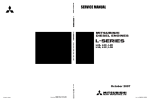
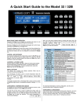
1. External view
1.1 Model S3Q2
Fuel injection nozzle
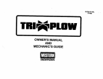
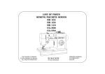
Oil filler
Glow plug
Inlet manifold
Water pump
Water drain plug
Fuel injection pump
Front
Rear
Stop solenoid
Fuel feed pump
Flywheel
Oil pan
Left side of engine
Hanger
Hanger
Thermostat
Thermo unit
Exhaust manifold
Alternator
Rear
Front
Oil level gauge
Oil cooler
Crankshaft pulley
Oil pressure switch
Starter
Oil drain plug
Right side of engine
1-2
GENERAL
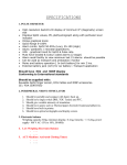
1.2 Model S3Q2-T
Fuel injection nozzle
Oil filler
Glow plug
Inlet manifold
Water pump
Water drain plug
Fuel injection pump
Front
Rear
Stop solenoid
Fuel feed pump
Flywheel
Oil pan
Left side of engine
Turbocharger
Hanger
Hanger
Thermostat
Thermo unit
Exhaust manifold
Oil level gauge
Alternator
Oil separator
Rear
Front
Oil cooler
Oil pressure switch
Crankshaft pulley
Starter
Oil drain plug
Right side of engine
1-3
GENERAL
2. System flow diagrams
2.1 Fuel system - flow diagram
Fuel leak off pipe
Fuel injection nozzle
Fuel return pipe
To fuel tank
Fuel injection pump
From fuel tank
Fuel feed pump
Fuel system - flow diagram
2.2 Lubrication system - flow diagram
Turbocharger
(S3Q2-T)
Valve mechanism
Push rod
Valve
Tappet
Piston
Relief valve
Camshaft
Oil main gallery
Timing gear
Oil pump
Oil strainer
Oil drain plug
Crankshaft
Oil filter
(With built-in bypass valve)
Lubrication system - flow diagram
1-4
GENERAL
2.3 Cooling system - flow diagram
Thermostat
Radiator
Bypass pipe
Water pump
Fan
Oil cooler
Cooling system - flow diagram
2.4 Inlet and exhaust system - flow diagram
Exhaust
Inlet
Turbocharger
(S3Q2-T)
Exhaust manifold
Inlet manifold
Inlet and exhaust system - flow diagram
1-5
GENERAL
3. Engine serial number location
The engine serial number is stamped on the side of the
crankcase.
Stamp location of engine serial number
1-6
GENERAL
4. Main specifications
This specifications may differ from your engine specifications.
Table 1-1 Main specifications(1 / 3)
Engine type
S3Q2
S3Q2-T
Vertical type, Water-cooled,
4-stroke cycle diesel engine
Model
Number and arrangement of cylinders
3 cylinder in-line
Combustion type
Swirl chamber type
Valve mechanism
Overhead
Cylinder bore × stroke
88 × 103 mm [3.46 × 4.06 in.]
Displacement
1.879 L [0.5 U.S.gal.]
Compression ratio
Main
specifications
22 : 1
JIS K2204, Diesel oil or its equivalent
(ASTM D975, etc.).
Fuel used
Firing order
1-3-2
Direction of rotation
Dimensions
Counterclockwise when viewed from flywheel
Overall length
608 mm [23.94 in.]
608mm [23.94 in.]
Overall width
492 mm [19.37 in.]
540mm [21.26 in.]
Overall height
633 mm [24.92 in.]
696 mm [27.40 in.]
Approx. 160 kg
[352.7 lb]
Approx. 165 kg
[363.8 lb]
Dry weight
Cylinder
Type
Piston ring
Number of rings
Dry (integral with cylinder block)
Compression rings: 2
Oil ring (w/expander): 1
Open
BTDC 30°
Close
ABDC 50°
Open
BBDC 74°
Close
ATDC 30°
Inlet valve
Basic engine
Valve timing
(when warm)
Exhaust valve
Starting system
Electric
Starting aid system
Glow plug
Type
In-line (Bosch A type)
Fuel injection pump
Fuel feed pump
Plunger diameter
ø 6.5 mm [0.26 in.]
Type
Bosch, piston type
Speed control system
Centrifugal type
Type
Bosch RSV type
Governor
Fuel system
Nozzle type
Number of spray holes
Fuel injection nozzle
Spray hole diameter
Spray angle
Valve opening pressure
Bosch, Throttle type
1
ø 1.0 mm [0.04 in.]
0°
13.73 MPa {140 kgf/cm²} [1991 psi]
1-7
GENERAL
Table 1-1 Main specifications(2 / 3)
Engine type
S3Q2
S3Q2-T
Forced circulation type
(pressure feed by oil pump)
Lubricating method
Standard
(API service classification)
Class CF or CH-4
Engine oil
Engine oil capacity
Engine total: approx. 6.4 L [1.69 U.S.gal.]
(approx. 5.7 L [1.51 U.S.gal.] in oil pan)
Type
Lubrication
system
Oil pump
Discharge capacity
Relief valve
Valve opening pressure
Trochoid
10.45 L [2.76 U.S.gal.]/
min or more
(at pump rotation of
1000 min-1)
16.11 L [4.26 U.S.gal.]/
min or more
(at pump rotation of
1000 min-1)
0.30 to 0.40 MPa {3 to 4 kgf/cm²}
[42.67 to 56.89 psi]
Type
Water-cooled type
Oil cooler
Heating surface area
Cooling method
Water-cooled, forced circulation
Coolant capacity (engine)
3 L [0.79 U.S.gal.], approx.
Type
Fan belt
Fan
Volute type centrifugal pump
Discharge capacity
70 L/min
(Pump rotating speed 3000 min-1,
total pump head 2.5 × 10⁻²MPa)
Type
Raw edge plain silver belt type A
Type
Push type (PP fan)
Water pump
Cooling system
0.063 m² [97.65 in².]
No. of blades
7 equally spaced blades
Outside diameter
ø 382 mm [15.04 in.]
Type
Wax type
Thermostat
Inlet and
exhaust system
1-8
Valve opening temperature
76.5 ± 1.5°C [169.7 ± 2.7°F]
Type
-
TD03
Number of units
-
1
Turbocharger
GENERAL
Table 1-1 Main specifications(3 / 3)
Engine type
S3Q2
Manufacturer
Mitsubishi Electronic Corporation
Type
M008T70371
Pinion meshing type
Output
1
Ring gear and pinion ratio
Starter
Load
characteristic
Load
characteristics
10/113
Voltage
11 V
Current
130 A or below
Speed
Electrical system
Pinion shift
12 V - 2.0 kW
Qty
No-load
characteristics
S3Q2-T
3600 r/min or more
Voltage
7.7 V
Current
400 A
Torque
10.59 N·m {1.08 kgf·m} [7.8 lbf·ft]
Speed
1280 r/min or more
Voltage
3V
Current
1000 A or below
Torque
29.42 N·m {3.0 kgf·m} [21.7 lbf·ft] or more
Manufacturer
Mitsubishi Electronic Corporation
Model number
A007T02077C
Alternator
Output
12 V - 50 A
Regulated voltage
14.7 ± 0.3 V
Type
Sheathe glow plug
Glow plug
Rated voltage
DC10.5 V
1-9
GENERAL
5. Tips on disassembling and reassembling
This service manual specifies the recommended procedures
to be followed when servicing Mitsubishi engines. The
manual also specifies the special tools that are required for
the work, and the basic safety precautions to follow when
working.
Note that this manual does not exhaustively cover potential
hazards that could occur during maintenance, inspection and
service work of engine.
When working on an engine, follow the relevant directions
given in this manual and observe the following instructions:
5.1 Disassembling
(1) Use correct tools and instruments. Serious injury or
damage to the engine will result from using the wrong
tools and instruments.
(2) Use an overhaul stand or work bench if necessary, and
follow the disassembling procedures described in this
manual.
(3) Keep the engine parts in order of removal to prevent
losing them.
(4) Pay attention to assembling marks. Put your marks on
the parts, if necessary, to ensure correct reassembling.
(5) Carefully check each part for defects during
disassembling or cleaning. Do not miss symptoms
which can not be detected after disassembling or
cleaning.
(6) When lifting or carrying heavy parts, exercise utmost
caution to ensure safety. Pay attention to balance of
heavy parts when handling. (Get help, and use jacks,
chain blocks and guide bolts as necessary.)
5.2 Reassembling
(1) Wash all engine parts, except such parts as oil seals, Orings and rubber sheets, in cleaning oil and dry them
with compressed air.
(2) Use correct tools and instruments.
(3) Use only high-quality lubricating oils and greases of
appropriate types. Be sure to apply oil, grease or
adhesive to the part wherever specified.
(4) Use a torque wrench to tighten parts correctly when
their tightening torques are specified.
Refer to "Tightening torque table."
(5) Replace all gaskets and packings with new ones unless
specified otherwise. Apply adhesive if necessary. Use
only the proper amount of adhesive.
1-10
SERVICE DATA
1. Maintenance service data ...............2-2
1.1
1.2
1.3
1.4
1.5
1.6
General .................................................... 2-2
Basic engine ............................................ 2-2
Fuel system.............................................. 2-7
Lubrication system ................................... 2-7
Cooling system ........................................ 2-7
Electrical system ...................................... 2-8
2. Tightening torque table ...................2-9
2.1 Major bolt tightening torque ..................... 2-9
2.1.1 Basic engine...............................................2-9
2.1.2 Fuel system ................................................2-9
2.1.3 Lubrication system ...................................2-10
2.1.4 Cooling system.........................................2-10
2.1.5 Electrical system ......................................2-10
2.1.6 Inlet and exhaust systems........................2-10
2.2 Standard bolt and nut tightening torque. 2-11
2-1
SERVICE DATA
1. Maintenance service data
1.1 General
Table 2-1 Maintenance service data table - General
Inspection point
Nominal
Maximum rotation speed
(rated rotation speed used as reference)
Standard
Limit
Unit: mm [in.]
Remark
Varies depending on the specifications
Adjust governor setting.
Minimum rotation speed
2.55 MPa
{26 kgf/cm²}
[370 psi]
2.94 MPa
{30 kgf/cm²}
[427 psi]
Compression pressure
(at 750 min-1)
0.1 MPa
{1 kgf/cm²}
[14 psi] or more
0.05 MPa
{0.5 kgf/cm²}
[7 psi]
(at 1500 min-1)
0.29 to 0.49 MPa
{3 to 5 kgf/cm²}
[43 to 71 psi]
0.15 MPa
{1.5 kgf/cm²}
[21 psi]
Engine oil
pressure
Open
BTDC 30°
Close
ABDC 50°
Open
BBDC 74°
Close
ATDC 30 °
When oil and water temperatures
at 20 to 30°C [68 to 86°F]
(150 to 200 min-1) or more
When oil temperature is
70 to 90°C [158 to 194°F].
Inlet valve
Valve timing
± 3°
(Crank angle)
Exhaust valve
Valve clearance (when cold)
0.25 [0.0098]
Fuel injection timing
Both inlet and exhaust
Varies depending on the specifications
Fan belt deflection
(crankshaft pulley to alternator pulley)
Amount of deflection when
pressed with the thumb firmly.
(98 N {10 kgf} [72 lbf])
Applox. 13 [0.51]
1.2 Basic engine
Table 2-2 Maintenance service data table - Basic engine (1 / 5)
Inspection point
Rocker
Nominal
Standard
Rocker arm inside diameter
ø 19
[0.75]
19.01 to 19.03
[0.7484 to 0.7492]
Rocker shaft outside diameter
ø 19
[0.75]
18.98 to 19.00
[0.7472 to 0.7480]
Clearance between rocker arm and shaft
Clearance between
valve stem and
guide
0.07
[0.0028]
ø8
[0.31]
7.940 to 7.955
[0.3126 to 0.3132]
7.900
[0.3110]
Exhaust
ø8
[0.31]
7.920 to 7.940
[0.3118 to 0.3126]
7.850
[0.3091]
Inlet
0.045 to 0.075
[0.0018 to 0.0030]
0.130
[0.0051]
Exhaust
0.060 to 0.095
[0.0024 to 0.0037]
0.150
[0.0059]
Height to top of valve guide
2-2
0.01 to 0.05
[0.0004 to 0.0020]
Inlet
Valve stem
outside diameter
Valve and
valve guide
Limit
15.5
[0.610]
15.1 to 15.6
[0.594 to 0.614]
Unit: mm [in.]
Remark
SERVICE DATA
Table 2-2 Maintenance service data table - Basic engine (2 / 5)
Valve seat
Inspection point
Nominal
Valve seat angle
30°
0.8
[0.031]
0.7 to 0.9
[0.028 to 0.035]
1.3
[0.051]
Seat width
1.18
[0.0465]
1.04 to 1.32
[0.0409 to 0.0520]
1.6
[0.063]
Refacing
permissible up to
1.2 [0.047]
1.7
[0.067]
Free length
Perpendicularity
Set length/set load
Push rod
Limit
Valve sinkage
Valve margin
Valve
spring
Standard
48.85
[1.9232]
47.60
[1.8740]
θ = 1.5°
Δ = 1.3 [0.051]
Lf = 48.85
[1.9232]
Δ = 1.5 [0.059]
at the end
43 mm [1.69 in.]/
176 to 196 N
{18 to 20 kgf}
[130 to 145 lbf]
43 mm [1.69 in.]/
147 N
{15 kgf}
[108 lbf]
Runout
0.3
[0.012] or less
Distortion of bottom face
0.05
[0.0020] or less
Unit: mm [in.]
Remark
Seat width
Valve
Valve sinkage
seat angle
Valve
margin
ǰ
ٌ
Lf
Runout (dial gaule reading)
when pushrod is supported
along
center line of spherical surface at
either end.
0.20
[0.0079]
Reface minimum thickness.
Cylinder head
1.3
[0.0512]
1.27 to 1.37
[0.0500 to 0.0539]
STD
87.970
[3.4634]
87.955 to 87.985
[3.4628 to 3.4640]
87.770
[3.4555]
0.25
[-0.0098] OS
88.220
[3.4732]
88.205 to 88.235
[3.4726 to 3.4738]
88.020
[3.4653]
0.50
[-0.0197] OS
88.470
[3.4831]
88.455 to 88.485
[3.4825 to 3.4837]
88.270
[3.4752]
Compressed thickness of gasket
Outside diameter
Piston
Protrusion from crankcase
Weight difference in one engine
Clearance between
piston ring and ring
groove
Piston ring
0.13 to 0.60
[0.0051 to 0.0236]
14 [0.55] upper from the
bottom
right angle to the piston pin.
Bearing clearance check.
5 g [0.20 oz.] or
less
No.1 compression ring
0.060 to 0.100
[0.0024 to 0.0039]
0.200
[0.0079]
No.2 compression ring
0.045 to 0.080
[0.0018 to 0.0031]
0.150
[0.0059]
Oil ring
0.025 to 0.065
[0.0010 to 0.0026]
0.150
[0.0059]
No.1, 2 compression rings
0.25 to 0.40
[0.0098 to 0.0157]
1.50
[0.0591]
Oil ring
0.30 to 0.50
[0.0118 to 0.0197]
1.50
[0.0591]
Use the piston with replacing
the piston rings until reaching
the limits.
when reaching the limits,
replace the piston.
Closed gap of ring
2-3
SERVICE DATA
Table 2-2 Maintenance service data table - Basic engine (3 / 5)
Inspection point
Nominal
Standard
Piston pin hole inside diameter
ø 28
[1.10]
28.000 to 28.010
[1.1024 to 1.1028]
Outside diameter
ø 28
[1.10]
27.994 to 28.000
[1.1021 to 1.1024]
Limit
Remark
0.050
[0.0020]
Use the piston with replacing the piston pin until
reaching the limits.
when reaching the limits,
replace the piston.
0.080
[0.0031]
Replace the piston and
bushing
(Ream if necessary)
0.030 to 0.095
[0.0012 to 0.0037]
0.200
[0.0079]
Use connecting rod with
replacing bearing until
reaching the limit.
when exceeding the limit,
re-gring the crankpin and
replace the bearing with
under size.
0.05/100
[0.0020/3.94]
or less
0.15/100
[0.0059/3.94]
0.15 to 0.35
[0.0059 to 0.0138]
0.50
[0.0197]
Replace connecting rod.
Piston pin
Clearance between piston pin hole and
piston pin
Bushing inside diameter
0.000 to 0.016
[0.0000 to 0.0006]
ø 28
[1.10]
28.020 to 28.045
[1.1031 to 1.1041]
0.020 to 0.051
[0.0008 to 0.0020]
Clearance between piston pin
Clearance between crankpin and connecting rod bearing (oil clearance)
Connecting rod
Bend and twist
End play
Connecting rod bearing inside diameter
Exhaust manifold
Distortion of manifold
ø 58
[2.28]
Unit: mm [in.]
58.000 to 58.045
[2.2835 to 2.2852]
0.15
[0.0059] or less
Clearance between shaft and bushing
0.025 to 0.075
[0.0010 to 0.0030]
0.100
[0.0039]
Replace bushing.
End play
0.05 to 0.20
[0.0020 to 0.0079]
0.35
[0.0138]
Replace thrust plate.
Crankshaft gear to idler gear
0.03 to 0.16
[0.0012 to 0.0063]
0.25
[0.0098]
Idler gear to camshaft gear
0.04 to 0.17
[0.0016 to 0.0067]
0.25
[0.0098]
Idler gear to fuel injection pump gear
0.03 to 0.18
[0.0012 to 0.0071]
0.25
[0.0098]
Idler gear
Timing gear
backlash
2-4
Replace gear.
SERVICE DATA
Table 2-2 Maintenance service data table - Basic engine (4 / 5)
Inspection point
Inlet
Nominal
Standard
Limit
Major axis
Major axis minor axis =
6.684 [0.2631]
Major axis minor axis =
6.184 [0.2435]
Major axis minor axis =
7.344 [0.2891]
Major axis minor axis =
6.844 [0.2694]
0.04 [0.0016]
or less
0.10
[0.0039]
46.916
[1.8471
Cam lift
(D1 - D2)
+0.1
-0.3
+0.004
-0.012
]
Major axis
Exhaust
45.944
[1.8088
+0.1
-0.3
+0.004
-0.012
Runout
]
No.1,
No.2
ø 54
[2.13]
53.94 to 53.96
[2.1236 to 2.1244]
53.90
[2.1220]
No.3
ø 53
[2.09]
52.94 to 52.96
[2.0842 to 2.0850]
52.90
[2.0827]
Unit: mm [in.]
Remark
D2
D1
Repaor the runout,
or replace.
Journal outside diameter
Circularity of journal
0.02
[0.0008] or less
Cylindericity of journal
0.02
[0.0008] or less
Camshaft
Clearance between camshaft journal
outside diameter and crankcase hole
inside diameter.
Camshaft hole inside diameter
0.07 to 0.11
[0.0028 to 0.0043]
No.1,
No.2
ø 54
[2.13]
54.03 to 54.05
[2.1272 to 2.1279]
No.3
ø 53
[2.09]
53.03 to 53.05
[2.0878 to 2.0886]
Circularity of camshaft hole
0.02
[0.0008] or less
Camshaft hole coaxiality
0.05
[0.0020] or less
0.15
[0.0059]
End play
5
[0.20]
0.10 to 0.25
[0.0039 to 0.0098]
0.30
[0.0118]
Tappet hole inside diameter
ø 14
[0.55]
14.000 to 14.018
[0.5512 to 0.5519]
14.100
[0.5551]
0.016 to 0.052
[0.0006 to 0.0020]
0.080
[0.0031]
Replace thrust plate.
Tappet
Clearance between crankcase
2-5
SERVICE DATA
Table 2-2 Maintenance service data table - Basic engine (5 / 5)
Inspection point
Nominal
Standard
Crankpin outside diameter
ø 58
[2.28]
57.950 to 57.970
[2.2815 to 2.2823]
Crankpin journal outside diameter
ø 65
[2.56]
64.965 to 64.985
[2.5577 to 2.5585]
Distance between centers of journal and
crankpin
51.5
[2.028]
51.46 to 51.54
[2.0260 to 2.0291]
Roundness of journals and crankpins
0.01
[0.0004] or less
0.03
[0.0012]
Cylindericity of journals and crankpins
0.01
[0.0004] or less
0.03
[0.0012]
Fillet radius of pin
R3
[0.12]
±0.2
[0.008]
Fillet radius of journals
R3
[0.12]
±0.2
[0.008]
Runout (TIR)
End play
Inside diameter
Crankcase hole
(main bearing
lower hole)
Main bearing
ø 69
[2.72]
0.100 to 0.204
[0.0039 to 0.0080]
0.300
[0.0118]
0.05
[0.0020] or less
0.035 to 0.085
[0.0014 to 0.0033]
23
[0.91]
88
[3.46]
88.000 to 88.035
[3.4646 to 3.4659]
0.25
[-0.0098] OS
88.25
[3.4744]
88.250 to 88.285
[3.4744 to 3.4758]
0.50
[-0.0197] OS
88.50
[3.4842]
88.500 to 88.535
[3.4842 to 3.4856]
Cylindricality of cylinder inside
diameter
TIR
When main bearing cap is
tightened.
0.200
[0.0079]
22.979 to 23.000
[0.9047 to 0.9055]
0.05
[0.0020] or less
STD
Remark
69.000 to 69.019
[2.7165 to 2.7173]
Coaxiality
Flatness of top surface
2-6
0.10
[0.0039]
0.02
[0.0008] or less
Thrust bearing width (cap width)
Cylinder inside
diameter
0.04
[0.0016] or less
Circularity
Clearance between main bearing and
crankshaft journal (oil clearance)
Crankcase
Limit
Pin maximum
defection:
0.01 [0.0004]
or less
Parallelism between journal and crankpin
Crankshaft
Unit: mm [in.]
0.015
[0.0006] or less
0.20
[0.0079]
Standard value
+0.2 [+0.008]
Reface minimum thickness.
SERVICE DATA
1.3 Fuel system
Table 2-3 Maintenance service data table - Fuel system
Inspection point
Valve opening pressure
Fuel
injection
nozzle
Nominal
Standard
13.73 MPa
{140 kgf/cm²}
[1991 psi]
13.93 to 14.71 MPa
{142 to 150 kgf/cm²}
[2020 to 2133 psi]
Spray cone angle
Nozzle valve seat oil
sealing
Limit
Remark
Standard is a value of new parts.
Check nozzle with a hand tester (at fuel oil
temperature 20°C [68°F]). Replace the nozzle tip if the spray pattern is still bad after
washing in clean fuel oil.
0°
Seat shall hold a test pressure lower than
valve opening pressure by 1.96 MPa
{20 kgf/cm²} [285 psi] for 10 seconds.
Wash in clean fuel oil or replace nozzle tip.
1.4 Lubrication system
Table 2-4 Maintenance service data table - Lubrication system
Inspection point
Oil pump
Nominal
Standard
Limit
Rotor, case and end play
0.04 to 0.09
[0.0016 to 0.0035]
0.15
[0.0059]
Clearance between outer rotor and inner
rotor
0.13 to 0.15
[0.0051 to 0.0059]
0.20
[0.0079]
Clearance between outer rotor and case
0.20 to 0.28
[0.0079 to 0.0110]
0.50
[0.0197]
ø 13
[0.51]
Shaft outside diameter
Valve opening pressure
Remark
12.985 to 13.000
[0.5112 to 0.5118]
0.032 to 0.074
[0.0013 to 0.0029]
Clearance between shaft and case
Relief valve
Unit: mm [in.]
0.34 MPa
{3.5 kgf/cm²}
[49.78 psi]
0.3 to 0.4 MPa
{3 to 4 kgf/cm²}
[42.67 to 56.89 psi]
1.5 Cooling system
Table 2-5 Maintenance service data table - Cooling system
Inspection point
Water pump
Nominal
Interference thread between case
and bearing unit
Temperature at which valve starts
opening
Standard
Limit
Unit: mm [in.]
Remark
0.017 to 0.064
[0.0007 to 0.0025]
76.5°C
[170°F]
75 to 78°C
[167 to 172°F]
Thermostat
Temperature at which valve lift is
8 [0.32], minimum
90°C
[194°F]
2-7
SERVICE DATA
1.6 Electrical system
Table 2-6 Maintenance service data table - Electrical system
Inspection point
Diameter
Commutator
Nominal
ø 32
[1.26]
31 N
{3.2 kgf}
[23.1 lbf]
18
[0.709]
11
[0.43]
26.7 to 36.1 N
{2.7 to 3.7 kgf}
[20 to 27 lbf]
14.7 N
{1.5 kgf}
[11 lbf]
Pinion gap
0.5 to 2.0
[0.020 to 0.079]
Armature current (A)
3600 or more
Brush leight
Spring ring outside diameter
When the tip of the pinion is fixed at 2mm
[0.08in.] away from stop
position,voltage is 8V or
less.
130 or less
Rotational speed
(min-1)
Resistance between slip rings
0
[0.00] lower limit
11
Brush spring tension
2-8
0.2
[0.008]
0.5
[0.020] or lower
Voltage (V)
Alternator
0.4 to 0.6
[0.0157 to 0.0236]
Pinion shaft
thrust gap
No-load characteristics
Remark
0.10
[0.004]
Brush leight
Tension of brush springs
Limit
31.4
[1.236]
Runout
Mica depth
Starter
Standard
Unit: mm [in.]
2.8 Ω
4.8 to 6.0 N
{0.5 to 0.6 kgf}
[3.6 to 4.3 lbf]
2.2 N
{0.2 kgf}
[1.4 lbf]
18.5
[0.728]
5.0
[0.197]
2.6 to 3.0 Ω
ø 22.7
[0.894]
at 20°C [68°F]
22.1
[0.870]
SERVICE DATA
2. Tightening torque table
2.1 Major bolt tightening torque
2.1.1 Basic engine
Table 2-7 Tightening torque table - Basic engine
Threads
Dia × Pitch
(mm)
N·m
kgf·m
lbf·ft
Cylinder head bolt
12 × 1.75
118 ± 5
12 ± 0.5
87 ± 3.6
Cylinder head plug
16 × 1.5
44 ± 5
4.5 ± 0.5
33 ± 3.6
Rocker cover
8 × 1.25
12 ± 1
1.2 ± 0.1
9 ± 0.7
Adjusting screw nut
8 × 1.25
20 ± 2
2 ± 0.2
14 ± 1.4
Rocker shaft bracket (short)
8 × 1.25
11.3 ± 1.5
1.15 ± 0.15
8 ± 1.1
Rocker shaft bracket (long)
8 × 1.25
15 ± 2
1.5 ± 0.2
11 ± 1.4
Main bearing cap
12 × 1.75
83 ± 5
8.5 ± 0.5
61 ± 3.6
Connecting rod cap
10 × 1.0
54 ± 5
5.5 ± 0.5
40 ± 3.6
Flywheel
12 × 1.25
83 ± 5
8.5 ± 0.5
61 ± 3.6
Camshaft thrust plate
8 × 1.25
12 ± 1
1.2 ± 0.1
9 ± 0.7
Front plate
8 × 1.25
12 ± 1
1.2 ± 0.1
9 ± 0.7
Timing gear case cover
8 × 1.25
12 ± 1
1.2 ± 0.1
9 ± 0.7
Crankshaft pulley
24 × 1.5
392 ± 10
40 ± 1
289 ± 7.2
Flywheel housing
10 × 1.25
60 ± 6
6.1 ± 0.6
44 ± 4.3
Rear plate stud
10 × 1.25
24 ± 2
2.4 ± 0.2
17 ± 1.4
Description
2.1.2
Torque
Remark
Fuel system
Table 2-8 Tightening torque table - Fuel system
Threads
Dia × Pitch
(mm)
N·m
kgf·m
lbf·ft
Fuel injection nozzle
20 × 1.5
59 ± 6
6 ± 0.6
43 ± 4.3
Fuel injection nozzle
retaining nut
16 × 0.75
36.8 ± 2.45
3.75 ± 0.25
27 ± 1.8
Fuel leak off pipe mounting nut
12 × 1.5
23 ± 2
2.3 ± 0.2
17 ± 1.4
Fuel injection pump gear
12 × 1.75
64 ± 5
6.5 ± 0.5
47 ± 3.6
Fuel injection pipe nut
12 × 1.5
29 ± 3
3 ± 0.3
22 ± 2.2
Fuel return pipe nut
10 × 1.25
20 ± 2
2 ± 0.2
14 ± 1.4
Fuel injection pump fuel eye bolt
14 × 1.5
17 ± 2
1.75 ± 0.2
13 ± 1.4
Fuel injection pump overflow valve
12 × 1.5
17 ± 2
1.75 ± 0.2
13 ± 1.4
Fuel injection pump lubrication pipe
(flare)
12 × 1.0
19 ± 3
1.95 ± 0.3
14 ± 2.2
R1/8
25 ± 2
2.5 ± 0.2
18 ± 1.4
Fuel injection pump lubrication eye bolt
10 × 1.0
10 ± 2.5
1.05 ± 0.2
8 ± 1.8
Separate oil filter connector
20 × 1.5
29 ± 5
3 ± 0.5
22 ± 3.6
Description
Fuel injection pump lubrication connector
Torque
Remark
2-9
SERVICE DATA
2.1.3
Lubrication system
Table 2-9 Tightening torque table - Lubrication system
Threads
Dia × Pitch
(mm)
N·m
kgf·m
lbf·ft
Oil pan
8 × 1.25
8±1
0.8 ± 0.1
6 ± 0.7
Oil pan drain plug
14 × 1.5
39 ± 5
4 ± 0.5
29 ± 3.6
Oil cooler connector
20 × 1.5
69 ± 10
7±1
51 ± 7.2
Oil relief valve
22 × 1.5
49 ± 5
5 ± 0.5
36 ± 3.6
Oil pump set bolt
12 × 1.75
34 ± 4
3.5 ± 0.4
25 ± 2.9
Oil pressure switch
PT 1/8
29.4
3.0
22
Oil relief valve plug
18 × 1.5
44 ± 5
4.5 ± 0.5
33 ± 3.6
Description
2.1.4
Torque
Remark
Cooling system
Table 2-10 Tightening torque table - Cooling system
Description
Torque
1/4 - 18
NPTF
Water drain plug
2.1.5
Threads
Dia × Pitch
(mm)
N·m
kgf·m
lbf·ft
39 ± 4
4 ± 0.4
29 ± 2.9
Remark
Electrical system
Table 2-11 Tightening torque table - Electrical system
Threads
Dia × Pitch
(mm)
N·m
kgf·m
lbf·ft
10 × 1.25
18 ± 2
1.8 ± 0.2
13 ± 1.4
Glow plug (terminal)
4 × 0.7
1.3 ± 0.2
0.13 ± 0.02
0.9 ± 0.1
Starter terminal B
8 × 1.25
11 ± 1
1.1 ± 0.1
8 ± 0.7
Starter terminal S
5 × 0.8
3.3 ± 0.8
0.34 ± 0.08
2.5 ± 0.6
Description
Glow plug (Engine body)
2.1.6
Torque
Remark
Inlet and exhaust systems
Table 2-12 Tightening torque table - Inlet and exhaust systems
Threads
Dia × Pitch
(mm)
N·m
Exhaust manifold
8 × 1.25
Inlet hose clamp
-
Description
Torque
Remark
kgf·m
lbf·ft
30 ± 3
3.1 ± 0.3
22 ± 2.2
7±1
0.7 ± 0.1
5 ± 0.7
-
6±1
0.6 ± 0.1
4 ± 0.7
Length of the 23 mm [0.90 in.]
-
7±1
0.7 ± 0.1
5 ± 0.7
Length of the 33 mm [1.30 in.]
Turbo air hose board clamp
2-10
SERVICE DATA
2.2 Standard bolt and nut tightening torque
Table 2-13 Standard bolt and nut tightening torque
Description
Threads
Dia × Pitch
(mm)
Width
across flats
(mm) [in.]
Strength classification
7T
10.9
7
Metric automobile screw thread
Metric course screw thread
10
N·m
kgf·m
lbf·ft
N·m
kgf·m
lbf·ft
M8 × 1.25
12 [0.47]
17
1.7
13
30
3.1
22
M10 × 1.25
14 [0.55]
33
3.4
24
60
6.1
44
M12 × 1.25
17 [0.67]
60
6.1
44
108
11.0
80
M14 × 1.5
22 [0.87]
97
9.9
72
176
17.9
130
M16 × 1.5
24 [0.94]
145
14.8
107
262
26.7
193
M18 × 1.5
27 [1.06]
210
21.4
155
378
38.5
279
M20 × 1.5
30 [1.18]
291
29.7
215
524
53.4
386
M22 × 1.5
32 [1.26]
385
39.3
284
694
70.8
512
M24 × 1.5
36 [1.42]
487
49.7
359
878
89.5
648
M27 × 1.5
41 [1.61]
738
75.3
544
1328
135.5
979
N·m
kgf·m
lbf·ft
N·m
kgf·m
lbf·ft
M10 × 1.5
14 [0.55]
32
3.3
24
58
5.9
43
M12 × 1.75
17 [0.67]
57
5.8
42
102
10.4
75
M14 × 2
22 [0.87]
93
9.5
69
167
17.0
123
M16 × 2
24 [0.94]
139
14.2
103
251
25.6
185
M18 × 2.5
27 [1.06]
194
19.8
143
350
35.7
258
M20 × 2.5
30 [1.18]
272
27.7
201
489
49.9
361
M22 × 2.5
32 [1.26]
363
37.0
268
653
66.6
482
M24 × 3
36 [1.42]
468
47.7
345
843
86.0
622
M27 × 3
41 [1.61]
686
70.0
506
1236
126.0
912
Note: (a) This table lists the tightening torque for standard bolts and nuts.
(b) The numerical values in the table are for fasteners with spring washers.
(c) The table shows the standard values with a maximum tolerance value of ±10%.
(d) Use the tightening torque in this table unless otherwise specified.
(e) Do not apply oil to threaded portions. (Dry)
2-11
SERVICE TOOLS
1. General tools...................................3-2
2. Special tool......................................3-3
3-1
SERVICE TOOLS
1. General tools
1
2
5
3
6
9
4
7
8
10
General tools
Table 3-1 General tool list
No.
Tool name
Part No.
Use
-
Tool set
32A91-00010
1
Tool bag
34491-01102
2
Spanner
F9600-10012
Width across flats: 10 × 12 mm [0.39 × 0.47 in.]
3
Spanner
F9600-14017
Width across flats: 14 × 17 mm [0.55 × 0.67 in.]
4
Spanner
F9600-22024
Width across flats: 22 × 24 mm [0.87 × 0.94 in.]
5
Wrench
F9612-12014
Width across flats: 12 × 14 mm [0.47 × 0.55 in.]
6
Screw driver
91267-00201
(+), (-)
7
Socket
F9614-17000
Width across flats: 17 mm [0.67 in.]
8
Socket
F9614-19000
Width across flats: 19 mm [0.75 in.]
9
Handle
F9618-25000
10
Extension bar
F9615-15000
3-2
Includes parts No.1 through 10
SERVICE TOOLS
2. Special tool
Table 3-2 Special tool list (1 / 3)
Tool name
Part No.
Shape
Use
Compression gauge
33391-02100
Engine compression pressure
measuring
0 to 7 MPa {0 to 71.4 kgf/cm²}
[0 to 1015.54 psi]
Gauge adapter
30691-21100
Engine compression pressure
measuring
Turnine handle
30691-21800
Engine turning
Valve spring pusher
30691-04500
Valve spring removal/installation
Valve guide remover
32A91-00300
Valve guide removal
Valve sheet insert caulking
tool
Stem seal installer
Inlet: 30691-02700
Exhaust:
30691-02800
32C91-10400
Valve seat installation
Stem seal installation
3-3
SERVICE TOOLS
Table 3-2 Special tool list (2 / 3)
Tool name
Part No.
Shape
Use
Socket
34491-00300
Camshaft,thrust plate and rocker
bracket installation
Valve guide installer
32C91-00300
Valve guide installation
Idler bushing installer
30691-51900
Idler bushing removal/installation
Idler bushing puller
MH061077
Idler shaft removal
Piston ring pliers
31391-12900
Piston ring removal/installation
Oil seal sleeve installer guide
set
30691-13010
Oil seal sleeve installation of
crankshaft rear side
Piston guide
30691-58100
Piston installation
3-4
SERVICE TOOLS
Table 3-2 Special tool list (3 / 3)
Tool name
Front oil seal installer
Part No.
32C91-00500
Shape
Use
Front oil seal installation
3-5
DETERMINATION OF OVERHAUL
1. Determining overhaul timing ...........4-2
2. Testing compression pressure ........4-3
4-1
DETERMINATION OF OVERHAUL
1. Determining overhaul timing
In most cases, the engine should be overhauled when the compression pressure of the engine becomes low. An increase in
engine oil consumption and blow-by gas are also considered to evaluate the engine condition. Besides, such symptoms as a
decrease in output, increase in fuel consumption, decrease in oil pressure, difficulty of engine starting and increase in noise are
also considered for judging the overhaul timing, although those symptoms are often affected by other causes, and are not
always effective to judge the overhaul timing. Decreased compression pressure shows a variety of symptoms and engine
conditions, thus making it difficult to accurately determine when the engine needs an overhaul. The following shows typical
problems caused by reduced compression pressure.
(1)
(2)
(3)
(4)
Decreased output power
Increased fuel consumption
Increased engine oil consumption
Increased blow-by gas through the breather due to worn cylinder liners and piston rings (Visually check the blow-by
amount)
(5) Increased gas leakage due to poor seating of inlet and exhaust valves
(6) Difficulty in starting
(7) Increased noise from engine parts
(8) Abnormal exhaust color after warm-up operation
The engine can exhibit these conditions in various combinations. Some of these problems are directly caused by worn engine
parts, while others are not. Phenomena described in items (2) and (6) will result from improper fuel injection volume, fuel
injection timing, worn plunger, faulty nozzles and also faulty conditions of electrical devices such as battery and starter. The
most valid reason to overhaul an engine is a decrease in compression pressure due to worn cylinder liners and pistons, as
described in item (4). In addition to this item, it is reasonable to take other problems into consideration for making the total
judgement.
4-2
DETERMINATION OF OVERHAUL
2. Testing compression pressure
&$87,21
(a) Be sure to measure the compression pressure for
all the cylinders. It is not a good practice to measure the compression pressure for only one cylinder, and presume the compression for the
remaining cylinder.
(b) Also be sure to check engine speed when measuring the compression pressure, as compression
pressure varies with engine speed.
(c) Measuring the compression pressure at regular intervals is important to obtain correct data.
(d) On the new engine or overhauled engine, the
compression pressure rises temporary due to
breaking-in condition of the piston rings and the
valve seats. But it drops later due to the wear of
these parts.
Gauge adapter
P/N:30691-21100
Compression
gauge
P/N:33391-02100
Testing compression pressure
(1) Remove the glow plugs from all cylinders.
(2) Attach the compression gauge adapter to the cylinder,
and connect compression gauge.
(3) Crank the engine with the starter, then read the
compression gauge indication while the engine is
running at the specified speed.
(4) If the compression pressure is lower than the limit,
overhaul the engine.
Item
Compression pressure
Standard
Limit
2.94 MPa
{30 kgf/cm²}
[427 psi]
2.55 MPa
{26 kgf/cm²}
[370 psi]
Note: (a) Measure the compression pressure with the
engine running at 150 to 200 min-1.
(b) Measure the compression pressure with the oil
and coolant temperature at 20 to 30°C [68 to
86°F].
4-3
DISASSEMBLY OF BASIC ENGINE
1. Disassembling and inspecting cylinder
head and valve mechanism ............5-2
1.1
1.2
1.3
1.4
1.5
1.6
1.7
Removing rocker shaft assembly............. 5-3
Disassembling rocker shaft assembly...... 5-3
Removing cylinder head assembly .......... 5-3
Removing valve and valve spring ............ 5-4
Removing valve stem seal ....................... 5-4
Cleaning cylinder head bottom surface.... 5-4
Measuring piston protrusion..................... 5-5
2. Disassembling and inspecting
flywheel ...........................................5-6
2.1 Removing flywheel................................... 5-7
2.2 Removing oil seal case ............................ 5-7
2.3 Removing rear plate................................. 5-7
3. Disassembling and inspecting timing
gear, camshaft and oil pan..............5-8
3.1
3.2
3.3
3.4
3.5
3.6
3.7
3.8
3.9
3.10
3.11
Removing crankshaft pulley..................... 5-9
Removing timing gear case ..................... 5-9
Measuring timing gear backlash .............. 5-9
Measuring idler gear end play................ 5-10
Removing idler gear............................... 5-10
Measuring camshaft end play ................ 5-10
Inverting crankcase................................ 5-10
Removing oil pan and oil pan gasket ..... 5-11
Removing oil pump ................................ 5-11
Removing camshaft ............................... 5-11
Removing front plate.............................. 5-11
4. Disassembling and inspecting piston,
connecting rod, crankshaft and
crankcase......................................5-12
4.1
4.2
4.3
4.4
4.5
4.6
4.7
4.8
4.9
4.10
4.11
Laying crankcase on its side.................. 5-13
Measuring connecting rod end play ....... 5-13
Removing connecting rod cap ............... 5-13
Removing carbon deposits from the upper
part of cylinder ....................................... 5-14
Pulling out piston.................................... 5-14
Removing piston ring ............................. 5-14
Removing piston pin .............................. 5-14
Uprearing crankcase.............................. 5-15
Measuring crankshaft end play .............. 5-15
Removing main bearing cap .................. 5-15
Removing crankshaft ............................. 5-16
5-1
DISASSEMBLY OF BASIC ENGINE
1. Disassembling and inspecting cylinder head and valve mechanism
10
4
1
3
9
8
2
Replace
7
5
14
15
19
Damaged threads,
worn rod contact surface
Worn valve cap contact surface,
clogged oil holes, worn bushings
16
6
Wear, clogged oil holes
Fatigue, damage
11
12
Wear at both ends, deflection
13
Wear
20
Crack, carbon deposits,
water scale adhesion
Replace
17
18
Uneven wear
Uneven wear on stems and faces,
damage, fatigue
Disassembling and inspecting cylinder head and valve mechanism
Disassembling sequence
1 Rocker cover
8 Rocket shaft bracket
15 Valve retainer
2 Adjusting screw
9 Rocket shaft spring
16 Valve spring
3 Bolt (short)
10 Rocket shaft
17 Inlet valve
4 Bolt (long)
11 Push rod
18 Exhaust valve
5 Valve cap
12 Cylinder head bolt
19 Valve stem seal
6 Snap ring
13 Cylinder head
20 Cylinder head gasket
7 Rocker arm
14 Valve cotter
5-2
DISASSEMBLY OF BASIC ENGINE
1.1 Removing rocker shaft assembly
&$87,21
Always loosen shorter bolts first. Failing to do so may
cause the damage to the rocker shaft bracket.
(1) Loosen the rocker arm adjusting screws by rotating
about one turn.
(2) Loosen the shorter rocker bracket bolts first.
(3) Then, loosen the longer rocker bracket bolts.
(4) Remove the rokcer bracket bolts, and remove the
rocker shaft assembly from the cylinder head.
(5) Remove push rods.
Removing rocker shaft assembly
1.2 Disassembling rocker shaft assembly
Disassemble the rocker shaft assembly.
Note: Be sure to arrange the parts in order during
disassembly. Keep the original combination of rocker
arm and shaft assembly, and when reassembling,
make sure to install them in their original positions to
restore the same clearance between the rocker shaft
and arms.
Do not remove the rocker bushing unless it is
defective or its inside diameter exceeds the limit.
Disassembling rocker shaft assembly
1.3 Removing cylinder head assembly
&$87,21
When removing the cylinder head gasket, be careful
not to damage the cylinder head or crankcase surface
by tools such as a screwdriver.
(1) Remove the cylinder head bolt.
(2) Remove the cylinder head assembly by lifting it up.
Note: If the cylinder head assembly cannot be removed due
to crimping of the cylinder head gasket, tap the thick
area on the side of the cylinder head using a plastic
hammer to give a shock.
(3) Remove the gasket from the cylinder head.
Note: If there is a cylinder head problem, check the bolts for
tightness with a torque wrench before removing the
cylinder head bolts.
Removing cylinder head assembly
5-3
DISASSEMBLY OF BASIC ENGINE
1.4 Removing valve and valve spring
Using a valve spring pusher, compress the valve spring
evenly and remove the valve cotters.
Note: If valves are reusable, mark each valve seat and the
mating valve guide for identifying their original
positions. Do not mix valve seats with other valve
guides.
Valve spring pusher
P/N:30691-04500
Removing valve and valve spring
1.5 Removing valve stem seal
Grab the stem seal with pliers and remove.
Note: Be sure to replace the stem seal with the new one
when reassembling the valve and valve spring.
Removing valve stem seal
1.6 Cleaning cylinder head bottom surface
Taking care not to damage the cylinder head bottom surface,
remove residue of old gasket.
Note: First, roughly scrape off residue of old gasket using a
scraper. Then, grind off the remaining residue using
an engine-oil immersed oil stone.
Cleaning cylinder head bottom surface
5-4
DISASSEMBLY OF BASIC ENGINE
1.7 Measuring piston protrusion
&$87,21
Piston protrusion must always meet the standard, as
the amount of protrusion not only influences on the
engine performance, but also it is important to prevent
valve interference.
Measure the protrusion of each piston following the
instructions below. If the measured value exceeds the limit,
inspect and repair each bearings.
(1) Search the top dead center of the piston by using dial
guage.
(2) Apply the dial gauge plunger to the top surface of the
crankcase, and zero the dial gauge.
(3) Measure the protrusion at three points on the piston
head, and calculate the mean value. Subtract the mean
value from the thickness of the gasket compressed by
tightening the cylinder head, and the clearance between
the piston top and cylinder head will be determined.
Item
Measuring piston protrusion
Standard
Piston protrusion
0.13 to 0.60 mm
[0.0051 to 0.0236 in.]
Compressed thickness of
cylinder head gasket
1.27 to 1.37 mm
[0.0500 to 0.0539 in.]
5-5
DISASSEMBLY OF BASIC ENGINE
2. Disassembling and inspecting flywheel
5
Replace
4
Crack, abnormality of knock hole
2
Replace
3
Steaks on wear surface,
stepped wear, cracks,
ring gear damage,
abnormal wear
1
Disassembling and inspecting flywheel
Disassembling sequence
1 Flywheel
3 Oil seal
2 Oil seal case
4 Rear plate
5-6
5 Gasket
DISASSEMBLY OF BASIC ENGINE
2.1 Removing flywheel
&$87,21
(a) Be careful not to cut yourself with the ring gear
when pulling out the flywheel.
Be careful not to drop or hit the flywheel when
removing.
(b) The personnel who holds the pulley must pay due
attention to safety.
Also, personnel must stay in close contact with
each other during work.
(1) One personnel must firmly hold the pulley with a
wrench to prevent the flywheel from turning.
(2) Remove one bolt from the flywheel.
(3) Screw a guide bolt into the threaded hole of the bolt that
has been removed.
(4) Remove remaining bolts from the flywheel.
(5) Hold the flywheel firmly with both hands, and by
moving it back and forth, pull it out straight.
Note: The ring gear is shrink fitted to the flywheel. Do not
remove the ring gear unless it is defective.
Removing flywheel
2.2 Removing oil seal case
&$87,21
Be very careful not to damage the oil seal.
(1) Remove bolts from the oil seal case.
(2) Pry out the oil seal case from the cylinder block using a
screwdriver.
Removing oil seal case
2.3 Removing rear plate
&$87,21
Be very careful not to damage the oil seal.
Remove the rear plate mounting bolts, and remove the rear
plate.
Removiing rear plate
5-7
DISASSEMBLY OF BASIC ENGINE
3. Disassembling and inspecting timing gear, camshaft and oil pan
Replace
9
8
Damage, wear
Flaking, uneven contact, damage,
abnormal key groove condition
Crack, abnormality
of knock hole
7
3
Clogged oil
holes, Wear
5
Wear
4
Replace
Replace
1
6
2
Worn belt groove,
worn oil seal
contact surface
Disassembling and inspecting timing gear, camshaft and oil pan
Disassembling sequence
1 Crankshaft pulley
4 Baffle plate
7 Oil pump
2 Cover
5 Idler gear
8 Camshaft
3 Timing gear case
6 Oil pan
9 Front plate
5-8
DISASSEMBLY OF BASIC ENGINE
3.1 Removing crankshaft pulley
&$87,21
The bar that stops the the crankshaft from turning may
come off. Pay due attention to safety.
(1) Screw two guide bolts into the threaded holes at the rear
end of the crankshaft. Stick a bar across the guide bolts
to prevent the crankshaft from turning.
(2) Remove the crankshaft pulley.
(3) Take out the woodruff key of the crankshaft.
Bolt
(M12 × 1.25 mm)
Removing crankshaft pulley
3.2 Removing timing gear case
&$87,21
The front plate is bolted to the crankcase from inside
the gear case. Do not attempt to remove the front plate
together with the gear case by tapping.
(1) Remove bolts from the timing gear case.
(2) Remove the timing gear case.
Note: Bolts have different lengths. Pay attention to the
positions of bolts to ensure correct reassembling.
Removing timing gear case
3.3 Measuring timing gear backlash
Measure the backlash of the timing gears by using one of
the following two methods; measure the gear play with the
dial gauge plunger applied to a tooth flank on the pitch
circle at a right angle to the tooth axis, or measure the
clearance between gears by inserting a feeler gauge between
the gears at the tooth-to-tooth contacting area. Replace the
faulty gear pair if the limit is exceeded.
Item
Timing
gear
backlash
Standard
Between crankshaft
gear and idler gear
0.03 to 0.16 mm
[0.0012 to 0.0063 in.]
Between idler gear and
valve camshaft gear
0.04 to 0.17 mm
[0.0016 to 0.0067 in.]
Between idler gear and
pump camshaft gear
0.03 to 0.18 mm
[0.0012 to 0.0071 in.]
Limit
Measuring idler gear backlash
0.25 mm
[0.0098 in.]
5-9
DISASSEMBLY OF BASIC ENGINE
3.4 Measuring idler gear end play
Using a feeler gauge or dial gauge, measure the end play of
idler gear.
If the measured value exceeds the limit, replace the idler
gear with the new gear.
Item
End play
Standard
Limit
0.05 to 0.20 mm
[0.0020 to 0.0079 in.]
0.35 mm
[0.0138 in.]
Thrust plate
Measuring idler gear end play
3.5 Removing idler gear
(1) Remove the thrust plate bolt.
(2) Remove the idler gear while turning the gear.
Removing idler gear
3.6 Measuring camshaft end play
Measure the camshaft end play with the camshaft gear
attached. If the limit is exceeded, replace the thrust plate
with a new one.
Item
Camshaft end play
Standard
Limit
0.10 to 0.25 mm
[0.0039 to 0.0098 in.]
0.30 mm
[0.0118 in.]
Measuring camshaft end play
3.7 Inverting crankcase
&$87,21
Do not place the engine directly on the ground. It
causes cracking the oil pan.
(1) Attach the wire rope to the crankcase. Using a crane,
hoist the crankcase and lay it with its side faced
downwards.
(2) After that, hoist the crankcase again and invert it.
Oil pan
Inverting crankcase
5-10
DISASSEMBLY OF BASIC ENGINE
3.8 Removing oil pan and oil pan gasket
(1) Remove the bolts from the oil pan, and remove the oil
pan from crankcase.
(2) Remove the oil pan gasket from crankcase.
Removing oil pan and oil pan gasket
3.9 Removing oil pump
Remove the oil pump set bolts, and pull out the oil pump
from crankcase.
Oil pump set bolt
Removing oil pump
3.10 Removing camshaft
&$87,21
Be careful not to damage the cams of camshaft and
the bushings.
(1) Rotate the camshaft to see the thrust plate bolt through
the camshaft gear hole.
(2) By using the socket, remove the thrust plate bolt.
(3) Remove the camshaft from the crankcase.
(4) Remove the tappet.
Socket
P/N:34491-00300
Removing camshaft
3.11 Removing front plate
(1) Remove the front plate bolts.
(2) Remove the front plate from the crankcase.
Note: If it is difficult to remove the front plate, lightly tap it
with a plastic hammer.
Removing front plate
5-11
DISASSEMBLY OF BASIC ENGINE
4. Disassembling and inspecting piston, connecting rod, crankshaft and crankcase
12
13
Adhesion of water
scale, corrosion,
flaking
Wear, damage
Surface scratches, cracks,
damage, wear, carbon deposits
16
Fatigue
14
Wear
10
11
9
Wear, clogged oil holes
Cracks, clogged oil holes
Damaged threads
15
7
8
Wear
17
Serration for cracks, wear
1
5
6
2
Scratches,
cracks, dint,
clogged oil holes,
wear
Cracks
Flaking, uneven contact
4
Scratches on inside and outside surfaces,
corrosion, flaking, seizing
3
Damaged threads
Disassembling and inspecting piston, connecting rod, crankshaft and crankcase
Disassembling sequence
1 Connecting rod cap
7 Connecting rod
13 No.2 compression ring
2 Connecting rod bearing (lower)
8 Connecting rod bearing (upper)
14 Oil ring
3 Main bearing cap
9 Snap ring
15 Tappet
4 Main bearing cap (lower)
10 Piston pin
16 Crankcase
5 Crankshaft
11 Piston
17 Check valve
6 Main bearing (upper)
12 No.1 compression ring
Note: When replacing the crankcase, carefully remove parts (relief valve, etc.) mounted on the non-reusable crankcase so that
they can be reused.
5-12
DISASSEMBLY OF BASIC ENGINE
4.1 Laying crankcase on its side
Attach the wire rope to the crankcase. By using a crane,
hoist the crankcase and lay it with its side faced downwards.
Layin crankcase on its side
4.2 Measuring connecting rod end play
(1) Measure the clearance (end play) between the
connecting rod big-end and crankshaft by using the
thickness gauge.
(2) If it exceeds the limit, replace the connecting rod with
new one.
Item
Connecting rod end play
Standard
Limit
0.15 to 0.35 mm
[0.0059 to 0.0138 in.]
0.50 mm
[0.0197 in.]
Measuring connecting rod end play
4.3 Removing connecting rod cap
(1) Mark the cylinder number on the connecting rod and
connecting rod cap.
(2) Remove the connecting rod cap.
(3) Be sure to make the disassembled lower connecting rod
bearing easy to recognize its cylinder number, and
upper or lower.
Note: Be careful not to damage the bearings. Be sure to
arrange the disassembled bearings in the order for
correct assembly.
Removing connecting rod cap
5-13
DISASSEMBLY OF BASIC ENGINE
4.4 Removing carbon deposits from the upper
part of cylinder
&$87,21
Be sure to remove carbon deposits from the upper part
of the cylinder before removing the piston, as they
could cause damage to the piston and piston ring.
Remove carbon deposits from the upper part of cylinder
using a cloth or oil paper.
Note: Be careful not to damage the inner surface of the
cylinder.
Removing carbon deposit at the upper section of
cylinder
4.5 Pulling out piston
(1) Turn the crankshaft to bring the piston to the top dead
center.
(2) Using a piece of wood such a hammer handle, push the
mating surface of the connecting rod cap, and pull the
piston and connecting rod upward from the cylinder.
Pulling out piston
4.6 Removing piston ring
Remove the piston rings using piston ring pliers.
Piston ring pliers
P/N:31391-12900
Removing piston ring
4.7 Removing piston pin
(1) Using snap ring pliers, remove the snap ring.
(2) Remove the piston pin, and separate the piston from the
connecting rod.
Note: Heat the piston with a piston heater or in hot water if
the piston pin is stubborn.
Snap ring pliers
Removing piston pin
5-14
DISASSEMBLY OF BASIC ENGINE
4.8 Uprearing crankcase
Uprear the crankcase softly with its upper faced downward.
Positioning crankcase
4.9 Measuring crankshaft end play
(1) With attach the dial gauge to top of the crankshaft,
measure the end play.
(2) If measured value exceeds the limit, replace the flange
bearing with new one.
Item
Standard
Limit
Crankshaft end play
0.100 to 0.204 mm
[0.0039 to 0.0080 in.]
0.300 mm
[0.0118 in.]
Measuring crankshaft end play
4.10 Removing main bearing cap
&$87,21
When removing the main bearing cap, be careful to
not damage the lower main bearing lower that are
attached to the cap. Also be careful not to drop those
parts, which may damage the crankshaft.
(1) Unscrew the main bearing cap bolts.
(2) Unscrew the main bearing cap.
Note: Mark the bearings for their cylinder numbers.
Removing main bearing cap
5-15
DISASSEMBLY OF BASIC ENGINE
4.11 Removing crankshaft
&$87,21
Be careful not to damage bearings when removing the
crankshaft.
(1) Slowly lift the crankshaft straight up.
(2) Arrange the bearings in the order of disassembly so that
their original positions are restored when reassembling.
Note: (a) When raising the crankshaft, do not allow wire
chain to come into contact with the crankshaft.
To avoid damage to the crankshaft when raising,
use a cloth belt or pad.
(b) Mark the bearings for their cylinder numbers.
5-16
Removing crankshaft
INSPECTION AND REPAIR OF BASIC ENGINE
1. Inspecting and repairing cylinder head
and valve mechanism .....................6-2
1.1 Measuring distortion of the bottom surface of
the cylinder head...................................... 6-2
1.2 Measuring clearance between rocker arm and
rocker shaft .............................................. 6-2
1.3 Measuring perpendicularity and free length of
valve spring.............................................. 6-2
1.4 Measuring push rod runout ...................... 6-3
1.5 Measuring valve stem outside diameter and
valve guide inside diameter ..................... 6-3
1.6 Replacing valve guide.............................. 6-4
1.7 Inspecting valve face ............................... 6-5
1.8 Replacing valve seat................................ 6-6
1.9 Refacing valve face.................................. 6-6
1.10 Refacing valve seat.................................. 6-7
1.11 Lapping valve and valve seat................... 6-7
1.12 Removing combustion jet......................... 6-8
2. Inspecting and repairing flywheel ....6-9
2.1 Inspecting ring gear ................................. 6-9
2.2 Replacing ring gear.................................. 6-9
2.2.1 Removing ring gear ....................................6-9
2.2.2 Installing ring gear ......................................6-9
4.5 Measuring clearance between connecting rod
bushing and piston pin ........................... 6-14
4.6 Replacing connecting rod bushing ......... 6-15
4.7 Inspecting connecting rod bend and twist6-15
4.8 Inspecting oil clearance of connecting rod
bearing ................................................... 6-16
4.9 Inspecting oil clearance of main bearing 6-17
4.10 Inspecting oil seal contact surface ......... 6-18
4.10.1 Installing oil seal sleeve........................... 6-18
4.10.2 Removing oil seal sleeve......................... 6-18
4.11 Measuring crankshaft runout.................. 6-19
4.12 Removing crankshaft gear ..................... 6-19
4.13 Installing crankshaft gear ....................... 6-19
4.14 Measuring cylinder inside diameter........ 6-20
4.14.1 Reboring cylinder..................................... 6-20
4.15 Measuring crankcase top surface
distortion................................................. 6-21
4.16 Inspecting tappet.................................... 6-21
4.17 Measuring clearance between tappet and
tappet guide hole.................................... 6-21
4.18 Inspecting piston cooling nozzle ............ 6-22
3. Inspecting and repairing timing gear,
camshaft and oil pan .....................6-10
3.1 Inspecting V-pulley................................. 6-10
3.2 Inspecting oil seal contact surface ......... 6-10
3.3 Measuring clearance between idler bushing
and idler shaft ........................................ 6-10
3.4 Replacing idler bushing.......................... 6-10
3.5 Replacing idler shaft .............................. 6-11
3.6 Measuring cam lift.................................. 6-11
3.7 Measuring camshaft journal diameter and
journal bore diameter ............................. 6-11
3.8 Measuring camshaft runout ................... 6-12
3.9 Removing camshaft gear ....................... 6-12
3.10 Installing camshaft gear and thrust plate 6-12
4. Inspecting and repairing piston,
connecting rod, crankshaft and
crankcase......................................6-13
4.1
4.2
4.3
4.4
Measuring piston outside diameter ........ 6-13
Measuring piston ring groove................. 6-13
Measuring piston ring end gap............... 6-14
Measuring piston pin bore diameter and piston
pin outside diameter............................... 6-14
6-1
INSPECTION AND REPAIR OF BASIC ENGINE
1. Inspecting and repairing cylinder head and valve mechanism
1.1 Measuring distortion of the bottom surface
of the cylinder head
With a straight edge placed on the bottom face of the
cylinder head, measure the bottom face distortion using a
feeler gauge. If the measurement exceeds the limit, grind the
bottom face using a surface grinder.
Item
Bottom surface
distortion
Standard
Limit
0.05 mm
[0.0020 in.] or less
0.20 mm
[0.0079 in.]
Note: Do not grind the surfaces more than 0.2 mm [0.008
in.] in total (cylinder head bottom surface plus
crankcase top surface).
Measuring distortion of the bottom surface of the
cylinder head
1.2 Measuring clearance between rocker arm
and rocker shaft
Measure the inside diameter of the rocker arm and outside
diameter of the rocker shaft.
Replace the rocker arm or rocker shaft if the clearance
exceeds the limit.
Item
Nominal
Standard
Limit
Rocker arm
inside
diameter
ø 19 mm
[0.75 in.]
19.01 to 19.03 mm
[0.7484 to 0.7492 in.]
-
Rocker shaft
diameter
ø 19 mm
[0.75 in.]
18.98 to 19.00 mm
[0.7472 to 0.7480 in.]
-
-
0.01 to 0.05 mm
[0.0004 to 0.0020 in.]
0.07 mm
[0.0028 in.]
Clearance
between
rocker arm
and shaft
1.3 Measuring perpendicularity and free length
of valve spring
Measure the perpendicularity and free length of the valve
spring. If the limit is exceeded, replace the valve spring with
a new one.
Item
Standard
Limit
Free length
48.85 mm
[1.9232 in.]
47.60 mm
[1.8740 in.]
ǰ
Perpendicularity
ٌ
Lf
Set length/set
force
6-2
θ = 1.5° or less
Δ(gap) = 1.3 mm
[0.051 in.] or less
Lf = 48.85 mm
[1.9232 in.]
43 mm [1.69 in.]/
176 to 196 N
{18 to 20 kgf}
[130 to 145 lbf]
Δ = 1.5 mm
[0.059 in.]
over entire
length
43 mm
[1.69 in.]/
147 N
{15 kgf}
[108 lbf]
Measuring
directions
Measuring
points
Measuring rocker arm inside diameter and rocker shaft
outside diameter
Spring perpendicularity (gap)
Free length
Squareness and free length of spring
INSPECTION AND REPAIR OF BASIC ENGINE
1.4 Measuring push rod runout
Measure the runout of push rod. If the standard value is
exceeded, replace the push rod.
Item
Push rod
runout
Standard
Remark
Pushrod
0.3 mm
Total indicated reading
[0.012 in.] or less
(TIR)
1/2L
1/2L
L
Measuring push rod runout
1.5 Measuring valve stem outside diameter and
valve guide inside diameter
Remove the carbon deposits from valve and valve guide.
Measure the diameter at the top and bottom ends at right
angles to the outer and inner surfaces, since valve stems and
valve guides are more likely to wear at both ends.
If the outside diameter is less than the limit, or the clearance
exceeds the limit, replace either the valve or the valve guide
with a new one.
Item
Valve
stem
outside
diameter
Clearance
between
valve stem
and valve
guide
Nominal
Standard
Limit
Inlet
ø 8 mm
[0.31 in.]
7.940 to 7.955 mm
[0.3126 to 0.3132 in.]
7.900mm
[0.3110 in.]
Exhaust
ø 8 mm
[0.31 in.]
7.920 to 7.940 mm
[0.3118 to 0.3126 in.]
7.850 mm
[0.3091 in.]
Inlet
-
0.045 to 0.075 mm
[0.0018 to 0.0030 in.]
0.130 mm
[0.0051 in.]
Exhaust
-
0.060 to 0.095 mm
[0.0024 to 0.0037 in.]
0.150 mm
[0.0059 in.]
15.5 mm
[0.610 in.]
15.1 to 15.6 mm
[0.594 to 0.614 in.]
-
Valve guide mounting dimension
Measuring
directions
Measuring
points
Measuring valve stem outside diameter
Inside micrometer
Measuring
locations
Measuring valve guide inside diameter
6-3
INSPECTION AND REPAIR OF BASIC ENGINE
1.6 Replacing valve guide
&$87,21
Because valve guides must be inserted to the specified amount, be sure to use a valve guide installer.
Valve guide remover
P/N:32A91-00300
(1) To remove valve guides, use a valve guide remover.
Valve guide
Pulling out valve guide
Press
Valve guide installer
P/N:32C91-00300
Valve guide
Press fitting valve guide
6-4
15.5 mm
[0.610 in.]
(2) To press-fit valve guides, use a valve guide installer.
(3) Check contacts between valves and valve seats after
replacing valve guides.
INSPECTION AND REPAIR OF BASIC ENGINE
1.7 Inspecting valve face
Apply a thin coat of Shinmyoutan or equivalent lead-free
coloring paste on the valve face, and strike the valve face
against the valve seat using a valve lapper to check for
contact condition. If the contact is not even, or any defects
are found, or if the limit is exceeded, reface or replace the
valve.
Note: (a) Inspect the valve face after the valve guide is
repaired or replaced.
(b) Do not rotate the valve when pressing the valve
face coated with Shinmyoutan or equivalent leadfree dye against the valve seat.
(c) Always lap the valve and valve seat after the
valve has been refaced or replaced.
Item
Nominal
Standard
Limit
30°
-
-
Valve
sinkage
0.8 mm
[0.031 in.]
0.7 to 0.9 mm
[0.028 to 0.035 in.]
1.3 mm
[0.051 in.]
Seat
width
1.18 mm
[0.0465 in.]
1.04 to 1.32 mm
[0.0409 to 0.0520 in.]
1.6 mm
[0.063 in.]
-
Refacing permissible up to
1.2 mm
[0.047 in.]
Valve
seat angle
Valve
seat
Valve margin
1.7 mm
[0.067 in.]
Valve lapper
Shinmyoutan
Checking valve face
Good
Bad
Valve-to-valve seat contact
Seat width
Valve margin
Valve seat
angle
Valve sinkage
Valve-to-valve seat contact position
6-5
INSPECTION AND REPAIR OF BASIC ENGINE
1.8 Replacing valve seat
(1) To remove the valve seat, weld a stud to the valve seat
as illustrated. Then, insert a rod into the valve guide
hole from the top of the cylinder head, and press out the
valve seat with the rod.
Note: Be careful not to allow spatters to adhere to the
machined surface of the cylinder head during
welding.
Weld
Shaft
Valve seat
Stud
8.8 ± 0.1
[0.346 ± 0.0039]
2.8 ± 0.1
[0.110 ± 0.0039]
8.8 ± 0.1
[0.346 ± 0.0039]
45°
2.8 ± 0.1
[0.110 ± 0.0039]
Removing valve seat using valve seat puller
(2) Before inserting a new valve seat, measure the cylinder
head bore diameter to make sure the interference meets
the specified value.
ø41 +0.02
0
[1.61 +0.008
]
0
ø33 +0.02
0
[1.30 +0.008
]
0
Inlet
Exhaust
45°
Unit: mm [in.]
Valve seat fitting bore
(3) Cool the valve seat for four minutes or more in liquid
nitrogen (at approximately -170°C [-274°F]) before
fitting it into the cylinder head, while keeping the
cylinder head at room temperature. Or heat the cylinder
head to 80 to 100°C [176 to 212°F] and cool the valve
seat sufficiently in ether or alcohol mixed with dry ice
before fitting it into the hot cylinder head.
(4) Fit the cold valve seat into the cylinder head using a
insert caulking tool.
Insert caulking tool
(Inlet) P/N:30691-02700, (Exhaust) P/N:30691-02800
Driving in valve seat
1.9 Refacing valve face
If the valve face is significantly worn out, reface the valve
face using a valve refacer.
Note: (a) Grind the valve face using the valve refacer at the
specified angle.
(b) Secure the valve margin width equal to or greater
than the limit. If the dimensions after refacing
does not meet the specified values, replace the
valve with a new one.
Valve refacer
Set the valve face
angle at the specified
angle.
Refacing valve face
6-6
INSPECTION AND REPAIR OF BASIC ENGINE
1.10 Refacing valve seat
(1) Use the valve seat cutter or valve seat grinder to reface
the valve seat. After refacing, sand the valve seat lightly
using 400 grit sandpaper, inserting it between the cutter
and valve seat.
(2) Lap the valve in the valve seat.
Note: (a) Valve seat refacing should be kept to an absolute
minimum.
(b) If the valve seat width exceeds the limit due to
wear or refacing, replace the valve seat with a
new one.
(c) If the valve sinkage exceeds the limit after
refacing, replace the valve seat with a new one.
1.11 Lapping valve and valve seat
Always lap the valve against the valve seat after refacing the
valve seat or after replacing the valve.
(1) Apply a thin coat of lapping compound evenly to the
valve face.
Note: (a) Do not allow the compound to adhere on the
valve stem.
(b) Compound spreads more evenly if it is mixed
with a small amount of engine oil.
(c) Use medium-grain compound (120 to 150 mesh)
for initial lapping, then use fine-grain compound
(200 mesh or finer) for finishing.
(2) Use a valve lapper for lapping. Strike the valve against
the valve seat while rotating the valve little by little.
(3) Wash off the compound using diesel fuel.
(4) Coat the contact surface of the valve with engine oil,
then lap the valve again.
(5) Check valve-to-seat contact.
Refacing valve seat
Lapping valve and valve seat
6-7
INSPECTION AND REPAIR OF BASIC ENGINE
1.12 Removing combustion jet
Replace the combustion jet only when it has defect as crack.
(1) Insert a round bar (approx; ø6 mm [0.24 in.]) into glow
plug hole, and tap the combustion jet inner face
perimeter lightly to pull out the combustion jet.
Round rod
(ø6 mm [0.24 in.])
Combustion jet
Removing combustion jet
(2) When installing the combustion jet, align the
positioning hole and jet nozzle with the center of
cylinder, press fit with tapping by plastic hammer.
Positioning hole
Combustion jet
15°
Jet nozzle
Center of
cylinder
Press-fitting combustion jet
6-8
INSPECTION AND REPAIR OF BASIC ENGINE
2. Inspecting and repairing flywheel
2.1 Inspecting ring gear
Inspect the ring gear for a missing tooth or worn teeth, and
if defects are found, replace the ring gear.
2.2 Replacing ring gear
2.2.1 Removing ring gear
(1) Heat the ring gear evenly using an acetylene torch or
other appropriate heat source.
(2) With a rod placed on the periphery of ring gear, tap the
rod with a hammer evenly around the ring gear, and
remove the ring gear.
2.2.2
Installing ring gear
Ring gear
Flywheel
Removing ring gear
(1) Heat the ring gear evenly up to approx. 150°C [176°F]
with an appropriate heater.
(2) Install the ring gear onto the flywheel with the no-gearchamfering side faced to the flywheel.
Note: Do not heat the ring gear excessively.
6-9
INSPECTION AND REPAIR OF BASIC ENGINE
3. Inspecting and repairing timing gear, camshaft and oil pan
3.1 Inspecting V-pulley
Check the V-belt groove of the pulley for wear. Attach a
new V-belt around a worn pulley, apply a high tension to the
belt, and check whether the top surface of the belt is outside
or inside of the pulley groove to determine the degree of
pulley groove wear.
When the top surface of V-belt is outside the pulley groove,
and the degree of wear is almost the same for every groove
(when pulley has two belt grooves or more), the remaining
service life of the pulley can be considered sufficient.
If the wear appears excessive, and the belt top surface sinks
1.6 mm or more down from the top edge of groove, the
pulley is not reusable. Replace the pulley with a new one.
1.6 mm [0.06 in.]
or more
Inspecting V-belt groove wear
3.2 Inspecting oil seal contact surface
Inspect the oil seal contact surface of the pulley. If the
pulley waers due to oil seal, replace the pulley with new
one.
3.3 Measuring clearance between idler bushing and idler shaft
Measure the inside diameter of the idler bushing and outside
diameter of the idler shaft. Replace the bushing if the
clearance exceeds the limit.
Item
Clearance between idler
bushing and idler shaft
Standard
Limit
0.025 to 0.075 mm
[0.0010 to 0.0030 in.]
0.100 mm
[0.0039 in.]
Measuring directions
Measuring
points
Measuring idler bushing inside diameter and idler shaft
diameter
3.4 Replacing idler bushing
(1) Use the idler bushing puller to replace idler bushing.
(2) To install the bushing, drive it from the boss side so that
it is flush with the gear boss face.
(3) After installing the bushing, measure the bushing inside
diameter, and if the inside diameter exceeds the
standard, ream the bushing.
Idler bushing puller
P/N:30691-51900
Removing
Installing
Replacing idler bushing
6-10
INSPECTION AND REPAIR OF BASIC ENGINE
3.5 Replacing idler shaft
To remove the idler shaft, use the idler shaft puller.
Note: When installing the idler shaft into the crankcase,
orient the idler shaft so that its oil hole faces the upper
crankcase.
Idler shaft puller
P/N:MH061077
Replacing idler shaft
3.6 Measuring cam lift
Measure the minor and major axes of cam to determine cam
lobe lift. If the lift is less than the limit, replace the camshaft
with a new one.
Item
Nominal
Major axis
Inlet
46.916
+0.1
-0.3
[1.8471
Cam
lift
mm
+0.004
-0.012
in.]
Major axis
Exhaust
45.944
+0.1
-0.3
[1.8088
mm
+0.004
-0.012
in.]
Standard
Limit
Major axis–
Minor axis
= 6.684 mm
[0.2631 in.]
Major axis–
Minor axis
= 6.184 mm
[0.2435 in.]
Major axis–
Minor axis
= 7.344 mm
[0.2891 in.]
Major axis–
Minor axis
= 6.844 mm
[0.2694 in.]
Measuring
locations
D1
D2
Measuring
directions
Measuring cam lift
3.7 Measuring camshaft journal diameter and
journal bore diameter
Measure the camshaft journal outside diameter and journal
bore diameter. If measured values exceeds the limit, replace
the camshaft with new one.
Measuring
locations
D1
D2
Item
Camshaft
journal
outside
diameter
Nominal
Standard
Limit
No.1, 2
ø 54 mm
[2.13 in.]
53.94 to 53.96 mm
[2.1236 to 2.1244 in.]
53.90 mm
[2.1220 in.]
No.3
ø 53 mm
[2.09 in.]
52.94 to 52.96 mm
[2.0842 to 2.0850 in.]
52.90 mm
[2.0827 in.]
-
0.07 to 0.11 mm
[0.0028 to 0.0043 in.]
0.15 mm
[0.0059 in.]
Clearance between
camshaft journal
outside diameter and
camshaft journal
inside diameter
Camshaft
journal
inside
diameter
Measuring
directions
Measuring camshaft journal diameter
Measuring
direction
No.1, 2
ø 54 mm
[2.13 in.]
54.03 to 54.05 mm
[2.1272 to 2.1279 in.]
-
No.3
ø 53 mm
[2.09 in.]
53.03 to 53.05 mm
[2.0878 to 2.0886 in.]
-
Measuring camshaft buhing inside diameter
6-11
INSPECTION AND REPAIR OF BASIC ENGINE
3.8 Measuring camshaft runout
Measure the camshaft runout using a dial gauge. If the limit
is exceeded, correct the camshaft using a press, or replace
the camshaft with a new one.
Note: With a dial gauge set on the camshaft, rotate the
camshaft one turn and read the gauge indication.
Item
Standard
Limit
Camshaft runout (TIR)
0.04 mm
[0.0016 in.] or less
0.10 mm
[0.0039 in.]
Measuring camshaft runout
3.9 Removing camshaft gear
Remove the camshaft gear by using a press.
Note: Remove the camshaft and thrust plate only when the
camshaft gear has defect.
Thrust plate
Removing camshaft gear
3.10 Installing camshaft gear and thrust plate
(1) Install the key and the thrust plate to the camshaft.
(2) Heat the camshaft to approximately 250°C [482°F] by
using gear heater.
(3) Press fit the camshaft gear by tapping.
Note: Do not forget to insert the thrust plate before
installing the camshaft gear.
Thrust plate
Camshaft gear
Installing camshaft gear and thrust plate
6-12
INSPECTION AND REPAIR OF BASIC ENGINE
4. Inspecting and repairing piston, connecting rod, crankshaft and crankcase
Item
Piston
outside
diameter
Nominal
Standard
Limit
STD
87.970 mm
[3.4634 in.]
87.955 to 87.985 mm
[3.4628 to 3.4640 in.]
87.770 mm
[3.4555 in.]
0.25 OS
88.220 mm
[3.4732 in.]
88.205 to 88.235 mm
[3.4726 to 3.4738 in.]
88.020 mm
[3.4653 in.]
0.50 OS
88.470 mm
[3.4831 in.]
88.455 to 88.485 mm
[3.4825 to 3.4837 in.]
88.270 mm
[3.4752 in.]
5g [0.20 oz.] or less
-
Weight difference per piston
The piston weight is stamped on the top of piston head.
14 mm [0.55 in.]
4.1 Measuring piston outside diameter
Using a micrometer, measure the piston outside diameter at
the skirt perpendicular to the piston pins as shown in the
illustration.
Direction at
right angles
to piston pin
Measuring piston outside diameter
Engine front
Identification
Front
mark B
mark
Engine front
Front
Identification
mark
mark T
Symbol
size
S3Q2
Piston
weight mark
S3Q2-T
Symbol
size
Piston
weight mark
Piston weight stamp location
4.2 Measuring piston ring groove
No.1 compression ring
&$87,21
Remove carbon deposits from pistons and check the
entire circumference of the piston.
(1) Remove deposits such as carbon from each ring groove.
(2) Check each ring groove for wear or damage. If it is
worn or damaged, replace the piston with a new one.
(3) Insert the piston ring into the piston ring groove. Apply
a straight edge and insert thickness gauges to measure
the clearance between ring and ring groove.
If the limit is exceeded, replace the piston ring with a
new one.
Item
Clearance
between
piston ring
and
ring groove
Standard
Limit
No.1
compression ring
0.060 to 0.100 mm
[0.0024 to 0.0039 in.]
0.200 mm
[0.0079 in.]
No.2
compression ring
0.045 to 0.080 mm
[0.0018 to 0.0031 in.]
0.150 mm
[0.0059 in.]
Oil ring
0.025 to 0.065 mm
[0.0010 to 0.0026 in.]
0.150 mm
[0.0059 in.]
No.2 compression ring
Measuring piston ring groove
6-13
INSPECTION AND REPAIR OF BASIC ENGINE
4.3 Measuring piston ring end gap
Place the piston rings in a gauge or a new cylinder liner, and
measure the gap of each ring with feeler gauges. If the limit
is exceeded, replace all the rings as a set.
Note: Using a piston, push the piston ring squarely into the
gauge or the cylinder liner.
Item
Piston ring
end gap
Standard
No.1, 2
compression ring
0.25 to 0.40 mm
[0.0098 to 0.0157 in.]
Oil ring
0.30 to 0.50 mm
[0.0118 to 0.0197 in.]
Sickness gauge
Limit
1.50 mm
[0.0591 in.]
Measuring piston ring end gap
4.4 Measuring piston pin bore diameter and
piston pin outside diameter
Measure the piston pin bore diameter and piston pin outside
diameter. Replace if the limit is exceeded.
Item
Nominal
Standard
Limit
Piston pin
inside diameter
ø 28 mm
[1.10 in.]
28.000 to 28.010 mm
[1.1024 to 1.1028 in.]
-
Piston pin
outside diameter
ø 28 mm
[1.10 in.]
27.994 to 28.000 mm
[1.1021 to 1.1024 in.]
-
-
0.000 to 0.016 mm
[0.000 to 0.0006 in.]
0.050 mm
[0.0020 in.]
Clearance between
piston pin bore
and piston pin
4.5 Measuring clearance between connecting
rod bushing and piston pin
Measure the inside diameter of the connecting rod bushing
and the outside diameter of the piston pin. Replace if the
limit is exceeded.
Item
Nominal
Standard
Limit
Bushing
inside diameter
ø 28 mm
[1.10 in.]
28.020 to 28.045 mm
[1.1031 to 1.1201 in.]
-
-
0.020 to 0.051 mm
[0.0008 to 0.0020 in.]
0.080 mm
[0.0031 in.]
Clearance
between
bushing and
piston pin
6-14
Measuring
locations
Measuring
directions
Measuring piston pin bore diameter and piston pin
outside diameter
Measuring
directions
Measuring
locations
Measuring connecting rod bushing inside diameter
INSPECTION AND REPAIR OF BASIC ENGINE
4.6 Replacing connecting rod bushing
Use a connecting rod bushing installer to replace the
connecting rod bushing.
(1) With the bushing joints oriented as shown in the
illustration, align the oil hole of bushing with the oil
hole of connecting rod, and press-fit the connecting rod
bushing into the connecting rod.
(2) After press-fitting, insert the piston pin, and make sure
the smooth movement of the connecting rod and piston
without looseness.
Match marks side
Oil hole
Bushing joint
Replacing connecting rod bushing
4.7 Inspecting connecting rod bend and twist
(1) Measure the dimensions of C and L in the illustration to
check bend and twist of the connecting rod. Straighten
the connecting rod with a press to meet the standard.
If the standard is exceeded after correction, replace the
connecting rod with a new one.
(2) In general, a connecting rod aligner is used to check
bend and twist.
Note: Before checking bend, tighten the connecting rod cap
to the specified torque.
(3) To inspect the connecting rod with the piston installed,
turn the piston upside down and place it on a surface
plate. Insert a round bar having the same diameter as
the crankpin into the big-end bore, and measure the
height of the bar using a dial gauge.
Item
Bend and twist of
connecting rod
Standard
Limit
0.05/100 mm
[0.0020/3.94 in.]
or less
0.15/100 mm
[0.0059/3.94 in.]
0.05
0.0020
[
]
100
3.94
C
L
0.05
0.0020
[
]
100
3.94
C
L
C
L
L
C
Piston
pin
Connecting rod bend
Connecting rod twist
Unit: mm [in.]
Inspecting connecting rod bend and twist
Using a connecting rod aligner to measure rod bend
and twist
D
C
A
B
Measuring bend of connecting rod
6-15
INSPECTION AND REPAIR OF BASIC ENGINE
4.8 Inspecting oil clearance of connecting rod
bearing
(1) Install the bearing to the connecting rod big end. After
tightening the connecting rod cap with the specified
torque, measure the inside diameter of the bearing.
Item
Nominal
Standard
Limit
connecting rod bearing
inside diameter
ø 58 mm
[2.28 in.]
58.000 to 58.045 mm
[2.2835 to 2.2852 in.]
-
Measuring
directions
Measuring
points
Tightening torque
54 ± 5 N·m
{5.5 ± 0.5 kgf·m}
[40 to 3.6 lbf·ft]
Measuring connecting rod bearing inside diameter
(2) Measure the crankpin outside diamter. Calculate the oil
clearance of connecting rod bearing by differential
between the bearing inside diamter and the crankshaft
pin outside diamter.
Item
Pin outside
diameter
(S.T.D)
Oil clearance
Nominal
Standard
Limit
ø 58 mm
[2.2835 in.]
57.950 to 57.970 mm
[2.2815 to 2.2823 in.]
-
-
0.030 to 0.095 mm
[0.0012 to 0.0037 in.]
0.200 mm
[0.0079 in.]
Measuring
directions
Measuring
points
Measuring crankpin diameter
(3) If the oil clearance exceed the limit, install the new
bearing and calculate the oil clearance again.
(4) Even so it exceeds the limit, use undersize bearings.
(0.25, 0.50, 0.75 U.S) If an undersize bearing is used,
grind the crankpin to the specified undersize refer to the
following chart.
Item
Crankpin
undersize
Undersize
Finished size
0.25 mm
[0.0098 in.]
ø 57.75 -0.050 mm
0.50 mm
[0.0197 in.]
0.75 mm
[0.0295 in.]
-0.030
R3 ± 0.2 mm or less
[0.12 ± 0.008 in.]
-0.0012
[2.2736 -0.0020 in.]
-0.030
ø 57.50 -0.050 mm
0.0012
[2.2638 --0.0020 in.]
-0.030
ø 57.25 -0.050 mm
-0.0012
[2.2539 -0.0020 in.]
&$87,21
(a) When grinding the crankshaft pin, be sure to grind
the all pin to same size.
(b) Finish the fillet R to R3±0.2 mm [R0.1181±0.0079
in.] or less.
6-16
Width of crankshaft thrust bearing surface
INSPECTION AND REPAIR OF BASIC ENGINE
4.9 Inspecting oil clearance of main bearing
(1) Install the main bearing and the main bearing cap to the
crankcase. After tightening the main bearing cap with
the specified torque, measure the bearing inside
diameter.
Tightening torque:
83 ± 5 N·m
{8.5 ± 0.5 kgf·m}
[61 ± 3.6 lbf·ft]
Measuring main bearing inside diameter
(2) Measure the crankshaft journal outside diameter.
Calculate the oil clearance of the main bearing by the
differential between the bearing inside diameter and the
journal outside diamter.
Item
Nominal
Standard
Limit
Journal
outside diameter
(S.T.D)
ø 65 mm
[2.56 in.]
64.965 to 64.985 mm
[2.5577 to 2.5585 in.]
-
-
0.035 to 0.085 mm
[0.0014 to 0.0033 in.]
0.200 mm
[0.0079 in.]
Oil clearance
Measuring Measuring
directions locations
Measuring crank journal outside diameter
(3) If the oil clearance exceed the limit, install the new
bearing and calculate the oil clearance again.
(4) Even so it exceeds the limit, use undersize bearings.
(0.25, 0.50, 0.75 U.S) If an undersize bearing is used,
grind the crankpin to the specified undersize refer to the
following chart.
Item
Crankpin
undersize
Undersize
Finished size
0.25 mm
[0.0098 in.]
ø 64.75 -0.035 mm
0.50 mm
[0.0197 in.]
0.75 mm
[0.0295 in.]
-0.015
R3 ± 0.2 mm or less
[0.12 ± 0.008 in.]
R3 ± 0.2 mm or less
[0.12 ± 0.008 in.]
-0.0006
[2.5492 -0.0014 in.]
-0.015
ø 64.50 -0.035 mm
-0.0006
[2.5394 -0.0014 in.]
-0.015
ø 64.25 -0.035 mm
-0.0006
[2.5295 -0.0014 in.]
&$87,21
(a) When grinding the crankshaft journal, be sure to
grind the all journals to same size.
(b) Finish the fillet R to R3±0.2 mm [R0.1181±0.0079
in.] or less.
Width of crankshaft thrust bearing surface
6-17
INSPECTION AND REPAIR OF BASIC ENGINE
4.10 Inspecting oil seal contact surface
Inspect the oil seal contact surface located on the crankshaft
rear part. If the crankshaft wears due to the oil seal, replace
the oil seal and the oil seal sleeve with new spare parts.
Oil seal
Oil seal sleeve
Installing front oil seal (1)
4.10.1 Installing oil seal sleeve
Oil seal sleeve
installer set
P/N:30691-13010
&$87,21
Be careful not to dent or wound the oil seal sleeve circumference.
When installing the oil seal sleeve, apply the oil to the
inside of the oil seal sleeve, and drive it into the crankshaft
by using oil seal sleeve installer set.
When the engine is operated again and the oil seal sleeve
wears, remove the oil seal sleeve by using following method
and replace the oil seal assembly (oil seal and oil seal
sleeve) with the new spare parts.
Guide
P/N:30691-13100
Installer
P/N:30691-13200
Installing oil seal sleeve
Oil seal
Oil seal sleeve
Installing front oil seal (2)
4.10.2 Removing oil seal sleeve
&$87,21
When making a cut in the sleeve, be very careful not to
damage the crankshaft with the chisel.
Make a cut at three locations on the periphery of the oil seal
sleeve to reduce its tension. To do so, hold a chisel against
the sleeve periphery in the radial direction and strike it with
a hammer. When the sleeve is loosened, remove the sleeve.
If the sleeve can not be removed by the above procedure,
hold the chisel against the sleeve in the axial direction and
tap on it lightly to make the sleeve expand. Once the
interference between the crankshaft and sleeve is
eliminated, the sleeve will be removed easily.
6-18
Removing oil seal sleeve
INSPECTION AND REPAIR OF BASIC ENGINE
4.11 Measuring crankshaft runout
Support the crankshaft at the front and rear journals with Vblocks, and measure the crankshaft runout at the center
journal using a dial gauge. If the runout deviates from the
standard only slightly, grind the crankshaft to repair. If the
runout exceeds the standard considerably, straighten the
crankshaft using a press.
If the limit is exceeded, replace the crankshaft.
If the crankshaft has been repaired by grinding or pressing,
inspect the crankshaft for cracks and other harmful damage
using a magnetic particle method.
Measuring crankshaft runout
Item
Standard
Limit
Remark
Crankshaft
runout
0.04 mm
[0.0016 in.] or less
0.10 mm
[0.0039 in.] or less
TIR
4.12 Removing crankshaft gear
Using a gear puller, remove the gear from the crankshaft.
Note: Do not strike the gear with a hammer.
Removing crankshaft gear
4.13 Installing crankshaft gear
(1) Install the key on the crankshaft.
(2) Press-fit the gear fully in alignment with the key.
Align them
Installing crankshaft gear
6-19
INSPECTION AND REPAIR OF BASIC ENGINE
4.14 Measuring cylinder inside diameter
Use a cylinder gauge to measure the inside diameter and
cylindericity of the cylinder at three locations in the A and B
directions as shown in the illustration.
If any one of the cylinders exceeds the repair limit, bore all
the cylinders and replace the pistons and piston rings with
oversize ones.
Piston and
piston ring size
Cylinder inside diameter
Size
mark
Standard
STD
88.000 to 88.035 mm
[3.4646 to 3.4659 in.]
0.25 mm O.S .
[0.0098 in.]
25
88.250 to 88.285 mm
[3.4744 to 3.4758 in.]
0.50 mm O.S.
[0.0197 in.]
50
88.500 to 88.535 mm
[3.4842 to 3.4856 in.]
Size
S.T.D
Cylindericity of cylinder
A
B
Measuring
directions
Measuring
points
Limit
Measuring cylinder inside diameter
0.015 mm
[0.0006 in.] or less
Standard
+0.2 mm
[0.008 in.]
-
&$87,21
(a) If the inside diameter of cylinder exceeds the limit,
replace the cylinder block.
(b) Bore the cylinders in the cylinder-number
sequence to prevent heat-induced distortion.
(1) Pistons are available in two sizes (0.25, 0.50 oversizes).
Select the piston size for all cylinders based on the
largest cylinder bore that has been measured.
(2) Measure the outside diameter of the piston that has
been selected.
The measuring position in the outside diameter is
shown in the illustration.
(3) Calculate the boring dimensions based on the piston
outside diameter that has been measured.
A: Piston outside diameter (mm)
(oversize piston that has been selected)
B: Clearance between piston and cylinder (standard)
0.03 mm [0.0012 in.]
C: Horning allowance 0.04 mm [0.0016 in.] or below
Boring dimension =A+B-C
(4) Bore each cylinder to dimension calculated above.
(5) Horn-finish each cylinder to achieve the final
dimension (the piston outside diameter plus the
clearance between the oversize piston and the cylinder
bore.)
6-20
14 mm [0.55 in.]
4.14.1 Reboring cylinder
Direction at
right angles
to piston pin
Measuring piston outside diameter
INSPECTION AND REPAIR OF BASIC ENGINE
4.15 Measuring crankcase top surface distortion
&$87,21
Refacing of cylinder head should be kept to an absolute minimum.
Excessive grinding of the cylinder head may result in
defects such as defective combustion and stamping
(contact between piston and valve).
Apply a straight edge to the top surface of the crankcase and
measure its distortion using a feeler gauge. If the distortion
exceeds the limit, grind the cylinder head using a surface
grinder.
Note: Do not overgrind the cylinder head, as the piston
protrusion deviates from the standard value.
Item
Distortion of crankcase
top surface
Standard
Limit
0.05 mm
[0.0020 in.] or less
0.20 mm
[0.0079 in.]
Measuring crankcase top surface distortion
Note: Do not grind the surfaces more than 0.2 mm
[0.008 in.] in total (cylinder head bottom surface plus
crankcase top surface).
4.16 Inspecting tappet
Inspect the cam contact surface of the tappets. Fit new
tappets if the surface is excessively worn or damaged.
Good
Bad
Bad
Contact surface of tappet and cam
4.17 Measuring clearance between tappet and
tappet guide hole
Measure clearance between the tappet and tappet hole.
Replace the tappet with a new one if the limit is exceeded.
Item
Nominal
Standard
Limit
Tappet hole
inside diameter
ø 14 mm
[0.55 in.]
14.000 to 14.018 mm
[0.5512 to 0.5519 in.]
14.100 mm
[0.5551 in.]
Clearance
between tappet
and tappet hole
-
0.016 to 0.052 mm
[0.0006 to 0.0020 in.]
0.080 mm
[0.0031 in.]
Measuring
direction
Measuring
direction
Measuring
points
Measuring
points
Measuring tappet outside diameter and crankcase
tappet bore inside diameter
6-21
INSPECTION AND REPAIR OF BASIC ENGINE
4.18 Inspecting piston cooling nozzle
Insert the round bar (ø4 mm [0.1575 in.] or less) to the top
of the piston cooling nozzle installed on the crankcase.
Inspect that the steal ball operates smoothly. If it does not
operated smoothly, replace the piston cooling nozzle with
new one.
Round rod
Inspecting piston cooling nozzle
6-22
REASSEMBLY OF BASIC ENGINE
1. Reassembling piston, connecting rod,
crankshaft and crankcase ..............7-2
1.1
1.2
1.3
1.4
1.5
1.6
1.7
1.8
1.9
1.10
1.11
1.12
1.13
1.14
Installing tappet........................................ 7-2
Installing main bearing ............................. 7-2
Installing crankshaft ................................. 7-2
Installing main bearing cap ...................... 7-3
Installing main bearing cap bolt ............... 7-3
Measuring crankshaft end play ................ 7-4
Reassembling piston and connecting rod 7-4
Installing piston ring ................................. 7-5
Preparation for installing pistons.............. 7-5
Installing connecting rod bolt and connecting
rod bearing............................................... 7-6
Installing Pistons ...................................... 7-6
Installing connecting rod cap ................... 7-7
Uprearing crankcase................................ 7-7
Inspecting crankshaft for rotation............. 7-7
2. Reassembling timing gear, camshaft
and oil pan.......................................7-8
2.1
2.2
2.3
2.4
2.5
2.6
2.7
Installing front plate.................................. 7-8
Installing camshaft ................................... 7-8
Installing oil pump .................................... 7-8
Installing oil pan ....................................... 7-9
Inverting crankcase.................................. 7-9
Installing front idler gear......................... 7-10
Inspecting and adjusting timing gear after
installation .............................................. 7-10
2.8 Installing oil seal..................................... 7-10
2.9 Installing timing gear case ..................... 7-11
2.10 Installing crankshaft pulley..................... 7-11
3. Reassembling flywheel .................7-12
3.1 Installing rear plate................................. 7-12
3.2 Installing oil seal case ............................ 7-12
3.3 Installing flywheel................................... 7-12
4. Reassembling cylinder head and valve
mechanism ....................................7-13
4.1
4.2
4.3
4.4
4.5
4.6
4.7
4.8
4.9
Installing valve stem seal ....................... 7-13
Installing valve and valve spring ............ 7-13
Installing cylinder head gasket............... 7-13
Installing cylinder head assembly .......... 7-14
Tightening cylinder head bolts ............... 7-14
Reassembling rocker shaft assembly .... 7-14
Inserting push rod .................................. 7-14
Installing rocker shaft assembly............. 7-15
Adjusting valve clearance ...................... 7-15
7-1
REASSEMBLY OF BASIC ENGINE
1. Reassembling piston, connecting rod, crankshaft and crankcase
1.1 Installing tappet
(1) Apply the engine oil to the tappet, and insert it to the
tappet hole on the crankcase.
(2) Make sure that the tappet rotates smoothly.
Apply engine oil
Installing tappet
1.2 Installing main bearing
(1) Install the main bearings (upper and lower) with
aligning lug groove of the crankcase and main bearing
cap.
Note: Install the bearing with groove to the crankcase, and
install the bearing without groove to the main bearing
cap.
(2) Install the flange main bearing to the rearmost
crankcase mating surface.
(3) Apply a small amount of engine oil to each bearing.
Bearing No.4
(with flange)
Apply engine oil.
Lug
groove
Installing main bearing
1.3 Installing crankshaft
(1) Wash the crankshaft thoroughly with cleaning oil and
dry it completely by compressed air.
Note: When washing the crankshaft, clean the inside of the
oil holes completely and make sure that no foreign
substances or dirt is present.
(2) Hold the crankshaft horizontally and slowly install it to
the crankcase.
(3) Apply a small quantity of engine oil to the crankshaft
journals.
Installing crankshaft
7-2
REASSEMBLY OF BASIC ENGINE
1.4 Installing main bearing cap
&$87,21
The foremost and rearmost caps should be installed
so that they are flush with the crankcase surface.
Install the main bearing caps so that their front marks
(arrow) and cap numbers are in numerical order from the
front of the engine.
Front mark
Engine
front side
5
1
2
3
Surfaces
must flush
Surfaces
must flush
Cap No.
Installing main bearing cap
1.5 Installing main bearing cap bolt
(1) Tighten the main bearing cap bolts alternately and
progressively to the specified torque.
(2) Make sure that the crankshaft rotates smoothly.
83 ± 5 N·m
{8.5 ± 0.5 kgf·m}
[61 ± 3.6 lbf·ft]
Installing main bearing cap bolt
Inspecting crankshaft for rotation
7-3
REASSEMBLY OF BASIC ENGINE
1.6 Measuring crankshaft end play
(1) Measure the crankshaft end play.
(2) If the measured end play is small, loosen the cap bolt
and retighten it.
(3) If the measured value exceeds the limit, replace the
flange bearing with new one.
Item
Standard
Limit
Crankshaft end play
0.100 to 0.204 mm
[0.0039 to 0.0080 in.]
0.300 mm
[0.0118 in.]
Measuring crankshaft end play
1.7 Reassembling piston and connecting rod
(1) Apply engine oil to the piston pin, and reassemble the
piston and the connecting rod by inserting the piston
pin, observing the orientation of piston and connecting
rod shown in the illustration.
Note: The pistons and piston pins are assembled to each
other in clearance fit. However, the piston pins are
more easily inserted into the pistons if the pistons are
warmed up with a heater or in hot water.
A
Piston mass
Alignment
marks
View A
Reassembling piston and connecting rod (1)
(2) Using ring pliers, install the snap ring. Check the snap
ring for its tension, and make sure the ring fits snugly in
the groove.
Note: Install all the snap rings so that their end gap faces
toward the bottom of the piston.
Ring pliers
Reassembling piston and connecting rod (2)
7-4
REASSEMBLY OF BASIC ENGINE
1.8 Installing piston ring
Top mark
&$87,21
No.1
compression
ring
Every piston ring has a top mark such as “R” near the
end gap. Install all piston rings with this mark facing
upward.
If the rings are installed upside down, it could cause
malfunctions such as excessive oil consumption or an
engine seizing.
No.2
compression
ring
No.1, No.2
Oil ring
(1) Install the piston rings to the piston with a ring
expander.
Piston and piston ring arrangement
(2) Install the oil ring with its end gap 180° away from the
joint of the coil spring, as shown in the illustration.
Coil spring butted ends
180°
Oil ring abutment
Installing oil ring and coil spring
1.9 Preparation for installing pistons
(1) Lay the engine along its side.
(2) Clean the cylinder sleeve inner surface and the crank
pin with a cloth, and apply engine oil.
Lay the crankcase on its side
Apply engine oil
Preparation for installing piston
7-5
REASSEMBLY OF BASIC ENGINE
1.10 Installing connecting rod bolt and connecting rod bearing
(1) Press fit the connecting rod bolts into the connecting
rod.
Note: When press fitting the bolt, make sure that the bolt
fully contacts its seating position without any
interference with the shoulder of mounting surface.
(2) Install the upper connecting rod bearing with its lug
fitted in the lug groove of connecting rod.
(3) Install the lower connecting rod bearing with its lug
fitted in the lug groove of connecting rod cap.
(4) Apply engine oil to the inner surface of bearing.
1.11 Installing Pistons
Lug groove
Installing connecting rod bearing
Camshaft side
Thrust position
No.1
Compression
ring end gap
&$87,21
Do not forcefully insert the piston, as it may cause
damage to the piston rings and crank pin.
(1) Apply engine oil to the circumference of the piston and
piston rings.
(2) Orient the ring end gaps diagonally opposite each other
avoiding the piston pin direction and its right angle
direction.
(3) Turn the crankshaft to bring the crank pin of the
cylinder to the top dead center.
(4) Using a piston guide, insert the piston from the top face
of crankcase into the cylinder sleeve.
Note: When installing the pistion, be sure to orient the
match mark on the connecting rod to the camshaft
side.
Piston pin
No.2
Compression
ring end gap
Combustion
chamber side
Oil ring end gap
Opposite-to-thrust
position
Installing piston (1)
Front mark
Piston guide
P/N:30691-58100
Installing piston (2)
Front mark
Front crankcase
Installing piston (3)
7-6
REASSEMBLY OF BASIC ENGINE
1.12 Installing connecting rod cap
(1) Fit the connecting rod bearing (lower) to the rod cap
with the lug aligned with the lug groove, and apply the
engine oil inside the bearing.
(2) Install the connecting rod cap to the connecting rod
(crankpin) with its match mark facing on the same side
as the match mark on the connecting rod.
(3) Tighten the connecting rod cap nuts by using hand.
(4) Tighten the connecting rod cap nuts evenly and
progressively to the specified torque.
(5) Inspect end play of the connecting rod. If end play is
small, loosen and retighten the cap nuts.
Lug groove
Installing connecting rod cap (1)
54 ± 5 N·m
{5.5 ± 0.5 kgf·m}
[40 ± 3.6 lbf·ft]
Matching mark
Installing connecting rod cap (2)
1.13 Uprearing crankcase
Uprear the crankcase softly with its upper faced downward.
Inverting crankcase
1.14 Inspecting crankshaft for rotation
Inspect that the crankshaft rotates smoothly.
Inspecting crankshaft for rotation
7-7
REASSEMBLY OF BASIC ENGINE
2. Reassembling timing gear, camshaft and oil pan
2.1 Installing front plate
(1) Clean the mounting surface of the gasket.
(2) According to need, apply the sealant to prevent the
gasket falling off.
(3) Apply the sealant (TheeBond 1211) to the mating
surface of the crankcase and main bearing cap, and
spread, the sealant evenly.
(4) With aligning to the dowel pin, install the gasket and
the front plate.
(5) Secure the front plate with mounting bolts.
Apply the sealant and
spread it evenly.
12 ± 1 N·m
{1.2 ± 0.1 kgf·m}
[9 ± 0.7 lbf·ft]
Installing front plate
2.2 Installing camshaft
&$87,21
Be careful not to damage camshaft journals, cams and
camshaft holes during insertion.
(1)
(2)
(3)
(4)
Apply engine oil to the camshaft journals and cams.
Slowly insert the camshaft assembly.
Tighten the thrust plate bolt to the specified torque.
Make sure that the camshaft rotates lightly. Move the
camshaft gear back and forth, and make sure there is
end play.
Apply engine oil.
Applying engine oil to camshaft
12 ± 1 N·m
{1.2 ± 0.1 kgf·m}
[9 ± 0.7 lbf·ft]
Socket
P/N:34491-00300
Installing camshaft
2.3 Installing oil pump
(1) Insert the oil pump to the oil pump hole on the
crankcase, then, make sure that the oil pump gear and
oil pump drive gear on the camshaft meshes correctly.
(2) From the crankcase side face, tighten the oil pump set
bolt with gasket to the specified torque.
Gasket
Oil pump
set bolt
34 ± 4 N·m
{3.5 ± 0.4 kgf·m}
[25.1 ± 2.9 lbf·ft]
Installing oil pump
7-8
REASSEMBLY OF BASIC ENGINE
2.4 Installing oil pan
Clean the both side of the oil pan gasket contact surfaces
and the contact surfaces of other parts thoroughly.
(1) Apply the sealant (ThreeBond 1212) to the mating
surface clearance of the No,1 and 4 main bearings and
crankcase.
The filling amount should be approx. 5 mm protruding
from the mating surface clearance, and enough to spill
out when the oil pan gasket is installed.
(2) Install the oil pan gasket to the crankcase under face,
with pushing the gasket circular part into the No,1 and
4 main bearing cap grooves and pushing the gasket
protrusion into the mating surface clearance where
sealnt is filled.
(3) Install the oil pan, and tighten the bolts to the specified
torque.
8 ± 1 N·m
{0.8 ± 0.1 kgf·m}
[6 ± 0.7 lbf·ft]
Approx.
5 mm
[0.20 in.]
Fill with ThreeBond
Installing oil pan
2.5 Inverting crankcase
&$87,21
Do not place the engine directly on the ground. It
causes cracking the oil pan.
(1) Attach the wire rope to the crankcase. Using a crane,
hoist the crankcase and lay it with its side faced
downwards.
(2) After that, hoist the crankcase again and invert it.
Inverting crankcase
7-9
22
3
2
1
2.6 Installing front idler gear
(1) Apply engine oil to the idler gear shaft.
(2) Install the idler gear with all match marks on it aligned
with the marks on the other gears.
(3) Install the thrust plate with its hole matching the pin of
the idler gear shaft.
(4) Tighten the thrust plate bolt to the specified torque.
(5) Move the idler gear back and forth, and make sure there
is end play.
33
REASSEMBLY OF BASIC ENGINE
Crankshaft gear
Camshaft gear
11
Inspection pump
gear
Idler gear
Timing gear train
Apply engine oil
Thrust plate
Installing idler gear
2.7 Inspecting and adjusting timing gear after
installation
Be sure to inspect and adjust the timing gear when the
timing gear has been reassembled.
Item
Backlash
Standard
Limit
Crankshaft gear to
ider gear
0.03 to 0.16 mm
[0.0012 to 0.0063 in.]
0.25 mm
[0.0098 in.]
Ider gear to
camshaft gear
0.04 to 0.17 mm
[0.0016 to 0.0067 in.]
0.25 mm
[0.0098 in.]
Injection pump gear
to ider gear
0.03 to 0.18 mm
[0.0012 to 0.0071 in.]
0.25 mm
[0.0098 in.]
Measuring timing gear backlash
2.8 Installing oil seal
Install oil seal to the timing gear case using installer, and
make sure that oil seal is flush with timing gear case.
Installer
Installing oil seal
7-10
REASSEMBLY OF BASIC ENGINE
2.9 Installing timing gear case
(1) Install the baffle plate to the crankcase.
(2) Install the gasket and the timing gear case to the
crankcase aligning with the dowel pin located on the
crankcase front side.
(3) Tighten the bolt to the specified torque.
40 mm [1.57 in.]
12 ± 1 N·m
{1.2 ± 0.1 kgf·m}
[9 ± 0.7 lbf·ft]
50 mm [1.97 in.]
Installing timing gear case
2.10 Installing crankshaft pulley
&$87,21
The bar could come off. Be very careful.
(1) Apply the engine oil to the oil seal contact surface of
the crankshaft pulley.
(2) Drive into the crankshaft pulley aligning with the
crankshaft key.
(3) Prevent the crankshaft turning using the threaded hole
at the rear end of the crankshaft.
(4) Install the nut with the washer, tighten the nut to the
specified torque.
Apply engine oil
392 ± 10 N·m
{40 ± 1 kgf·m}
[289 ± 7.2 lbf·ft]
Washer
Installing crankshaft pulley
7-11
REASSEMBLY OF BASIC ENGINE
3. Reassembling flywheel
3.1 Installing rear plate
(1) Install a new rear plate gasket.
(2) Install the rear plate aligning with the dowel pins.
Tighten the mounting bolt to the specified torque.
Note: Install the starter to the rear plate in advance to
facilitate the subsequent reassembly.
Crank case
Gasket
Rear plate
Installing rear plate
3.2 Installing oil seal case
&$87,21
Be very careful not to damage the oil seal
O-ring
(1) Apply engine oil to the entire circumference of the oil
seal.
(2) Install the oil seal into the oil seal case.
(3) Apply engine oil to the engine circumference of the oil
seal lip.
(4) Install the O ring into the oil seal case, and install the
assembly onto the near plate.
Oil seal case
Oil seal
Installing oil seal
3.3 Installing flywheel
&$87,21
Dowel pin
The person who holds the pulley must be very careful
to assure safety by communicating with the person
who is installing the flywheel.
(1) One person must firmly hold the pulley with a wrench
to prevent the crankshaft from turning.
(2) Screw the guide bolt into the rear end of the crankshaft.
(3) Align the bolt hole of flywheel with the guide bolt and
install the flywheel to the crankshaft.
(4) Temporarily tighten bolts.
(5) Remove the guide bolt and temporarily tighten the last
bolt.
(6) Tighten the flywheel bolts to the specified torque.
7-12
Fly wheel
83 ± 5 N·m
{8.5 ± 0.5 kgf·m}
[61 ± 3.6 lbf·ft]
Installing fly wheel
REASSEMBLY OF BASIC ENGINE
4. Reassembling cylinder head and valve mechanism
4.1 Installing valve stem seal
&$87,21
Stem seal installer
P/N:32C91-10400
Do not apply oil or liquid gasket to the inner side of
stem seal that comes in contact with the valve guide.
(1) Apply engine oil to the lip of new valve stem seal.
(2) Push the shoulder of the valve stem seal and fit the
valve stem steal into the valve guide.
(3) Insert the valve stem seal into the valve guide using the
valve stem seal installer.
Stem seal
Valve guide
Valve
Installing valve stem seal
4.2 Installing valve and valve spring
(1) Install the valve spring and retainer on the valve guide.
Install the valve cotter using a valve spring pusher.
(2) Tap the top of valve stem lightly several times with a
soft hammer to make sure that the valve spring and
valve cotter are properly installed and seated firmly.
Valve spring pusher
P/N:30691-04500
Installing valve and valve spring
Inspecting valve cotter
4.3 Installing cylinder head gasket
&$87,21
Dowel pin
Do not use liquid gasket.
(1) Wipe off oil, grease and other stains from the cylinder
head bottom surface and the crankcase upper surface
with a shop towel.
(2) Install the cylinder head gasket that has been coated
with liquid gasket onto the crankcase with the dowel
pin and the hole in alignment.
Installing cylinder head gasket
7-13
REASSEMBLY OF BASIC ENGINE
4.4 Installing cylinder head assembly
Install the cylinder head on the crankcase by aligning it with
the dowel pins.
Note: Be careful not to displace the cylinder gasket when
installing.
Dowel pin
Dowel pin
Installing cylinder head
4.5 Tightening cylinder head bolts
In the numerical order as shown in the illustration, tighten
cylinder head bolts progressively to the specified torque.
14
Front of
engine
13
12
11
6
7
5
1
4
2
3
8
9
10
118 ± 5 N·m
{12 ± 0.5 kgf·m} [87 ± 3.6 lbf·ft]
Tightening order of cylinder head bolt
4.6 Reassembling rocker shaft assembly
(1) Apply engine oil to the rocker shaft.
(2) When reassembling, install the rocker shaft assembly in
the same position as it was.
Note: If the rocker shaft assembly is not installed as it was,
the clearance becomes different, and it may result in a
defect such as wear increase.
(3) After reassembling, make sure the rocker arm and oil
pipe move freely.
Reassembling mark
Reassembling rocker shaft assembly
4.7 Inserting push rod
(1) Insert each push rod into its hole in the cylinder head.
(2) Make sure that the ball end of each push rod is placed
correctly on the tappet cup.
7-14
REASSEMBLY OF BASIC ENGINE
4.8 Installing rocker shaft assembly
(1) Install the valve caps to the valve heads.
(2) Tighten the long bolts of the rocker bracket to the
specified torque.
(3) Tighten the short bolts of the rocker bracket.
Tightening torque
long:
15 ± 2 N·m
{1.5 ± 0.2 kgf·m}
[11 ± 1.4 lbf·ft]
short:
11.3 ± 1.5 N·m
{1.15 ± 0.15 kgf·m}
[8 ± 1.1 lbf·ft]
4.9 Adjusting valve clearance
Adjust the valve clearance.
For adjusting procedures, refer to "Adjustment and
Operation."
Adjustment screw
Lock nut
0.25 mm
[0.0098 in.]
Installing rocker shaft assembly
Adjusting valve clearance
7-15
FUEL SYSTEM
1. Removing fuel system.....................8-2
1.1 Removing fuel injection pump.................. 8-3
2. Disassembling, inspecting and
reassembling fuel system................8-4
2.1 Disassembling and inspecting fuel injection
nozzle....................................................... 8-4
2.1.1 Inspecting and adjusting fuel injection valve
opening pressure .......................................8-5
2.1.2 Inspecting fuel spray pattern of fuel injection
nozzle .........................................................8-6
2.1.3 Cleaning and replacing faulty nozzle .........8-6
2.1.4 Reassembling fuel injection nozzle ............8-7
3. Installing fuel system.......................8-8
8-1
FUEL SYSTEM
1. Removing fuel system
Replace
5
6
4
3
1
2
11
8
Replace
10
7
Replace
Replace
9
Removing fuel system
Removing sequence
1 Fuel return pipe
7 Oil pipe
2 No.1 fuel injection pipe
8 Pump bracket
3 No.2 fuel injection pipe
9 Injection pump gear
4 No.3 fuel injection pipe
10 Injection pump flange
5 fuel leak-off pipe
11 Fuel injection pump
6 Fuel injection nozzle
&$87,21
To prevent the fuel system from the contaminants,
cover the openings such as injection pump openings
nozzle openings, injection pipes.
8-2
FUEL SYSTEM
1.1 Removing fuel injection pump
(1) Check the match mark location of the fuel injection
pump flange and fuel injection pump installation
flange.
(2) Remove the engine front cover.
(3) Put the match mark on the fuel injection pump gear and
the idler gear.
(4) Remove the fuel injection pump flange bolt and remove
the fuel injection pump from the front plate together
with the flange.
Note: (a) Do not operate the engine without the fuel
injection pump.
(b) When removing the fuel injection pump gear,
loosen the fuel injection pump gear nut with the
pump is installed on the engine.
Removing fuel injection pump (1)
Idler gear
Fuel injection pump
gear
Removing fuel injection pump (2)
8-3
FUEL SYSTEM
2. Disassembling, inspecting and reassembling fuel system
2.1 Disassembling and inspecting fuel injection nozzle
7
6
Wear
5
Settling, breakage
Wear, damage
4
3
Carbon deposit,
nozzle hole clogging
2
1
Disassembling and inspecting fuel injection nozzle
Disassembling sequence
1 Nozzle retaining nut
5 Spring
2 Nozzle tip assembly
6 Water
3 Piece
7 Nozzle holder
4 Pin
8-4
FUEL SYSTEM
2.1.1
Inspecting and adjusting fuel injection
valve opening pressure
Nozzle tester
&$87,21
Never touch the spray hole during injection
(1) Mount the nozzle on the nozzle tester.
(2) Pump the tester handle at a rate of approximately one
cycle per second while observing the pressure at which
injection starts. If the pressure is not in the standard
range, make an adjustment by changing shim.
(3) To adjust the valve opening pressure, remove the
retaining nut, and change the shim. The thicker the
shim, the more it increases the pressure
(4) After adjusting the pressure, tighten the retaining nut to
the specified torque.
(5) Check the injection valve opening pressure once again
to make sure the pressure is within the standard range.
Item
Valve opening
pressure
Nominal
Standard
13.73 MPa
{140 kgf/cm²}
[1991 psi]
13.93 to 14.71 MPa
{142 to 150 kgf/cm²}
[2020 to 2133 psi]
Note: (a) Standard is a value of new parts.
(b) A chauge in thickness of the shim by 0.1 mm
[0.004 in]results in a chauge in the fuel injection
pressure by 1.0 Mpa {10kgf/cm² } [142 psi].
There are ten kinds of shim from 1.25 to 1.70 mm
[0.0492 to 0.0669 in].
Inspecting valve opening pressure
Nozzle tip end
Replacing fuel injection nozzle tip
8-5
FUEL SYSTEM
2.1.2
Inspecting fuel spray pattern of fuel injection nozzle
(1) When adjusting the nozzle opening pressure using a
nozzle tester, check for clogged nozzle hole, fuel spray
pattern, and fuel dribble from the spray hole.
(2) Checking points of fuel spray pattern are as follows:
· Fuel is injected straightly.
· Fuel is injected in a spray of fine droplets.
· Fuel is injected without after-dribbling.
(3) If the spray pattern is defective, clean or replace the
nozzle tip.
Defective spray pattern
Good
Large
spray
angle
After Deflected Branched
spray
dribble spray
Inspecting fuel spray pattern from fuel injection nozzle
2.1.3
Cleaning and replacing faulty nozzle
&$87,21
When pulling out the nozzle tip, be careful not to damage the tip.
(1) Loosen the retaining nut, then remove the nozzle tip,
and clean the needle valve and body.
(2) Clean the nozzle tip in clean wash oil. After cleaning,
assemble the needle valve and body in clean diesel fuel.
Note: The needle valve and body are precision parts.
Handle them carefully, and do not change the
combination of the valve and body.
(3) Tighten the nozzle tip retaining nut to the specified
torque.
(4) If the spray pattern is still faulty after cleaning and
adjusting, replace the nozzle tip.
Note: When using a new nozzle tip, remove the anticorrosive agent from the nozzle tip, and clean the
nozzle tip in wash oil. Then clean the tip again in the
fuel before assembly.
8-6
Needle valve
Body
Cleaning fuel injection nozzle tip
FUEL SYSTEM
2.1.4
Reassembling fuel injection nozzle
Tightening torque:
36.8 ± 2.45 N·m
{3.75 ± 0.25 kgf·m}
[27 ± 1.8 lbf·ft]
Tightening torque:
59 ± 6 N·m
{6 ± 0.6 kgf·m}
[43 ± 4.3 lbf·ft]
Reassembling fuel injection nozzle
8-7
FUEL SYSTEM
3. Installing fuel system
23 ± 2 N·m
{2.3 ± 0.2 kgf·m}
[16.6 ± 1.4 lbf·ft]
59 ± 6 N·m
Replace
{6 ± 0.6 kgf·m}
[43 ± 4.3 lbf·ft]
29 ± 3 N·m
{3 ± 0.3 kgf·m}
[22 ± 2.2 lbf·ft]
Replace
20 ± 2 N·m
{2 ± 0.2 kgf·m}
[14 ± 1.4 lbf·ft]
Replace
Replace
Replace
64 ± 5 N·m
{6.5 ± 0.5 kgf·m}
[47 ± 3.6 lbf·ft]
Installing fuel system
8-8
LUBRICATION SYSTEM
1. Removing lubrication system ..........9-2
1.1 Removing and inspecting oil cooler and relief
valve......................................................... 9-2
1.2 Removing and inspecting oil pan, oil pump,
oil pressure switch ................................... 9-3
1.3 Removing and inspecting oil pipe and oil
separator.................................................. 9-4
2. Disassembling, inspecting and
reassembling lubrication system .....9-5
2.1 Disassembling and inspecting oil pump... 9-5
2.2 Measuring clearance between outer rotor and
inner rotor................................................. 9-5
2.3 Measuring end play of rotor and
pump case ............................................... 9-6
2.4 Measuring clearance between outor rotor and
pump case ............................................... 9-6
2.5 Reassembling oil pump............................ 9-6
2.6 Inspecting relief valve .............................. 9-6
3. Installing lubrication system ............9-7
3.1 Installing oil pan, oil pump and oil pressure
switch ....................................................... 9-7
3.2 Installing oil cooler and relief valve .......... 9-8
3.3 Installing oil pipe and oil separator........... 9-9
9-1
LUBRICATION SYSTEM
1. Removing lubrication system
1.1 Removing and inspecting oil cooler and relief valve
Spring for fatigue and damage
11
5
12
Replace
Replace
6
8
Replace
Replace
7
Clogging,
deformation,
damage
Replace
10
9
Replace
2
4
Replace
3
1
Removing and inspecting oil cooler and relief valve
Removing sequence
1 Plug
5 Rebber hose
2 Connector
6 Oil cooler pipe
10 Oil cooler
3 Sealing washer
7 Rebber hose
11 Relief valve
4 Oil pump cover
8 Rebber hose
12 Gasket
9-2
9 Connector
LUBRICATION SYSTEM
1.2 Removing and inspecting oil pan, oil pump, oil pressure switch
Replace
4
3
2
Replace
1
Replace
Removing and inspecting oil pan, oil pump, oil pressure switch
Removing sequence
1 Oil pan
3 Oil pump
2 Oil pan gasket
4 Oil pressure switch
9-3
LUBRICATION SYSTEM
1.3 Removing and inspecting oil pipe and oil separator
Replace
Replace
5
9
Replace
Replace
6
11
Replace
14
1
3
Replace
2
S
Q
-H
E
10
4
7
Replace
13
12
15
8
Replace
Replace
Removing and inspecting oil pipe and oil separator
Removing sequence
1 Oil pipe
6 Breather hose
11 Spacer
2 Oil hose
7 Breather hose
12 Oil separator
3 Oil return pipe
8 Breather hose
13 Separator bracket
4 Oil return pipe
9 Breather pipe
14 Oil level gauge
5 Breather hose
10 Breather pipe
9-4
15 Level gauge guid
LUBRICATION SYSTEM
2. Disassembling, inspecting and reassembling lubrication system
2.1 Disassembling and inspecting oil pump
Gear defect, wear
3
2
Replace
1
Disassembling and inspecting oil pump
Disassembling sequence
1 Oil strainer
2 Oil pump cover
3 Oil pump
2.2 Measuring clearance between outer rotor
and inner rotor
Measure the clearance between the outer rotor and the inner
rotor. If measured value exceeds the limit, replace the oil
pump with new one.
Item
Clearance between outer
rotor and inner rotor
Standard
Limit
0.13 to 0.15 mm
[0.0051 to 0.0059 in.]
0.20 mm
[0.0079 in.]
Measuring clearance between outer rotor and inner
rotor
9-5
LUBRICATION SYSTEM
2.3 Measuring end play of rotor and pump case
Measure the end play of the rotor and the pump case. If
measured value exceeds the limit, replace the oil pump with
new one.
Item
End play of rotor and
pump case
Standard
Limit
0.04 to 0.09 mm
[0.0016 to 0.0035 in.]
0.15 mm
[0.0059 in.]
Measuring end play of rotor and pump case
2.4 Measuring clearance between outor rotor
and pump case
Measure the clearance between the outer rotor and the pump
case. If measured value exceeds the limit, replace the oil
pump with new one.
Item
Clearance between outer
rotor and pump case
Standard
Limit
0.20 to 0.28 mm
[0.0079 to 0.0110 in.]
0.50 mm
[0.0197 in.]
Measuring clearance between outer rotor and pump
case
2.5 Reassembling oil pump
(1) Install the pump case cover to the pump case with
aligning the match marks (indentations). If the match
marks are not aligned, the oil pump will not suck up oil.
(2) Install the oil strainer, and tighten the bolt.
2.6 Inspecting relief valve
(1) Check the relief valve and its valve seat for contact
condition. Check the spring for fatigue and damage. If
it is faulty, replace the relief valve with new one.
(2) Measure the valve opening pressure (oil pressure when
the engine is running at rated speed) of the relief valve.
If the measured value is out of the standard, remove the
plug and make an adjustment by increasing and
decreasing the shim thickness.
Engine oil pressure take-out port
Next to the oil filter Rp 1/8 thread (PS 1/8)
Match mark
Match mark of pump case and pump case cover
Plug
44 ± 5 N·m
{4.5 ± 0.5 kgf·m}
[33 ± 3.6 lbf·ft]
Shim
49 ± 5 N·m
{5 ± 0.5 kgf·m}
[36 ± 3.6 lbf·ft]
Relief valve
Item
Relief valve opening pressure
9-6
Standard
0.3 to 0.4 MPa {3 to 4 kgf/cm²}
[42.67 to 56.89 psi]
Installing relief valve
Gasket
LUBRICATION SYSTEM
3. Installing lubrication system
3.1 Installing oil pan, oil pump and oil pressure switch
Replace
34 ± 4 N·m
{3.5 ± 0.4 kgf·m}
[25 ± 2.9 lbf·ft]
29.4 N·m
{3.0 kgf·m}
[22 lbf·ft]
Replace
39 ± 5 N·m
{4 ± 0.5 kgf·m}
[29 ± 3.6 lbf·ft]
8 ± 1 N·m
{0.8 ± 0.1 kgf·m}
[6 ± 0.7 lbf·ft]
Replace
Gasket installation direction
Oil pan side
Drain plug side
Installing oil pan, oil pump and oil pressure switch
9-7
LUBRICATION SYSTEM
3.2 Installing oil cooler and relief valve
49 ± 5 N·m
{5 ± 0.5 kgf·m}
[36 ± 3.6 lbf·ft]
Replace
Replace
Replace
Replace
69 ± 10 N·m
{7 ± 1 kgf·m}
[51 ± 7.2 lbf·ft]
Replace
Replace
Replace
Installing oil cooler and relief valve
9-8
LUBRICATION SYSTEM
3.3 Installing oil pipe and oil separator
Replace
Replace
Replace
Replace
Replace
S
Q
-H
E
Replace
Replace
Replace
Replace
Installing oil pipe and oil separator
9-9
COOLING SYSTEM
1. Removing cooling system .............10-2
2. Disassembling, inspecting and
reassembling cooling system ........10-3
2.1 Disassembling, inspecting and reassembling
water pump ............................................ 10-3
2.1.1 Inspecting water pump for smooth rotation10-3
2.2 Disassembling, inspecting and reassembling
thermostat .............................................. 10-4
2.2.1 Inspecting thermostat ...............................10-4
3. Installing cooling system ...............10-5
10-1
COOLING SYSTEM
1. Removing cooling system
Replace
Crack, damage
6
Cracked, distortion, damage
Replace
5
Cracked, elongation, wear,
damage, aging
1
3
Crack, water leakage, damage
4
2
Cracked, distortion, damage
Removing cooling system
Removing sequence
1 Cooling fan
4 Water pump pulley
2 Fan spacer
5 Water pump assembly
3 V-belt
6 Thermostat
10-2
COOLING SYSTEM
2. Disassembling, inspecting and reassembling cooling system
2.1 Disassembling, inspecting and reassembling water pump
Crack, water leakage, distortion
Replace
Crack, water leakage,
damage, impeller and
shaft of rotation
10 ± 1.0 N·m
{1.0 ± 0.1 kgf·m}
[7.2 ± 0.7 lbf·ft]
1
2
3
Replace
Disassembling, inspecting and reassembling water pump
Disassembling sequence
1 Water pump cover
2 Gasket
3 Water pump
2.1.1 Inspecting water pump for smooth rotation
Check to make sure that the impeller and shaft of water
pump rotate smoothly without noise and irregularities. If
faulty, replace the water pump assembly.
Inspecting water pump rotation condition
10-3
COOLING SYSTEM
2.2 Disassembling, inspecting and reassembling thermostat
18 ± 2 N·m
{1.8 ± 0.2 kgf·m}
[13.0 ± 1.4 lbf·ft]
1
2
Replace
3
4
Disassembling, inspecting and reassembling thermostat
Disassembling sequence
1 Thermostat cover
3 Thermostat
2 Gasket
4 Thermostat case
Inspecting thermostat
&$87,21
Be careful of burns or a fire when measuring temperature, as it involves a high-temperature and open flame.
To test the thermostat operation, immerse the thermostat in a
container filled with water. Heat the water, while measuring
the water temperature. Record the temperature at the
conditions shown in the table below. If the temperatures are
not within the standard range, replace the thermostat.
Note: (a) Stir the water in the container with a stick to
ensure uniform temperature distribution.
(b) Before installing the thermostat, be sure to check
the valve opening temperature stamped on the
thermostat valve side face.
Item
Standard
Temperature at which valve starts opening
75 to 78°C
[167 to 172°F]
Temperature at which valve lift becomes 8
mm [0.31 in.] or more.
90°C
[194°F]
10-4
Valve left mm [in.]
2.2.1
8
[0.32]
0 75 to 78°C
90°C
[167 to 172°F] [194°F]
Temperature
Inspecting thermostat
COOLING SYSTEM
3. Installing cooling system
Replace
Replace
Replace
Installing cooling system
10-5
INLET AND EXHAUST SYSTEMS
1. Removing inlet and exhaust
sysytem .........................................11-2
2. Inspecting inlet and exhaust
system ...........................................11-3
2.1 Measuring exhaust manifold distortion .. 11-3
3. Installing inlet and exhaust system11-4
11-1
INLET AND EXHAUST SYSTEMS
1. Removing inlet and exhaust sysytem
2
Replace
3
6
1
Replace
Replace
Replace
5
Replace
4
The illustration is an example of S3Q2-T
Removing inlet and exhaust sysytem
Removing sequence
1 Air hose
4 Air inlet elbow
2 Air hose
5 Inlet manifold
3 Air pipe
6 Exhaust manifold
11-2
INLET AND EXHAUST SYSTEMS
2. Inspecting inlet and exhaust system
2.1 Measuring exhaust manifold distortion
(1) Check the flange for crack.
(2) Check the flange suface for distortion. If the distortion
exceeds the standard, retouch the surface.
Item
Exhaust manifold distortion
Standard
Less than 0.15 mm
[0.0059 in.]
Measuring exhaust manifold distortion
11-3
INLET AND EXHAUST SYSTEMS
3. Installing inlet and exhaust system
1 mm
[0.04 in.]
Exhaust gasket installing direction
R5 m
[0.20 m
in.]
Exhaust manifold side
Replace
Cylinder head side
6 ± 1 N·m
{0.6 ± 0.1 kgf·m}
[4 ± 0.7 lbf·ft]
7 ± 1 N·m
{0.7 ± 0.1 kgf·m}
[5 ± 0.7 lbf·ft]
Replace
7 ± 1 N·m
{0.7 ± 0.1 kgf·m}
[5 ± 0.7 lbf·ft]
Replace
Replace
Replace
The illustration is an example of S3Q2-T
Installing inlet and exhaust system
11-4
ELECTRICAL SYSTEM
1. Removing electrical system ..........12-2
1.1 Removing starter.................................... 12-2
1.2 Inspection before removing alternator ... 12-2
1.2.1 Inspecting alternator operation.................12-2
1.2.2 Handling precaution .................................12-2
1.2.3 Inspecting regulated voltage ....................12-3
1.2.4 Inspecting output ......................................12-3
1.3 Removing alternator............................... 12-4
1.4 Removing glow plug............................... 12-5
2.6.9 Reassembling alternator........................ 12-18
2.7 Inspecting glow plug............................. 12-19
3. Installing electrical system .......... 12-20
2. Disassembling, inspecting and
reassembling electrical system .....12-6
2.1 Inspection before disassembling starter 12-6
2.1.1 Inspecting magnetic switch ......................12-6
2.1.2 No load test ..............................................12-7
2.2 Disassembling and inspecting starter .... 12-8
2.3 Inspecting and repairing starter ............. 12-9
2.3.1 Inspecting brushes for wear .....................12-9
2.3.2 Measuring brush spring load ....................12-9
2.3.3 Inspecting armature coil ...........................12-9
2.3.4 Measuring commutator radial runout .....12-10
2.3.5 Measuring commutator outside diameter12-10
2.3.6 Measuring commutator outside diameter12-10
2.3.7 Inspecting brush holder for insulation ....12-10
2.3.8 Measuring undercut depth .....................12-10
2.3.9 Inspecting overrunning clutch ................12-11
2.3.10 Inspecting continuity of magnetic switch
(between M terminal and case) ..............12-11
2.3.11 Inspecting insulation of magnetic switch
(between M terminal and B terminal) .....12-11
2.3.12 Inspecting continuity of yoke assembly ..12-11
2.3.13 Inspecting insulation between yoke body and
brush ......................................................12-11
2.4 Reassembling starter ........................... 12-12
2.4.1 Applying grease .....................................12-12
2.5 Inspecting and adjusting after
reassembling........................................ 12-13
2.5.1 Inspecting pinion clearance....................12-13
2.5.2 No load test ............................................12-13
2.6 Disassembling, inspecting and reassembling
alternator.............................................. 12-14
2.6.1 Separating front bracket from stator.......12-15
2.6.2 Removing pulley....................................12-15
2.6.3 Removing stator .....................................12-15
2.6.4 Inspecting rectifier ..................................12-16
2.6.5 Inspecting rotor ......................................12-16
2.6.6 Inspecting stator .....................................12-17
2.6.7 Inspecting brushes for wear ...................12-17
2.6.8 Replacing brushes .................................12-18
12-1
ELECTRICAL SYSTEM
1. Removing electrical system
1.1 Removing starter
Disconnect the harness.
Remove the starter mounting bolt and remove the starter.
Starter
Removing starter
1.2 Inspection before removing alternator
1.2.1 Inspecting alternator operation
Locate the cause of faulty charging from malfunctions
described below. Do not remove the alternator for
inspection and repair unless inspection cannot be performed
with the alternator installed on the engine.
Adjusted value of voltage regulator is high.
Overcharge
Faulty battery.
Low adjusted value of voltage relay.
Faulty alternator output.
Over discharge
Electric power consumption is extremely high.
Special load is used.
Faulty wiring.
1.2.2 Handling precaution
Improper handling could cause damage or failure to the
alternator.
(1) Connect battery cables correctly. B terminal is positive
(+), and E terminal is negative (-).
(2) Do not use any high voltage tester such as megger.
(3) Do not disconnect lead wire from B terminal of the
alternator while the engine is running.
(4) Battery voltage is constantly applied to B terminal of
the alternator. Do not ground at this terminal.
(5) Do not short circuit or ground at L terminal. (For a
built-in IC regulator type)
(6) When a steam cleaner is used, do not allow the steam
directly contact the alternator.
12-2
ELECTRICAL SYSTEM
1.2.3
Inspecting regulated voltage
(1) Disconnect the battery (+) terminal, and connect an
ammeter.
(2) Connect a volt meter to terminal L ground line.
(3) Make sure that the volt meter indicates 0 when the
starter switch is OFF position.
Make sure that the volt meter indicates much lower
voltage than battery voltage when the starter switch is
ON position.
(4) Disconnect the terminal of ammeter, and start the
engine.
(5) Measure the adjusting voltage with volt meter.
Item
Regulated voltage (at 20°C [68°F])
Spec
12 V - 50 A
1.2.4 Inspecting output
(1) Disconnect the battery ground cable.
(2) Connect B terminal of the alternator to the ammeter,
then connect the voltmeter between B terminal and
ground.
(3) Connect the battery ground cable.
(4) Start the engine.
(5) Immediately apply all loads such as lamps.
(6) Increase the engine speed and measure the maximum
output current at the specified alternator rotation speed
with the voltmeter indicated the specified value.
(7) If the measured value meets the standard, the output is
normal.
Item
Output characteristics
(when hot)
Spec
Ammeter
A
Switch
L
Battery
R
12V
V Voltmeter
Inspecting regulated voltage
Standard
Condition
-1
14.4 to 15.0 V
5000 min , 5A or lower, 20°C [68°F]
Ammeter
A
B
Charge
V Voltmeter lamp
Battery
L
Switch
R
Inspecting output
Standard
Terminal voltage/current
Alternator rotation speed
13.5V / 33A or higher
2500 min-1
13.5V / 47A or higher
5000 min-1
12V - 50A
12-3
ELECTRICAL SYSTEM
1.3 Removing alternator
Rotaion
4
1
3
5
2
Elongation of belt, degradation, cracked
Removing alternator
Removal sequence
1 Harness
3 Adjusting plate
2 V-belt
4 Alternator
12-4
5 Alternator bracket
ELECTRICAL SYSTEM
1.4 Removing glow plug
1
2
3
Removing glow plug
Removing sequence
1 Nut
2 Connection plate
3 Glow plug
12-5
ELECTRICAL SYSTEM
2. Disassembling, inspecting and reassembling electrical system
2.1 Inspection before disassembling starter
2.1.1 Inspecting magnetic switch
Perform the inspection as described below. If faulty, replace
the magnetic switch with a new one.
Switch
B
S
&$87,21
M
Do not apply current continuously for longer than 10
seconds.
(1) Disconnect the connector of M terminal.
(2) Pull-in test
Connect the starter to the circuit as shown in the
illustration. The magnetic switch is normal if the pinion
springs out when the switch is turned ON.
Battery
24V
Disconnect connector.
Starter
Pull-in test
(3) Holding test
Connect the starter to the circuit as shown in the
illustration. Pull out the pinion fully by hand. The
magnetic switch is normal if the pinion does not return
when it is released.
Switch
B
S
M
Battery
24V
Starter
Holding test
(4) Return test
Connect the starter to the circuit as shown in the
illustration. Pull out the pinion fully by hand. The
magnetic switch is normal if the pinion returns
immediately when it is released.
Switch
B
S
M
Battery
24V
Starter
Return test
12-6
ELECTRICAL SYSTEM
2.1.2
No load test
&$87,21
A
(1) Connect the starter to the circuit as shown in the
illustration.
(2) In normal condition, the pinion pops out when the
switch is turned ON, and the starter rotates at or more
the specified rotation speed.
If the terminal voltage, current or rotation speed does
not meet the standard, disassemble, inspect and repair
the starter.
Item
Terminal voltage
No-load
characteristics
Current
Rotation speed
Ammeter
Switch
Battery
Use as thick a wire as possible and firmly tighten each
terminal.
When detecting the rotation at the tip of the pinion, be
careful, as the pinion pops out during operation.
S
V
Volt meter
B
M
Switch
Starter
Test at no load
Standard
11 V
130 A or less
3600 min-1 or more
12-7
ELECTRICAL SYSTEM
2.2 Disassembling and inspecting starter
Magnet switch
open circuit,short
2
Looseness, abnormal
noise and rotation
condition of bearing
Bend, deflection, open circuit
and short of armature
Pinion gear wear
13
14
10
9
6
Replace
5
Looseness, abnormal
noise and rotation
condition of bearing
8
Replace
11
12
Wear
17
Yoke open circuit,
short
1
Pinion gear wear
Replace
7
16
Overrunning
clutch function
3
Wear and insulation
condition
15
4
Wear and damage of gear
Disassembling and inspecting starter
Disassembling sequence
1 Pinion set
7 Yoke
13 Lever
2 Magnet switch
8 Packing
14 Front bracket
3 Rear bracket
9 Packing
15 Overrunning clutch
4 Brush holder
10 Plate
16 Internal gear
5 Armature
11 Ball
17 Gear shaft
6 Bearing
12 Planetary gear
12-8
ELECTRICAL SYSTEM
2.3 Inspecting and repairing starter
2.3.1 Inspecting brushes for wear
Measure the length of the brushes. If the measured value is
less than the limit, replace both the brush holder assembly
and the brush assembly with new ones.
Item
Brush length
Standard
Limit
18 mm
[0.709 in.]
11 mm
[0.43 in.]
Brush
Inspecting brushes for wear
2.3.2 Measuring brush spring load
Using a new brush, measure the spring load at which the
spring lifts from the brush. If the measured value is less than
the limit, replace the spring with a new one.
Item
Brush spring load
Standard
Limit
26.7 to 36.1 N
{2.7 to 3.7 kgf}
[20 to 27 lbf]
14.7 N
{1.5 kgf}
[11 lbf]
Measuring brush spring load
2.3.3
Inspecting armature coil
(1) Inspect the armature coil using a growler.
Hold a piece of iron plate against the armature core. If
the iron plate vibrates, replace the armature with a new
one.
Iron plate
Growler tester
Inspecting armature coil
(2) Check that there is no continuity between the
commutator and the shaft (core).
If any continuity is observed, replace the armature with
a new one.
Inspecting insulation between commutator and shaft
12-9
ELECTRICAL SYSTEM
2.3.4
Measuring commutator radial runout
(1) Inspect the commutator surface. If the surface is rough,
polish it using a 400 to 600 grit sandpaper.
(2) Measure the commutator radial runout with a dial
gauge. If the measured value exceeds the limit, replace
the armature with a new one.
2.3.5 Measuring commutator outside diameter
Measure the commutator outside diameter.
If the measured value is less than the limit, replace the
armature with a new one.
Commutator
Measuring commutator radial runout
2.3.6 Measuring commutator outside diameter
Measure the commutator outside diameter.
If the measured value is less than the limit, replace the
armature with a new one.
Item
Standard
Limit
Commutator outside diameter
32 mm
[1.26 in.]
31.4 mm
[1.236 in.]
O
dia utsid
m e
et
er
Measuring commutator outside diameter
2.3.7 Inspecting brush holder for insulation
Check that there is no continuity between each brush holder
and the brush holder base. If continuity is observed, replace
the whole brush holder assembly.
Check the brush holders for looseness.
Brush holder
Inspecting brush holder insulation
2.3.8 Measuring undercut depth
Measure the depth of undercutting between the commutator
segments.
If the measured value is less than the limit, repair or replace
with a new part.
Item
Undercut depth
Standard
Limit
0.4 to 0.6
[0.0157 to 0.0236 in.]
0.2 mm
[0.008 in.]
Undercut
Segment
Mica
Measuring commutator mica depth
12-10
ELECTRICAL SYSTEM
2.3.9
Inspecting overrunning clutch
&$87,21
Do not clean the overrunning clutch in wash oil.
Make sure that, when attempting to turn the overrunning
clutch, it locks in one direction and rotates smoothly in the
opposite direction.
Inspecting overrunning clutch
2.3.10 Inspecting continuity of magnetic switch
(between M terminal and case)
Check that there is continuity between M terminal and case.
If no continuity is observed, replace the magnetic switch
with a new one.
2.3.11 Inspecting insulation of magnetic switch
(between M terminal and B terminal)
Check that there is no continuity between M terminal and B
terminal. If continuity is observed, replace the magnetic
switch with a new one.
Terminal B
Terminal S
Terminal M
Inspecting magnetic switch
2.3.12 Inspecting continuity of yoke assembly
Check that there is continuity between M terminal of field
coil and the lead wire for the brush. If no continuity is
observed, replace the yoke assembly with a new one.
Inspecting continuity of yoke assembly
2.3.13 Inspecting insulation between yoke body
and brush
Check that there is no continuity between yoke body and
brush. If continuity is observed, replace the yoke assembly
with a new one.
Inspecting insulation between yoke body and brush
12-11
ELECTRICAL SYSTEM
2.4 Reassembling starter
2.4.1 Applying grease
&$87,21
To avoid mixing of different greases, remove old grease before applying new grease.
Make sure that the starter mounting surface, brushes, commutator and other electric current conducting components are free from grease.
When overhauling the starter, apply grease to the following sliding surfaces, gears and bearings.
Multemp #6129
(KYODO YUSHI CO.,LTD.)
or equivalent
10.8 ± 1.0 N·m
{1.1 ± 0.1 kgf·m}
[8 ± 0.7 lbf·ft]
Multemp OA-171
(KYODO YUSHI CO.,LTD.)
or equivalent
3.32 ± 0.77 N·m
{0.34 ± 0.08 kgf·m}
[2 ± 0.6 lbf·ft]
MOLYKOTE AG-650
(Dow Corning Toray CO.,Ltd.)
or equivaleat
Multemp #6129
(KYODO YUSHI CO.,LTD.)
or equivalent
Reassembling starter
12-12
ELECTRICAL SYSTEM
2.5 Inspecting and adjusting after reassembling
2.5.1 Inspecting pinion clearance
&$87,21
Do not apply current continuously for longer than 10
seconds.
Terminal S
(1) Since connecting the wires of the reassembled starter as
shown in the diagram causes the pinion to extends and
rotate slowly, disconnect the connector from terminal
M to stop the rotation.
Battery
Terminal M
Ajusting pinion gap(1)
(2) Lightly push the tip of the extended pinion shaft with a
finger, and measure the distance of the shaft movement
to obtain the pinion gap measurement.
Adjust the pinion gap by varying the number of
packings installed at the magnetic switch section so that
it conforms to the standard value. When the number of
packings is increased, the pinion gap decreases.
If proper adjustment cannot be achieved by varying the
number of packings, replace the lever.
Pinion gap
Item
Pinion gap
2.5.2
Standard
0.5 to 2.0 mm [0.020 to 0.079 in.]
Ajusting pinion gap(2)
No load test
&$87,21
(1) Connect the starter to the circuit as shown in the
illustration.
(2) In normal condition, the pinion pops out when the
switch is turned ON, and the starter rotates at or more
the specified rotation speed.
If the terminal voltage, current or rotation speed does
not meet the standard, disassemble, inspect and repair
the starter.
A
Ammeter
Switch
Battery
Use as thick a wire as possible and firmly tighten each
terminal.
When detecting the rotation at the tip of the pinion, be
careful, as the pinion pops out during operation.
S
V
Volt meter
B
M
Switch
Starter
Test at no load
12-13
ELECTRICAL SYSTEM
2.6 Disassembling, inspecting and reassembling alternator
5
Dirt, damage and seizure of
slip ring, and coil resistance
Rotation
4
3
10
Crack, damage
Crack, damage
2
Rotation
1
6
7
9
Short cincuit and
open circuit
Deformation
and damage
Sliding state and wear of brushes
Broken wire
and ground of coil
8
Disassembling, inspecting and reassembling alternator
Disassembling sequence
1 Nut
5 Rotor, bearing
2 Pulley, spacer
6 Stator
3 Through bolt
7 Rear bracket
4 Front bracket, bearing
8 Regulator
12-14
9 Rectifier
10 Nut set
ELECTRICAL SYSTEM
2.6.1
Separating front bracket from stator
&$87,21
Do not disassemble the alternator unless the repair is
necessary.
Do not insert the screwdrivers too deep, as it can damage the stator.
(1) Remove the through bolts.
(2) With two flat-head screwdrivers inserted between the
front bracket and stator, pry them apart.
Separating front bracket from stator
2.6.2
Removing pulley
&$87,21
When setting the rotor in a vise, be sure to hold the
base of the rotor claw. Do not hold the rotor claw, as it
causes damage to the claw.
(1) Apply a cloth to the rotor and set it in a vise.
(2) Remove the pulley nut and then pull out the pulley and
spacer.
(3) Remove the rotor from the front bracket.
Removing pulley
2.6.3
Removing stator
&$87,21
Soldering
Rectifier
Unsoldering must be finished as quickly as possible.
Extended heating will damage the diodes.
(1) Cut off the joint of the stator and remove the stator from
the rectifier.
(2) Unscrew the rectifier mounting screws, and dismount
the rectifier.
Soldering
Removing stator
12-15
ELECTRICAL SYSTEM
2.6.4 Inspecting rectifier
Check that diodes in a rectifier function properly. To check,
measure both negative (-) and positive (+) resistance
alternately twice. If both infinite negative and infinite
positive resistances are observed, the diode is opencircuited. If measured value is close to 0 Ω, the diode is
short-circuited. In either case, replace the rectifier with a
new one.
Note: Use a wide measuring range as much as possible. The
current flow during test is significantly lower than the
current that normally flows in the rectifier, by which
the accurate resistance may not be measured using a
tester, and this tendency is noticeable if the measuring
range is small.
2.6.5
Inspecting rectifier
Inspecting rotor
(1) Check that there is continuity between slip rings. If no
continuity is observed, replace the rotor with a new one.
Inspecting field coils for continuity
(2) Check that there is no continuity between the slip ring
and the shaft (or the core). If continuity is observed,
replace the rotor with a new one.
Checking field coils for grounding
12-16
ELECTRICAL SYSTEM
2.6.6
Inspecting stator
(1) Checking continuity between lead wires
Check that there is continuity between a pair of lead
wires.
Also check that there is no continuity between a pair of
lead wires and other pair of lead wires.
If defective, replace the stator.
Checking for continuity between leads
(2) Checking insulation between lead wire and core
Check that there is no continuity between each lead
wire and the stator core. If continuity is observed,
replace the stator.
Note: The core cannot be replaced as a single item.
Checking for grounding between the leads and the
core
2.6.7 Inspecting brushes for wear
Measure the length of the brushes. If the measured value is
less than the limit, replace both the brush holder assembly
and the brush assembly with new ones.
Item
Standard
Limit
Brush length
18.5 mm
[0.728 in.]
5.0 mm
[0.197 in.]
Wear limit line
Inspecting brushes
12-17
ELECTRICAL SYSTEM
2.6.8
Replacing brushes
(1) To remove the brush and the spring, unsolder the brush
lead.
Soldering
Replacing brushes
(2) To install a new brush, push the brush into the brush
holder as shown in the illustration, and then solder the
lead to the brush.
Installing brushes
2.6.9 Reassembling alternator
Assemble the alternator in reverse order of disassembly.
Key assembly steps follow.
(1) Locate the eccentric groove on the periphery of the rear
bearing. Insert the rotation retaining snap ring so that
the highest protruded section of the ring is positioned at
the deepest section of the groove.
(2) When replacing the rear bearing, press-fit the rear
bearing so that the groove on the periphery of the
bearing faces the snap ring side.
(3) When press-fitting the rear bearing into the rear
bracket, heat the rear bracket to 50 to 60°C [122 to
140°F] first.
(4) Before installing the rotor to the rear bracket, lift the
brushes by inserting a wire through a small hole in the
rear bracket, them remove the wire after completing the
reassembly.
Wire
Rear bracket
Brush
Wire
Reassembling alternator
12-18
ELECTRICAL SYSTEM
2.7 Inspecting glow plug
Check continuity between the terminal and the body as
shown in the illustration. If no continuity is indicated, or the
resistance is large, replace the glow plug with a new one.
Item
Resistance value
Standard
1.0 Ω
Inspecting glow plug
12-19
ELECTRICAL SYSTEM
3. Installing electrical system
1.3 ± 0.2 N·m
{0.13 ± 0.02 kgf·m}
[0.9 ± 0.1 lbf·ft]
18 ± 2 N·m
{1.8 ± 0.2 kgf·m}
[13 ± 1.4 lbf·ft]
Terminal B
11 ± 1 N·m
{1.1 ± 0.1 kgf·m}
[8 ± 0.7 lbf·ft]
Installing electrical system
12-20
ADJUSTMENT AND OPERATION
1. Adjusting engine............................13-2
1.1 Inspecting and adjusting valve clearance13-2
1.1.1 Inspecting valve clearance .......................13-2
1.1.2 Adjusting valve clearances.......................13-2
1.2 Inspecting and adjusting fuel injection
timing ..................................................... 13-3
1.2.1 Inspecting fuel injection timing .................13-3
1.2.2 Adjusting fuel injection timing ...................13-3
1.3 Bleeding fuel injection pump .................. 13-4
1.4 Inspecting V-belt .................................... 13-4
1.5 Inspecting and adjusting low idle speed and
high idle speed....................................... 13-5
1.5.1 Starting engine .........................................13-5
1.5.2 Setting low idle speed
(setting minimum no-load speed) .............13-6
1.5.3 Setting rack (setting maximum output).....13-6
1.5.4 Setting governor (setting maximum speed)13-7
1.5.5 Measuring speed variation rate ................13-7
1.5.6 Adjusting speed variation rate
(changing governor notch setting)............13-8
1.5.7 Sealing .....................................................13-8
2. Break-in operation.........................13-9
2.1 Starting up.............................................. 13-9
2.2 Inspecting engine condition after
starting up .............................................. 13-9
2.3 Break-in operation time.......................... 13-9
2.4 Inspection and adjustment after break-in
operation ................................................ 13-9
3. Performance test (JIS standard) .13-10
3.1 Engine equipment condition................. 13-10
3.2 Test items and purposes...................... 13-10
3.2.1 Operation load test .................................13-10
3.2.2 Continuous load test ..............................13-10
3.2.3 Low idle test ...........................................13-10
3.3 Other inspections ................................. 13-10
3.4 Engine output adjustment .................... 13-10
3.4.1 Standard atmospheric conditions: ..........13-10
3.4.2 Calculation of corrected power...............13-11
13-1
ADJUSTMENT AND OPERATION
1. Adjusting engine
1.1 Inspecting and adjusting valve clearance
Inspect and adjust the valve clearance when the engine is
cold.
Item
Valve clearance
(when engine is cold)
Standard
Inlet
0.25 mm [0.0098 in.]
Exhaust
1.1.1
Inspecting valve clearance
(1) Inspect the valve clearance for all cylinders in the firing
order by turning the crankshaft to the specified degrees
in the normal direction (clockwise when viewed from
engine front side) to bring each piston to the top dead
center on the compression stroke.
Note: To turn the crankshaft, fit a turning handle on the
crankshaft pulley nut.
(2) When the No. 1 piston is at the top dead center on the
compression stroke, the "0" graduation mark on the
periphery of the crankshaft pulley is aligned with the
pointer on the timing gear case, and neither the inlet
valve nor the exhaust valve is not lifted off its seat by
the push rod.
(3) Insert a thickness gauge between the rocker arm and
valve cap to inspect the clearance.
Firing order (cylinder No.) Turning angle
1-3-2
240°
Turning handle
P/N:30691-21800
Turning engine
Inspecting and top dead center of No.1 cylinder on
compression stroke
Adjusting valve clearances
(1) Insert the feeler gauge of the specified thickness
between the rocker arm and bridge cap, then adjust the
clearance by turning the screw in either direction so that
the gauge is gripped softly between the rocker arm and
bridge cap.
(2) After adjusting the clearance, tighten the lock nut
firmly, and inspect the clearance again.
Adjustment screw
Lock nut
0.25 mm
[0.0098 in.]
1.1.2
Adjusting valve clearance
13-2
ADJUSTMENT AND OPERATION
1.2 Inspecting and adjusting fuel injection timing
1.2.1 Inspecting fuel injection timing
(1) In advance, bring the piston of No.1 cylinder to
compession top dead center. Remove the delivery valve
holder, delivery valve, spring and stopper from the
No.1 cylinder of the fuel injection pump, and reinstall
the delivery valve holder only.
(2) Install a spare injection pipe to the No.1 plunger of the
fuel injection pump. Face the other end of the injection
pipe to downward so that the fuel flow-out condition
can be seen clearly.
(3) Rotate the crankshaft to 60 degree before compression
top dead center of No.1 cylinder.
(4) Feed the injection pump using the priming pump. With
flowing the fuel out from the injection pipe, rotate the
crankshaft gradually in the normal direction.
(5) When the fuel flow is getting fewer, rotate the
crankshaft more slowly. When the fuel flow stop
completely, stop rotating the crankshaft.
(6) Make sure the pointer indicates the fuel injection timing
of the graduation mark on the crankshaft pulley.
Item
Fuel injection timing
Delivery valve
holder
Spring
Delivery valve
Inspecting fuel injection timing (1)
Standard
Varies depending on the
specifications
1.2.2 Adjusting fuel injection timing
To advance the fuel injection timing, turn the fuel injection
pump toward the crankcase.
To retard the fuel injection timing, turn the fuel injection
pump away from the crankcase.
Inspecting fuel injection timing (2)
Advance timing when
later than normal
Retard timing when
earlier than normal
Adjusting fuel injection timing
13-3
ADJUSTMENT AND OPERATION
1.3 Bleeding fuel injection pump
(1) Loosen the air vent plugs for the fuel injection pumps.
(approx. 1.5 turns)
Note: Do not loose the air vent plug excessively to prevent
the spring inside the air vent plug popping out.
(2) Move up and down the priming pump cap. When the
fuel wiout bobble flows out from the air vent plug, push
the priming pump cap and turn it right to rock.
(3) Tighten th e air vent plug of fuel injection pump.
Air vent plug
Priming pump
Bleeding fuel injection pump
1.4 Inspecting V-belt
(1) Inspect the belt visually for separation or damage.
If any defect is found, replace the belt with a new one.
(2) Inspect belt tension (deflection).
When it is strongly pressed down on with the thumb at
the center of its span, it is normal that the amount of
deflection is 13 mm,
If the amount of deflection is not within the standard,
adjust the belt tension.
Adjusting bolt
Adjusting plate
98 N f}
g
{10k f]
b
2
[7 l
m
13 m in.]
8
1
1
[0.5
Water pump pulley
Crankshaft
pulley
Alternator pulley
Fixing bolt
Inspecting and adjusting V-belt tension
13-4
ADJUSTMENT AND OPERATION
1.5 Inspecting and adjusting low idle speed
and high idle speed
&$87,21
(a) The minimum no-load speed (low idle speed) and
the maximum no-load speed (high idle speed) of
each engine have been checked on test bench
and then their setting bolts have been sealed at
the factory. Only the service shops designated by
Mitsubishi are authorized to perform checking and
adjusting of these settings.
(b) Be sure to seal all the external stoppers in the
same manner as they were sealed at the factory if
adjustments have been made on the governor.
Whether the seals are intact or not has important
effect on the validity of claims under warranty. Be
sure to seal all of the specified locations.
(c) When inspecting and adjusting the governor, be
prepared to operate the engine stop lever manually in anticipation of engine overrunning.
Note: Prior to inspecting and adjusting the governor, be sure
to warm up the engine long enough to raise the
coolant and oil temperatures to 70°C [158°F] or
higher.
1.5.1
Starting engine
(1) Pull the speed control lever to the high-speed side, and
operate the starter switch.
Speed control lever
(2) The engine fires at a speed of about 150 min-1, and after
that its speed will increase. Use the speed control lever
Low idle speed
setting bolt
to maintain the engine speed at 800 to 1000 min-1.
(3) When the engine speed has stabilized, return the speed
control lever to the low idle speed position.
Idle sub-spring
adjusting screw
Governor
setting bolt
Starting engine
13-5
ADJUSTMENT AND OPERATION
1.5.2
Setting low idle speed (setting minimum no-load speed)
&$87,21
If there is a speed range that torsional vibration may
occur, avoid the speed range. If the idle sub-spring is
turned clockwise too much, the engine may overrun
during no-load, high-speed operations. Be careful
about this when adjusting the engine speed.
(1) To let the engine operate at the minimum no-load
speed, place the speed control lever at a fixed position
and adjust the low idle speed setting screw.
Note: Turning the low idle speed setting bolt clockwise
increases the speed.
(2) If the engine speed does not stabilize, turn the idle subspring adjusting screw clockwise so that the idle subspring can lightly contact with the tension lever, then
the engine speed will be stable.
Low idle
setting bolt
Setting low idle speed
Idle sub-spring
adjusting screw
Adjusting engine speed stability
1.5.3 Setting rack (setting maximum output)
(1) Hold the speed control lever at the specified engine
output and speed position. In this condition, check if the
engine output and speed are stable.
(2) While maintaining the engine in the stabilized
condition, adjust the full-load stopper bolt. Tighten or
loosen the full-load stopper bolt to find the position
where the rated output is attained.
(3) When the rated output position is approximately
determined, tighten the full-load stopper bolt, and then
turn it counterclockwise by degrees. At the position
where the engine speed is about to drop below the rated
speed, stop turning the full-load stopper bolt, and lock it
securely with the lock nut. Make sure that the speed
control lever is in a high-speed side position.
(4) Turning the full-load stopper bolt clockwise increases
the fuel injection (engine output increase), and turning
it counterclockwise decreases the fuel injection (engine
output decrease).
13-6
Setting rack
ADJUSTMENT AND OPERATION
1.5.4
Setting governor (setting maximum speed)
(1) While increasing the engine load to a full-load level,
hold the speed control lever in the specified maximum
speed position.
(2) Keeping the lever in the specified maximum speed
position, turn and set the governor setting bolt
(maximum speed setting bolt) to the specified speed.
Governor setting
bolt
Setting governor
1.5.5
Measuring speed variation rate
(1) Measuring speed variation rate with load removed
Operate the speed control lever, and set the engine to
the rated output and rated speed condition. Under this
condition, instantaneously remove the load to bring the
engine into the no-load condition. Do this without
disturbing the speed control lever position. The engine
speed will quickly rise but then will lower and stabilize.
Record the momentary maximum speed ( N2),
stabilized speed ( N3), and the time needed for the
engine to stabilize its speed from the moment the load
is removed(t1).
(2) Measuring speed variation with load applied
While operating the engine in a no-load condition,
instantaneously apply a specified load to the engine.
Record the momentary maximum speed ( N5),
stabilized speed (N6), and time needed for the engine to
stabilize its speed from the moment the load is
applied(t2).
(3) Calculating speed variation rate
Calculate the speed variation rate from the results of
above measurements. If the speed variation rate
deviates the specified limits, make an adjustment by
changing the governor notch setting.
At removal of load
N2
N3
N1
t1
Momentary speed variation (%) Permanent speed variation (%)
N2 㧙 N1 × 100
N1
N3㧙 N1 × 100
N1
N1 = Engine speed before removal of load (min-1)
N2 = Engine speed at removal of load (min-1)
N3 = Stabilized engine speed after removal of load (min-1)
t1 = Stabilization time
At application of load
t2
N4
N6
N5
Momentary speed variation (%) Permanent speed variation (%)
N4 㧙 N5 × 100
N4
N4㧙 N6 × 100
N4
N4 = Engine speed before application of load (min-1)
N5 = Engine speed at application of load (min-1)
N6 = Stabilized engine speed after application of load (min-1)
t2 = Stabilization time
Measuring speed variation
13-7
ADJUSTMENT AND OPERATION
1.5.6
Adjusting speed variation rate (changing governor notch setting)
&$87,21
The adjusting screw may be loosened by a maximum
of 20 governor notches (or 5 turns) from the fully tightened position. Any attempt of a further loosening is
strictly prohibited.
(1) Adjust the speed variation rate by turning the adjusting
screw of the swivel lever.
(2) Remove the plug at the top of the governor, and set the
speed control lever to the low idle speed position. The
swivel lever will turn up, showing the head of the
adjusting screw. Use a flat-head screwdriver to turn the
adjusting screw.
(3) The speed variation rate decreases as the adjusting
screw is tightened and increases as the screw is
loosened. A quarter of a turn of the adjusting screw
equals to one governor notch and changes the engine
speed by three to five revolutions per miute.
(4) Turning the adjusting screw changes the tension of the
governor spring and hence the maximum speed.
Readjust the governor setting bolt.
(5) The maximum speed increases as the adjusting screw is
tightened and decreases as the screw is loosened.
1.5.7 Sealing
Seal each setting bolt.
13-8
Adjusting speed variation
ADJUSTMENT AND OPERATION
2. Break-in operation
After the engine is overhauled, couple the engine to the
dynamometer, and run the engine for break-in operation and
inspection.
2.1 Starting up
(1) Before starting the engine, check the levels of coolant,
engine oil and fuel.
Bleed air from the fuel and cooling systems.
(2) Stop the fuel supply, and crank the engine with the
starter for about 10 seconds to lubricate the engine.
(3) Move the control lever slightly in the fuel increase
direction (but not to the "full injection" position), and
then turn the starter switch key to the [START] position
to start the engine.
(4) After the engine is started, adjust the control lever to let
the engine operate at a minimum no-load speed (low
idle speed).
(5) Turn the starter switch key to the [OFF] position and
make sure that the engine is stopped.
2.2 Inspecting engine condition after starting
up
During the break-in operation, check the followings.
If any abnormality is found, stop the engine, investigate the
cause, and take appropriate measures.
(1) The oil pressure must be within the specified value.
(2) The coolant temperature must be within the specified
value.
(3) The engine must be free from any leakages such as oil,
coolant and fuel. Pay special attention to oil leakage
from the fitting face of turbocharger lube oil pipe.
(4) Check for an abnormal noise.
Note: Knocking noise will disappear as the coolant
temperature rises.
(5) Check for the color of smoke and odors.
2.3 Break-in operation time
The relationship between the load in break-in operation and
the operation time is as shown below.
Break-in operation time
Engine speed (min-1)
Load
Duration
(min)
Low
1 rotation
speed
600 to 900
No-load
5
Medium
2 rotation
speed
1000 to 1200
No-load
5
High
3 rotation
speed
1400 to rated speed
No-load
10
25 %
10
50 %
10
6
75 %
30
7
100 %
20
4
5
Rated speed
Note: The table above is provided solely for reference
purpose. Run the engine at appropriate speed and
load for the break-in operation of your engine. Be
sure to perform break-in operation after overhaul or
installation.
2.4 Inspection and adjustment after break-in
operation
(1) Valve clearance adjustment
(2) Ignition timing inspection
(3) Exterior bolt and nut tightness check
13-9
ADJUSTMENT AND OPERATION
3. Performance test (JIS standard)
The following describes the procedures specified in "Earth
moving machinery - Engines - Part 1: Test code of net
power (JIS D0006-1)" and "Earth moving machinery Engines - Part 2: Standard format of specifications and
testing methods of diesel engines (JIS D0006-2)."
Other test items may be required in some applications. All
test results should be evaluated comprehensively in order to
determine the engine performance.
3.1 Engine equipment condition
The engine must be equipped with standard auxiliary
devices such as cooling fan, air cleaner and alternator.
3.2 Test items and purposes
3.2.1 Operation load test
Conduct this test to evaluate the engine output, torque, fuel
consumption rate and governor performance under various
load conditions.
3.2.2 Continuous load test
Operate the engine continuously for 10 hours at 90% load
(continuous load application) of nominal net brake power
while the engine speed is maintained at revolutions
corresponding to the nominal brake power. In this test,
evaluate the fuel consumption rate and operating condition,
and confirm that the engine is capable of continuous
operation.
3.2.3 Low idle test
Conduct this test to confirm that the engine can operate
stably at the specified low idle speed.
3.3 Other inspections
Check for gas, coolant and oil leaks; abnormal odors; and
hunting. Make adjustment as needed.
3.4 Engine output adjustment
Diesel engine output is affected by atmospheric pressure,
temperature and humidity. Therefore, correction
calculations must be performed to obtain the value of engine
output under the standard atmospheric conditions.
3.4.1 Standard atmospheric conditions:
Base temperature: 298 K (25°C) [77°F]
Total pressure: 100 kPa (750 mmHg)
Dry pressure: 99 kPa (743 mmHg)
13-10
ADJUSTMENT AND OPERATION
3.4.2 Calculation of corrected power
Multiply the measured brake power or torque by the
calculated diesel engine correction factor to obtain a
corrected value.
If the applicable range of the correction formula is
exceeded, indicate the corrected values and record the test
conditions on the test record.
Colculation output = Correction factor
ǩcMeasured brake power
Atmospheric conditions during test
Temperature(T ):-
q
%=q
(?҇T ҇-
q
%=q
(?
Dry atmospheric pressure(Pd ):M2C
OO*I҇Pd ҇M2C
OO*I
ǩc=( f a ) f m ޓf a:Atmospheric factorޓfmEngine factor
Range of correction equation use
ޓ6JGTCPIGQHEQTTGEVKQPHCEVQT
ǩcKUCUHQNNQYU
0.9҇ǩc҇1.1.
Calculation of correction factor( f a )
Natural aspiration engine and engine with
mechanically driven air charger
T 99
f a 㨯
298
Pd
Turbocharged engine without air cooler
or with air-to-air cooler
T 99 f a 㨯
298
Pd
Turbocharged engine with air-to-liquid
cooler
T 99 f a 㨯
298
Pd
Calculation of engine factor
fm
f m0.036qc㧙1.14
qc%QTTGEVGFHWGNUWRRN[XQNWOG
q
qc r
z
(WGNHNQYTCVGg/s
q=
5VTQMGXQNWOGl
'PIKPGURGGFmin-1
z=120000
4E[ENGGPIKPG
r4CVKQDGVYGGPRTGUUWTGCVVWTDQEJCTIGTQT
CKTEQQNGTQWVNGVCPFCVOQURJGTKERTGUUWTG
ޓr=1HQTPCVWTCNCURKTCVKQPGPIKPG
Applicable range of engine factor
fm ޓ37.2҇qc҇65mg
lE[ENG
㨯qc҇37.2mg
lE[ENG㧦f m
EQPUVCPV
㨯65mg
lE[ENG҇qc㧦f m
EQPUVCPV
13-11
ENGINE INSPECTION RECORD SHEET
1. Measurement of Cylinder Bore Diameter
2. Measurement of Clearance between Valve Stem and Valve Guide, and Valve Stem Diameter
3. Measurement of Valve Sinkage, Seat Width and Valve Margin
4. Measurement of Distortion of Cylinder Head Bottom Surfaces
5. Measurement of Oil Clearance of Connecting Rod Bearing
6. Measurement of Rocker Arm Inside Diameter and Shaft Diameter
7. Measurement of Piston Pin Bore Diameter and Piston Pin Diameter
8. Measurement of Valve Clearance
9. Measurement of Injection Pressure of Fuel Injection Nozzle
10.Measutrement of Clearance between Camshaft Journal Bore Diameter and Camshaft
Bushing
11.Measurement of Crankshaft End Play
No.1
ENGINE INSPECTION RECORD SHEET
S3Q2,S3Q2-T
Model
Customer
Inspection
Item
Date
Engine Serial No.
Measurement of Cylinder Bore Diameter
Unit
mm [in.]
Standards
Measuring positions
A B C
Square with piston pin
Nominal
value
Cylinder bore
φ88 [3.46]
diameter
X
Standard
Limit
88.000 to 88.035
[3.4646 to
3.4659]
Standard
+0.2
[+0.0079]
Y
Parallel with piston pin
Measured values
Name
No.
Cylinder bore diameter
Position
A
B
C
X
1
Y
X
2
Y
X
3
Y
Remarks
Approved by Examined by Measured by
No.2
ENGINE INSPECTION RECORD SHEET
S3Q2,S3Q2-T
Model
Customer
Inspection
Item
Date
Engine Serial No.
Measurement of Clearance between Valve Stem and
Valve Guide, and Valve Stem Diameter
Unit
mm [in.]
Standards
Measuring positions
Y
Y
X
Valve guide
bore diameter
X
A
A
Valve stem
diameter
B
B
Nominal
value
Standard
Limit
Inlet
φ8
[0.31]
8.000 to 8.015
[0.3152 to 0.3154]
−
Exhaust
φ8
[0.31]
8.000 to 8.015
[0.3152 to 0.3154]
−
Inlet
φ8
[0.31]
7.940 to 7.955
[0.3126 to 0.3132]
7.900
[0.3110]
Exhaust
φ8
[0.31]
7.920 to 7.940
[0.3118 to 0.3126]
7.850
[0.3091]
−
0.045 to 0.075
[0.0018 to 0.0030]
0.130
[0.0051]
−
0.060 to 0.095
[0.0024 to 0.0037]
0.150
[0.0059]
Clearance
Inlet
between valve
stem and valve
Exhaust
guide
Measured values
Name
No.
Position
Valve guide bore diameter
A
X
Valve stem diameter
B
Y
X
B
A
Y
X
Clearance
Y
X
A
Y
B
Maximum Minimum Maximum Minimum
Inlet
1
Exhaust
Inlet
2
Exhaust
Inlet
3
Exhaust
Remarks
Approved by Examined by Measured by
No.3
ENGINE INSPECTION RECORD SHEET
S3Q2,S3Q2-T
Model
Customer
Inspection
Item
Date
Engine Serial No.
Measurement of Valve Sinkage, Seat Width and Valve
Margin
mm [in.]
Standards
Measuring positions
Nominal
value
Valve margin
Limit
30°
Seat width
1.18
[0.0465]
1.04 to 1.32
[0.0409 to
0.0520]
1.6
[0.063]
Valve
sinkage
0.8
[0.031]
0.7 to 0.9
[0.028 to
0.035]
1.3
[0.051]
Valve margin
1.7
[0.067]
Valve seat
Standard
Valve seat
angle
Seat width
Valve seat
angle
Unit
Valve sinkage
Refacing
permissible up
to
1.2 [0.047]
Measured values
Name
No.
Valve seat angle
Valve
Seat width
Valve sinkage
Valve margin
Inlet ①
1
Exhaust
②
Inlet ①
2
Exhaust
②
Inlet ①
3
Exhaust
②
Remarks
Approved by Examined by Measured by
No.4
ENGINE INSPECTION RECORD SHEET
S3Q2,S3Q2-T
Model
Customer
Inspection
Item
Date
Engine Serial No.
Measurement of Distortion of Cylinder Head Bottom
Surface
Measuring positions
Unit
mm [in.]
Standards
)
#
$
%
&
'
(
*
Distortion of
cylinder head
bottom surface
Standard
Limit
0.05
[0.0020]
or less
0.20
[0.0079]
Measured values
Name
No.
Distortion of cylinder head bottom surface
A
B
C
D
E
F
G
H
1
2
3
Remarks
Approved by Examined by Measured by
No.5
ENGINE INSPECTION RECORD SHEET
S3Q2,S3Q2-T
Model
Customer
Date
Engine Serial No.
Inspection
Item
Measurement of Oil Clearance of Connecting Rod Bearing
Unit
mm [in.]
Measuring positions
Ԙԙ
X
X
Y
Z
Y
Ԙԙ
Standards
Nominal value
Standard
Limit
Connecting rod bearing inside
diameter
φ58
[2.28]
58.000 to 58.045
[2.2835 to 2.2852]
−
Crankshaft pin outside diameter
φ58
[2.28]
57.950 to 57.970
[2.2815 to 2.2823]
−
−
0.030 to 0.095
[0.0012 to 0.0037]
0.200
[0.0079]
Connecting rod bearing oil clearance
Measured values
Name
No.
Position
Connecting rod bearing inside diameter
X
Y
Z
Crankshaft pin outside
diameter
X
Oil clearance
Y
①
1
②
①
2
②
①
3
②
Remarks
Approved by Examined by Measured by
No.6
ENGINE INSPECTION RECORD SHEET
S3Q2,S3Q2-T
Model
Customer
Inspection
Item
Date
Engine Serial No.
Measurement of Rocker Arm Inside Diameter and Shaft
Diameter
Measuring positions
Unit
mm [in.]
Standards
Nominal
value
Standard
Limit
Rocker arm
(bushing) inside
diameter
φ19
[0.75]
19.01 to 19.03
[0.7484 to 0.7492]
−
Rocker shaft
outside diameter
φ19
[0.75]
18.98 to 19.00
[0.7472 to 0.7480]
−
−
0.01 to 0.05
[0.0004 to 0.0020]
0.07
[0.0028]
Y
X
Ԙ
ԙ
Y
X
Clearance
between rocker
arm (bushing)
and shaft
Measured values
Name
No. Position
Rocker arm inside diameter
X
Y
Rocker shaft outside
diameter
X
Y
Clearance
Maximum
Minimum
Inlet
1
Exhaust
Inlet
2
Exhaust
Inlet
3
Exhaust
Remarks
Approved by Examined by Measured by
No.7
ENGINE INSPECTION RECORD SHEET
S3Q2,S3Q2-T
Model
Customer
Date
Engine Serial No.
Measurement of Piston Pin Bore Diameter and Piston Pin
Diameter
Inspection
Item
B
X
Y
Y
X
A
mm [in.]
Standards
Measuring positions
A
Unit
Nominal
value
Standard
Limit
Piston pin bore
diameter
φ28
[1.10]
28.000 to 28.010
[1.1024 to 1.1028]
−
Piston pin
diameter
φ28
[1.10]
27.994 to 28.000
[1.1021 to 1.1024]
−
−
0.000 to 0.016
[0.0000 to 0.0006]
0.050
[0.0020]
Clearance
between piston
pin bore and
piston pin
B
Measured values
Name
No.
Position
Piston pin bore diameter
X
Y
Piston pin diameter
X
Y
Clearance
Maximum
Minimum
A
1
B
A
2
B
A
3
B
Remarks
Approved by Examined by Measured by
No.8
ENGINE INSPECTION RECORD SHEET
S3Q2,S3Q2-T
Model
Customer
Inspection
Item
Date
Engine Serial No.
Measurement of Valve Clearance
Measuring positions
Unit
mm [in.]
Standards
Standard
0.25mm
[0.0098 in]
Adjusting screew
Lock nut
Valve clearance
(cold)
Inlet
0.25 [0.0098]
Exhaust
0.25 [0.0098]
Measured values
Valve Clearance
No.
Inlet
Exhaust
Before adjustment
1
After adjustment
Before adjustment
2
After adjustment
Before adjustment
3
After adjustment
Remarks
Approved by Examined by Measured by
No.9
ENGINE INSPECTION RECORD SHEET
S3Q2,S3Q2-T
Model
Customer
Inspection
Item
Date
Engine Serial No.
Measurement of Injection Pressure of Fuel Injection
Nozzle
Measuring positions
Unit
Mpa {kgf/cm2}
[psi]
Standards
Nominal value
Valve
opening
pressure
13.73
{140}
[1991]
Standrad
13.93 to 14.71
{142 to 150}
[2020 to 2133]
(New parts value)
Measured values
Injection pressure
No.
Before adjustment
Service hours
(h)
Injection pressure
After adjustment
1
2
3
Remarks
Approved by Examined by Measured by
No.10
ENGINE INSPECTION RECORD SHEET
S3Q2,S3Q2-T
Model
Customer
Date
Engine Serial No.
Measurement of Clearance between Camshaft Journal Bore
Diameter and Camshaft Bushing
Inspection
Item
Unit
mm [in.]
Standards
Measuring positions
Y
Nominal
value
Standard
Limit
No. 1, 2
φ54
[2.13]
53.94 to 53.96
[2.1236 to 2.1244]
53.90
[2.1220]
No. 3
φ53
[2.09]
52.94 to 52.96
[2.0842 to 2.0850]
52.90
[2.0827]
−
0.07 to 0.11
[0.0028 to 0.0043]
0.15
[0.0059]
No. 1, 2
φ54
[2.13]
54.03 to 54.05
[2.1272 to 2.1279]
-
No. 3
φ53
[2.09]
53.03 to 53.05
[2.0878 to 2.0886]
-
Y
X
X
Camshaft journal
diameter
Clearance between
camshaft journal diameter
and camshaft bore
diameter of crankcase
Ԙ ԙ
Ԙ ԙ
Camshaft bore
diameter
Measured values
Name
No.
Position
Camshaft bushing bore
diameter
X
Y
Camshaft journal
diameter
X
Y
Clearance
Maximum
Minimum
①
1
②
①
2
②
①
3
②
Remarks
Approved by Examined by Measured by
No.11
ENGINE INSPECTION RECORD SHEET
S3Q2,S3Q2-T
Model
Customer
Inspection
Item
Date
Engine Serial No.
Measurement of Crankshaft End Play
Unit
mm [in.]
Measuring positions
Standards
Crankshaft end play
Standard
Limit
0.100 to 0.204
[0.0039 to 0.0080]
0.300
[0.0118]
Measured values
During disassembly
During reassembly
Remarks
Approved by Examined by Measured by