1
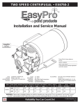
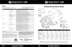
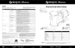
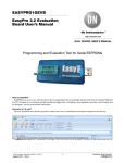
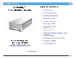
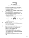
EXT Series
Installation and Service Manual
for EXT75, EXT180, EXT300, EXT1500
EasyPro
XXXXXXXXX
S/N: XXXX-XXXXXX
TYPE:
MOTOR:
PORT SIZE:
HORSEPOWER:
HARDWARE:
SEAL OPTIONS:
END-SUCTION CENTRIFUGAL
NEMA 143JM-215JM
3" FLANGED INLET, 2" FLANGED DISCHARGE
3/4 HP THROUGH 15 HP
STAINLESS STEEL
STAINLESS STEEL WITH BUNA AND VITON
Please fill in for future reference:
MODEL: ______________________________________
SERIAL NUMBER: _____________________________
DATE PURCHASED: ___________________________
* Please fill out the warranty registration card in this manual
WARNING: Please read completely before you install or operate your new pump! Do NOT allow this pump to become
submerged! Never run dry - Never reverse rotation. Never exceed an internal case pressure of: 100 PSI.
Reliability You Can Count On!
© 2010 EasyPro, Inc
Pg. 1
EXT Series
We congratulate you on your choice of the EXT Series Centrifugal Pump! It has been carefully designed using the advantages of today’s
technology and carefully constructed to give you the dependability of yesterday. To insure proper performance, we urge you to carefully
follow the instructions in this manual. If you have any questions, call your nearest distributor or EasyPro for assistance.
INSTALLATION
Please read carefully! When properly installed the EXT Series Pumps will provide dependable trouble-free service.
1. Locate the pump as near the fluid source as possible. A flooded suction situation is preferred.
2. Mount motor base to a secure, immobile foundation.
3. The pipe fittings should be self-supported and in neutral alignment with each port. (i.e. Fittings must not be forced into alignment
which may cause premature line failure or damage to the pump volute.)
4. Never restrict the intake. Keep both input and discharge lines as free of elbows and valves as possible. Always use pipe of adequate
diameter. This will reduce friction losses and maximize output.
5. The EasyPro EXT Series pump is not self-priming! It must not be run dry! We recommend a flooded suction installation. Please read
carefully! When properly installed, the EXT Pump will provide dependable, trouble-free service.
6. For additional plumbing tips, review EasyPro’s website: www.EasyProPondProducts.com for pond plumbing and pump installation
hints.
BALL
VALVE
FLOODED SUCTION
SUCTION LIFT
PUMP
FOOT VALVE
WARNING: DO NOT RUN DRY!
WARNING: ALWAYS SHUT OFF ELECTRICAL POWER BEFORE INSTALLATION AND / OR SERVICING THIS PUMP! ALL ELECTRICAL WIRING SHOULD
MEET STATE AND LOCAL ORDINANCES. IMPROPER WIRING MAY NOT ONLY BE A SAFETY HAZARD BUT MAY PERMANENTLY DAMAGE THE
MOTOR AND/OR PUMP! 50 HZ MOTORS AVAILABLE - CONTACT YOUR SUPPLIER FOR INFORMATION.
ELECTRICAL HOOK-UP
1. Check that supply voltages match the motor’s requirements.
2. Check motor wiring and connect, according to instructions on motor, to match supply voltage.
3. Verify motor rotation with rotation meter. Incorrect rotation can cause serious damage to pump and/or motor. EasyPro does not recommend checking rotation by quickly switching power on and off because serious damage can occur.
4. Power cord should be protected by conduit or by cable and be of proper gauge. It should be no longer than necessary.
5. Power should be drawn directly from a box with circuit breaker protection or with a fused disconnect switch.
Reliability You Can Count On!
© 2010 EasyPro, Inc
Pg. 2
EXT Series
PUMP END ASSEMBLY
1. Clean and inspect all pump parts (O-rings, seal heads, seal seats, motor shaft, etc.).
2. Place slinger (rubber washer) over motor shaft. Pump/bracket/impeller assembly can now be pulled back from volute.
3. Where applicable, check motor for rotation prior to assembling pump to motor.
4. For metallic seal head assembly installation: apply sealant to the bracket bore ID wall and around the seal case - follow sealant
mfg instructions. We recommend using Gasgacinch®, Perrmatex®, or 3M™ 1300L. Silicone sealant can also be used. Press seal
head into bracket using a tool that will apply pressure to the seal case shoulder; do not apply pressure to the carbon or silicon
carbide seal head.
5. For seal seat installation: carefully lubricate the seal seat elastomer OD and impeller hub ID with water. Press the seal seat into the
impeller hub making certain that the ceramic is bottomed and sits evenly - the sealing surface should be parallel with the impeller
hub.
6. Align bracket with holes in motor face and mount bracket to motor with four 3/8" ID x 1" OD washers and four 3/8" - 16 x 1" long
stainless steel hex cap screws using 9/16" wrench. (Use 1/2" - 13 x 1" long stainless steel hex head cap screws and 1/2" washers for
frame sizes 213JM and above, using 3/4" wrench.)
7. Assemble 3/16" square x 11/2" long stainless steel key in groove of motor shaft.
8. Assemble 3/8" - 16 x 13/4" long stainless steel threaded rod with hex recess into end of motor shaft, using 3/16" allen wrench.
Threaded rod should extend from shaft approximately .720 +/- .050" (reference Fig. 1 of insert drawing).
9. Carefully clean carbon-graphite and ceramic sealing surfaces with lint-free tissue and alcohol. Do not use silicone lubricants or
grease!
10. Slide impeller on motor shaft, aligned with key.
11. Assemble special impeller washer over threaded rod. Secure with 3/8" - 16 stainless steel hex jam nut using 9/16" long reach socket;
hold impeller while tightening.
12. Lightly grease cap O-ring with silicone grease, assemble cap with O-ring over threaded rod and tighten with 11/16" socket. Do not
over tighten.
13. Assemble large O-ring in groove in bracket. Use silicone grease only if necessary.
14. Assemble volute to bracket using five 5/16" - 18 x 4" long stainless steel hex head cap screws, ten 5/16" flatwashers, five 5/16" lockwashers and five 5/16" - 18 hex nuts. Use three 5/16" - 18 x 11/4" long stainless steel hex head cap screws with flat washers, lockwashers and nuts in the threaded inserts in the volute), using 1/2" wrench.
15. Assemble drain plug in volute drain hole and tighten. Use teflon tape or equivalent.
16. Before operating pump, allow a proper cure time for the sealant used in step 4.
17. Note: For assembling a discharge flange, use 5/8" x 21/4" long bolts, narrow washers, and hex jam nuts (provided in the discharge
piping hardware kit).
DISASSEMBLY
1. Shut off power to motor before disconnecting any electrical wiring from the motor.
2. Disassemble volute from bracket by removing the five 5/16" - 18 x 4" long hex cap screws, and the three 5/16" - 18 x 11/4" hex cap
screws. Pump/bracket/impeller assembly may now be pulled back from the volute.
3. Remove impeller eye ‘cap’ by unscrewing counterclockwise. Remove 3/8" nut using 9/16" socket wrench, unscrew counterclockwise. Slide impeller off of motor shaft.
4. Remove ceramic piece from impeller. Eye protection is strongly recommended. (If you are replacing the seal)
5. Detach bracket from motor.
6. Remove mechanical seal from bracket by pressing out from the back. Do not dig out from the front! (If you are replacing the seal).
Reliability You Can Count On!
© 2010 EasyPro, Inc
Pg. 3
EXT Series
MAINTENANCE
Lubrication
Rotary Seal - requires no lubrication after assembly.
*The pump must be drained before servicing or if stored
below freezing temperatures. Periodic replacement of
seals may be required due to normal carbon wear.
TROUBLE SHOOTING AID
Motor will not rotate
1. Check for proper electrical connections to motor.
2. Check main power box for tripped circuit breaker.
Motor hums or will not rotate
1. Check for proper electrical connections to motor and proper wire size according to local electrical codes.
2. Check for foreign material inside pump.
3. Remove volute and check for impeller rotation without excessive resistance and/or noise.
4. Remove pump and check shaft rotation for excessive bearing noise.
5. Check start switch and/or capacitor.
Pump operates with little or no flow
1. Check to insure that pump is primed.
2. Check for leaking seal.
3. Improper line voltage to motor or incorrect rotation.
4. Check for clogged inlet port and/or impeller.
5. Defective check or foot valve.
6. Check inlet lines for leakage, either fluid or air.
7. Verify rotation direction of impeller (see page 2).
Pump loses prime
1. Defective check or foot valve.
2. Inlet line air leakage.
3. Seal leaking.
4. Fluid supply low.
Motor or pump overheats
1. Check for proper line voltage and phase, also proper motor wiring.
2. Binding motor shaft or pump parts.
3. Inadequate ventilation.
4. Fluid being pumped should not exceed 194°F (90°C) for extended periods of time.
EASYPRO LIMITED WARRANTY
This product is warranted to the initial purchaser to be free of defects in materials and workmanship at the time of initial purchase and for a period of three years. In
the event this product malfunctions within three years from the date of purchase, the sole obligation of EasyPro, Incorporated (hereinafter referred to as EP) will be
to repair the unit or replace with an equivalent new or factory refurbished unit at EP’s discretion, subject to the following conditions:
1. You MUST call EP for a return authorization (RA#) number prior to returning, pumps returned without an RA# will be refused.
2. The malfunction is proved attributable to a defect in materials or workmanship, including repairs performed under this warranty. Malfunction for any other
reason — including but not limited to misuse, negligence, accident, tampering with parts, incorrect wiring, improper installation — will not be remedied
under this warranty.
3. EP specifically does not guarantee chemical compatibility, and expressly does not warrant units from any problems caused by chemical attack or failure due
to incompatibility of fluid being pumped with pump materials of construction.
4. All warranty repairs must be performed by EP or an EP authorized company. Purchaser must retain the purchase receipt and present it with this certificate
as proof of ownership and entitlement to warranty repairs. Unauthorized repairs will not be compensated by EP, are not the responsibility of EP, and if such
repairs damage the product, such damages are not remedied under this warranty.
5. Purchaser shall bear all shipping, packing and insurance costs and all other costs, excluding labor and parts necessary to effectuate repairs under
this warranty.
6. Periodic check-ups are not covered by this warranty.
7. This warranty is in lieu of all other express warranties which now or hereafter might otherwise arise with respect to this product. Any and all limited warranties,
including the warranties of merchantability and fitness for particular purpose, shall have no greater duration than the duration period of the express written
warranty applicable to this product, and shall terminate automatically the expiration of such duration period. Some states do not allow limitations on how
long an implied warranty lasts, so the above limitation may not apply to you. No action shall be brought for breach of any implied or express warranty after
one year subsequent to the expiration of the duration period of the express written warranty.
8. Incidental and consequential damages caused by malfunction, defect, or otherwise, and with respect to breach of any express or implied warranty, are
not the responsibility of EP, and, to the extent permitted by law, are hereby excluded both for property damage and, to the extent not unconscionable, for
personal injury damage. Some states do not allow the exclusion or limitation of incidental or consequential damages, so the above limitation or exclusion
may not apply to you.
9. This warranty does not apply to any malfunction arising out of any application of this product other than normal use, unless such application is upon request
specifically approved in writing by EP.
10. The provisions of this warranty are severable and if any provision shall be deemed invalid, the remaining provisions shall remain in full force and effect.
11. Rights under this warranty are not assignable without the express prior consent in writing by EP and, regardless of the terms of such consent in writing, such
assignee shall have no greater rights than his assignor had against EP.
Name: ________________________________________
Address:______________________________________
City: _______________ State: _____ Zip: __________
Model: _______ Serial Number: __________________
Date purchased: ______Where purchased: ________
Activate your warranty by filling out this form and mailing to EasyPro Pond Products
EasyPro Pond Products
4385 East 110th, Grant, MI 49327
800-448-3873 • 231-834-5537 fax
www.EasyProPondProducts.com
Gasgacinch® is a registered trademark of Porter Manufacturing. Noryl® is a registered trademark of the
General Electric Company. Teflon® is a registered trademark of DuPont Company.
5-10
Reliability You Can Count On!
© 2010 EasyPro, Inc
Pg. 4