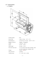
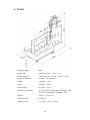
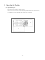
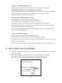
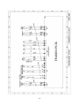
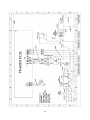
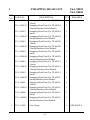
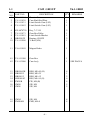
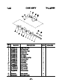
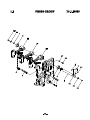
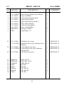
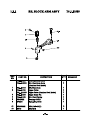
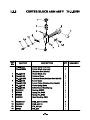
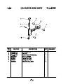
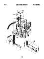
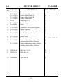
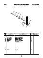
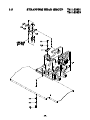
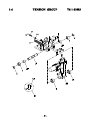
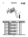
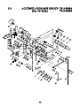
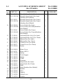
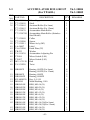
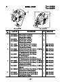
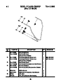
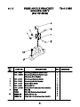
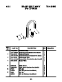
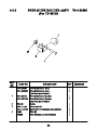
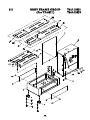
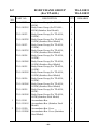
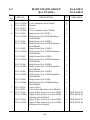
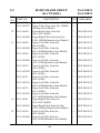
1
AUTOMATIC POLYPROPYLENE
STRAPPING MACHINE
TP-601D1
TP-601D3
TP-601L1
TP-601L3
OPERATION MANUAL
&
SPARE PARTS LIST
Original Instruction
READ ALL INSTRUCTIONS BEFORE OPERATING THIS PRODUCT
Explanations for Each Model NO. :
TP-601D1:Standard Single Phase Model
TP-601D3:Standard Three Phase Model
TP-601L1:Low Table Single Phase Model
TP-601L3:Low Table Three Phase Model
PART I
CONTENTS
1.
Safety Instructions ............................................................................. 1
(1) Before Operating ........................................................................... 1
(2) During operating............................................................................ 1
(3) After operating............................................................................... 1
(4) Signs .............................................................................................. 1
(5) Maintenance .................................................................................. 2
(6) Storage........................................................................................... 2
(7) Other Reminders............................................................................ 2
(8) Attention ........................................................................................ 2
2.
Construction and Function of Units ................................................... 3
3.
General Safety Remarks..................................................................... 5
(1) Basic Operation ............................................................................. 5
(2) Basic Safety Precautions ............................................................... 5
(3) Safety Instructions Governing Specific Operational Phases ......... 5
(4) Warning of Electrical Dangers....................................................... 6
(5) Grounding Instructions Shall Include the Following..................... 7
4.
Machine Information.......................................................................... 8
(1) Areas of Application and Machine Description............................. 8
(2) Technical Data ............................................................................... 9
(3) Control Panel ................................................................................11
(4) Electric Control Unit ................................................................... 12
5.
Operating the Machine..................................................................... 13
(1) Operation Space........................................................................... 13
(2) Installation of Arch Unit (For TP-601D) ..................................... 14
(3) How to Load P.P. Strap ................................................................ 16
(4) How to Operate............................................................................ 18
6.
Adjustments ..................................................................................... 19
(1) Heater temperature mechanism ................................................... 19
(2) Feed and take-up mechanism ...................................................... 20
(3) How to adjust LS3, LS2 .............................................................. 21
(4) Amount of strap in Accumulator Box ......................................... 23
7.
Maintenance..................................................................................... 25
8.
How to Safely move the Machine.................................................... 26
9.
Troubleshooting ............................................................................... 27
10.
Wiring Diagram ............................................................................... 28
1. Safety Instructions
(1) Before Operating
a. Read the instruction manual.
b. Wear eye protection and safety gloves before operating this machine.
Eye protection must be worn
Safety gloves must be worn Ear-protector must be worn
c. Verify that the power line voltage is correct.
d. The machine must be properly grounded to avoid a shock hazard. All wiring must be in
accordance with local wiring standards.
e. The strapping machine can only be operated with polypropylene (P.P.) strapping; do not
use polyester (PET) strapping or polyethylene (PE) cord strap.
(2) During operating
a. The weight of the package cannot exceed 100 kg (220 lbs),
b. The size of the package should not be less than 130mm (width) × 20mm (high) (5.1” ×
0.79”).
c. Check if the machine emits any smokes or unusual sound when it is running.
d. Keep away from the inside of the arch while the machine is operating; do not put your
hands or body into the arch when the machine is running.
(3) After operating
a. Remove dust and dirt from the unit; pay particular attention to the interior of the arch.
b. Turn off the power when the machine is not in use.
(4) Signs
Caution!
Electric Shock Hazard
-1-
Caution!
Hot!
Do not touch!
Warning for danger!
Do not put your hands or body
into arch working area when
machine is operating.
(5) Maintenance
a. Turn off the power before removing either of the top covers.
b. The heater tongue is very hot; do not touch it.
(6) Storage
a. The store room must be dry.
b. Do not expose the machine to extreme cold or heat environment.
c. Place the machine on an even floor in order to avoid any distortion.
(7) Other Reminders
a. A operation manual must remain attached to the machine at all times.
b. Do not alter the equipment or circuitry unless authorized to do so by the manufacturer.
(8) Attention
When the machine arrives in your warehouse, you need to use a forklift to take it off from
the pallet. If you could go down to the bottom side of the machine, you would see an
indication sticker as follows: (TP-601L)
Follow this sticker and lead the teeth of a forklift to that indicated position. After making
few distance adjusting, you then could drive the teeth in and take off the machine.
-2-
2. Construction and Function of Units
a.
TP-601D
1 Strapping head unit
This unit is the most important part of
the machine for cutting and sealing of
P.P.
2 Bandway unit
This is the arch track through which
P.P. strap forwards or reverses.
5 Body frame unit
4 Reel unit
Holds the strap coil. (If strap
core is 280mm, you can take
off the center drum to have
core size 200mm.)
6 Electric control unit
8 Auto strap feeding unit
3 Accumulator unit
This unit accumulates the quantity of strap
required for smooth feeding into the chute track.
-3-
b.
TP-601L
4 Reel unit
Holds the strap coil.
(If strap core is 280mm, you can take off the
center drum to have core size 200mm.)
3 Accumulator unit
This unit accumulates the
quantity of strap required for
smooth feeding into the chute
track.
2 Bandway unit
This is the arch track
through which P.P. strap
forwards or reverses.
8 Auto strap feeding
6 Electric control unit
5 Body frame unit
1 Strapping head unit
This unit is the most important part of the
machine for cutting and sealing of P.P. strap.
-4-
3. General Safety Remarks
(1) Basic Operation
The machine is only to be operated when in good running condition and in accordance
with the instructions provided in the operation manual. Operators must be trained in
proper operation and safety of the equipment.
The machine may only be operated in accordance with its designated use.
(2) Basic Safety Precautions
In addition to the instructions for operation, the user is to be instructed in all generally
applicable legal or mandatory regulations relevant to safety or the environment.
Long hair, loose-fitting garments, or jewelry can be a safety hazard. These items must be
secured prior to equipment operation.
Use protective equipment whenever appropriate or when required by law.
Carefully observe all safety instructions and warnings attached to the machine. Keep
safety labels clean and legible.
People that are being trained to operate or service the equipment must be supervised by
experienced personnel.
Any electrical work performed on the equipment must be conducted by a skilled
electrician or under the supervision of a skilled electrician. All work must observe good
electrical engineering practice and follow safety rules and local wiring standards.
(3) Safety Instructions Governing Specific Operational Phases
Avoid unsafe operation of the equipment.
The machine is only to be operated when it is in good running order. Only operate the
equipment in a safe manner; all protective and safety devices must be in place and fully
functional. This includes removable safety devices, emergency shut-off equipment,
noise-protection devices and exhaust fans.
The machine is to be checked for damage and defects at least once each work shift. Any
changes, including the working behavior of the machine, are to be reported immediately. If
necessary, the machine is to be stopped and locked-out immediately.
In case of a malfunction, the strapping machine is to be immediately stopped and
locked-out until the fault has been eliminated.
-5-
Before starting the strapping machine, make sure that the area is clear and safe.
Operating personnel need to be briefed before executing special operations and
maintenance work; this work needs to be done with the proper supervision.
Always check and tighten connections after maintenance or repair.
After completing maintenance or repair, all safety devices must be replaced and checked
for functionality before operating the equipment.
To minimize the environmental impact, all consumables and replaced parts must be
disposed of safely.
Before starting the machine, check that the accessories have been stowed away safely.
Avoid operating the machine in a fashion that could upset its stability.
(4) Warning of Electrical Dangers
Electrical Energy
Immediately remove power to the machine in case of trouble in the electrical system.
Replace a fuse with one with the same style and ratings; pay particular attention to
matching the specified current.
Any electrical work performed on the equipment must be conducted by a skilled
electrician or under the supervision of a skilled electrician. All work must observe good
electrical engineering practice and follow safety rules and local wiring standards.
Inspect the electrical equipment of the machine at regular intervals. Tighten any loose
connections. Check wiring for scorch marks; replace scorched wiring and determine and
correct the reason for the overheating.
When working on live equipment, ensure that a second person is available to cut power in
case of an emergency. When appropriate, secure the working area with safety tape and a
warning sign. Use insulated tools for electrical work.
Before working on high-voltage assemblies, turn off the power supply. Carefully discharge
the supply cable and short-circuit any energy-storage components such as capacitors.
If the equipment was moved, carefully refit and refasten all parts removed for transport
before reapplying power.
Before moving the machine, remember to disconnect the power cable.
-6-
(5) Grounding Instructions Shall Include the Following
This product must be grounded. In the event of an electrical short circuit, grounding
reduces the risk of electric shock. This product is equipped with a cord that has a
grounding wire and an appropriate grounding plug. The plug must be plugged into an
outlet that is properly installed and grounded in accordance with all local codes and
ordinances.
If repair or replacement of the cord or plug is necessary, connect the ground wire to the
ground terminal of the plug. The wire with green insulation (with or without yellow stripes)
is the grounding wire.
Check with a qualified electrician or service person if the grounding instructions are not
clear or if in doubt about the proper grounding of the machine. Do not modify the plug
provided; if it will not fit the power outlet, have the proper outlet installed by a qualified
electrician.
DANGER!
Improper installation of the grounding can result in electrocution.
-7-
4. Machine Information
(1) Areas of Application and Machine Description
This plastic strapping machine can be used for all types of strapping applications with
package sizes of 130 mm(width) × 20 mm(height) and up.
This machine is particularly suitable for heavy packaged goods as well as printed products,
boxes, etc.
Machine Description
Automatic plastic strapping machine for use with polypropylene strapping
Extra tough construction
Simple, safe and user-friendly operation
Automatic feeding-system
Automatic strap-end detection
Loop ejection
Mobile, with large table area and high capacity strap reel
Table surface made of stainless steel
Strap tension adjustable from soft to extremely high
Environment Information
The strapping machine shall be installed in the following conditions:
z Supply voltage: 0.9 - 1.1 nominal supply voltage
z Source frequency: 0.99 - 1.01 nominal frequency
z Ambient temperature: 5°C - 40°C (41℉-104℉).
z
z
Relative humidity: not exceed 50% at 40°C.
Please provide a suitable illumination around the machine for safety operation.
-8-
(2) Technical Data
a. TP-601D
Sealing method :
Heat
Strap width :
8 mm to 12 mm
Strap thickness :
0.55 mm up to 0.75 mm
Strap reel diameter :
200 mm (8" nominal)
Width :
1430 mm (56.3")
Depth :
620 mm (24.4")
Table height :
810 mm (31.9")
Electrical connection :
AC 110V/220V/230V/240V (50/60Hz), 1PH
(3/8" - 1/2")
(0.022" - 0.03")
AC 220V/380V/400V (50/60Hz), 3PH
Weight :
220 kg
(485 lbs.)
Noise emission :
83 dB (A)
Ambient temp :
5℃ ~ 40℃ (41℉ ~104℉)
-9-
b. TP-601L
Sealing method :
Heat
Strap width :
8 mm to 12 mm
Strap thickness :
0.55 mm up to 0.75 mm
Strap reel diameter :
200 mm (8" nominal)
Width :
1880 mm (74")
Depth :
620 mm (24.4")
Table height :
410 mm (16.1")
Electrical connection :
AC 110V/220V/230V/240V (50/60Hz), 1PH
(3/8" - 1/2")
(0.022" - 0.03")
AC 220V/380V/400V (50/60Hz), 3PH
Weight :
235 kg
(518.1 lbs.)
Noise emission :
83 dB (A)
Ambient temp :
5℃ ~ 40℃ (41℉ ~104℉)
- 10 -
(3) Control Panel
TP-601D
1
○
Start Switch
This is the switch to start a strapping operation.
A strapping cycle is completed only after
actuation of this switch. (Indicator for strap goes
to ready position)
2
○
Reset switch
This is the switch to activate auto strap feeding.
In addition, it is used for troubleshooting. If
the strap is mis-fed, you can push this button to
solve the problem.
3
○
selector switch
While selector switch is placed to the position
, the machine will automatically strap the
package when it is placed on the table and passes
the chute arch, if the package remains under the
arch, the strapping cycle will continue. While
the selector switch is placed to the position
,
after positioning the package under the arch,
push the "START" switch, then one strap will be
applied.
4
○
Tension Adjustment Knob
External adjustment of strap tension by
step-by-step rotation of this knob.
- 11 -
TP-601L
(4) Electric Control Unit
Timer, T1
30 :
○
T1 timer determines the time necessary for strap take-up. While setting, please test with
the minimum sized package. Normally, Timer T1 is set at about 0.5 second, but may
have to be adjusted depending on arch size & actual package size.
TP-601D1
TP-601L1
TP-601D3
TP-601L3
- 12 -
5. Operating the Machine
(1) Operation Space
Keep the area (A) and (B) free for the operator.
The area (A) is necessary for operation strapping machine and the area (B) is necessary
for changing the strap or adjusting strap amount in the accumulator.
B
A
- 13 -
(2) Installation of Arch Unit (For TP-601D)
- 14 -
1 ,
a. Take the upper table ○
15
○
off.
2 off.
b. Take the LH bandway ○
6
○
11
○
18
○
TMS, M5×8
1PC
HBS, M8×15
4PC
PW, M8 (A)
4PC
8
○
12
○
TMS, M6×8
2PC
SW, M8
4PC
3 into the fixing brackets ○
4 and fix both sides of the arch frame
c. Slide the arch unit ○
with
11 ○
12 ○
18 .
○
5 to protect them
* Please note that is imperative to open the flaps of RH bandway ○
when installing the arch unit in. (open the flaps, before inserting the arch unit in)
2 , with ○
6 and ○
8 .
d. Set the LH bandway ○
d-1. Please note that the arch bandway (refer Fig. A) should be positioned between LH
bandway and its fixing bracket.
2 closely to ○
17 guiding angle (PART NO.
d-2. Please set the LH bandway ○
T6-2-21260).
16 Band guide Spring Bracket backward to check if B will be
d-3. Push the ○
automatically turned open. If so, the installation is OK.
1
e. Position the upper table ○
15
○
onto the machine body.
- 15 -
(3) How to Load P.P. Strap
a. TP-601D
z Ensure that the power switch is
turned off before loading P.P.
strap.
Step 1
Place a strap coil on the reel drum in
according to the arrow direction as
9 .
indicated on the Reel Out Circular ○
After placing it, put the Reel Out
Circular on the strap coil and tighten it
10 .
by the Reel Nut Handle ○
Step 2
Thread the tip of P.P. strap into the
11 . After that,
Band Guide Roller ○
12 .
push it through the Free Angle ○
At this moment, twist the strap so that the inside part
of the P.P. strap turns out downward and outside
surface touches on the roller. See the drawing.
Step 3
Insert P.P. strap into the Pool Feed Shooter
pushing the lever
14
○
13
○
,
down and feed P.P. strap about
1-2 cm beyond Pool roller
15
○
Step 4
Turn on the power supply switch, and then push Reset
17 . After about 4 seconds, the strap will
Switch ○
automatically go into the arch and pool.
- 16 -
b. TP-601L
z Ensure that the power switch is
turned off before loading P.P.
strap.
Step 1
Place a strap coil on the reel drum in
according to the arrow direction as
9 .
indicated on the Reel Out Circular ○
After placing it, put the Reel Out
Circular on the strap coil and tighten it
10 .
by the Reel Nut Handle ○
Step 2
Thread the tip of P.P. strap into the
12 . After that,
Roller Bracket Ass'y ○
thread it through the Band Guide Roller
11 .
○
Step 3
Insert P.P. strap into Pool Feed Shooter
13 and turn Accumulator Main Roller
○
14
○
until the P.P. strap about 1-2 cm
beyond the Main Roller
14 .
○
Step 4
Turn on the power supply switch, and
17 . After
then push Reset Switch ○
about 4 seconds, the strap will
automatically go into the arch and pool.
- 17 -
(4) How to Operate
a. Turn on the Main power switch (make a 90-degree clockwise turn). The front door will
be locked at the same time. [If you want to open the front door, turn off the main
power switch first (make a 90-degree counterclockwise turn). In this way, the operator
can open the front door without risk.] (See drawing below)
b. Wait for about 3 minutes until the heater element reaches its required operating
temperature.
c. Place a package in the middle of the chute.
4 )
d. Set tension with Tension Adjustment Knob (VR)(see page part I P11 ○
1 ) or actuate foot pedal switch to start strapping.
e. Push start switch (see page part I P11 ○
The strapping operation is repeated if the start switch is pushed again.
- 18 -
6. Adjustments
(1) Heater temperature mechanism
Set the knob to position 3 or 4
Adjust the heater temperature by selecting a value between 1 and 6.
Choose the suitable temperature, bearing in mind the environmental conditions of the
machine.
If the heater temperature is too high or too low, a proper seal will not be obtained.
Gradually increase or reduce the heater-knob value until obtaining an optimum seal.
- 19 -
(2) Feed and take-up mechanism
If this unit is not correctly adjusted, strap feed
and take-up will become irregular.
Normally, this unit is set to accept P.P. strap
with the thicknesses of 0.55mm-0.75mm. If a
different strap thickness is used, adjust the
section marked by a circle in the drawing so that
the clearance between the Upper Roller Spring
23
○
and the Upper Shaft Spring Hook
24
○
should be the thickness of the strap you are
using. Strap can only be taken up properly if
this unit is precisely adjusted. (If not, strap
will be sealed before being tightened around the
package) Moreover, strap will leave the chute
arch track when feeding into it if there is no
clearance.
a. Check if the control unit returns to its
original position. Insert the strap between
22 and Upper Feed Roller
Feed Roller ○
21 .
○
b. Loosen 2 Bolts
27
○
holding the right-hand
25 with the Press Arm Shaft ○
26 .
Block Arm ○
Press Arm Shaft can then easily be moved by
hand.
c. Adjust so that there is a clearance between the
23 and the Upper Shaft
Upper Roller Spring ○
24 the same as the thickness of
Spring Hook ○
the strap you are using.
d. Tighten 2 Bolts
27
○
.
The thickness of the
strap you are using
- 20 -
(3) How to adjust LS3, LS2
Figure 1: LS-3 Home Position
Figure 1-1
M6 screw
Cam Follower
Tension Cam
Figure 1: LS-2
Figure 2-1
Take-up
Cooling Time
Feeding
Figure 1 shows the correct position for LS3 Proximity Sensor
Cam
32
○
32
○
and the Limit Switch
while the machine is in home position.
The machine will stop as soon as the LS3 Proximity Sensor
Cam
31
○
is activated.
At this time, the Cam Follower
position on the Tension Cam
to the following instructions.
42
○
41
○
as shown in figure 1-1.
31
○
detects that Limit Switch
must stop at the corner
If not, please adjust according
Adjustment
41 stops before the correct position:
If Cam Follower ○
a. Loosen the two M6 screws and turn the Cam Roller slightly clockwise, then tighten
the M6 screws.
41
b. Reset the machine and allow it to cycle again to ensure that the Cam Follower ○
stops at the correct position.
c. If the problem has not been eliminated, please repeat the "Step One" until the Cam
41 stops at the correct position.
Follower ○
- 21 -
41 stops beyond the correct position:
If Cam Follower ○
Please also loosen the M6 screws but turn the Cam Roller slightly counterclockwise until
41 stops at the correct position.
the Cam Follower ○
33 against the lobes of
Figure 2 shows the correct position for LS2 Proximity Sensor ○
34 while machine is running.
the Limit Switch Cam ○
When LS2 Proximity Sensor
33
○
detects Lobe A of the activated running Limit Switch
34 , the machine will stop about 0.3 seconds so that the machine can switch to
○
41 has to stay on the corner position of the
take-up. In the meantime, Cam Follower ○
42 as shown in figure 2-1. If the Cam Follower is not at the correct
Tension Cam ○
Cam
position, please make the same adjustment as for LS3.
- 22 -
(4) Amount of strap in Accumulator Box
a. TP-601D
The machine has already been set in its Accumulator Box.
However, some adjustment may be required, depending on the actual quality or
thickness of the strap used. If adjustment is necessary, proceed as shown in the
following drawing.
a-1. In case that there is an insufficient amount of strap in the Accumulator Box,
27 and turn the Screw Bolt ○
28 counterclockwise.
loosen the Nut ○
a-2. In case that there is an excessive amount of strap in the Accumulator Box, loosen
27 and turn the Screw Bolt ○
28 clockwise.
the Nut ○
- 23 -
b. TP-601L
Fig A:
If you have moved the LS4 Micro Switch to the left up to the bottom but you still do
not have enough P.P. strap in the accumulator box, you can loosen nut E and turn the
bolt D C.C.W. increase the amount of P.P. strap in the accumulator box. Finally
tighten the nut E.
T7-3-10190
Micro Switch (LS4)
M6 Screw
T7-3-10200
- 24 -
7. Maintenance
Warning:
Before any maintenance or repairs on the machine, set the Main Power
Switch to "O" (OFF). Wait about 5 minutes for cooling down the heater to
avoid burns with this area.
(1) Cleaning and Lubrication
The high reliability and long service life of the strapping machine will depend on regular
cleaning and maintenance.
ATTENTION!
All the important strap transport components, such as the feeding rollers and the
strap guides, must be kept free from oil and grease. (lubricant)
The lubricant has to be non-resinous.
The lubricant is SAE 30
(2) Maintenance
Only use original spare parts supplied by manufacturer.
Daily:
Use air gun to clean the circled positions (nearby the cutters, strap guide and
accumulating feeding rollers) daily
Remove plastic residue in the machine.
- 25 -
Monthly :( or 50,000 strapping cycles)
Clean both sides of heater plate and polish with fine sandpaper if necessary
ATTENTION: Make sure the welding plate is cool first!!
Check supporting and cam rollers of strapping head for easy movement. The slide table
must be moved back to home position automatically by the spring tension.
Be sure to clean any debris in the tension jaw.
6 Months:(or 300,000 strapping cycles)
Check heater plate, replace and readjust it if necessary.
Check strap cutter in strapping head, replace it if necessary.
Check that connector at wiring loom to printed circuit board is firmly fixed.
Make machine ready for operation. Strap one bundle manually several times, paying
attention to mal-functions, repeat procedure.
Check strap accumulating function. Do proper adjustments to accumulating feeding
pressure or the reel brake belt
1 year :( or 600,000 strapping)
Replace deflection roller if it shows visible changes.
In case of loud noise at bearings: locate them, replace the bearings.
Get machine ready for operation again, strap one bundle manually several times, paying
attention to malfunctions.
NOTE: Any other service must be performed by an authorized service representative.
8. How to Safely move the Machine
a.
b.
Before moving the machine, be sure to unplug the power cord and put it in safe place to
avoid any damage.
Moving the machine by holding the Reel Guard to pull or push the machine.
Note: Don’t move the machine by pulling or pushing the arch unit.
- 26 -
9. Troubleshooting
(1) Incorrect strap feed and take-up
Probable Causes
Remedy
a. Incorrect strap threading direction on a. Reload strap correctly (see page 16)
reel holder
b. Incorrect loading of strap
b. Check if strap is twisted in loading section
(see page 16)
c. Strap gets in between strap coil and
Reel Flange
c. Reload strap
d. Insufficient or excessive strap
d. Adjust amount of strap accumulated (see
page 23)
e. Dust and strap residues in Feed Unit
e. Check and clean unit
f. Strap end is split
f. Adjust Cutter Tension Spring or change
cutter
g. Loose strap at Reel Unit
g. Adjust or change Brake Tension Arm
Spring
h. Strap jumps out of arch track
h. Adjust F/R mechanism (see page 20)
i. Poor quality of strap
i. Cut off the damaged part of strap or
change the roll
j. Improper positioning of package on j. Replace the package in the center of the
Table Top
Sealing Head
(2) Strap unsealed
Probable Causes
Remedy
a. Wire inside or outside of Heater is
broken, loose or out of connect
a. Check wire or change Heater
b. Improper setting of temperature
b. Adjust Heater Temperature (see page 19)
c. Value set at Tension knob is too high
c. Adjust Tension Knob (see page 11) or
increase weld cooling time
(3) Improper strap tensioning
Probable Causes
Remedy
Value set for Timer T1 is too short
- 27 -
Adjust Timer T1 (see page 12)
10. Wiring Diagram
- 28 -
- 29 -
- 30 -
- 31 -
- 32 -
- 33 -
- 34 -
- 35 -
- 36 -
- 37 -
- 38 -
- 39 -
- 40 -
- 41 -
- 42 -
- 43 -
PART II
CONTENTS
1. Strapping Head Unit …………………………………
1
2. Bandway Unit ………………………………………31
45
3. Accumulator Unit ……………………………………
4. Reel Unit ……………………………………………59
5. Body Frame Unit ……………………………………70
6. Electric Control Group ………………………………
98
7. Auto Strap Feeding Unit ……………………………109
1
STRAPPING HEAD UNIT
REF.
PART NO.
NO.
T6-1-90051
T6-1-90051S
T6-1-90052
T6-1-90052S
T6-1-90053
T6-1-90053S
T6-1-90054
T6-1-90054S
T6-1-90061
T6-1-90061S
T6-1-90062
T6-1-90062S
T6-1-90063
T6-1-90063S
T6-1-90064
T6-1-90064S
1
T6-1-10003
DESCRIPTION
Strapping Head Unit (For TP-601D1,
12mm)
Strapping Head Unit (For TP-601D1,
12mm)(Stainaless Steel Model)
Strapping Head Unit (For TP-601D1,
9mm)
Strapping Head Unit (For TP-601D1,
9mm)(Stainaless Steel Model)
Strapping Head Unit (For TP-601D3,
12mm)
Strapping Head Unit (For TP-601D3,
12mm)(Stainaless Steel Model)
Strapping Head Unit (For TP-601D3,
9mm)
Strapping Head Unit (For TP-601D3,
9mm)(Stainaless Steel Model)
Strapping Head Unit (For TP-601L1,
12mm)
Strapping Head Unit (For TP-601L1,
12mm)(Stainaless Steel Model)
Strapping Head Unit (For TP-601L1,
9mm)
Strapping Head Unit (For TP-601L1,
9mm)(Stainaless Steel Model)
Strapping Head Unit (For TP-601L3,
12mm)
Strapping Head Unit (For TP-601L3,
12mm)(Stainaless Steel Model)
Strapping Head Unit (For TP-601L3,
9mm)
Strapping Head Unit (For TP-601L3,
9mm)(Stainaless Steel Model)
Cam Group
T6-1-90051
T6-1-90052
Q'TY
1
1
1
1
1
1
1
1
1
1
1
1
1
1
1
1
1
-2-
REMARKS
SEE PAGE 4
1
STRAPPING HEAD UNIT
REF.
PART NO.
NO.
2
T6-1-20020
T6-1-20020S
3
4
5
6
7
T6-1-30000
T6-1-30000S
T6-1-40000
T6-1-50031
T6-1-50032
T6-1-60003
T6-1-60003S
T6-1-70002
T6-1-70002S
T6-1-70003
T6-1-70003S
T6-1-70004
T6-1-70004S
T6-1-70005
T6-1-70005S
T6-1-90051
T6-1-90052
DESCRIPTION
Q'TY
Slide Table Group
Slide Table Group (Stainaless Steel
Model)
Press Group
Press Group (Stainaless Steel Model)
Heater Group
Strapping Head Group (For TP-601D)
Strapping Head Group (For TP-601L)
Tension Group
Tension Group (Stainaless Steel
Feed Group (For TP-601D1/TP-601L1,
12mm)
Feed Group (For TP-601D1/TP-601L1,
12mm)(Stainless Steel Model)
Feed Group (For TP-601D1/TP-601L1,
9mm)
Feed Group (For TP-601D1/TP-601L1,
9mm)(Stainless Steel Model)
Feed Group (For TP-601D3/TP-601L3,
12mm)
Feed Group (For TP-601D3/TP-601L3,
12mm)(Stainless Steel Model)
Feed Group (For TP-601D3/TP-601L3,
9mm)
Feed Group (For TP-601D3/TP-601L3,
9mm)(Stainless Steel Model)
1
1
SEE PAGE 7
SEE PAGE 7
1
1
1
1
1
1
1
1
SEE PAGE 11
SEE PAGE 11
SEE PAGE 16
SEE PAGE 19
SEE PAGE 19
SEE PAGE 21
SEE PAGE 21
SEE PAGE 25
1
SEE PAGE 25
1
SEE PAGE 25
1
SEE PAGE 25
1
SEE PAGE 25
1
SEE PAGE 25
1
SEE PAGE 25
1
SEE PAGE 25
-3-
REMARKS
1-1
REF.
NO.
1
2
3
4
CAM GROUP
PART NO.
DESCRIPTION
T6-1-10003
Q'TY
T6-1-10110
T6-1-10120
T6-1-10131
T6-1-10142
Tension Cam
Cam Shaft End Plate
Limit Switch Cam (LS2)
Limit Switch Cam (LS3)
1
1
1
1
6
7
8
9
10
KYA070720
T6-1-10171
T6-1-10181
BR6205ZZ
T6-1-10200
Key, 7×7×20
Gear Box Pulley
Limit Switch Bracket
Bearing, 6205ZZ
V-Belt (A26)
2
1
1
2
1
11
T6-6-10180
Magnet Brake
1
41
42
T6-1-11000
T6-1-12000
Gear Box
Cam Ass'y
1
1
51
52
53
54
55
56
57
HBS0845H
HBS0825
HBS0612
HSS0610G
PW08B
SW08
SW06
HBS, M8×45 (H)
HBS, M8×25
HBS, M6×12
HSS, M6×10 (G)
PW, M8 (B)
SW, M8
SW, M6
4
1
2
6
4
5
2
61
62
SW04
PMS0408
SW, M4
PMS, M4×8
4
4
-5-
REMARKS
SEE PAGE 6
1-2
SLIDE TABLE GROUP
REF.
PART NO.
NO.
T6-1-20020
T6-1-20020S
1
2
4
5
6
7
8
9
10
11
12
14
15
16
17
18
19
20
21
27
41
50
51
52
53
54
55
56
57
60
61
DESCRIPTION
Slide Table Group
Slide Table Group (Stainless Steel
Model)
T6-1-20110
Slide Table Frame
T6-1-20120
Slide Table Frame Shaft
T6-1-20141
Slide Table Back Adjuster
T6-1-20150
Slide Table Stopper
T6-1-20163
Slide Table
T6-1-20163S1 Slide Table (Stainless Steel Model)
T6-1-20170
Strap Guide
T6-1-20180
Flap Connecting Spring Bracket
T6-1-20198
S.F.S. Ass'y
T6-1-20198S S.F.S. Ass'y (Stainless Steel Model)
T6-1-30170
Press Arm End Plate
T6-1-20220
Slide Table Spring Hook
T6-1-20230
Slide Table Tension Spring
BR6304ZZ
Bearing, 6304ZZ
T6-1-20250
Cam Follower, KR22×LL
ER15
Snap Ring, E-15
T6-1-20311
Support
T6-1-20323
Lever
T6-1-20340
Bracket
T6-1-20351
Spring
T6-1-20450
Bushing
T6-1-20372
Spring
T6-1-21000
Strap Guide Arm Ass'y
HBS0630
HBS, M6×30
HBS1025H
HBS, M10×25 (H)
HBS0830
HBS, M8×30
HBS0650H
HBS, M6×50 (H)
HBS0620N
HBS, M6×20 (N)
HBS0620S
HBS, M6×20 (Stainless Steel Model)
HBS0625
HBS, M6×25
HSS0810G
HSS, M8×10 (G)
TMS0610
TMS, M6×10
PW08A
PW, M8 (A)
PW06A
PW, M6 (A)
-8-
T6-1-20020
Q'TY
REMARKS
1
1
1
1
1
1
1
1
1
1
1
1
1
1
1
2
1
2
1
1
1
1
1
1
1
1
1
1
2
4
4
3
2
2
1
4
SEE PAGE 10
1-2
REF.
NO.
63
64
65
66
67
SLIDE TABLE GROUP
PART NO.
DESCRIPTION
T6-1-20020
Q'TY
SW06
HBS0616
HBS0408
TMS0412
HN08
SW, M6
HBS, M6×16
HBS, M4×8
TMS, M4×12
HN, M8
7
1
6
2
1
71
72
SW04
SW04S
SW, M4
SW, M4 (Stainless Steel Model)
9
1
74
NTE04
NTE, M4
1
76
77
HN06
SW03
HN, M6
SW, M3
4
2
80
81
82
83
TA-071
T6-1-20910
T6-1-20920
T6-1-20930
T6-1-20930S
HN03
HN04
HN04S
PMS0416
PMS0412
Return Spring
Sensor Plate
Loop-eject Lever
Loop-eject Plate
Loop-eject Plate (Stainless Steel Model)
HN, M3
HN, M4
HN, M4 (Stainless Steel Model)
PMS, M4×16
PMS, M4×12
1
1
1
1
1
2
3
1
1
1
FMS0508
FMS0508S
T6-1-20840
T6-2-10130
FMS, M5×8
FMS, M5×8 (Stainless Steel Model)
Detector Plate
LH Bandway Stop Spring
2
2
1
1
84
85
86
87
88
95
96
97
-9-
REMARKS
1-3
PRESS GROUP
REF.
PART NO.
NO.
T6-1-30000
T6-1-30000S
1
T6-1-30110
2
T6-1-30120
3
T6-1-30130
4
T6-1-30140
5
T6-1-30150
6
T6-1-30160
7
T6-1-30170
8
BR6304ZZ
9
ER15
DESCRIPTION
T6-1-30000
Q'TY
REMARKS
Press Group
Press Group (Stainless Steel Model)
Press Arm Shaft
Cutter Tension Spring Hook
Upper Roller Spring
Upper Shaft Spring Adjuster
Press Tension Spring
Cutter Tension Spring
Press Arm End Plate
Bearing, 6304ZZ
Snap Ring, E-15
1
1
1
1
1
1
3
1
1
2
1
1
1
SEE PAGE 13
SEE PAGE 13
1
1
SEE PAGE 14
SEE PAGE 14
1
SEE PAGE 15
41
T6-1-31000
T6-1-31000S
42
T6-1-32000
T6-1-32000S
43
T6-1-33000
RH, Block Arm Ass'y
RH, Block Arm Ass'y (Stainless Steel
Model)
Center Block Arm Ass'y
Center Block Arm Ass'y (Stainless
Steel Model)
LH, Block Arm Ass'y
51
52
53
54
55
56
57
58
HBS0620
HSS0615G
TMS0610
HN08
HN06
PW08A
PW06B
SW06
HBS, M6×20
HSS, M6×15 (G)
TMS, M6×10
HN, M8
HN, M6
PW, M8 (A)
PW, M6 (B)
SW, M6
- 12 -
1
2
2
2
2
1
2
1
1-4
REF.
NO.
1
2
3
4
5
6
7
8
HEATER GROUP
PART NO.
DESCRIPTION
T6-1-40000
Q'TY
T6-1-40110
T6-1-40120
T6-1-40130
T6-1-40140
T6-1-40150
ER15
T6-1-40170
LA-40002
Heater Cover
Heater Crank Spring
Heater Slider Guide (L)
Heater Slider Guide (R)
Heater Crank Shaft
Snap Ring, E-15
Heater Stopper
Label
1
1
1
1
1
2
1
1
21
22
23
24
T6-6-10920
T6-6-10930
T6-6-10940
T6-6-10970
Activated Carbon Filter (Option)
Nipple (Option)
Smoke-Exhaustion Pipe (Option)
Fan (For Smoke)(Option)
1
1
1
1
41
42
43
T6-1-41000
T6-1-42000
T6-1-43000
Heater Ass'y
Heater Crank Ass'y
Smoke-exhaustion system, with
activaed carbon filter. (Option)
Smoke-exhaustion system, without
activated carbon filter. (Option)
1
1
1
T6-1-43001
1
51
52
HSS0610G
HBS0616
HSS, M6×10 (G)
HBS, M6×16
2
4
56
TMS0408
TMS, M4×8
4
- 17 -
REMARKS
SEE PAGE 18
1-5
STRAPPING HEAD GROUP
REF.
PART NO.
NO.
T6-1-50031
T6-1-50032
1
T6-1-50100
2
T6-1-50111
T6-1-50031
T6-1-50032
DESCRIPTION
Q'TY
Strapping Head Group (For TP-601D)
Strapping Head Group (For TP-601L)
Strapping Head Frame
Band Width Block
1
1
1
1
52
54
55
56
HBS0820
HBS0825
HBS0620
PW06B
SW08
PW08C
HBS, M8×20 (For TP-601D)
HBS, M8×25 (For TP-601L)
HBS, M6×20
PW, M6 (B)
SW, M8
PW, M8 (C)
4
4
1
1
4
4
61
T6-1-50660
Bracket
1
63
64
HBS0612
SW06
HBS, M6×12
SW, M6
2
2
51
- 20 -
REMARKS
1-6
T6-1-60003
TENSION GROUP
REF.
PART NO.
NO.
T6-1-60003
T6-1-60003S
1
T6-1-60111
2
T6-1-60120
DESCRIPTION
Q'TY
Tension Group
Tension Group (Stainless Steel Model)
Tension Arm Shaft
Tension Arm Spring
1
1
1
1
4
T6-1-60140
Tension Arm Spacer
2
6
7
8
T6-1-60160
BRHK2516
ER15
Tension Arm Spring Hook L-Type
Bearing, HK2516
Snap Ring, E-15
1
2
2
11
BRIR202517
Bearing, IR202517
2
21
SP0680
Spring Pin, 6×80
1
41
42
T6-1-61001
T6-1-62000
T6-1-62000S
Tension Arm Ass'y
Tension Jaw Ass'y
Tension Jaw Ass'y (Stainless Steel
Model)
1
1
1
53
54
HN08
PW08B
HN, M8
PW, M8 (B)
2
1
- 22 -
REMARKS
SEE PAGE 23
1-6-1
REF.
NO.
19
20
21
22
TENSION ARM ASS'Y
PART NO.
DESCRIPTION
T6-1-61001
Q'TY
T6-1-61290
T6-1-61300
T6-1-61100
T6-1-61101
Support Plate
Collar
Bracket Set
Motor (M5-1) Set
1
3
1
1
48
49
50
51
52
SW08
SW05
MB1504
HSS0810G
HN08
SW, M8
SW, M5
Metal Bushing, 1504
HSS, M8×10 (G)
HN, M8
1
7
1
2
1
56
57
HN06
THS0540
HN, M6
THS, M5×40
1
3
- 24 -
REMARKS
1-7
FEED GROUP
REF.
PART NO.
NO.
1
T6-1-70111
T6-1-70112
41
T6-1-71002
T6-1-71002S
T6-1-71003
T6-1-71003S
42
T6-1-72000
T6-1-72030
DESCRIPTION
V-Belt M-22 (For TP-601D1/TP601L1)
V-Belt M-23 (For TP-601D3/TP601L3)
Feed Ass'y (For 12mm)
Feed Ass'y (For 12mm)(Stainless Steel
Model)
Feed Ass'y (For 9mm)
Feed Ass'y (For 9mm)(Stainless Steel
Model)
Upper Adjusting Weight Ass'y
(For TP-601D)
Upper Adjusting Weight Ass'y
(For TP-601L)
- 26 -
T6-1-70002
T6-1-70003
Q'TY
REMARKS
1
1
1
1
SEE PAGE 27
SEE PAGE 27
1
1
SEE PAGE 27
SEE PAGE 27
1
SEE PAGE 30
1
SEE PAGE 30
1-7-1
FEED ASS'Y
REF.
PART NO.
NO.
T6-1-71002
T6-1-71002S
T6-1-71003
T6-1-71003S
2
3
4
5
6
7
T6-1-71123
T6-1-71124
T6-1-71130
T6-1-71140
T6-1-71140S
T6-1-71150
T6-1-71160
T6-1-71170
T6-1-71170S
T6-1-71171
T6-1-71171S
8
T6-1-71180
T6-1-71180S
9
T6-1-71193
T6-1-71194
BR628ZZ
BR6202ZZ
RR24
RR35
ER12
10
11
12
13
14
51
HBS0645H
HBS0645HS
52
HBS0616
T6-1-71002
T6-1-71003
DESCRIPTION
Q'TY
Feed Ass'y (For 12mm)
Feed Ass'y (For 12mm)(Stainless Steel
Model)
Feed Ass'y (For 9mm)
Feed Ass'y (For 9mm)(Stainless Steel
Model)
1
1
Upper Feed Roller (For 12mm)
Upper Feed Roller (For 9mm)
Upper Feed Roller Shaft
Feed Roller
Feed Roller (Stainless Steel Model)
Lever Holder
Feed Roller Pulley
Feed Shooter (For 12mm)
Feed Shooter (For 12mm)(Stainless
Steel Model)
Feed Shooter (For 9mm)
Feed Shooter (For 9mm)(Stainless
Steel Model)
Feed Shooter Cover
Feed Shooter Cover (Stainless Steel
Model)
Upper Feed Roller Set (For 12mm)
Upper Feed Roller Set (For 9mm)
Bearing, 628ZZ
Bearing, 6202ZZ
Snap Ring, H-24
Snap Ring, H-35
Snap Ring, E-12
HBS, M6×45 (H)
HBS, M6×45 (H)(Stainless Steel
Model)
HBS, M6×16
- 28 -
1
1
1
1
1
1
1
1
1
1
1
1
1
1
1
1
1
1
4
2
4
1
2
2
1
REMARKS
1-7-1
REF.
NO.
53
54
55
56
FEED ASS'Y
PART NO.
HSS0615G
HSS0610G
PMS0610
PMS0610S
HN06
DESCRIPTION
HSS, M6×15 (G)
HSS, M6×10 (G)
PMS, M6×10
PMS, M6×10 (Stainless Steel Model)
HN, M6
- 29 -
T6-1-71002
T6-1-71003
Q'TY
1
2
2
2
2
REMARKS
2
BANDWAY UNIT
REF.
PART NO.
NO.
T6-2-90000
T6-2-90000S
T6-2-90007
T6-2-90007S
1
2
T6-2-10110
T6-2-10111
T6-2-10120
T6-2-10121
T6-2-10140
T6-2-10141
T6-2-10150
T6-2-10151
T6-2-10160
T6-2-10161
T6-2-10170
T6-2-10171
T6-2-10180
T6-2-10181
T6-2-20003
T6-2-20003S
DESCRIPTION
Bandway Unit (For 12mm)
Bandway Unit (For 12mm)(Stainless
Steel Model)
Bandway Unit (For 9mm)
Bandway Unit (For 9mm)(Stainless
Steel Model)
Bandway Group (For 850W, 12mm)
Bandway Group (For 850W, 9mm)
Bandway Group (For 650W, 12mm)
Bandway Group (For 650W, 9mm)
Bandway Group (For 1050W, 12mm)
Bandway Group (For 1050W, 9mm)
Bandway Group (For 1250W, 12mm)
Bandway Group (For 1250W, 9mm)
Bandway Group (For 1450W, 12mm)
Bandway Group (For 1450W, 9mm)
Bandway Group (For 1650W, 12mm)
Bandway Group (For 1650W, 9mm)
Bandway Group (For 1850W, 12mm)
Bandway Group (For 1850W, 9mm)
Chute Arch Group
Chute Arch Group (Stainless Steel
Model)
- 31-1 -
T6-2-90000
T6-2-90007
Q'TY
REMARKS
1
1
1
1
1
1
1
1
1
1
1
1
1
1
1
1
1
1
1
1
SEE PAGE 32
SEE PAGE 32
SEE PAGE 32
SEE PAGE 32
SEE PAGE 32
SEE PAGE 32
SEE PAGE 32
SEE PAGE 32
SEE PAGE 32
SEE PAGE 32
SEE PAGE 32
SEE PAGE 32
SEE PAGE 32
SEE PAGE 32
SEE PAGE 38
SEE PAGE 38
2-1
BANDWAY GROUP
REF.
PART NO.
NO.
T6-2-10110
T6-2-10111
T6-2-10120
T6-2-10121
T6-2-10140
T6-2-10141
T6-2-10150
T6-2-10151
T6-2-10160
T6-2-10161
T6-2-10170
T6-2-10171
T6-2-10180
T6-2-10181
41
42
51
DESCRIPTION
T6-2-10110
T6-2-10111
Q'TY
Bandway Group (For 850W, 12mm)
Bandway Group (For 850W, 9mm)
Bandway Group (For 650W, 12mm)
Bandway Group (For 650W, 9mm)
Bandway Group (For 1050W, 12mm)
Bandway Group (For 1050W, 9mm)
Bandway Group (For 1250W, 12mm)
Bandway Group (For 1250W, 9mm)
Bandway Group (For 1450W, 12mm)
Bandway Group (For 1450W, 9mm)
Bandway Group (For 1650W, 12mm)
Bandway Group (For 1650W, 9mm)
Bandway Group (For 1850W, 12mm)
Bandway Group (For 1850W, 9mm)
1
1
1
1
1
1
1
1
1
1
1
1
1
1
T6-2-11000
T6-2-11001
T6-2-11010
T6-2-11011
T6-2-12000
T6-2-12001
T6-2-12010
T6-2-12011
T6-2-12020
T6-2-12021
T6-2-12030
T6-2-12031
T6-2-12040
T6-2-12041
T6-2-12050
T6-2-12051
T6-2-12060
T6-2-12061
RH Bandway Ass'y (For 12mm)
RH Bandway Ass'y (For 9mm)
RH Bandway Ass'y (Only 650W, 12mm)
RH Bandway Ass'y (Only 650W, 9mm)
LH Bandway Ass'y (For 850W, 12mm)
LH Bandway Ass'y (For 850W, 9mm)
LH Bandway Ass'y (For 650W, 12mm)
LH Bandway Ass'y (For 650W, 9mm)
LH Bandway Ass'y (For 1050W, 12mm)
LH Bandway Ass'y (For 1050W, 9mm)
LH Bandway Ass'y (For 1250W, 12mm)
LH Bandway Ass'y (For 1250W, 9mm)
LH Bandway Ass'y (For 1450W, 12mm)
LH Bandway Ass'y (For 1450W, 9mm)
LH Bandway Ass'y (For 1650W, 12mm)
LH Bandway Ass'y (For 1650W, 9mm)
LH Bandway Ass'y (For 1850W, 12mm)
LH Bandway Ass'y (For 1850W, 9mm)
1
1
1
1
1
1
1
1
1
1
1
1
1
1
1
1
1
1
TMS0608
TMS, M6×8
4
- 33 -
REMARKS
SEE PAGE 34
SEE PAGE 34
SEE PAGE 34
SEE PAGE 34
SEE PAGE 35
SEE PAGE 35
SEE PAGE 35
SEE PAGE 35
SEE PAGE 35
SEE PAGE 35
SEE PAGE 35
SEE PAGE 35
SEE PAGE 35
SEE PAGE 35
SEE PAGE 35
SEE PAGE 35
SEE PAGE 35
SEE PAGE 35
2-1
REF.
NO.
53
54
56
57
BANDWAY GROUP
PART NO.
DESCRIPTION
T6-2-10110
T6-2-10111
Q'TY
HBS0650
TMS0508
HN06
HBS, M6×50
TMS, M5×8
HN, M6
1
1
2
PW06A
PW, M6 (A)
2
- 33-1 -
REMARKS
2-1-2
LH BANDWAY ASS'Y
REF.
PART NO.
NO.
T6-2-12000
T6-2-12001
T6-2-12010
T6-2-12011
T6-2-12020
T6-2-12021
T6-2-12030
T6-2-12031
T6-2-12040
T6-2-12041
T6-2-12050
T6-2-12051
T6-2-12060
T6-2-12061
3
DESCRIPTION
Q'TY
LH Bandway Ass'y (For 850W, 12mm)
LH Bandway Ass'y (For 850W, 9mm)
LH Bandway Ass'y (For 650W, 12mm)
LH Bandway Ass'y (For 650W, 9mm)
LH Bandway Ass'y (For 1050W, 12mm)
LH Bandway Ass'y (For 1050W, 9mm)
LH Bandway Ass'y (For 1250W, 12mm)
LH Bandway Ass'y (For 1250W, 9mm)
LH Bandway Ass'y (For 1450W, 12mm)
LH Bandway Ass'y (For 1450W, 9mm)
LH Bandway Ass'y (For 1650W, 12mm)
LH Bandway Ass'y (For 1650W, 9mm)
LH Bandway Ass'y (For 1850W, 12mm)
LH Bandway Ass'y (For 1850W, 9mm)
1
1
1
1
1
1
1
1
1
1
1
1
1
1
2
1
5
6
T6-2-12150
T6-2-12180
LH Bandway Flap Pin
(For 650W~1050W)
LH Bandway Flap Pin
(For 1250W~1450W)
LH Bandway Flap Pin
(For 1650W~1850W)
LH Bandway Flap Spring
(For 650W~1050W)
LH Bandway Flap Spring
(For 1250W~1450W)
LH Bandway Flap Spring
(For 1650W~1850W)
LH Bandway Flap Spring
Pillar (For 1450W~1850W)
11
TMS0508
TMS, M5×8 (For 1450W~1850W)
4
T6-2-12130
T6-2-12140
T6-2-12000
T6-2-12001
- 36 -
3
4
1
2
3
1
1
REMARKS
- 37 -
2-2-1
ARCH ASS'Y
REF.
PART NO.
NO.
T6-2-21003
T6-2-21003S
1
T6-2-20110
T6-2-20110S
2
3
T6-2-20120
T6-2-20146
T6-2-20146S
4
T6-2-20147
T6-2-20147S
5
T6-2-20150
T6-2-20150S
T6-2-20151
T6-2-20151S
T6-2-20152
T6-2-20152S
T6-2-20153
T6-2-20153S
T6-2-20154
T6-2-20154S
T6-2-20155
T6-2-20155S
T6-2-20159
T6-2-20159S
DESCRIPTION
Arch Ass'y
Arch Ass'y (Stainless Steel Model)
Arch Frame (For 850W×600H)
Arch Frame (For 850W×600H)
(Stainless Steel Model)
Arch Bandway (For 850W×600H)
Arch Cover, Front (For 850W×600H)
Arch Cover, Front (For 850W×600H)
(Stainless Steel Model)
Arch Cover, Rear (For 850W×600H)
Arch Cover, Rear (For 850W×600H)
(Stainless Steel Model)
Upper Guide Rail (For 850W)
Upper Guide Rail (For 850W)
(Stainless Steel Model)
Upper Guide Rail (For 1050W)
Upper Guide Rail (For 1050W)
(Stainless Steel Model)
Upper Guide Rail (For 1250W)
Upper Guide Rail (For 1250W)
(Stainless Steel Model)
Upper Guide Rail (For 1450W)
Upper Guide Rail (For 1450W)
(Stainless Steel Model)
Upper Guide Rail (For 1650W)
Upper Guide Rail (For 1650W)
(Stainless Steel Model)
Upper Guide Rail (For 1850W)
Upper Guide Rail (For 1850W)
(Stainless Steel Model)
Upper Guide Rail (For 650W)
Upper Guide Rail (For 650W)
(Stainless Steel Model)
- 40 -
T6-2-21003
Q'TY
1
1
1
1
1
1
1
1
1
1
1
1
1
1
1
1
1
1
1
1
1
1
1
REMARKS
2-2-1
ARCH ASS'Y
REF.
PART NO.
NO.
6
T6-2-20160
T6-2-20160S
T6-2-20161
T6-2-20161S
T6-2-20162
T6-2-20162S
T6-2-20163
T6-2-20163S
T6-2-20169
T6-2-20169S
7
T6-2-20170
T6-2-20170S
T6-2-20171
T6-2-20171S
T6-2-20172
T6-2-20172S
T6-2-20173
T6-2-20173S
T6-2-20179
T6-2-20179S
8
T6-2-20180
T6-2-20180S
9
T6-2-20190
T6-2-20190S
DESCRIPTION
RH Side Guide Rail (For 600H)
RH Side Guide Rail (For 600H)
(Stainless Steel Model)
RH Side Guide Rail (For 800H)
RH Side Guide Rail (For 800H)
(Stainless Steel Model)
RH Side Guide Rail (For 1000H)
RH Side Guide Rail (For 1000H)
(Stainless Steel Model)
RH Side Guide Rail (For 1200H)
RH Side Guide Rail (For 1200H)
(Stainless Steel Model)
RH Side Guide Rail (For 400H)
RH Side Guide Rail (For 400H)
(Stainless Steel Model)
LH Side Guide Rail (For 600H)
LH Side Guide Rail (For 600H)
(Stainless Steel Model)
LH Side Guide Rail (For 800H)
LH Side Guide Rail (For 800H)
(Stainless Steel Model)
LH Side Guide Rail (For 1000H)
LH Side Guide Rail (For 1000H)
(Stainless Steel Model)
LH Side Guide Rail (For 1200H)
LH Side Guide Rail (For 1200H)
(Stainless Steel Model)
LH Side Guide Rail (For 400H)
LH Side Guide Rail (For 400H)
(Stainless Steel Model)
Corner Guide Rail, Upper
Corner Guide Rail, Upper (Stainless
Steel Model)
Corner Guide Rail, Lower (LH)
Corner Guide Rail, Lower (LH)
(Stainless Steel Model)
- 41 -
T6-2-21003
Q'TY
1
1
1
1
1
1
1
1
1
1
1
1
1
1
1
1
1
1
1
1
4
4
1
1
REMARKS
2-2-1
ARCH ASS'Y
REF.
PART NO.
NO.
10 T6-2-20200
T6-2-20200S
11
12
T6-2-20210
T6-2-20220
13
14
T6-2-20230
T6-2-20240
15
T6-2-21250
16
T6-2-21260
T6-2-21260S
18
T6-2-21280
T6-2-21280S
19
T6-2-21290
T6-2-21290S
24
T6-2-20340
T6-2-20340S
T6-2-20341
T6-2-20341S
T6-2-20342
T6-2-20342S
T6-2-20343
T6-2-20343S
T6-2-20344
T6-2-20344S
T6-2-21003
DESCRIPTION
Q'TY
Corner Guide Rail, Lower (RH)
Corner Guide Rail, Lower (RH)
(Stainless Steel Model)
Guide Rail Hinge (1)(For 850W×600H)
K-Type Guide Rail Hinge Shaft
(For 850W×600H)
Guide Rail Hinge (2)
Guide Rail Hinge Shaft
(For 850W×600H)
Arch Guide Rail Spring
(For 850W×600H)
Guiding Angle, LH Front
Guiding Angle, LH Front (Stainless
Steel Model)
1
1
Guiding Angle, RH Front
Guiding Angle, RH Front (Stainless
Steel Model)
Guiding Angle, RH Rear
Guiding Angle, RH Rear (Stainless
Steel Model)
Back Guide Plate, Upper (For 850W)
Back Guide Plate, Upper (For 850W)
(Stainless Steel Model)
Back Guide Plate, Upper (For 1050W)
Back Guide Plate, Upper (For 1050W)
(Stainless Steel Model)
Back Guide Plate, Upper (For 1250W)
Back Guide Plate, Upper (For 1250W)
(Stainless Steel Model)
Back Guide Plate, Upper (For 1450W)
Back Guide Plate, Upper (For 1450W)
(Stainless Steel Model)
Back Guide Plate, Upper (For 1650W)
Back Guide Plate, Upper (For 1650W)
(Stainless Steel Model)
- 42 -
11
12
1
11
11
1
1
1
1
1
1
1
1
1
1
1
1
1
1
1
1
REMARKS
2-2-1
ARCH ASS'Y
REF.
PART NO.
NO.
T6-2-20345
T6-2-20345S
T6-2-20349
T6-2-20349S
25
T6-2-21350
T6-2-21350S
T6-2-21351
T6-2-21351S
T6-2-21352
T6-2-21352S
T6-2-21353
T6-2-21353S
T6-2-21359
T6-2-21359S
26
T6-2-21360
T6-2-21360S
27
T6-2-21370
T6-2-21370S
28
T6-2-21380
T6-2-21380S
29
PN04
PN04S
T6-2-21003
DESCRIPTION
Q'TY
Back Guide Plate, Upper (For 1850W)
Back Guide Plate, Upper (For 1850W)
(Stainless Steel Model)
1
1
Back Guide Plate, Upper (For 650W)
Back Guide Plate, Upper (For 650W)
(Stainless Steel Model)
Back Guide Plate, Side (For 600H)
Back Guide Plate, Side (For 600H)
(Stainless Steel Model)
Back Guide Plate, Side (For 800H)
Back Guide Plate, Side (For 800H)
(Stainless Steel Model)
Back Guide Plate, Side (For 1000H)
Back Guide Plate, Side (For 1000H)
(Stainless Steel Model)
Back Guide Plate, Side (For 1200H)
Back Guide Plate, Side (For 1200H)
(Stainless Steel Model)
Back Guide Plate, Side (For 400H)
Back Guide Plate, Side (For 400H)
(Stainless Steel Model)
Back Guide Plate, Corner Upper
Back Guide Plate, Corner Upper
(Stainless Steel Model)
Back Guide Plate, LH Lower
Back Guide Plate, LH Lower
(Stainless Steel Model)
Back Guide Plate, RH Lower
Back Guide Plate, RH Lower
(Stainless Steel Model)
PN, Ǿ4
PN, Ǿ4 (Stainless Steel Model)
1
1
- 43 -
2
2
2
2
2
2
2
2
2
2
2
2
1
1
1
1
12
12
REMARKS
2-2-1
ARCH ASS'Y
T6-2-21003
REF.
NO.
52
53
54
55
56
TMS0508S
TMS0408
HBS0440H
HN04
SW04
TMS, M5×8 (SUS)
TMS, M4×8
HBS, M4×40 (H)
HN, M4
SW, M4
8
72
1
1
1
61
62
LA-40005
LA-40170
Label
Label
2
1
PART NO.
DESCRIPTION
- 44 -
Q'TY
REMARKS
3
ACCUMULATOR UNIT
REF.
PART NO.
NO.
1
T6-3-10007
T6-3-10007S
T6-3-10008
T6-3-10008S
2
T6-3-20001
T6-3-20001S
T6-3-20002
T6-3-20002S
3
T6-3-30004
T6-3-30004S
T6-3-30005
T6-3-30005S
DESCRIPTION
Accumulator Group (For TP-601D,
12mm)
Accumulator Group (For TP-601D,
12mm)(Stainless Steel Model)
Accumulator Group (For TP-601D,
9mm)
Accumulator Group (For TP-601D,
9mm)(Stainless Steel Model)
Accumulator Box Group (TP-601D,
12mm)
Accumulator Box Group (TP-601D,
12mm)(Stainless Steel Model)
Accumulator Box Group (TP-601D,
9mm)
Accumulator Box Group (TP-601D,
9mm)(Stainless Steel Model)
Accumulator Box Group (TP-601L,
12mm)
Accumulator Box Group (TP-601L,
12mm)(Stainless Steel Model)
Accumulator Box Group (TP-601L,
9mm)
Accumulator Box Group (TP-601L,
9mm)(Stainless Steel Model)
- 46 -
T6-3-90010
T6-3-90023
Q'TY
REMARKS
1
SEE PAGE 47
1
SEE PAGE 47
1
SEE PAGE 47
1
SEE PAGE 47
1
SEE PAGE 52
1
SEE PAGE 52
1
SEE PAGE 52
1
SEE PAGE 52
1
SEE PAGE 54
1
SEE PAGE 54
1
SEE PAGE 54
1
SEE PAGE 54
3-1
ACCUMULATOR GROUP
(For TP-601D)
REF.
PART NO.
NO.
T6-3-10007
T6-3-10007S
T6-3-10008
T6-3-10008S
1
2
3
T6-3-10110
T6-3-10111
T6-3-10120
T6-3-10130
T6-3-10130S
T6-3-10007
T6-3-10008
DESCRIPTION
Q'TY
Accumulator Group (For 12mm)
Accumulator Group (For 12mm)
(Stainless Steel Model)
Accumulator Group (For 9mm)
Accumulator Group (For 9mm)
(Stainless Steel Model)
Balance Bar (For 12mm)
Balance Bar (For 9mm)
Accumulator Balance Spring
Accumulator Adjusting Bolt
Accumulator Adjusting Bolt (Stainless
Steel Model)
1
1
1
1
1
1
1
1
1
5
6
7
8
9
10
T6-3-10150
T6-1-72140
LA-50200
T6-3-10181
T6-3-10190
T6-3-10200
Accumulator Spring Adjusting
Spring
Label (Direction)
V-Belt, M-27
Balance Bar Spacer (Only 12mm)
Twist Stopper
1
1
1
1
1
1
41
T6-3-12000
T6-3-12001
Accumulator Ass'y (For 12mm)
Accumulator Ass'y (For 9mm)
1
1
51
HBS0620
HBS0620S
HBS0616
HBS0612
PMS0315
HN08
HN08S
HN03
PW06C
PW06CS
HBS, M6×20
HBS, M6×20 (Stainless Steel Model)
HBS, M6×16 (For 12mm)
HBS, M6×12 (For 9mm)
PMS, M3×15
HN, M8
HN, M8 (Stainless Steel Model)
HN, M3
PW, M6 (C)
PW, M6 (C)(Stainless Steel Model)
4
4
2
2
1
3
3
1
4
4
53
54
55
56
58
- 48 -
REMARKS
SEE PAGE 50
SEE PAGE 50
3-1
REF.
NO.
59
60
61
62
63
64
65
66
ACCUMULATOR GROUP
(For TP-601D)
PART NO.
SW03
SW08
SW06
SW06S
T6-3-10321
PW05
SW05
HBS0510
PW06A
DESCRIPTION
SW, M3
SW, M8
SW, M6
SW, M6 (Stainless Steel Model)
Cover
PW, M5
SW, M5
HBS, M5×10
PW, M6 (A)
- 49 -
T6-3-10007
T6-3-10008
Q'TY
1
1
6
6
1
2
2
2
2
REMARKS
3-1-1
ACCUMULATOR ASS'Y
(For TP-601D)
REF.
PART NO.
NO.
T6-3-12000
T6-3-12001
1
T6-3-11110
2
T6-3-11120
3
T6-3-11130
4
T6-3-11140
5
T6-3-11150
6
T6-3-11160
T6-3-11161
7
T6-3-12170
8
T6-3-11180
9
T6-3-11190
10 T6-1-71160
11 BR6202ZZ
12 BR6201ZZ
13 BR6902ZZ
T6-3-12000
T6-3-12001
DESCRIPTION
Q'TY
Accumulator Ass'y (For 12mm)
Accumulator Ass'y (For 9mm)
Accumulator Bearing Case
Accumulator Lower Shaft
Accumulator Lower Roller
Accumulator Main Roller & Shaft
Accumulator Balance Bar Holder
Accumulator Feed Shooter (For 12mm)
Accumulator Feed Shooter (For 9mm)
Accumulator Lower Shaft Spring Hook
Knob
Bearing Collar
Feed Roller Pulley
Bearing, 6202ZZ
Bearing, 6201ZZ
Bearing, 6902ZZ
1
1
1
1
1
1
1
1
1
1
1
2
1
4
2
2
15
RR32
Snap Ring, H-32
2
17
18
ER12
SR12
Snap Ring, E-12
Stop Ring, S-12
3
1
51
52
53
54
55
HBS0635H
HSS0615G
HSS0610G
HSS0506G
HN06
HBS, M6×35 (H)
HSS, M6×15 (G)
HSS, M6×10 (G)
HSS, M5×6 (G)
HN, M6
1
1
2
1
1
- 51 -
REMARKS
3-2
REF.
PART NO.
NO.
T6-3-20001
T6-3-20001S
T6-3-20002
T6-3-20002S
ACCUMULATOR BOX GROUP
(For TP-601D)
T6-3-20001
T6-3-20002
DESCRIPTION
REMARKS
Q'TY
Accumulator Box Group (For 12mm)
Accumulator Box Group (For 12mm)
(Stainless Steel Model)
Accumulator Box Group (For 9mm)
Accumulator Box Group (For 9mm)
(Stainless Steel Model)
1
1
1
1
3
T6-3-20130
T6-3-20130S
Accumulator Box Front, LH
Accumulator Box Front, LH
(Stainless Steel Model)
1
1
5
T6-3-20150
T6-3-20160
Spacer (For 9 mm)
Spacer (For 12 mm)
2
2
51
HBS0508
HBS0508S
HBS, M5×8
HBS, M5×8 (Stainless Steel Model)
2
2
55
PW05
PW05S
HBS0425H
HBS0425HS
SW04
SW04S
PW04
PW04S
SW05
SW05S
PW, M5
PW, M5 (Stainless Steel Model)
HBS, M4×25 (H)
HBS, M4×25 (H)(Stainless Steel Model)
SW, M4
SW, M4 (Stainless Steel Model)
PW, M4
PW, M4 (Stainless Steel Model)
SW, M5
SW, M5 (Stainless Steel Model)
2
2
2
2
2
2
2
2
2
2
57
58
59
60
- 53 -
3-3
REF.
PART NO.
NO.
T6-3-30004
T6-3-30004S
T6-3-30005
T6-3-30005S
1
3
5
6
8
T6-3-30010
T6-3-30011
T6-3-30030
T6-3-30031
T6-3-30200
T6-3-30201
T6-3-30210
T6-3-30211
T6-3-30080
T6-3-30080S
T6-3-30081
T6-3-30081S
9
T6-3-30090
T6-3-30090S
T6-3-30091
T6-3-30091S
10
T6-3-30100
T6-3-30100S
12
T6-3-30120
T6-3-30121
ACCUMULATOR BOX GROUP
(For TP-601L)
T6-3-30004
T6-3-30005
DESCRIPTION
Q'TY
REMARKS
Accumulator Box Group (For TP-601L,
12mm)
Accumulator Box Group (For TP-601L,
12mm)(Stainless Steel Model)
Accumulator Box Group (For TP-601L,
9mm)
Accumulator Box Group (For TP-601L,
9mm)(Stainless Steel Model)
Inlet Guide (For 9mm)
Inlet Guide (For 12mm)
Strap Guide (For 9mm)
Strap Guide (For 12mm)
1
Enclosed Plate (For 9mm)
Enclosed Plate (For 12mm)
Enclosed Plate (For 9mm)
Enclosed Plate (For 12mm)
Inlet Strap Guide, Upper (For 9mm)
Inlet Strap Guide, Upper (For 9mm)
(Stainless Steel Model)
Inlet Strap Guide, Upper (For 12mm)
Inlet Strap Guide, Upper (For 12mm)
(Stainless Steel Model)
Inlet Strap Guide, Lower (For 9mm)
Inlet Strap Guide, Lower (For 9mm)
(Stainless Steel Model)
Inlet Strap Guide, Lower (For 12mm)
Inlet Strap Guide, Lower (For 12mm)
(Stainless Steel Model)
Strap Guide Cover
Strap Guide Cover (Stainless Steel
Model)
1
1
1
1
1
1
Strap Guide Bar (For 9mm)
Strap Guide Bar (For 12mm)
- 55 -
1
1
1
1
1
1
1
1
1
1
1
1
1
1
1
1
1
3-3
REF.
PART NO.
NO.
13 T6-3-30130
T6-3-30130S
16
17
18
20
21
22
23
24
25
26
27
28
29
30
31
32
33
DESCRIPTION
REMARKS
T7-3-20101
T7-3-20102
T6-3-30162
T6-3-30163
T6-3-30170
T6-3-30171
T6-3-30180
T6-8-10410
T6-1-61211
T6-1-72140
T6-3-10200
T7-1-20120
T7-1-20130
T7-5-20210
T7-3-10132
T7-3-10133
T7-3-10150
T7-3-10150S
T7-3-10170
T7-3-10180
T7-3-10190
T7-3-10200
T7-3-10210
Motor Cover
Motor (M5-1)
Spring
Twist Stopper
Spring
Collar
Grommet
Strap Guide (For 9mm)
Strap Guide (For 12mm)
Shaft
Shaft (Stainless Steel Model)
Bracket
Tube
Support
Sensor Lever
Bracket
T6-3-30140
T6-3-30140S
T6-3-30141
T6-3-30141S
15
T6-3-30004
T6-3-30005
Movable Strap Guide (For 9mm)
Movable Strap Guide (For 9mm)
(Stainless Steel Model)
Movable Strap Guide (For 12mm)
Movable Strap Guide (For 12mm)
(Stainless Steel Model)
Lower Guide (For 9mm)
Lower Guide (For 9mm)(Stainless
Steel Model)
Lower Guide (For 12mm)
Lower Guide (For 12mm)(Stainless
Steel Model)
Assistant Roller Ass'y (For 9mm)
Assistant Roller Ass'y (For 12mm)
Balance Bar (For 9mm)
Balance Bar (For 12mm)
Control Lever (For 9mm)
Control Lever (For 12mm)
Pusher
T6-3-30131
T6-3-30131S
14
ACCUMULATOR BOX GROUP
(For TP-601L)
- 56 -
Q'TY
1
1
1
1
1
1
1
1
1
1
1
1
1
1
1
2
2
1
2
1
1
1
1
1
1
1
1
1
1
1
1
3-3
REF.
NO.
34
35
36
37
PART NO.
T7-3-20110
T7-3-20150
T7-3-20162
T7-3-20163
T7-3-20170
T7-3-20170S
38
39
40
41
42
43
44
45
46
47
48
T7-3-20180
T7-3-20200
T7-3-20211
LA-50057
T6-6-30200
TB-223
T6-3-10130
TF-006
TF-007
MV-1-71120
T6-3-30220
50
BR605ZZ
51
52
53
54
55
56
57
58
59
60
61
62
BR608ZZ
BR6900ZZ
KYA050520
MB1010
HBS0416N
HBS0425N
HBS0508N
HBS0512N
HBS0608N
HBS0612N
HBS0616N
HBS0616N
HBS0620N
HBS0516N
HBS0530N
63
64
ACCUMULATOR BOX GROUP
(For TP-601L)
T6-3-30004
T6-3-30005
DESCRIPTION
REMARKS
Q'TY
Motor Support
Shaft
Assistant Roller (For 9mm)
Assistant Roller (For 12mm)
Accumulator Main Roller
Accumulator Main Roller (Stainless
Steel Model)
Collar
Spacer
Motor Ass'y (M3)
Label
Earth Plate (3P)
Washer
Accumulator Adjusting Pin
Micro Switch (LS4)
Micro Switch (LS5)
Bolt
Twist
1
1
1
1
1
1
Bearing, 605ZZ (For 9mm)
Bearing, 605ZZ (For 12mm)
Bearing, 608ZZ
Bearing, 6900ZZ
Key, 5×5×20
Metal Bushing, 1010
HBS, M4×16 (N)
HBS, M4×25 (N)
HBS, M5×8 (N)
HBS, M5×12 (N)
HBS, M6×8 (N)
HBS, M6×12 (N)
HBS, M6×16 (N)
HBS, M6×16 (N)(For 9mm)
HBS, M6×20 (N)(For 12mm)
HBS, M5×16 (N)
HBS, M5×30 (N)
4
6
2
2
1
2
3
2
8
6
3
1
1
3
3
1
2
- 57 -
1
1
1
2
1
1
2
1
1
1
1
3-3
REF.
NO.
65
68
69
70
71
72
PART NO.
ACCUMULATOR BOX GROUP
(For TP-601L)
T6-3-30004
T6-3-30005
DESCRIPTION
REMARKS
Q'TY
HBS0630N
FMS0310
FMS0410
FMS0510
PMS0316
TMS0408
HBS, M6×30 (N)
FMS, M3×10
FMS, M4×10
FMS, M5×10
PMS, M3×16
TMS, M4×8
2
8
4
4
5
4
80
81
82
HN03
HN05
HN08
HN04
HSS0405GN
HSS0405S
HSS0508GN
HSS0610GN
HBS0412N
HN, M3
HN, M5
HN, M8
HN, M4
HSS, M4×5 (G)(N)
HSS, M4×5 (Stainless Steel Model)
HSS, M5×8 (G)(N)
HSS, M6×10 (G)(N)
HBS, M4×12 (N)
1
2
3
2
5
5
4
2
3
84
85
86
87
88
89
90
91
92
PW04
PW05
PW06A
SW03
SW04
SW05
SW06
SW08
PW08A
PW, M4
PW, M5
PW, M6 (A)
SW, M3
SW, M4
SW, M5
SW, M6
SW, M8
PW, M8 (A)
5
10
8
5
8
17
8
1
1
75
76
77
78
79
- 58 -
4-2
REEL CONTROL GROUP
(For TP-601D)
REF.
PART NO.
NO.
T6-4-20000
T6-4-20000S
T6-4-20007
T6-4-20007S
1
3
4
T6-4-20110
T6-4-20130
T6-4-20140
T6-4-20140S
5
T6-4-20150
T6-4-20150S
T6-4-20160
T6-4-20160S
T6-4-20170
T6-4-20170S
T6-4-20180
T6-4-20180S
6
7
8
9
10
11
12
13
14
15
16
17
T6-4-20190
BR6205ZZ
MB1525
T6-4-20310
ER19
ER19S
ER12
ER12S
SR08
SR08S
T6-4-20260
T6-4-20270
T6-4-20270S
T6-4-20000
T6-4-20007
DESCRIPTION
Q'TY
Reel Control Group (For 200mm)(For
TP-601D)
Reel Control Group (For 200mm)(For
TP-601D)
Reel Control Group (For 280mm)
(For TP-601D)(Option)
Reel Control Group (For 280mm)(For
TP-601D)(Stainless Steel Model)
(Option)
Reel Unit Base
Brake Tension Holder
Brake Belt Tightener
Brake Belt Tightener (Stainless Steel
Model)
Reel Shaft
Reel Shaft (Stainless Steel Model)
Holder Shaft
Holder Shaft (Stainless Steel Model)
Reel Brake Arm
Reel Brake Arm (Stainless Steel Model)
Brake Tension Arm Spring
Brake Tension Arm Spring (Stainless
Steel Model)
Brake Tension Spring Ring
Bearing, 6205ZZ
Metal Bushing, 1525
Collar
Snap Ring, E-19
Snap Ring, E-19 (Stainless Steel Model)
Snap Ring, E-12
Snap Ring, E-12 (Stainless Steel Model)
Stop Ring, S-8
Stop Ring, S-8 (Stainless Steel Model)
Spring Hook
Set Block
Set Block (Stainless Steel Model)
1
- 63 -
1
1
1
1
1
1
1
1
1
2
2
1
1
1
1
1
2
2
1
1
1
5
5
1
1
1
1
1
REMARKS
REF.
PART NO.
NO.
18 T6-4-20280
T6-4-20280S
19 T6-4-20290
20 T6-4-20300
21 TC-013
23 TC-014
24 TC-015
25 TC-016
27 TC-020
28 TC-021
30 TC-075
41 T6-4-21000
T6-4-21000S
42
T6-4-22000
T6-4-22000S
51
HBS0625
HBS0625S
HBS0620
HBS0620S
HBS0616
HBS0616S
HN06
HN06S
SW06
SW06S
HSS0606G
HSS0606S
HB0816
HB0816S
LA-31010
PW06A
PW06AS
52
53
54
55
56
57
58
60
DESCRIPTION
Q'TY
REMARKS
Washer
Washer (Stainless Steel Model)
Collar
Collar
Inner Flange
Outer Flange
Protector
Reel Nut Handle
Pin
Split Pin
Center Drum (For 280mm)(Option)
Brake Belt Ass'y
Brake Belt Ass'y (Stainless Steel
Model)
Free Slide Roller Ass'y
Free Slide Roller Ass'y (Stainless Steel
Model)
1
1
1
1
1
1
1
1
1
1
1
1
1
SEE PAGE 65
SEE PAGE 65
1
1
SEE PAGE 66
SEE PAGE 66
HBS, M6×25
HBS, M6×25 (Stainless Steel Model)
HBS, M6×20
HBS, M6×20 (Stainless Steel Model)
HBS, M6×16
HBS, M6×16 (Stainless Steel Model)
HN, M6
HN, M6 (Stainless Steel Model)
SW, M6
SW, M6 (Stainless Steel Model)
HSS, M6×6 (G)
HSS, M6×6 (Stainless Steel Model)
HB, M8×16
HB, M8×16 (Stainless Steel Model)
Label
PW, M6 (A)
PW, M6 (A)(Stainless Steel Model)
1
1
3
3
2
2
3
3
3
3
1
1
1
1
1
3
3
4-3
REEL CONTROL GROUP
(For TP-601L)
REF.
PART NO.
NO.
10 TL-012
TL-012S
11 TL-021
TL-021S
12 TL-030
13 TC-075
21
22
23
24
25
ER04
ER04S
HBS0820
HBS0820S
SR10
SR10S
SW08
SW08S
PW08A
PW08AS
DESCRIPTION
T6-4-30000
T6-4-30001
Q'TY
Reel Support
Reel Support (Stainless Steel Model)
Brake Arm
Brake Arm (Stainless Steel Model)
Brake Lining
Center Drum (For 280mm)(Option)
1
1
1
1
1
1
Snap Ring, E-4
Snap Ring, E-4 (Stainless Steel Model)
HBS, M8×20
HBS, M8×20 (Stainless Steel Model)
Stop Ring, S-10
Stop Ring, S-10 (Stainless Steel Model)
SW, M8
SW, M8 (Stainless Steel Model)
PW, M8 (A)
PW, M8 (A)(Stainless Steel Model)
2
2
4
4
2
2
4
4
4
4
- 68 -
REMARKS
5
BODY FRAME GROUP
REF.
PART NO.
NO.
T6-5-10026
T6-5-10026S
3
T6-5-10031
T6-5-10031S
T6-5-10032
T6-5-10032S
T6-5-10033
T6-5-10033S
T6-5-10034
T6-5-10034S
T6-5-10035
T6-5-10035S
T6-5-10036
T6-5-10036S
T6-5-10039
T6-5-10039S
DESCRIPTION
T6-5-10011
T6-5-10031
Q'TY
REMARKS
Body Frame Group (For TP-601D,
1850W)
Body Frame Group (For TP-601D,
1850W)(Stainless Steel Model)
1
SEE PAGE 72
1
SEE PAGE 72
Body Frame Group (For TP-601L,
850W)
Body Frame Group (For TP-601L,
850W)(Stainless Steel Model)
Body Frame Group (For TP-601L,
1050W)
Body Frame Group (For TP-601L,
1050W)(Stainless Steel Model)
Body Frame Group (For TP-601L,
1250W)
Body Frame Group (For TP-601L,
1250W)(Stainless Steel Model)
Body Frame Group (For TP-601L,
1450W)
Body Frame Group (For TP-601L,
1450W)(Stainless Steel Model)
Body Frame Group (For TP-601L,
1650W)
Body Frame Group (For TP-601L,
1650W)(Stainless Steel Model)
Body Frame Group (For TP-601L,
1850W)
Body Frame Group (For TP-601L,
1850W)(Stainless Steel Model)
Body Frame Group (For TP-601L,
650W)
Body Frame Group (For TP-601L,
650W) (Stainless Steel Model)
1
SEE PAGE 79
1
SEE PAGE 79
1
SEE PAGE 79
1
SEE PAGE 79
1
SEE PAGE 79
1
SEE PAGE 79
1
SEE PAGE 79
1
SEE PAGE 79
1
SEE PAGE 79
1
SEE PAGE 79
1
SEE PAGE 79
1
SEE PAGE 79
1
SEE PAGE 79
1
SEE PAGE 79
- 71 -
5-1
BODY FRAME GROUP
(For TP-601D)
REF.
PART NO.
NO.
T6-5-10011
T6-5-10011S
T6-5-10021
T6-5-10021S
T6-5-10022
T6-5-10022S
T6-5-10023
T6-5-10023S
T6-5-10024
T6-5-10024S
T6-5-10025
T6-5-10025S
T6-5-10026
T6-5-10026S
2
3
T6-5-10180
T6-5-10180S
T6-5-10130
T6-5-10130S
DESCRIPTION
T6-5-10011
T6-5-10021
Q'TY
Body Frame Group (For TP-601D,
850W)
Body Frame Group (For TP-601D,
850W)(Stainless Steel Model)
Body Frame Group (For TP-601D,
650W)
Body Frame Group (For TP-601D,
650W)(Stainless Steel Model)
Body Frame Group (For TP-601D,
1050W)
Body Frame Group (For TP-601D,
1050W)(Stainless Steel Model)
Body Frame Group (For TP-601D,
1250W)
Body Frame Group (For TP-601D,
1250W)(Stainless Steel Model)
Body Frame Group (For TP-601D,
1450W)
Body Frame Group (For TP-601D,
1450W)(Stainless Steel Model)
Body Frame Group (For TP-601D,
1650W)
Body Frame Group (For TP-601D,
1650W)(Stainless Steel Model)
Body Frame Group (For TP-601D,
1850W)
Body Frame Group (For TP-601D,
1850W)(Stainless Steel Model)
1
Front Door
Front Door (Stainless Steel Model)
Front Door Handle
Front Door Handle (Stainless Steel
Model)
1
1
1
1
- 73 -
1
1
1
1
1
1
1
1
1
1
1
1
1
REMARKS
5-1
BODY FRAME GROUP
(For TP-601D)
REF.
PART NO.
NO.
6
T6-5-10160
7
T6-5-40009
T6-5-40009S
T6-5-10011
T6-5-10021
DESCRIPTION
Q'TY
Magnet Catch
Enclosed Bottom Plate
Enclosed Bottom Plate (Stainless Steel
Model)
Power Switch Bracket
Rear Plate
Rear Plate (Stainless Steel Model)
2
1
1
1
1
4
6
2
T6-5-10231
Rear Cover
Rear Cover (Stainless Steel Model)
Caster (Free)(For 650W~1650W)
Caster (Free)(For 1850W)
Caster (Free)(For 650W~1650W)
(Stainless Steel Model)
Caster (Free)(For 1850W)(Stainless
Steel Model)
Caster (Free)(Option)
15
16
17
T6-5-10250
T6-5-10260
T6-5-10270
T6-5-10271
Nylon Washer
Cover
Caster (Brake)(Option)
Caster (Brake)(Stainless Steel Model)
2
1
2
2
41
T6-5-13005
T6-5-13005S
Body Frame (For 850W)
Body Frame (For 850W)(Stainless
Steel Model)
Body Frame (For 650W)
Body Frame (For 650W)(Stainless
Steel Model)
Body Frame (For 1250W)
Body Frame (For 1250W)(Stainless
Steel Model)
Body Frame (For 1850W)
Body Frame (For 1850W)(Stainless
Steel Model)
1
1
8
9
T6-5-40020
T6-5-10190
T6-5-10190S
12
T6-5-10220
T6-5-10220S
T6-5-10230
13
T6-5-10232
T6-5-13006
T6-5-13006S
T6-5-13007
T6-5-13007S
T6-5-13008
T6-5-13008S
- 74 -
1
1
1
4
2
1
1
1
1
1
1
REMARKS
5-1
BODY FRAME GROUP
(For TP-601D)
REF.
PART NO.
NO.
T6-5-13010
T6-5-13010S
T6-5-13011
T6-5-13011S
T6-5-13015
T6-5-13015S
42
T6-5-11000
T6-5-11000S
T6-5-11009
T6-5-11009S
43
T6-5-12001
T6-5-12001S
T6-5-12024
T6-5-12024S
44
T6-5-11002
T6-5-11002S
T6-5-11003
T6-5-11003S
T6-5-11004
T6-5-11004S
T6-5-11005
T6-5-11005S
T6-5-11006
T6-5-11006S
T6-5-10011
T6-5-10021
DESCRIPTION
Q'TY
Body Frame (For 1450W)
Body Frame (For 1450W)(Stainless
Steel Model)
Body Frame (For 1650W)
Body Frame (For 1650W)(Stainless
Steel Model)
Body Frame (For 1050W)
Body Frame (For 1050W)(Stainless
Steel Model)
Upper Table, Front Ass'y (For 850W)
Upper Table, Front Ass'y (For 850W)
(Stainless Steel Model)
Upper Table, Front Ass'y (For 650W)
Upper Table, Front Ass'y (For 650W)
(Stainless Steel Model)
Upper Table, Rear Ass'y (For 850W)
Upper Table, Rear Ass'y (For 850W)
(Stainless Steel Model)
Upper Table, Rear Ass'y (For 650W)
Upper Table, Rear Ass'y (For 650W)
(Stainless Steel Model)
Upper Table, Front Ass'y (For 1050W)
Upper Table, Front Ass'y (For 1050W)
(Stainless Steel Model)
Upper Table, Front Ass'y (For 1250W)
Upper Table, Front Ass'y (For 1250W)
(Stainless Steel Model)
Upper Table, Front Ass'y (For 1450W)
Upper Table, Front Ass'y (For 1450W)
(Stainless Steel Model)
Upper Table, Front Ass'y (For 1650W)
Upper Table, Front Ass'y (For 1650W)
(Stainless Steel Model)
Upper Table, Front Ass'y (For 1850W)
Upper Table, Front Ass'y (For 1850W)
(Stainless Steel Model)
1
1
- 75 -
REMARKS
1
1
1
1
1
1
SEE PAGE 86
SEE PAGE 86
1
1
SEE PAGE 86
SEE PAGE 86
1
1
SEE PAGE 88
SEE PAGE 88
1
1
SEE PAGE 88
SEE PAGE 88
1
1
1
1
1
1
1
1
1
1
5-1
BODY FRAME GROUP
(For TP-601D)
REF.
PART NO.
NO.
45 T6-5-12002
T6-5-12002S
T6-5-12003
T6-5-12003S
T6-5-12004
T6-5-12004S
T6-5-12016
T6-5-12016S
T6-5-12017
T6-5-12017S
46
T6-5-10540
T6-5-10540S
47
T6-5-10581
T6-5-10581S
48
T6-5-10550
T6-5-10550S
T6-5-10560
T6-5-10560S
T6-5-10570
T6-5-10570S
T6-5-10011
T6-5-10021
DESCRIPTION
Q'TY
Upper Table, Rear Ass'y (For 1050W)
Upper Table, Rear Ass'y (For 1050W)
(Stainless Steel Model)
Upper Table, Rear Ass'y (For 1250W)
Upper Table, Rear Ass'y (For 1250W)
(Stainless Steel Model)
Upper Table, Rear Ass'y (For 1450W)
Upper Table, Rear Ass'y (For 1450W)
(Stainless Steel Model)
Upper Table, Rear Ass'y (For 1650W)
Upper Table, Rear Ass'y (For 1650W)
(Stainless Steel Model)
Upper Table, Rear Ass'y (For 1850W)
Upper Table, Rear Ass'y (For 1850W)
(Stainless Steel Model)
1
1
Upper Right Table, Front Set
(For 1050~1850W)
Upper Right Table, Front Set (For
1050~1850W)(Stainless Steel Model)
Upper Right Table, Rear Set
(For 1050~1850W)
Upper Right Table, Rear Set (For
1050~1850W)(Stainless Steel Model)
Upper Left Table, Front Set
(For 1050W)
Upper Left Table, Front Set (For
1050W)(Stainless Steel Model)
Upper Left Table, Front Set
(For 1250W)
Upper Left Table, Front Set (For
1250W)(Stainless Steel Model)
Upper Left Table, Front Set
(For 1450W)
Upper Left Table, Front Set (For
1450W)(Stainless Steel Model)
1
SEE PAGE 90
1
SEE PAGE 90
1
SEE PAGE 91
1
SEE PAGE 91
1
SEE PAGE 92
1
SEE PAGE 92
1
SEE PAGE 92
1
SEE PAGE 92
1
SEE PAGE 92
1
SEE PAGE 92
- 76 -
REMARKS
1
1
1
1
1
1
1
1
5-1
BODY FRAME GROUP
(For TP-601D)
REF.
PART NO.
NO.
T6-5-10571
T6-5-10571S
T6-5-10572
T6-5-10572S
49
T6-5-10590
T6-5-10590S
T6-5-10600
T6-5-10600S
T6-5-10850
T6-5-10850S
T6-5-10851
T6-5-10851S
T6-5-10852
T6-5-10852S
DESCRIPTION
T6-5-10011
T6-5-10021
Q'TY
REMARKS
Upper Left Table, Front Set
(For 1650W)
Upper Left Table, Front Set (For
1650W)(Stainless Steel Model)
Upper Left Table, Front Set
(For 1850W)
Upper Left Table, Front Set (For
1850W)(Stainless Steel Model)
1
SEE PAGE 92
1
SEE PAGE 92
1
SEE PAGE 92
1
SEE PAGE 92
Upper Left Table, Rear Set
(For 1050W)
Upper Left Table, Rear Set (For
1050W)(Stainless Steel Model)
Upper Left Table, Rear Set
(For 1250W)
Upper Left Table, Rear Set (For
1250W)(Stainless Steel Model)
Upper Left Table, Rear Set
(For 1450W)
Upper Left Table, Rear Set (For
1450W)(Stainless Steel Model)
Upper Left Table, Rear Set
(For 1650W)
Upper Left Table, Rear Set (For
1650W)(Stainless Steel Model)
Upper Left Table, Rear Set
(For 1850W)
Upper Left Table, Rear Set (For
1850W)(Stainless Steel Model)
1
SEE PAGE 95
1
SEE PAGE 95
1
SEE PAGE 95
1
SEE PAGE 95
1
SEE PAGE 95
1
SEE PAGE 95
1
SEE PAGE 95
1
SEE PAGE 95
1
SEE PAGE 95
1
SEE PAGE 95
50
T6-5-10200
Grommet
1
52
53
54
TMS0615S
FMS0615S
TMS0308
TMS, M6×15 (SUS)
FMS, M6×15 (SUS)(For 1050~1850W)
TMS, M3×8
4
4
2
- 77 -
5-1
BODY FRAME GROUP
(For TP-601D)
REF.
PART NO.
NO.
56
DESCRIPTION
T6-5-10011
T6-5-10021
Q'TY
TMS0508
TMS0508S
HB0616
HB0616S
PW05
PW05S
TMS, M5×8
TMS, M5×8 (Stainless Steel Model)
HB, M6×16
HB, M6×16 (Stainless Steel Model)
PW, M5
PW, M5 (Stainless Steel Model)
15
15
16
16
3
3
SW06
SW06S
TMS0408
TMS0408S
PW06A
PW06C
PW06CS
SW, M6
SW, M6 (Stainless Steel Model)
TMS, M4×8
TMS, M4×8 (Stainless Steel Model)
PW, M6 (A)
PW, M6 (C)
PW, M6 (C)(Stainless Steel Model)
18
16
10
10
2
16
16
71
HBS0612
HBS, M6×12
2
81
T6-5-10910
T6-5-10910S
TMS0512
TMS0512S
SW05
SW05S
Bracket
Bracket (Stainless Steel Model)
TMS, M5×12
TMS, M5×12 (Stainless Steel Model)
SW, M5
SW, M5 (Stainless Steel Model)
1
1
1
1
1
1
57
58
59
60
61
62
63
82
83
- 78 -
REMARKS
5-2
BODY FRAME GROUP
(For TP-601L)
REF.
PART NO.
NO.
T6-5-10031
T6-5-10031S
T6-5-10032
T6-5-10032S
T6-5-10033
T6-5-10033S
T6-5-10034
T6-5-10034S
T6-5-10035
T6-5-10035S
T6-5-10036
T6-5-10036S
T6-5-10039
T6-5-10039S
1
T6-5-15011
T6-5-15011S
2
T6-5-15020
T6-5-15020S
DESCRIPTION
Body Frame Group (For TP-601L,
850W)
Body Frame Group (For TP-601L,
850W)(Stainless Steel Model)
Body Frame Group (For TP-601L,
1050W)
Body Frame Group (For TP-601L,
1050W)(Stainless Steel Model)
Body Frame Group (For TP-601L,
1250W)
Body Frame Group (For TP-601L,
1250W)(Stainless Steel Model)
Body Frame Group (For TP-601L,
1450W)
Body Frame Group (For TP-601L,
1450W)(Stainless Steel Model)
Body Frame Group (For TP-601L,
1650W)
Body Frame Group (For TP-601L,
1650W)(Stainless Steel Model)
Body Frame Group (For TP-601L,
1850W)
Body Frame Group (For TP-601L,
1850W)(Stainless Steel Model)
Body Frame Group (For TP-601L,
650W)
Body Frame Group (For TP-601L,
650W)(Stainless Steel Model)
Accumulator Box
Accumulator Box (Stainless Steel
Model)
Accumulator Box Cover
Accumulator Box Cover (Stainless
Steel Model)
- 80 -
T6-5-10031
T6-5-10032
Q'TY
1
1
1
1
1
1
1
1
1
1
1
1
1
1
1
1
1
1
REMARKS
5-2
BODY FRAME GROUP
(For TP-601L)
REF.
PART NO.
NO.
3
T6-5-15030
T6-5-15030S
4
T6-5-15040
5
T6-5-15050
T6-5-15050S
6
T6-5-15000
T6-5-15000S
T6-5-15001
T6-5-15001S
T6-5-15002
T6-5-15002S
T6-5-15003
T6-5-15003S
T6-5-15004
T6-5-15004S
T6-5-15005
T6-5-15005S
T6-5-15008
T6-5-15008S
7
8
T6-5-10230
T6-5-10232
T6-5-11000
T6-5-11000S
T6-5-11009
T6-5-11009S
DESCRIPTION
Cover
Cover (Stainless Steel Model)
Bracket
Cover
Cover (Stainless Steel Model)
Body Frame (For 850W)
Body Frame (For 850W)(Stainless
Steel Model)
Body Frame (For 1050W)
Body Frame (For 1050W)(Stainless
Steel Model)
Body Frame (For 1250W)
Body Frame (For 1250W)(Stainless
Steel Model)
Body Frame (For 1450W)
Body Frame (For 1450W)(Stainless
Steel Model)
Body Frame (For 1650W)
Body Frame (For 1650W)(Stainless
Steel Model)
Body Frame (For 1850W)
Body Frame (For 1850W)(Stainless
Steel Model)
Body Frame (For 650W)
Body Frame (For 650W)(Stainless
Steel Model)
Caster (Free)
Caster (Free)(Stainless Steel Model)
Upper Table, Front Ass'y (For 850W)
Upper Table, Front Ass'y (For 850W)
(Stainless Steel Model)
Upper Table, Front Ass'y (For 650W)
Upper Table, Front Ass'y (For 650W)
(Stainless Steel Model)
- 81 -
T6-5-10031
T6-5-10032
Q'TY
REMARKS
2
2
2
1
1
1
1
1
1
1
1
1
1
1
1
1
1
1
1
7
7
1
1
SEE PAGE 86
SEE PAGE 86
1
1
SEE PAGE 86
SEE PAGE 86
5-2
BODY FRAME GROUP
(For TP-601L)
REF.
PART NO.
NO.
9
T6-5-12001
T6-5-12001S
T6-5-12024
T6-5-12024S
10
T6-5-11002
T6-5-11002S
T6-5-11003
T6-5-11003S
T6-5-11004
T6-5-11004S
T6-5-11005
T6-5-11005S
T6-5-11006
T6-5-11006S
11
T6-5-12002
T6-5-12002S
T6-5-12003
T6-5-12003S
T6-5-12004
T6-5-12004S
T6-5-12016
T6-5-12016S
T6-5-10031
T6-5-10032
DESCRIPTION
Q'TY
REMARKS
Upper Table, Rear Ass'y (For 850W)
Upper Table, Rear Ass'y (For 850W)
(Stainless Steel Model)
Upper Table, Rear Ass'y (For 650W)
Upper Table, Rear Ass'y (For 650W)
(Stainless Steel Model)
Upper Table, Front Ass'y (For 1050W)
Upper Table, Front Ass'y (For 1050W)
(Stainless Steel Model)
Upper Table, Front Ass'y (For 1250W)
Upper Table, Front Ass'y (For 1250W)
(Stainless Steel Model)
Upper Table, Front Ass'y (For 1450W)
Upper Table, Front Ass'y (For 1450W)
(Stainless Steel Model)
Upper Table, Front Ass'y (For 1650W)
Upper Table, Front Ass'y (For 1650W)
(Stainless Steel Model)
Upper Table, Front Ass'y (For 1850W)
Upper Table, Front Ass'y (For 1850W)
(Stainless Steel Model)
Upper Table, Rear Ass'y (For 1050W)
Upper Table, Rear Ass'y (For 1050W)
(Stainless Steel Model)
Upper Table, Rear Ass'y (For 1250W)
Upper Table, Rear Ass'y (For 1250W)
(Stainless Steel Model)
Upper Table, Rear Ass'y (For 1450W)
Upper Table, Rear Ass'y (For 1450W)
(Stainless Steel Model)
Upper Table, Rear Ass'y (For 1650W)
Upper Table, Rear Ass'y (For 1650W)
(Stainless Steel Model)
1
1
SEE PAGE 88
SEE PAGE 88
1
1
SEE PAGE 88
SEE PAGE 88
- 82 -
1
1
1
1
1
1
1
1
1
1
1
1
1
1
1
1
1
1
5-2
BODY FRAME GROUP
(For TP-601L)
REF.
PART NO.
NO.
T6-5-12017
T6-5-12017S
12
T6-5-10540
T6-5-10540S
13
T6-5-10550
T6-5-10550S
T6-5-10560
T6-5-10560S
T6-5-10570
T6-5-10570S
T6-5-10571
T6-5-10571S
T6-5-10572
T6-5-10572S
14
T6-5-10581
T6-5-10581S
15
T6-5-10590
T6-5-10590S
T6-5-10031
T6-5-10032
DESCRIPTION
Q'TY
Upper Table, Rear Ass'y (For 1850W)
Upper Table, Rear Ass'y (For 1850W)
(Stainless Steel Model)
Upper Right Table, Front Set
(For 1050~1850W)
Upper Right Table, Front Set (For
1050~1850W)(Stainless Steel Model)
Upper Left Table, Front Set
(For 1050W)
Upper Left Table, Front Set
(For 1050W)(Stainless Steel Model)
Upper Left Table, Front Set
(For 1250W)
Upper Left Table, Front Set
(For 1250W)(Stainless Steel Model)
Upper Left Table, Front Set
(For 1450W)
Upper Left Table, Front Set
(For 1450W)
Upper Left Table, Front Set
(For 1650W)
Upper Left Table, Front Set
(For 1650W)(Stainless Steel Model)
Upper Left Table, Front Set
(For 1850W)
Upper Left Table, Front Set
(For 1850W)(Stainless Steel Model)
Upper Right Table, Rear Set
(For 1050~1850W)
Upper Right Table, Rear Set (For
1050~1850W)(Stainless Steel Model)
Upper Left Table, Rear Set
(For 1050W)
Upper Left Table, Rear Set
(For 1050W)(Stainless Steel Model)
1
1
- 83 -
REMARKS
1
SEE PAGE 90
1
SEE PAGE 90
1
SEE PAGE 92
1
SEE PAGE 92
1
SEE PAGE 92
1
SEE PAGE 92
1
SEE PAGE 92
1
SEE PAGE 92
1
SEE PAGE 92
1
SEE PAGE 92
1
SEE PAGE 92
1
SEE PAGE 92
1
SEE PAGE 91
1
SEE PAGE 91
1
SEE PAGE 95
1
SEE PAGE 95
5-2
BODY FRAME GROUP
(For TP-601L)
REF.
PART NO.
NO.
T6-5-10600
Q'TY
REMARKS
Upper Left Table, Rear Set
(For 1250W)
Upper Left Table, Rear Set
(For 1250W)(Stainless Steel Model)
Upper Left Table, Rear Set
(For 1450W)
Upper Left Table, Rear Set
(For 1450W)(Stainless Steel Model)
Upper Left Table, Rear Set
(For 1650W)
Upper Left Table, Rear Set
(For 1650W)(Stainless Steel Model)
Upper Left Table, Rear Set
(For 1850W)
Upper Left Table, Rear Set
(For 1850W)(Stainless Steel Model)
1
SEE PAGE 95
1
SEE PAGE 95
1
SEE PAGE 95
1
SEE PAGE 95
1
SEE PAGE 95
1
SEE PAGE 95
1
SEE PAGE 95
1
SEE PAGE 95
HBS0516
HBS0516S
HBS0820
HBS0820S
HB0616
HB0616S
TMS0508
TMS0508S
TMS0615S
FMS0615S
HBS, M5×16
HBS, M5×16 (Stainless Steel Model)
HBS, M8×20
HBS, M8×20 (Stainless Steel Model)
HB, M6×16
HB, M6×16 (Stainless Steel Model)
TMS, M5×8
TMS, M5×8 (Stainless Steel Model)
TMS, M6×15 (SUS)
FMS, M6×15 (SUS)(For 1050~1850W)
4
4
4
4
28
28
24
24
4
4
PW04
PW04S
PW06C
PW06CS
PW08C
PW08CS
PW, M4
PW, M4 (Stainless Steel Model)
PW, M6 (C)
PW, M6 (C)(Stainless Steel Model)
PW, M8 (C)
PW, M8 (C)(Stainless Steel Model)
4
4
28
28
4
4
T6-5-10600S
T6-5-10850
T6-5-10850S
T6-5-10851
T6-5-10851S
T6-5-10852
T6-5-10852S
21
22
23
26
27
28
31
32
33
DESCRIPTION
T6-5-10031
T6-5-10032
- 84 -
5-2
REF.
PART NO.
NO.
36 SW04
SW04S
37 SW06
SW06S
38 SW08
SW08S
BODY FRAME GROUP
(For TP-601L)
DESCRIPTION
SW, M4
SW, M4 (Stainless Steel Model)
SW, M6
SW, M6 (Stainless Steel Model)
SW, M8
SW, M8 (Stainless Steel Model)
- 85 -
T6-5-10031
T6-5-10032
Q'TY
4
4
28
28
4
4
REMARKS
5-2-1
REF.
PART NO.
NO.
4
ER07
ER07S
5
T6-5-11150
T6-5-11150S
6
TMS0612
TMS0612S
8
SW06
SW06S
UPPER TABLE, FRONT ASS'Y
T6-5-11000
T6-5-11009
DESCRIPTION
Q'TY
REMARKS
Snap Ring, E-7
Snap Ring, E-7 (Stainless Steel Model)
Table Handle
Table Handle (Stainless Steel Model)
TMS, M6×12
TMS, M6×12 (Stainless Steel Model)
8
8
2
2
4
4
SW, M6
SW, M6 (Stainless Steel Model)
4
4
- 87 -
5-2-2
REF.
PART NO.
NO.
4
ER07
ER07S
5
T6-5-11150
T6-5-11150S
6
TMS0612
TMS0612S
8
SW06
SW06S
UPPER TABLE, REAR ASS'Y
T6-5-12001
T6-5-12024
DESCRIPTION
Q'TY
REMARKS
Snap Ring, E-7
Snap Ring, E-7 (Stainless Steel Model)
Table Handle
Table Handle (Stainless Steel Model)
TMS, M6×12
TMS, M6×12 (Stainless Steel Model)
8
8
2
2
4
4
SW, M6
SW, M6 (Stainless Steel Model)
4
4
- 89 -
5-2-5
UPPER LEFT TABLE, FRONT SET T6-5-10550
T6-5-10560
REF.
PART NO.
NO.
1
T6-5-11030
T6-5-11030S
T6-5-11040
T6-5-11040S
T6-5-11050
T6-5-11050S
T6-5-11060
T6-5-11060S
T6-5-11070
T6-5-11070S
2
T6-5-11120
T6-5-11121
3
T6-5-11130
T6-5-11131
4
ER07
ER07S
DESCRIPTION
Q'TY
Upper Left Table Front (For 1050W)
Upper Left Table Front (For 1050W)
(Stainless Steel Model)
Upper Left Table Front (For 1250W)
Upper Left Table Front (For 1250W)
(Stainless Steel Model)
Upper Left Table Front (For 1450W)
Upper Left Table Front (For 1450W)
(Stainless Steel Model)
Upper Left Table Front (For 1650W)
Upper Left Table Front (For 1650W)
(Stainless Steel Model)
Upper Left Table Front (For 1850W)
Upper Left Table Front (For 1850W)
(Stainless Steel Model)
Table Roller (For 1250W/1450W)
Table Roller (For 1650W/1850W)
Table Roller (For 1250W/1450W)
(Stainless Steel Model)
Table Roller (For 1650W/1850W)
(Stainless Steel Model)
Table Roller Shaft (For 1250W/1450W)
Table Roller Shaft (For 1650W/1850W)
Table Roller Shaft (For
1250W/1450W)(Stainless Steel Model)
Table Roller Shaft (For
1650W/1850W)(Stainless Steel Model)
Snap Ring, E-7 (For 1250W/1450W)
Snap Ring, E-7 (For 1650W/1850W)
Snap Ring, E-7 (For 1250W/1450W)
(Stainless Steel Model)
Snap Ring, E-7 (For 1650W/1850W)
(Stainless Steel Model)
1
1
- 93 -
1
1
1
1
1
1
1
1
2
4
2
4
2
4
2
4
4
8
4
8
REMARKS
5-2-5
UPPER LEFT TABLE, FRONT SET T6-5-10550
T6-5-10560
REF.
PART NO.
NO.
5
T6-5-11150
T6-5-11150S
6
TMS0612
TMS0612S
8
SW06
SW06S
DESCRIPTION
Q'TY
Table Handle
Table Handle (Stainless Steel Model)
TMS, M6×12
TMS, M6×12 (Stainless Steel Model)
1
1
2
2
SW, M6
SW, M6 (Stainless Steel Model)
2
2
- 94 -
REMARKS
5-2-6
UPPER LEFT TABLE, REAR SET T6-5-10590
T6-5-10600
REF.
PART NO.
NO.
1
T6-5-12030
T6-5-12030S
T6-5-12040
T6-5-12040S
T6-5-12050
T6-5-12050S
T6-5-12060
T6-5-12060S
T6-5-12070
T6-5-12070S
2
T6-5-11120
T6-5-11121
3
T6-5-11130
T6-5-11131
4
ER07
ER07S
5
T6-5-11150
T6-5-11150S
DESCRIPTION
Q'TY
Upper Left Table Rear (For 1050W)
Upper Left Table Rear (For 1050W)
(Stainless Steel Model)
Upper Left Table Rear (For 1250W)
Upper Left Table Rear (For 1250W)
(Stainless Steel Model)
Upper Left Table Rear (For 1450W)
Upper Left Table Rear (For 1450W)
(Stainless Steel Model)
Upper Left Table Rear (For 1650W)
Upper Left Table Rear (For 1650W)
(Stainless Steel Model)
Upper Left Table Rear (For 1850W)
Upper Left Table Rear (For 1850W)
(Stainless Steel Model)
Table Roller (For 1250W/1450W)
Table Roller (For 1650W/1850W)
Table Roller (For 1250W/1450W)
(Stainless Steel Model)
Table Roller (For 1650W/1850W)
(Stainless Steel Model)
Table Roller Shaft (For 1250W/1450W)
Table Roller Shaft (For 1650W/1850W)
Table Roller Shaft (For 1250W/1450W)
(Stainless Steel Model)
Table Roller Shaft (For 1650W/1850W)
(Stainless Steel Model)
Snap Ring, E-7 (For 1250W/1450W)
Snap Ring, E-7 (For 1650W/1850W)
Snap Ring, E-7 (For 1250W/1450W)
(Stainless Steel Model)
Snap Ring, E-7 (For 1650W/1850W)
(Stainless Steel Model)
Table Handle
Table Handle (Stainless Steel Model)
1
1
- 96 -
1
1
1
1
1
1
1
1
2
4
2
4
2
4
2
4
4
8
4
8
1
1
REMARKS
5-2-6
UPPER LEFT TABLE, REAR SET T6-5-10590
T6-5-10600
REF.
PART NO.
NO.
6
TMS0612
TMS0612S
8
SW06
SW06S
DESCRIPTION
Q'TY
TMS, M6×12
TMS, M6×12 (Stainless Steel Model)
2
2
SW, M6
SW, M6 (Stainless Steel Model)
2
2
- 97 -
REMARKS
6
REF.
PART NO.
NO.
1
T6-6-10004
T6-6-10004S
T6-6-10006
T6-6-10006S
T6-6-10007
T6-6-10007S
T6-6-10017
T6-6-10017S
2
T6-6-10010
T6-6-10010S
T6-6-10012
T6-6-10012S
T6-6-10013
T6-6-10013S
T6-6-10018
T6-6-10018S
ELECTRIC CONTROL GROUP
T6-6-10004
T6-6-10010
DESCRIPTION
Q'TY
REMARKS
Electric Control Group (For TP-601D1,
1PH, 220V)
Electric Control Group (For TP-601D1,
1PH, 220V)(Stainless Steel Model)
Electric Control Group (For TP-601D1,
1PH, 110V)
Electric Control Group (For TP-601D1,
1PH, 110V)(Stainless Steel Model)
Electric Control Group (For TP-601D1,
1PH, 240V)
Electric Control Group (For TP-601D1,
1PH, 240V)(Stainless Steel Model)
Electric Control Group (For TP-601D3,
3PH)
Electric Control Group (For TP-601D3,
3PH)(Stainless Steel Model)
1
Electric Control Group (For TP-601L1,
1PH, 220V)
Electric Control Group (For TP-601L1,
1PH, 220V)(Stainless Steel Model)
Electric Control Group (For TP-601L1,
1PH, 110V)
Electric Control Group (For TP-601L1,
1PH, 110V)(Stainless Steel Model)
Electric Control Group (For TP-601L1,
1PH, 240V)
Electric Control Group (For TP-601L1,
1PH, 240V)(Stainless Steel Model)
Electric Control Group (For TP-601L3,
3PH)
Electric Control Group (For TP-601L3,
3PH)(Stainless Steel Model)
1
- 99 -
1
1
1
1
1
1
1
1
1
1
1
1
1
1
SEE PAGE
100
SEE PAGE
100
SEE PAGE
100
SEE PAGE
100
SEE PAGE
100
SEE PAGE
100
SEE PAGE
100
SEE PAGE
100
SEE PAGE
105
SEE PAGE
105
SEE PAGE
105
SEE PAGE
105
SEE PAGE
105
SEE PAGE
105
SEE PAGE
105
SEE PAGE
105
6-1
REF.
PART NO.
NO.
T6-6-10004
T6-6-10004S
T6-6-10006
T6-6-10006S
T6-6-10007
T6-6-10007S
T6-6-10017
T6-6-10017S
1
2
3
4
5
6
7
10
11
12
13
14
15
T6-6-30002
TG-013
T6-6-30136
T6-6-10140
TF-025
T6-6-10161
T6-6-10162
T6-6-10163
T6-6-40007
T6-6-10200
T6-6-30200
T5-4-10310
T5-4-10231
T6-1-71160
T6-6-40002
T6-6-40002S
ELECTRIC CONTROL GROUP
(For TP-601D1 / TP-601D3)
T6-6-10004
T6-6-10006
DESCRIPTION
Q'TY
REMARKS
Electric Control Group (For TP-601D1,
1PH, 220V)
Electric Control Group (For TP-601D1,
1PH, 220V)(Stainless Steel Model)
Electric Control Group (For TP-601D1,
1PH, 110V)
Electric Control Group (For TP-601D1,
1PH, 110V)(Stainless Steel Model)
Electric Control Group (For TP-601D1,
1PH, 240V)
Electric Control Group (For TP-601D1,
1PH, 240V)(Stainless Steel Model)
Electric Control Group (For TP-601D3,
3PH)
Electric Control Group (For TP-601D3,
3PH)(Stainless Steel Model)
Motor (M1) Pulley
Fuse Holder
Motor (M2) Pulley
Heater Terminal Bracket
Knob
Power Cord (Europe Plug)(For 1PH)
Power Cord (America Plug)(For 1PH)
Power Cord (For 3PH)
Fuse (15A)
1
Limit Switch Base
Earth Plate (3P)
Earth Plate (5P)
Variable Resistor (5K)(Ǿ3)
Feed Roller Pulley
Transformer Box Cover
Transformer Box Cover (Stainless Steel
Model)
- 101 -
1
1
1
1
1
1
1
1
1
1
1
1
1
1
1
1
1
1
1
1
1
1
1
REF.
PART NO.
NO.
16 T6-6-10260
DESCRIPTION
Q'TY
Smoke Fan Bracket
1
1
1
21
T6-6-40006
T6-6-40006S
22
T6-6-10320
Transformer Box
Transformer Box (Stainless Steel
Model)
Heater Terminal
24
25
28
T6-6-10340
T6-6-10350
T6-6-10380
Cable Gland (PG13.5)
Connector (Foot Switch)
Limit Switch (LS4)
1
1
1
30
31
TF-027
TF-021
TF-021-1
Selector Switch
Fan (Only 110V)
Fan
1
1
1
33
T6-6-30051
T6-6-30052
T6-6-30060
T6-6-10442
Motor (M1)(For 1PH, 110V)
Motor (M1)(For 1PH, 240V)
Motor (M1)(For 1PH, 220V)
Motor (M1)(For 3PH)
1
1
1
1
35
T6-6-30054
T6-6-30055
T6-6-30070
T6-6-10442
Motor (M2)(For 1PH, 110V)
Motor (M2)(For 1PH, 240V)
Motor (M2)(For 1PH, 220V)
Motor (M2)(For 3PH)
1
1
1
1
38
39
T6-6-40040
T6-6-30057
T6-6-30058
T6-6-30080
T6-6-10442
Main Power Switch
Motor (M3)(For 1PH, 110V)
Motor (M3)(For 1PH, 240V)
Motor (M3)(For 1PH, 220V)
Motor (M3)(For 3PH)
1
1
1
1
1
42
TF-024
Transformer Cover
1
1
REMARKS
6-1
REF.
PART NO.
NO.
44 T6-6-10540
45 T6-6-10550
T6-6-10551
ELECTRIC CONTROL GROUP
(For TP-601D1 / TP-601D3)
T6-6-10004
T6-6-10006
DESCRIPTION
REMARKS
Q'TY
46
48
53
54
55
56
T6-6-10560
LA-20140
HBS0510
HBS0512
PMS0410
HSS0610G
Bracket (Only 1PH M2 Fan)
Fan (For M1/M2 Motor, 1PH, 110V)
Fan (For M1/M2 Motor, 1PH,
220V/230V/240V)
Bracket (Only 1PH M1 Fan)
Label
HBS, M5×10
HBS, M5×12
PMS, M4×10
HSS, M6×10 (G)
58
59
60
61
62
64
65
66
68
69
70
HBS0620
TMS0308
TMS0408S
TMS0408
TMS0508
PMS0408
PMS0315
HN06
HN03
PW06D
PW06C
PW06C
HBS, M6×20
TMS, M3×8
TMS, M4×8 (Stainless Steel Model)
TMS, M4×8
TMS, M5×8
PMS, M4×8
PMS, M3×15
HN, M6
HN, M3
PW, M6 (D)(Only 1PH)
PW, M6 (C)(For 1PH)
PW, M6 (C)(For 3PH)
12
4
8
17
6
2
2
12
2
2
22
24
72
PW05
PW, M5
4
74
75
76
77
SW05
SW06
SW04
T6-6-10171
T6-6-10172
SW03
SW, M5
SW, M6
SW, M4
Heater Transformer Ass'y
Heater Transformer Ass'y (Only 110V)
SW, M3
3
12
4
1
1
2
78
- 103 -
1
2
2
1
1
4
1
2
4
6-1
REF.
PART NO.
NO.
79 T6-6-10893
T6-6-10894
T6-6-10895
81
T6-6-10912
T6-6-10914
T6-6-10915
ELECTRIC CONTROL GROUP
(For TP-601D1 / TP-601D3)
T6-6-10004
T6-6-10006
DESCRIPTION
REMARKS
Motor starting capacitor (For M1/M2,
1PH, 110V)
Motor starting capacitor (For M1/M2,
1PH, 240V)
Motor starting capacitor (For M1/M2,
1PH, 220V)
Motor starting capacitor (For M3, 1PH,
110V)
Motor starting capacitor (For M3, 1PH,
240V)
Motor starting capacitor (For M3, 1PH,
220V)
Q'TY
2
2
2
1
1
1
88
89
90
91
T6-6-10980
LA-20080
T5-4-10221
T7-5-20130
Cable Gland (PG11)
Label
Knob
Micro Switch
3
1
1
1
93
T7-6-40001
Pedal Control Set
1
- 104 -
ELECTRIC CONTROL GROUP
(For TP-601L1 / TP-601L3)
T6-6-10010
T6-6-10012
DESCRIPTION
Q'TY
REMARKS
1
7
T6-6-30002
TG-013
T6-6-30136
T6-6-10140
TF-025
T6-6-10161
T6-6-10162
T6-6-10163
T6-6-40007
Electric Control Group (For TP-601L1,
1PH, 220V)
Electric Control Group (For TP-601L1,
1PH, 220V)(Stainless Steel Model)
Electric Control Group (For TP-601L1,
1PH, 110V)
Electric Control Group (For TP-601L1,
1PH, 110V)(Stainless Steel Model)
Electric Control Group (For TP-601L1,
1PH, 240V)
Electric Control Group (For TP-601L1,
1PH, 240V)(Stainless Steel Model)
Electric Control Group (For TP-601L3,
3PH)
Electric Control Group (For TP-601L3,
3PH)(Stainless Steel Model)
Motor (M1) Pulley
Fuse Holder
Motor (M2) Pulley
Heater Terminal Bracket
Knob
Power Cord (Europe Plug)(For 1PH)
Power Cord (America Plug)(For 1PH)
Power Cord (For 3PH)
Fuse (15A)
11
T6-6-30200
Earth Plate (3P)
1
15
T6-6-40002
T6-6-40002S
1
1
16
T6-6-10260
Transformer Box Cover
Transformer Box Cover (Stainless Steel
Model)
Smoke Fan Bracket
6-2
REF.
PART NO.
NO.
T6-6-10010
T6-6-10010S
T6-6-10012
T6-6-10012S
T6-6-10013
T6-6-10013S
T6-6-10018
T6-6-10018S
1
2
3
4
5
6
- 106 -
1
1
1
1
1
1
1
1
1
1
1
1
1
1
1
1
1
6-2
REF.
PART NO.
NO.
21 T6-6-40006
T6-6-40006S
ELECTRIC CONTROL GROUP
(For TP-601L1 / TP-601L3)
T6-6-10010
T6-6-10012
DESCRIPTION
REMARKS
Q'TY
22
T6-6-10320
Transformer Box
Transformer Box (Stainless Steel
Model)
Heater Terminal
24
25
T6-6-10340
T6-6-10350
Cable Gland (PG13.5)
Connector (Foot Switch)
1
1
30
31
TF-027
TF-021
TF-021-1
Selector Switch
Fan (Only 110V)
Fan
1
1
1
33
T6-6-30051
T6-6-30052
T6-6-30060
T6-6-10442
Motor (M1)(For 1PH, 110V)
Motor (M1)(For 1PH, 240V)
Motor (M1)(For 1PH, 220V)
Motor (M1)(For 3PH)
1
1
1
1
35
T6-6-30054
T6-6-30055
T6-6-30070
T6-6-10442
Motor (M2)(For 1PH, 110V)
Motor (M2)(For 1PH, 240V)
Motor (M2)(For 1PH, 220V)
Motor (M2)(For 3PH)
1
1
1
1
38
T6-6-40011
Main Power Switch
1
42
44
45
TF-024
T6-6-10540
T6-6-10550
T6-6-10551
1
2
2
2
48
LA-20140
Transformer Cover
Bracket (Only 1PH M2 Fan)
Fan (For M1/M2 Motor, 1PH, 110V)
Fan (For M1/M2 Motor, 1PH,
220V/230V/240V)
Label
53
55
56
HBS0510
PMS0410
HSS0610G
HBS, M5×10
PMS, M4×10
HSS, M6×10 (G)
2
2
4
- 107 -
1
1
1
1
6-2
REF.
NO.
58
59
60
61
62
ELECTRIC CONTROL GROUP
(For TP-601L1 / TP-601L3)
T6-6-10010
T6-6-10012
DESCRIPTION
REMARKS
PART NO.
Q'TY
HBS0620
TMS0308
TMS0408S
TMS0408
TMS0508
HBS, M6×20
TMS, M3×8
TMS, M4×8 (Stainless Steel Model)
TMS, M4×8
TMS, M5×8
8
4
8
17
6
66
HN06
HN, M6
8
70
PW06C
PW, M6 (C)
16
72
73
74
75
77
PW05
SW04
SW05
SW06
T6-6-10171
T6-6-10172
PW, M5
SW, M4
SW, M5
SW, M6
Heater Transformer Ass'y
Heater Transformer Ass'y (Only 110V)
2
2
2
8
1
1
79
T6-6-10893
Motor starting capacitor (For M1/M2,
1PH, 110V)
Motor starting capacitor (For M1/M2,
1PH, 240V)
Motor starting capacitor (For M1/M2,
1PH, 220V)
2
T6-6-10894
T6-6-10895
2
2
87
88
89
90
91
T5-4-10231
T6-6-10980
LA-20080
T5-4-10221
T7-5-20130
Variable Resistor (5K)(Ǿ3)
Cable Gland (PG11)
Label
Knob
Micro Switch
1
3
1
1
1
93
T7-6-40001
Pedal Control Set
1
- 108 -
7
REF.
PART NO.
NO.
T6-8-90021
T6-8-90021S
T6-8-90024
T6-8-90024S
T6-8-90025
T6-8-90025S
T6-8-90026
T6-8-90026S
T6-8-90027
T6-8-90027S
T6-8-90031
T6-8-90031S
T6-8-90034
T6-8-90034S
AUTO STRAP FEEDING UNIT
T6-8-90021
T6-8-90051
DESCRIPTION
REMARKS
Auto Strap Feeding Unit
(For TP-601D1, 9mm, 110V)
Auto Strap Feeding Unit
(For TP-601D1, 9mm, 110V)
(Stainless Steel Model)
Auto Strap Feeding Unit
(For TP-601D1, 9mm, 220V)
Auto Strap Feeding Unit
(For TP-601D1, 9mm, 220V)
(Stainless Steel Model)
Auto Strap Feeding Unit
(For TP-601D1, 9mm, 240V)
Auto Strap Feeding Unit
(For TP-601D1, 9mm, 240V)
(Stainless Steel Model)
Auto Strap Feeding Unit
(For TP-601D3, 9mm, 220V)
Auto Strap Feeding Unit (For TP601D3, 9mm, 220V)(Stainless Steel
Model)
Auto Strap Feeding Unit (For TP601D3, 9mm, 380V/400V/415V)
Auto Strap Feeding Unit (For TP601D3, 9mm,
380V/400V/415V)(Stainless Steel
Auto Strap Feeding Unit
(For TP-601D1, 12mm, 110V)
Auto Strap Feeding Unit
(For TP-601D1, 12mm, 110V)
(Stainless Steel Model)
Auto Strap Feeding Unit
(For TP-601D1, 12mm, 220V)
Auto Strap Feeding Unit
(For TP-601D1, 12mm, 220V)
(Stainless Steel Model)
- 110 -
Q'TY
1
1
1
1
1
1
1
1
1
1
1
1
1
1
7
REF.
PART NO.
NO.
T6-8-90035
T6-8-90035S
T6-8-90036
T6-8-90036S
T6-8-90037
T6-8-90037S
T6-8-90051
T6-8-90051S
T6-8-90052
T6-8-90052S
T6-8-90057
T6-8-90057S
T6-8-90059
T6-8-90059S
AUTO STRAP FEEDING UNIT
T6-8-90021
T6-8-90051
DESCRIPTION
REMARKS
Auto Strap Feeding Unit
(For TP-601D1, 12mm, 240V)
Auto Strap Feeding Unit
(For TP-601D1, 12mm, 240V)
(Stainless Steel Model)
Auto Strap Feeding Unit (For TP601D3, 12mm, 220V)
Auto Strap Feeding Unit (For TP601D3, 12mm, 220V)(Stainless Steel
Model)
Auto Strap Feeding Unit (For TP601D3, 12mm, 380V/400V/415V)
Auto Strap Feeding Unit (For TP601D3, 12mm, 380V/400V/415V)
(Stainless Steel Model)
Auto Strap Feeding Unit
(For TP-601L1, 9mm, 110V)
Auto Strap Feeding Unit
(For TP-601L1, 9mm, 110V)
(Stainless Steel Model)
Auto Strap Feeding Unit
(For TP-601L1, 9mm, 220V)
Auto Strap Feeding Unit
(For TP-601L1, 9mm, 220V)
(Stainless Steel Model)
Auto Strap Feeding Unit
(For TP-601L1, 9mm, 240V)
Auto Strap Feeding Unit
(For TP-601L1, 9mm, 240V)
(Stainless Steel Model)
Auto Strap Feeding Unit
(For TP-601L3, 9mm, 220V)
Auto Strap Feeding Unit (For TP601L3, 9mm, 220V)(Stainless Steel
Model)
- 111 -
Q'TY
1
1
1
1
1
1
1
1
1
1
1
1
1
1
7
REF.
PART NO.
NO.
T6-8-90060
T6-8-90060S
T6-8-90054
T6-8-90054S
T6-8-90055
T6-8-90055S
T6-8-90058
T6-8-90058S
T6-8-90079
T6-8-90079S
T6-8-90080
T6-8-90080S
1
T6-8-10000
T6-8-10000S
AUTO STRAP FEEDING UNIT
T6-8-90021
T6-8-90051
DESCRIPTION
REMARKS
Auto Strap Feeding Unit (For TP601L3, 9mm, 380V/400V/415V)
Auto Strap Feeding Unit (For TP601L3, 9mm, 380V/400V/415V)
(Stainless Steel Model)
Auto Strap Feeding Unit
(For TP-601L1, 12mm, 110V)
Auto Strap Feeding Unit
(For TP-601L1, 12mm, 110V)
(Stainless Steel Model)
Auto Strap Feeding Unit
(For TP-601L1, 12mm, 220V)
Auto Strap Feeding Unit
(For TP-601L1, 12mm, 220V)
(Stainless Steel Model)
Auto Strap Feeding Unit
(For TP-601L1, 12mm, 240V)
Auto Strap Feeding Unit
(For TP-601L1, 12mm, 240V)
(Stainless Steel Model)
Auto Strap Feeding Unit (For TP601L3, 12mm, 220V)
Auto Strap Feeding Unit (For TP601L3, 12mm, 220V)(Stainless Steel
Model)
Auto Strap Feeding Unit (For TP601L3, 12mm, 380V/400V/415V)
Auto Strap Feeding Unit (For TP601L3, 12mm, 380V/400V/415V)
(Stainless Steel Model)
Auto Strap Feeding Group
(For TP-601D, 9mm)
Auto Strap Feeding Group (For TP601D, 9mm)(Stainless Steel Model)
- 112 -
Q'TY
1
1
1
1
1
1
1
1
1
1
1
1
1
1
SEE PAGE
114
SEE PAGE
114
7
REF.
PART NO.
NO.
T6-8-10001
T6-8-10001S
2
T6-8-10008
T6-8-10008S
T6-8-10009
T6-8-10009S
3
T6-8-20004
T6-8-20025
T6-8-20026
T6-8-21021
T6-8-21022
4
T6-8-20007
T6-8-20029
T6-8-20030
T6-8-21017
T6-8-21018
AUTO STRAP FEEDING UNIT
T6-8-90021
T6-8-90051
DESCRIPTION
Q'TY
REMARKS
Auto Strap Feeding Group
(For TP-601D, 12mm)
Auto Strap Feeding Group (For TP601D, 12mm)(Stainless Steel Model)
Auto Strap Feeding Group
(For TP-601L, 9mm)
Auto Strap Feeding Group (For TP601L, 9mm)(Stainless Steel Model)
Auto Strap Feeding Group
(For TP-601L, 12mm)
Auto Strap Feeding Group (For TP601L, 12mm)(Stainless Steel Model)
Electric Control Group
(For TP-601D1, 110V)
Electric Control Group
(For TP-601D1, 220V)
Electric Control Group
(For TP-601D1, 240V)
Electric Control Group
(For TP-601D3, 220V)
Electric Control Group
(For TP-601D3, 380V/400V/415V)
Electric Control Group (For TP-601L1,
110V)
Electric Control Group (For TP-601L1,
220V)
Electric Control Group (For TP-601L1,
240V)
Electric Control Group (For TP-601L3,
220V)
Electric Control Group (For TP-601L3,
380V/400V/415V)
1
- 113 -
1
1
1
1
1
1
1
1
1
1
1
1
1
1
1
SEE PAGE
114
SEE PAGE
114
SEE PAGE
117
SEE PAGE
117
SEE PAGE
117
SEE PAGE
117
SEE PAGE
120
SEE PAGE
120
SEE PAGE
120
SEE PAGE
123
SEE PAGE
123
SEE PAGE
126
SEE PAGE
126
SEE PAGE
126
SEE PAGE
130
SEE PAGE
130
7
REF.
PART NO.
NO.
5
T6-8-30001
T6-8-30001S
6
T6-8-30002
AUTO STRAP FEEDING UNIT
T6-8-90021
T6-8-90051
DESCRIPTION
REMARKS
Q'TY
Control Group (For TP-601D)
1
Control Group (For TP-601D)
(Stainless Steel Model)
Control Group (For TP-601L)
1
- 113-1 -
1
SEE PAGE
133
SEE PAGE
133
SEE PAGE
134
7-1
AUTO STRAP FEEDING GROUP
(For TP-601D)
REF.
PART NO.
NO.
T6-8-10000
T6-8-10000S
T6-8-10001
T6-8-10001S
1
2
3
4
5
6
8
9
11
12
13
14
15
16
17
18
19
20
21
T6-8-10110
T6-8-10120
T6-8-10130
T6-8-10140
T6-8-10141
T6-8-10150
T6-8-10151
T6-8-10160
T6-8-10161
T6-8-10180
T6-8-10181
T6-8-10190
T6-8-10190S
T6-8-10210
T6-8-10210S
T6-1-61211
TF-007
HBS0516
HBS0510
HBS0508
HBS0412
HBS0412S
TMS0508
PMS0320
HSS0506G
FMS0310
DESCRIPTION
T6-8-10000
T6-8-10001
Q'TY
Auto Strap Feeding Group
(For TP-601D, 9mm)
Auto Strap Feeding Group (For TP601D, 9mm)(Stainless Steel Model)
Auto Strap Feeding Group
(For TP-601D, 12mm)
Auto Strap Feeding Group (For TP601D, 12mm)(Stainless Steel Model)
Feed Unit Guide
Guide Cover
Feed Shooter
Strap Guide (For 12mm)
Strap Guide (For 9mm)
Strap Guide (For 12mm)
Strap Guide (For 9mm)
Control Lever (For 12mm)
Control Lever (For 9mm)
Strap Guide (For 12mm)
Strap Guide (For 9mm)
Accumulator Cover
Accumulator Cover (Stainless Steel
Model)
1
Bracket
Bracket (Stainless Steel Model)
Motor (M5)
Micro Switch
HBS, M5×16
HBS, M5×10
HBS, M5×8
HBS, M4×12
HBS, M4×12 (Stainless Steel Model)
TMS, M5×8
PMS, M3×20
HSS, M5×6 (G)
FMS, M3×10
1
1
1
1
3
7
7
2
2
2
2
2
4
- 115 -
1
1
1
1
1
1
1
1
1
1
1
1
1
1
1
1
REMARKS
7-1
AUTO STRAP FEEDING GROUP
(For TP-601D)
REF.
PART NO.
NO.
22 SW05
23 SW04
SW04S
24 SW03
25 PW05
26 TMS0408
27 PW03
28 HN03
30
31
32
33
34
35
LA-50057
T6-8-10410
HBS0508S
SW05S
PW05S
HBS0408
HBS0408S
DESCRIPTION
T6-8-10000
T6-8-10001
Q'TY
SW, M5
SW, M4
SW, M4 (Stainless Steel Model)
SW, M3
PW, M5
TMS, M4×8
PW, M3
HN, M3
17
5
5
2
16
2
2
2
Label
Motor Cover
HBS, M5×8 (Stainless Steel Model)
SW, M5 (Stainless Steel Model)
PW, M5 (Stainless Steel Model)
HBS, M4×8
HBS, M4×8 (Stainless Steel Model)
1
1
5
5
5
1
1
- 116 -
REMARKS
7-2
AUTO STRAP FEEDING GROUP
(For TP-601L)
REF.
PART NO.
NO.
T6-8-10008
T6-8-30133
T6-8-30133S
T6-3-20150
T6-3-20160
HBS0510
HBS0510S
HBS0516
HBS0516S
HBS0630
HBS0630S
HBS0635
HBS0635S
HN06
HN06S
HBS, M5×10
HBS, M5×10 (Stainless Steel Model)
HBS, M5×16
HBS, M5×16 (Stainless Steel Model)
HBS, M6×30
HBS, M6×30 (Stainless Steel Model)
HBS, M6×35
HBS, M6×35 (Stainless Steel Model)
HN, M6
HN, M6 (Stainless Steel Model)
2
2
3
3
8
8
2
2
13
13
TMS0508
TMS0508S
TMS, M5×8
TMS, M5×8 (Stainless Steel Model)
2
2
T6-8-10009
T6-8-10009S
3
4
5
11
12
13
14
16
18
Q'TY
Auto Strap Feeding Group (For TP601L, 9mm)
Auto Strap Feeding Group (For TP601L, 9mm)(Stainless Steel Model)
Auto Strap Feeding Group (For TP601L, 12mm)
Auto Strap Feeding Group (For TP601L, 12mm)(Stainless Steel Model)
Feed Unit Guide
Guide Cover
Guide Cover (Stainless Steel Model)
Accumulator Cover
Accumulator Cover (Stainless Steel
Model)
Feed Shooter
Feed Shooter (Stainless Steel Model)
Spacer (For 9mm)
Spacer (For 12mm)
T6-8-10008S
1
2
DESCRIPTION
T6-8-10008
T6-8-10009
T6-8-10110
T6-8-10120
T6-8-10120S
T6-8-30031
T6-8-30031S
- 118 -
1
1
1
1
1
1
1
1
1
1
1
7
7
REMARKS
7-2
AUTO STRAP FEEDING GROUP
(For TP-601L)
REF.
PART NO.
NO.
21 SW05
SW05S
22 SW06
SW06S
25 PW05
PW05S
26 PW06A
PW06AS
DESCRIPTION
SW, M5
SW, M5 (Stainless Steel Model)
SW, M6
SW, M6 (Stainless Steel Model)
PW, M5
PW, M5 (Stainless Steel Model)
PW, M6 (A)
PW, M6 (A)(Stainless Steel Model)
- 119 -
T6-8-10008
T6-8-10009
Q'TY
5
5
22
22
4
4
11
11
REMARKS
7-3-1
ELECTRIC CONTROL GROUP
(For TP-601D1)
REF.
PART NO.
NO.
T6-8-20004
T6-8-20025
T6-8-20026
1
T6-8-21110
2
T6-8-21120
3
LA-20086
4
T6-6-30041
5
T6-8-20150
T6-8-20160
7
8
9
10
11
12
13
14
15
16
17
18
T6-6-30047
T6-6-10353
T6-6-30018
T5-4-10231
T5-4-10221
T5-4-10160
T6-6-30033
T6-6-30133
T6-6-30034
T6-6-30133
T6-6-30031
T6-6-30036
T6-6-30031
T6-6-30032
T6-8-20005
T6-8-20027
T6-8-20028
19
20
21
22
23
24
TMS0306
TMS0508
PMS0306
PMS0412
SW04
HN04
DESCRIPTION
T6-8-20004
T6-8-20025
Q'TY REMARKS
Electric Control Group (For 110V)
Electric Control Group (For 220V)
Electric Control Group (For 240V)
Box
Cover
Label
Transformer
P.C.Board (For 50HZ, 1Phase)
P.C.Board (For 60HZ, 1Phase)
1
1
1
1
1
1
1
1
1
EMI Filter
Connector (Plug)(Power)
Connector (Heater)
Variable Resistor (5K)(Ǿ3)
Knob
Fuse Holder
Fuse (5A)(For 220V/230V/240V)
Fuse (10A)(For 110V)
Fuse (7A)(For 220V/230V/240V)
Fuse (10A)(For 110V)
Fuse (2A)
Fuse (1A)
Fuse (2A)(For 220V/230V/240V)
Fuse (3A)(For 110V)
Electric Control Group (Without Wire
Ass'y)(For 110V)
Electric Control Group (Without Wire
Ass'y)(For 220V)
Electric Control Group (Without Wire
Ass'y)(For 240V)
TMS, M3×6
TMS, M5×8
PMS, M3×6
PMS, M4×12
SW, M4
HN, M4
1
1
1
1
1
6
2
2
1
1
1
1
1
1
1
- 121 -
1
1
8
4
4
2
3
3
7-3-1
REF.
NO.
25
26
27
28
29
30
T6-8-20440
T6-8-20450
T6-8-20460
T6-8-20470
T6-8-20480
T6-8-50681
31
32
T7-1-20350
T6-8-20510
34
35
36
ELECTRIC CONTROL GROUP
(For TP-601D1)
T6-8-20004
T6-8-20025
DESCRIPTION
REMARKS
PART NO.
Q'TY
Wire Ass'y X1 (Motor M1)
Wire Ass'y X2 (Motor M2)
Wire Ass'y X3 (Motor M3)
Wire Ass'y X4 (Motor M5)
Wire Ass'y X5 (Motor M5-1)
Proximity Sensor (X6, X9-1)(LS6,
S.F.S.)
Photo Eye (X7)(PH1)
Wire Ass'y X8 (Control Panel)
1
1
1
1
1
2
T6-8-20520
T6-8-20530
T6-1-10681
Wire Ass'y X9 (LS4/LS5/Foot Switch)
Wire Ass'y X10 (T1)
Proximity Sensor (X11, X12)(LS2,
LS3)
1
1
2
38
39
40
41
42
43
T6-8-20560
T6-8-20570
T6-8-20590
T6-8-20580
TMS0412
TMS0308
Wire Ass'y X13 (Weld Cooling Time)
Wire Ass'y X14 (BRK)
Wire Ass'y X0
Earth Plate (4P)
TMS, M4×12
TMS, M3×8
1
1
1
1
1
4
45
46
47
PMS0310
PMS0320
PMS0325
PMS, M3×10
PMS, M3×20
PMS, M3×25
2
4
2
SEE PAGE 7
SEE PAGE 4
SEE PAGE 7
50
SW03
SW, M3
8
SEE PAGE 4,
7
53
PW04
PW, M4
2
60
61
62
T6-6-30318
T6-6-30350
T6-6-10352
Connector (Socket)(Heater)
Power Cable
Connector (Socket)(Power)
1
1
1
- 122 -
1
1
SEE PAGE 7
SEE PAGE 19
SEE PAGE 4
REF.
PART NO.
NO.
T6-8-21021
T6-8-21022
1
2
3
4
5
7
8
9
10
11
12
13
14
15
16
17
18
T6-8-21110
T6-8-21120
LA-20090
T6-6-30041
T6-8-21150
T6-8-21160
T6-6-30047
T6-6-10355
T6-6-30018
T5-4-10231
T5-4-10221
T5-4-10160
T6-6-30034
T6-6-30031
T6-6-30036
TMS0306
TMS0508
T6-8-21006
19
20
T6-8-21290
T6-8-21300
21
22
23
24
25
26
27
28
29
30
HBS0510
PW05
HBS0512
T6-6-30200
TMS0408
PMS0306
PMS0412
SW04
HN04
T6-8-21452
DESCRIPTION
Q'TY
REMARKS
Electric Control Group
(For TP-601D3, 220V)
Electric Control Group
(For TP-601D3, 380V/400V/415V)
Box
Cover
Label
Transformer
P.C.Board (For 50HZ, 3Phase)
P.C.Board (For 60HZ, 3Phase)
EMI Filter
Connector (Plug)(Power)
Connector (Heater)
Variable Resistor (5K)(Ǿ3)
Knob
Fuse Holder
Fuse (7A)
Fuse (2A)
Fuse (1A)
TMS, M3×6
TMS, M5×8
Electric Control Group (Without Wire
Ass'y)
Transformer (For 380V/400V/415V)
Transformer Cover
(For 380V/400V/415V)
HBS, M5×10 (For 380V/400V/415V)
PW, M5 (For 380V/400V/415V)
HBS, M5×12 (For 380V/400V/415V)
Earth Plate (3P)(For 380V/400V/415V)
TMS, M4×8 (For 380V/400V/415V)
PMS, M3×6
PMS, M4×12
SW, M4
HN, M4
Wire Ass'y X1 (Motor M1)
1
1
1
1
1
1
1
1
1
1
1
1
1
6
3
2
1
4
4
1
1
1
3
3
1
1
4
4
2
3
3
1
7-3-2
ELECTRIC CONTROL GROUP
(For TP-601D3)
T6-8-21021
T6-8-21022
REMARKS
REF.
NO.
31
32
33
34
35
PART NO.
DESCRIPTION
Q'TY
T6-8-21453
T6-8-21454
T6-8-20470
T6-8-20480
T6-8-50681
1
1
1
1
2
36
37
38
39
40
T7-1-20350
T6-8-20510
T6-8-20520
T6-8-20530
T6-1-10681
41
42
43
T6-6-10354
T6-8-20560
T6-8-20570
Wire Ass'y X2 (Motor M2)
Wire Ass'y X3 (Motor M3)
Wire Ass'y X4 (Motor M5)
Wire Ass'y X5 (Motor M5-1)
Proximity Sensor (X6, X9-1)(LS6,
S.F.S.)
Photo Eye (X7)(PH1)
Wire Ass'y X8 (Control Panel)
Wire Ass'y X9 (LS4/LS5/Foot Switch)
Wire Ass'y X10 (T1)
Proximity Sensor (X11, X12)(LS2,
LS3)
Connector (Socket)(Power)
Wire Ass'y X13 (Weld Cooling Time)
Wire Ass'y X14 (BRK)
45
T6-6-30351
T6-6-30352
T6-8-20580
T6-6-30353
T6-8-21023
1
1
1
1
1
1
1
1
4
2
2
4
2
8
3
49
50
51
52
53
55
56
57
60
T6-6-30318
T6-8-20591
TMS0412
TMS0308
PW04
PMS0310
PMS0320
PMS0325
SW03
Power Cable (For 220V)
Power Cable (For 380V/400V/415V)
Earth Plate (4P)
Power Cable (For 380V/400V/415V)
Electric Control Group (With Wire
Ass'y)(For 220V)
Electric Control Group (With Wire
Ass'y)(For 380V/400V/415V)
Connector (Socket)(Heater)
Wire Ass'y X0
TMS, M4×12
TMS, M3×8
PW, M4
PMS, M3×10
PMS, M3×20
PMS, M3×25
SW, M3
61
SW05
SW, M5 (For 380V/400V/415V)
46
47
48
T6-8-21024
- 125 -
1
1
1
1
2
SEE PAGE 7
SEE PAGE 19
SEE PAGE 4
1
1
1
1
SEE PAGE 7
SEE PAGE 4
SEE PAGE 7
SEE PAGE 4,
7
REF.
PART NO.
NO.
T6-8-20007
T6-8-20029
T6-8-20030
1
T6-8-21110
2
T6-8-21120
3
LA-20086
4
T6-6-30041
5
T6-8-20152
T6-8-20161
7
8
9
10
11
12
13
14
15
16
17
18
T6-6-30047
T6-6-10353
T6-6-30018
T5-4-10231
T5-4-10221
T5-4-10160
T6-6-30033
T6-6-30133
T6-6-30034
T6-6-30133
T6-6-30031
T6-6-30036
T6-6-30031
T6-6-30032
T6-8-20009
T6-8-20031
T6-8-20032
19
20
21
22
23
24
TMS0306
TMS0508
PMS0306
PMS0412
SW04
HN04
DESCRIPTION
Q'TY REMARKS
Electric Control Group (For 110V)
Electric Control Group (For 220V)
Electric Control Group (For 240V)
Box
Cover
Label
Transformer
P.C.Board (For 50HZ, 1Phase)
P.C.Board (For 60HZ, 1Phase)
1
1
1
1
1
1
1
1
1
EMI Filter
Connector (Plug)(Power)
Connector (Heater)
Variable Resistor (5K)(Ǿ3)
Knob
Fuse Holder
Fuse (5A)(For 220V/230V/240V)
Fuse (10A)(For 110V)
Fuse (7A)(For 220V/230V/240V)
Fuse (10A)(For 110V)
Fuse (2A)
Fuse (1A)
Fuse (2A)(For 220V/230V/240V)
Fuse (3A)(For 110V)
Electric Control Group (Without Wire
Ass'y)(For 110V)
Electric Control Group (Without Wire
Ass'y)(For 220V)
Electric Control Group (Without Wire
Ass'y)(For 240V)
TMS, M3×6
TMS, M5×8
PMS, M3×6
PMS, M4×12
SW, M4
HN, M4
1
1
1
1
1
6
2
2
1
1
1
1
1
1
1
1
1
4
4
4
2
3
3
REF.
NO.
25
26
27
28
29
30
PART NO.
T6-8-20441
T6-8-20451
T6-8-20461
T6-8-20471
T6-8-20481
T7-6-10810
31
32
T7-1-20350
T6-8-20511
34
35
36
T6-8-20523
T6-8-20531
T7-6-10790
38
39
40
41
42
T6-8-20561
T6-8-20571
T6-8-21690
T6-8-20580
MV-6-10030
MV-6-10031
43
T6-8-20019
DESCRIPTION
REMARKS
Wire Ass'y X1 (Motor M1)
Wire Ass'y X2 (Motor M2)
Wire Ass'y X3 (Motor M3)
Wire Ass'y X4 (Motor M5)
Wire Ass'y X5 (Motor M5-1)
Proximity Sensor (X6, X9-1)(LS6,
S.F.S.)
Photo Eye (X7)(PH1)
Wire Ass'y X8 (Control Panel)
1
1
1
1
1
2
1
1
2
2
44
45
46
47
49
50
51
T6-6-10352
T6-6-30354
T6-6-30318
T6-8-20590
TMS0308
TMS0408
TMS0412
Wire Ass'y X9 (LS4/LS5/Foot Switch)
Wire Ass'y X10 (T1)
Proximity Sensor (X11, X12)(LS2,
LS3)
Wire Ass'y X13 (Weld Cooling Time)
Wire Ass'y X14 (BRK)
Bridge Rectifier (BR5002)
Earth Plate (4P)
Transformer (Control)(For 110V)
Transformer (Control)
(For 220V/230V/240V)
Electric Control Group (With Wire
Ass'y)(For 110V)
Electric Control Group (With Wire
Ass'y)(For 220V)
Electric Control Group (With Wire
Ass'y)(For 240V)
Connector (Socket)(Power)
Power Cable
Connector (Socket)(Heater)
Wire Ass'y X0
TMS, M3×8
TMS, M4×8
TMS, M4×12
53
PMS0310
PMS, M3×10
T6-8-20033
T6-8-20034
Q'TY
1
1
SEE PAGE 7
SEE PAGE 19
SEE PAGE 4
1
1
1
1
1
1
1
1
1
1
1
1
1
4
4
1
SEE PAGE 7
REF.
NO.
54
55
56
57
DESCRIPTION
REMARKS
PART NO.
Q'TY
PMS0320
PMS0325
PW04
PW05
PMS, M3×20
PMS, M3×25
PW, M4
PW, M5
4
2
2
1
SEE PAGE 4
SEE PAGE 7
60
SW03
SW, M3
8
SEE PAGE 4,
7
61
SW05
SW, M5
1
65
HBS0516
HBS, M5×16
1
REF.
PART NO.
NO.
T6-8-21017
T6-8-21018
1
2
3
4
5
7
8
9
10
11
12
13
14
15
16
17
18
T6-8-21110
T6-8-21120
LA-20090
T6-6-30041
T6-8-21151
T6-8-21161
T6-6-30047
T6-6-10355
T6-6-30018
T5-4-10231
T5-4-10221
T5-4-10160
T6-6-30034
T6-6-30031
T6-6-30036
TMS0305
TMS0508
T6-8-21008
19
20
T6-8-21290
T6-8-21300
21
22
HBS0510
PW05
23
HBS0516
24
25
26
27
28
T6-6-30200
TMS0408
PMS0306
PMS0412
SW04
DESCRIPTION
Q'TY
REMARKS
Electric Control Group (For TP-601L3,
220V)
Electric Control Group (For TP-601L3,
380V/400V/415V)
Box
Cover
Label
Transformer
P.C.Board (For 50HZ, 3Phase)
P.C.Board (For 60HZ, 3Phase)
EMI Filter
Connector (Plug)(Power)
Connector (Heater)
Variable Resistor (5K)(Ǿ3)
Knob
Fuse Holder
Fuse (7A)
Fuse (2A)
Fuse (1A)
TMS, M3×5
TMS, M5×8
Electric Control Group (Without Wire
Ass'y)
Transformer (For 380V/400V/415V)
Transformer Cover
(For 380V/400V/415V)
HBS, M5×10 (For 380V/400V/415V)
PW, M5
PW, M5 (For 380V/400V/415V)
HBS, M5×16
HBS, M5×16 (For 380V/400V/415V)
Earth Plate (3P)(For 380V/400V/415V)
TMS, M4×8
PMS, M3×6
PMS, M4×12
SW, M4
1
1
1
1
1
1
1
1
1
1
1
1
1
6
3
2
1
4
4
1
1
1
3
1
4
1
2
1
4
4
2
3
REF.
NO.
29
30
31
32
33
34
35
PART NO.
DESCRIPTION
Q'TY
REMARKS
HN04
T6-8-21455
T6-8-21456
T6-8-20461
T6-8-20471
T6-8-20481
T7-6-10810
HN, M4
Wire Ass'y X1 (Motor M1)
Wire Ass'y X2 (Motor M2)
Wire Ass'y X3 (Motor M3)
Wire Ass'y X4 (Motor M5)
Wire Ass'y X5 (Motor M5-1)
Proximity Sensor (X6, X9-1)(LS6,
S.F.S.)
Photo Eye (X7)(PH1)
Wire Ass'y X8 (Control Panel)
Wire Ass'y X9 (LS4/LS5/Foot Switch)
Wire Ass'y X10 (T1)
Proximity Sensor (X11, X12)(LS2,
LS3)
Wire Ass'y X0
Wire Ass'y X13 (Weld Cooling Time)
Wire Ass'y X14 (BRK)
3
1
1
1
1
1
2
Transformer (Control)
Earth Plate (4P)
Electric Control Group (With Wire
Ass'y)(For 220V)
Electric Control Group (With Wire
Ass'y)(For 380V/400V/415V)
PMS, M3×10
PMS, M3×20
PMS, M3×25
TMS, M4×12
TMS, M3×8
PW, M4
Connector (Socket)(Heater)
Connector (Socket)(Power)
Power Cable (For 220V)
Power Cable (For 380V/400V/415V)
Power Cable (For 380V/400V/415V)
Bridge Rectifier (BR5002)
1
1
1
36
37
38
39
40
T7-1-20350
T6-8-20511
T6-8-20523
T6-8-20531
T7-6-10790
41
42
43
T6-8-20591
T6-8-20561
T6-8-20571
45
46
47
MV-6-10031
T6-8-20580
T6-8-21031
T6-8-21032
48
49
50
51
52
53
54
55
56
57
58
PMS0310
PMS0320
PMS0325
TMS0412
TMS0308
PW04
T6-6-30318
T6-6-30352
T6-6-30355
T6-6-30356
T6-6-30357
T6-8-21690
1
1
1
1
2
SEE PAGE 7
SEE PAGE 19
SEE PAGE 4
1
1
1
1
2
4
2
1
4
2
1
1
1
1
1
1
SEE PAGE 7
SEE PAGE 4
SEE PAGE 7
REF.
PART NO.
NO.
65 SW03
66
SW05
DESCRIPTION
Q'TY
REMARKS
SW, M3
8
SEE PAGE 4,
7
SW, M5
SW, M5 (For 380V/400V/415V)
1
4